EP0407276A2 - Dispensing and pulverizing apparatus for a dose of a divisible product - Google Patents
Dispensing and pulverizing apparatus for a dose of a divisible product Download PDFInfo
- Publication number
- EP0407276A2 EP0407276A2 EP90401881A EP90401881A EP0407276A2 EP 0407276 A2 EP0407276 A2 EP 0407276A2 EP 90401881 A EP90401881 A EP 90401881A EP 90401881 A EP90401881 A EP 90401881A EP 0407276 A2 EP0407276 A2 EP 0407276A2
- Authority
- EP
- European Patent Office
- Prior art keywords
- chamber
- piston
- partition
- wall
- tearable
- Prior art date
- Legal status (The legal status is an assumption and is not a legal conclusion. Google has not performed a legal analysis and makes no representation as to the accuracy of the status listed.)
- Withdrawn
Links
Images


Classifications
-
- B—PERFORMING OPERATIONS; TRANSPORTING
- B05—SPRAYING OR ATOMISING IN GENERAL; APPLYING FLUENT MATERIALS TO SURFACES, IN GENERAL
- B05B—SPRAYING APPARATUS; ATOMISING APPARATUS; NOZZLES
- B05B11/00—Single-unit hand-held apparatus in which flow of contents is produced by the muscular force of the operator at the moment of use
- B05B11/01—Single-unit hand-held apparatus in which flow of contents is produced by the muscular force of the operator at the moment of use characterised by the means producing the flow
- B05B11/06—Gas or vapour producing the flow, e.g. from a compressible bulb or air pump
- B05B11/062—Gas or vapour producing the flow, e.g. from a compressible bulb or air pump designed for spraying particulate material
-
- A—HUMAN NECESSITIES
- A61—MEDICAL OR VETERINARY SCIENCE; HYGIENE
- A61M—DEVICES FOR INTRODUCING MEDIA INTO, OR ONTO, THE BODY; DEVICES FOR TRANSDUCING BODY MEDIA OR FOR TAKING MEDIA FROM THE BODY; DEVICES FOR PRODUCING OR ENDING SLEEP OR STUPOR
- A61M15/00—Inhalators
- A61M15/0001—Details of inhalators; Constructional features thereof
- A61M15/0021—Mouthpieces therefor
- A61M15/0025—Mouthpieces therefor with caps
-
- A—HUMAN NECESSITIES
- A61—MEDICAL OR VETERINARY SCIENCE; HYGIENE
- A61M—DEVICES FOR INTRODUCING MEDIA INTO, OR ONTO, THE BODY; DEVICES FOR TRANSDUCING BODY MEDIA OR FOR TAKING MEDIA FROM THE BODY; DEVICES FOR PRODUCING OR ENDING SLEEP OR STUPOR
- A61M15/00—Inhalators
- A61M15/0028—Inhalators using prepacked dosages, one for each application, e.g. capsules to be perforated or broken-up
- A61M15/003—Inhalators using prepacked dosages, one for each application, e.g. capsules to be perforated or broken-up using capsules, e.g. to be perforated or broken-up
- A61M15/0033—Details of the piercing or cutting means
- A61M15/0035—Piercing means
- A61M15/0036—Piercing means hollow piercing means
-
- B—PERFORMING OPERATIONS; TRANSPORTING
- B05—SPRAYING OR ATOMISING IN GENERAL; APPLYING FLUENT MATERIALS TO SURFACES, IN GENERAL
- B05B—SPRAYING APPARATUS; ATOMISING APPARATUS; NOZZLES
- B05B11/00—Single-unit hand-held apparatus in which flow of contents is produced by the muscular force of the operator at the moment of use
- B05B11/01—Single-unit hand-held apparatus in which flow of contents is produced by the muscular force of the operator at the moment of use characterised by the means producing the flow
- B05B11/06—Gas or vapour producing the flow, e.g. from a compressible bulb or air pump
-
- A—HUMAN NECESSITIES
- A61—MEDICAL OR VETERINARY SCIENCE; HYGIENE
- A61M—DEVICES FOR INTRODUCING MEDIA INTO, OR ONTO, THE BODY; DEVICES FOR TRANSDUCING BODY MEDIA OR FOR TAKING MEDIA FROM THE BODY; DEVICES FOR PRODUCING OR ENDING SLEEP OR STUPOR
- A61M2202/00—Special media to be introduced, removed or treated
- A61M2202/06—Solids
- A61M2202/064—Powder
-
- A—HUMAN NECESSITIES
- A61—MEDICAL OR VETERINARY SCIENCE; HYGIENE
- A61M—DEVICES FOR INTRODUCING MEDIA INTO, OR ONTO, THE BODY; DEVICES FOR TRANSDUCING BODY MEDIA OR FOR TAKING MEDIA FROM THE BODY; DEVICES FOR PRODUCING OR ENDING SLEEP OR STUPOR
- A61M2205/00—General characteristics of the apparatus
- A61M2205/07—General characteristics of the apparatus having air pumping means
- A61M2205/071—General characteristics of the apparatus having air pumping means hand operated
- A61M2205/073—Syringe, piston type
Definitions
- the present invention relates to a device for projecting and spraying a dose of a divisible product, in liquid or powder, for medical purposes. It is common to have to introduce a powder or liquid medicine into the throat or into the nostrils. The operation is delicate, especially in the nostrils, because you have to tilt your head back. Despite the precautions that can be taken, some of the medicine may fall outside the target. The expected effect cannot be completely obtained, the dosage is random.
- the object of the present invention is a device for expelling the drug in divided form. It can therefore be sent into the throat or nostrils without loss, with maximum efficiency.
- a device for projecting and spraying a dose of a divisible product, in liquid or powder, in particular for pharmaceutical use characterized in that it comprises a container with an outlet orifice , a tearable partition separating the container into two chambers, a first chamber on the side of the outlet orifice intended to receive the divisible product, and a second chamber comprising at the time of use a compressed gas, a means being provided for perforating the partition at the time of use.
- the means for perforating the partition may be a preferably grooved point, integral with a deformable wall. By pressing on the deformable wall, the point is moved which perforates the partition.
- the deformation of the wall can increase or create the gas pressure in the second volume by reducing the latter, the gas being thus compressed when the device is used.
- the deformation of the wall can be obtained by the flexibility of the wall, or the wall can comprise a cylindrical part in which a piston slides. It is advantageous to increase the pressure before perforating the partition.
- the container can be made in one piece.
- the container can be glass or plastic.
- the second chamber can be filled with nitrogen at a pressure at least equal to atmospheric pressure.
- the first chamber can also be filled with nitrogen in addition to the product to be dispersed.
- the container consists of: a piston having an axial hole passing through it, a peripheral groove and a peripheral sealing lip; of a nozzle comprising the outlet orifice and an elastic means which can snap into the groove of the piston, the nozzle and the piston defining a housing capable of receiving a bottle having a side wall and the tearable partition, said bottle representing the 'enclosure of said first chamber containing the product to be sprayed, and a contact surface between the piston and the bottle being sealed; and is characterized in that the deformable wall is a hollow cylinder provided with a bottom and a cylindrical side wall inside which the piston slides so that the sealing lip is in contact with said side wall over a whole periphery, the perforation means being arranged on the bottom of the cylinder so as to be able to pass through the hole of the piston to pierce the tearable partition.
- a spring can urge the plunger so as to move it away from the piston.
- a peripheral bead can optionally be formed on an inner surface of the pusher so that when the device is mounted, the piston can be inserted inside the pusher by forcing the sealing lip to pass over the bead, and that the biasing of the spring plus the tensile force necessary to undo the snap-fastening of the elastic means of the end piece is not enough to make the sealing lip pass over the bead again.
- a first end of a bottle delimiting the first chamber is fitted in a sealed manner with friction at one end of the second chamber, said first end of the bottle being closed by the tearable partition, and a nozzle comprising the outlet orifice is fitted with friction on a second end of the bottle.
- the deformable wall is a piston against which abuts one end of a push rod
- the second chamber being a cylinder adapted to this piston
- a spring can urge the piston so as to move away from the bottle.
- the bottle of the two particular embodiments described above can be made of glass or plastic.
- the tearable partition can be a heat-sealed film. It can be made of a heat conductive material. It can occupy an entire section of the first chamber, so as to have maximum thermal transmissivity.
- the first chamber comprises a cylindrical cup containing a spray powder and consisting of a bottom and a peripheral side wall extending vertically from the bottom, said peripheral side wall comprising in part upper a sealing means fitted in force inside the first chamber, said peripheral lateral wall also comprising at least one non-radial orifice passing through it and directed obliquely inwards and towards the bottom of the cup, said bottom of the cup having a convex conical upper surface, the cup cooperating with the first chamber so as to allow the passage of compressed gas from the interior of the first chamber to the interior of the cup through the orifice (s) without the cup being ejected towards the outside, and the orifice (s) cooperating with said conical surface to create a vortex movement at the same time as the expulsion of the substance to be sprayed, during the passage of the compressed gas.
- the first chamber containing the product to be dispersed has a constant section, and the outlet orifice is of the same section as said first chamber.
- the device can be provided with a plug comprising a cover from which extends a skirt to a lower end, said skirt fitting in a sealed manner with friction in the chamber, and is characterized in that the skirt comprises a slit over part of its height, starting from its lower end.
- a tearable metal capsule can be crimped over the cap.
- the embodiment shown in Figure 1 is a small device which has a body 1, separated into two chambers 1A and 1B by a tearable partition 2.
- the first chamber 1A of small volume, is placed on the side of the orifice outlet 3 which, before use, is normally closed by a plug 4.
- This chamber is provided to receive a powder which can occupy all or part of the volume of the chamber.
- the second chamber 1B is cylindrical and contains a piston 5 provided with a grooved tip 6, arranged so as to come and pierce the partition 2 during the displacement of the piston towards the first chamber.
- the piston is controlled by a pusher 7, with an actuating rod 8.
- the piston can be held inside the cylinder by a peripheral bead 9.
- the body 1 can be molded with a tearable strip 11, guaranteeing inviolability .
- the second chamber 1B can be loaded initially with a certain gas overpressure so as to increase the projection effect.
- the chamber 1B can be filled with nitrogen, at a pressure at least equal to atmospheric pressure, so as to guarantee the purity and asepsis of the gas contained in said chamber 1B.
- Chamber 1A can also be filled with nitrogen in addition to the product to be dispersed.
- the tearable strip 11 can be molded with the pusher 7, which makes it possible to produce the body 1 in glass as well as in plastic.
- This device operates as follows.
- the user After tearing of the strip 11, the user removes the plug 4 and places the device in position for the desired application (for example engagement of the outer end of the first chamber 1A in one nostril). Then, the pusher 7 is depressed over the entire stroke H corresponding substantially to the height of the guarantee strip.
- the point 6 After a movement h, the point 6 has perforated the partition 2 which tears.
- the air (or another gas) compressed by the piston 5, possibly in addition to an initial pressure, is released and quickly passes through the first chamber 1A towards the outlet 3, entraining the powder which is projected outside.
- the hole made in the partition 2 causes a Venturi effect, which promotes the entrainment of the powder by the air.
- the device is discarded after use. Its extremely simple structure allows this application in the medical field.
- the chamber 1A must be smaller than the gas chamber 1B to have a good sweeping of the powder.
- This first chamber 1A will advantageously have a tubular shape without narrowing to promote the entrainment of the powder, not necessarily cylindrical.
- the body 1 has near the pusher 7 a flange to facilitate the grip of the device and its holding during application.
- the tip 6 may have longitudinal grooves or ribs to promote the tearing of the partition 2 and to guarantee the passage of air in the event that said partition does not tear, but is simply perforated.
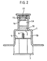
- the apparatus of FIG. 2 differs from that of FIG. 1 only in that it comprises a spray nozzle for a liquid.
- this nozzle consists of a socket 15 which can be welded or glued to the wall of the body 1, and a core is placed inside to cooperate with the outlet hole 17 of the socket 15.
- the chamber 1A is therefore originally filled with liquid, possibly also with a gas.
- the second chamber 1B can comprise a part of liquid and a part of gas. Holding the device with the outlet down, and the piston at the top, when the tip 6 will pierce the seal, the compressed air will drive the liquid from chamber 1B into chamber 1A, the liquids will mix, and the mixture, thus prepared at the time of use, will be expelled by air pressure through the nozzle. It is therefore possible to project a dose consisting of two products, the mixing of which is carried out only at the last moment, before use, and in fact, almost concomitantly.
- the tip 6 may be close to the partition 2, and the second chamber 1B initially contains no gas under pressure. Thus, with a slight movement of the pusher, the partition is pierced; you can then shake the device to mix the two liquids, and then press the button to project the mixture.
- FIG. 3 represents a variant in which the deformable wall is constituted by a substantially hemispherical wall 21, made of flexible material, similar to a pear.
- the wide end of the rod 8 comes to press on the pear.
- the crushing of the pear causes the pressure to rise, before the point 6 pierces the partition 2.
- the peripheral edge 21A of the flexible wall 21 can be glued or welded to the body of the container 1.
- This wall can be molded in one piece with the tip 6. This gives a high quality seal, and gas, air or other can be contained for a long time in the chamber 1B, without appreciable losses.
- the pusher 7 and its rod 8 can also be molded in one piece with the wall 21 and the tip 6, or can be surmounted on this wall.
- FIGS 4, 4a and 5 show an embodiment of the invention in which the spraying device is rechargeable and more particularly intended for spraying lyophilisates.
- This device is broken down into: a pusher 30 comprising a cylindrical bottom 31, itself comprising an interior face, an exterior face and an exterior peripheral edge, said pusher 30 also comprising a cylindrical side wall 32 extending upwards from said exterior peripheral edge, said cylindrical side wall 32 itself comprising a substantially cylindrical inner surface, a cylindrical outer surface and an upper end.
- a cylindrical shoulder 33 is formed on the inner face of the bottom 31, substantially centered on this inner face. On the shoulder 33 is made a grooved tip 6.
- the inner surface of the cylindrical side wall 32 comprises in the upper part a peripheral bead 9; a piston 40 of generally cylindrical shape, adapted to slide vertically inside said cylindrical side wall 32, comprising an upper face, a lower face and a substantially cylindrical peripheral surface 44.
- a cylindrical hole 41 substantially coaxial with the piston 40 passes through said piston from top to bottom and is dimensioned to allow the grooved tip 6 to pass when the piston slides downwards.
- a cylindrical housing 42 is formed in the upper face of the piston, substantially coaxial with the cylindrical hole 41, extending downward from said upper face to a flat annular surface 46.
- a peripheral groove 43 is formed in the upper part of the cylindrical peripheral surface 44. Said peripheral surface 44 is extended downwards and outwards by a peripheral sealing lip 45 pressing against the interior surface of the cylindrical side wall 32.
- the sealing lip 45 is such that the piston 40 can be inserted inside the pusher 30 by forcing the sealing lip 45 to pass over the peripheral bead 9 during assembly of the device, without damaging said sealing lip 45; a substantially helical spring 34 placed inside the pusher 30, fitted on and retained by the cylindrical shoulder 33, and adapted to push the piston 40 upwards.
- the stiffness of the spring 34 is such that it can be compressed with the force of the fingers of a user, and that it cannot force the sealing lip 45 of the piston 40 to pass over the peripheral flange 9 of the pusher 30;
- a bottle 50 of cylindrical shape comprising a cylindrical side wall, made of glass or plastic, itself composed of an upper face, a flat lower end face 52, a cylindrical outer surface and a cylindrical inner surface.
- the bottle 50 also includes a tearable partition 2 advantageously consisting of a heat-sealed film on the flat lower end face 52 of the cylindrical side wall 51. Said bottle 50 is inserted in the cylindrical housing 42.
- the interior of said bottle 50 delimits the chamber 1A, chamber 1B being delimited by the pusher 30, the piston 40 associated with the pusher 30 by the sealing lip 45, and the tearable partition 2 coming into contact with the annular horizontal face 46; -
- a tip 60 of axial symmetry coming to cover all of the components described above, comprising an orifice 3, a cylindrical interior housing 61 in which is housed the bottle 50, at least three arms 62 extending downward and provided at their lower end with a lug 63 adapted to snap into the peripheral groove 43 of the piston 40 without the force necessary for latching substantially compressing the spring 34, and such that the tensile force necessary to undo the snap-fastening is not sufficient to cause the sealing lip 45 of the piston to pass over the peripheral bead 9, said end piece 60 also comprising a
- the piston 40, the bottle 50 and the nozzle 60 are configured and dimensioned so that when the arms 62 are snapped into the peripheral groove 43, the lower end face 52 of the cylindrical side wall 51 and the heat-sealed film which is integral with the end face 52 are applied against the annular horizontal surface 46 of the piston 40 so as to provide a seal.
- the chamber 1B is sealed.
- a user When a user wishes to spray a dose of product, he takes a bottle 50 as shown in FIG. 5, that is to say comprising a stopper 4 and a tearable capsule 99 so that it can be stored. The user then removes the capsule 99 and the stopper 4, places the bottle 50 in the housing 42 of the piston 40, then caps the assembly using the end piece 60 by snapping the lugs 63 of the arms 62 into the groove peripheral 43 of the piston 40. The device is then ready to be used. The spraying is done by holding the tip 60 between the index and middle fingers, and pressing the pusher 30 with the thumb. The thrust first compresses the air included in the chamber 1B, then the grooved point 6 pierces the tearable partition 2.
- the compressed air in the chamber 1B then rushes into the chamber 1A, and sprays the lyophilisate contained in bedroom 1A.
- the lyophilisate Before spraying, the lyophilisate is in an agglomerated form; it is the violence of the projection by compressed air which puts it in powder form. Therefore, it is essential that the bottle 50 does not shrink and that the orifice 3 is at least as wide as the interior of the bottle 50, so as to avoid engorgement of the orifice by the lyophilisate, and therefore improper spraying or impossible spraying of the product.
- the spring 34 After spraying, the spring 34 returns the piston to its initial position, the nozzle 60 is removed from the assembly by a simple pull, and the empty bottle 50 is discarded. The other components of the assembly can then be reused with a new bottle 50.
- the bottle 50 and its tearable partition 2 are good thermal conductors; preferably, the bottle will therefore be made of glass, a better conductor than plastic, and the tearable partition will be made of an aluminum complex. Since the aluminum complex is a better thermal conductor than glass, it is advantageous to give the partition 2 the largest possible surface.
- the bottle 50 is provided with a stopper 4 comprising a cover from which extends a cylindrical skirt to a lower end.
- the skirt has a slot 4a over part of its height, starting from its lower end.
- the stopper 4 is partially engaged, so as to make the chamber 1A communicate with the outside through the slot 4a.
- the stopper 4 is fully engaged while the bottle is still under vacuum, which closes the chamber 1A.
- FIG. 6 and 7 The embodiment shown in Figures 6 and 7 is intended for spraying powders, that is to say products stored in powder form.
- the cylindrical side wall 51 of the bottle 50 comprises a cylindrical housing extending from the upper end face downward, to a horizontal annular surface 55, said housing defining a cylindrical interior surface 57; and - Said cylindrical housing receives a cylindrical cup 53 comprising a bottom, itself composed of a cylindrical peripheral surface of dimension smaller than the diameter of the cylindrical interior surface 57, of a substantially planar lower surface and provided with ribs 54 at a periphery outer, and a convex conical upper surface 70.
- the ribs 54 rest on the horizontal annular surface 55 so as to leave a passage between said cup 53 and the annular surface 55.
- the cup 53 also has a cylindrical side wall extending from from said bottom upward, and having a cylindrical inner surface, a cylindrical outer surface and an upper end.
- the inner surface of the cylindrical side wall and the upper surface of the bottom define a chamber 1A ′ containing the powder to spray.
- the cylindrical side wall of the cup 53 has an outside diameter less than the diameter of the cylindrical interior surface 57.
- One or more non-radial orifices 58 pass through said cylindrical side wall of the cup 53, diagonally inward of the cup and towards the bottom, opening into the interior of said cup near the base of the convex conical surface 70.
- the cylindrical side wall also includes, in the upper part of its outer surface, a peripheral sealing lip 59, dimensioned and configured to be fitted in force inside the surface 57, so that, when compressed air enters the bottle 50 after piercing the tearable partition 2, the cup 53 is not ejected to the outside.
- the bottle 50 and the cup 53 are moreover held in place by the end piece 60.
- the compressed air then passes between the ribs 54, then enters an annular space comprised between the cup 53 and the interior surface 57, and enters the chamber 1A ′ via the orifice (s) 58 whose arrangement relative to the convex conical surface 70 causes a vortex movement at the same time as the expulsion of the powder included in the chamber 1A ′.
- the chamber 1B is formed by a cylinder 81 in which slides a piston 5.
- the piston 5 fits tightly on a rod 8 of a pusher 7, in abutment against a collar 8a of the rod.
- the rod 8 is extended beyond the piston by a point 6 provided with grooves 84.
- the cylinder 81 has at one end a bottom 82 crossed by a hollow tube 83 in which the point 6 is adapted to slide.
- a spring 34 is supported on the bottom 82 and on the piston 5, so as to move the piston away from the bottom.
- An inner peripheral bead 9 is formed at a lower end of the cylinder 81, so as to prevent the piston 5 from coming out of the cylinder.
- the tube 83 has, at an upper end, a housing adapted to receive a cylindrical bottle 50 as described in the embodiment of FIG. 5, by carrying out a sealed fitting.
- an end piece 80 comprising the outlet orifice 3 fits onto the bottle 50.
- the orifice 3 is preferably of the same width as the chamber 1A, delimited by the bottle 50.
- the end piece 80 is extended radially outwards by a flange facilitating the grip.
- the piston 5 compresses the air contained in the chamber 1B until the point 6 pierces the tearable partition 2. The compressed air in the chamber 1B then escapes through grooves 84 of the tip 6 by spraying the lyophilisate contained in the chamber 1A. At the end of the race, the piston 5 abuts against one end of the tube 83 by means of ribs 85, which allow free passage between the chamber 1A and the chamber 1B. When the user releases his push, the piston 5 returns to its initial position.
Abstract
Description
La présente invention a pour objet un dispositif de projection et de pulvérisation d'une dose d'un produit divisable, en liquide ou en poudre, à des fins médicales. Il est courant d'avoir à introduire dans la gorge ou dans les narines un médicament en poudre ou en liquide. L'opération est délicate, surtout dans les narines, parce qu'il faut renverser la tête en arrière. Malgré les précautions que l'on peut prendre, une partie du médicament peut tomber en dehors de la cible. L'effet attendu ne peut être complètement obtenu, le dosage est aléatoire. La présente invention a pour but un dispositif permettant de chasser le médicament sous forme divisée. Il peut donc être envoyé dans la gorge ou les narines sans pertes, avec une efficacité maximum.The present invention relates to a device for projecting and spraying a dose of a divisible product, in liquid or powder, for medical purposes. It is common to have to introduce a powder or liquid medicine into the throat or into the nostrils. The operation is delicate, especially in the nostrils, because you have to tilt your head back. Despite the precautions that can be taken, some of the medicine may fall outside the target. The expected effect cannot be completely obtained, the dosage is random. The object of the present invention is a device for expelling the drug in divided form. It can therefore be sent into the throat or nostrils without loss, with maximum efficiency.
Conformément à la présente invention, ce résultat est obtenu par un dispositif pour projeter et pulvériser une dose d'un produit divisable, en liquide ou en poudre, notamment à usage pharmaceutique, caractérisé en ce qu'il comporte un récipient avec un orifice de sortie, une cloison déchirable séparant le récipient en deux chambres, une première chambre du côté de l'orifice de sortie prévue pour recevoir le produit divisable, et une seconde chambre comportant au moment de l'emploi un gaz comprimé, un moyen étant prévu pour perforer la cloison au moment de l'emploi.According to the present invention, this result is obtained by a device for projecting and spraying a dose of a divisible product, in liquid or powder, in particular for pharmaceutical use, characterized in that it comprises a container with an outlet orifice , a tearable partition separating the container into two chambers, a first chamber on the side of the outlet orifice intended to receive the divisible product, and a second chamber comprising at the time of use a compressed gas, a means being provided for perforating the partition at the time of use.
Le moyen pour perforer la cloison peut être une pointe de préférence rainurée, solidaire d'une paroi déformable. En appuyant sur la paroi déformable, on déplace la pointe qui vient perforer la cloison. La déformation de la paroi peut accroître ou créer la pression de gaz dans le second volume en réduisant celui-ci, le gaz étant ainsi comprimé au moment de l'emploi du dispositif. La déformation de la paroi peut être obtenue par la souplesse de la paroi, ou bien la paroi peut comporter une partie cylindrique dans laquelle coulisse un piston. Il est avantageux de faire monter la pression avant de perforer la cloison.The means for perforating the partition may be a preferably grooved point, integral with a deformable wall. By pressing on the deformable wall, the point is moved which perforates the partition. The deformation of the wall can increase or create the gas pressure in the second volume by reducing the latter, the gas being thus compressed when the device is used. The deformation of the wall can be obtained by the flexibility of the wall, or the wall can comprise a cylindrical part in which a piston slides. It is advantageous to increase the pressure before perforating the partition.
Avantageusement, le récipient peut être réalisé d'une seule pièce. Le récipient peut être en verre ou en plastique.Advantageously, the container can be made in one piece. The container can be glass or plastic.
Avantageusement, la deuxième chambre peut être remplie d'azote à une pression au moins égale à la pression atmosphérique. La première chambre peut, elle aussi, être remplie d'azote en plus du produit à disperser.Advantageously, the second chamber can be filled with nitrogen at a pressure at least equal to atmospheric pressure. The first chamber can also be filled with nitrogen in addition to the product to be dispersed.
Dans une forme particulière de réalisation de l'invention, le récipient se compose:
d'un piston comportant un trou axial le traversant, une rainure périphérique et une lèvre d'étanchéité périphérique;
d'un embout comportant l'orifice de sortie et un moyen élastique pouvant s'encliqueter dans la rainure du piston, l'embout et le piston définissant un logement pouvant recevoir un flacon comportant une paroi latérale et la cloison déchirable, ledit flacon représentant l'enceinte de ladite première chambre contenant le produit à pulvériser, et une surface de contact entre le piston et le flacon étant étanche;
et est caractérisé en ce que la paroi déformable est un cylindre creux doté d'un fond et d'une paroi latérale cylindrique à l'intérieur desquelles coulisse le piston de façon à ce que la lèvre d'étanchéité soit en contact avec ladite paroi latérale sur toute une périphérie, le moyen de perforation étant disposé sur le fond du cylindre de façon à pouvoir passer au travers du trou du piston pour percer la cloison déchirable.In a particular embodiment of the invention, the container consists of:
a piston having an axial hole passing through it, a peripheral groove and a peripheral sealing lip;
of a nozzle comprising the outlet orifice and an elastic means which can snap into the groove of the piston, the nozzle and the piston defining a housing capable of receiving a bottle having a side wall and the tearable partition, said bottle representing the 'enclosure of said first chamber containing the product to be sprayed, and a contact surface between the piston and the bottle being sealed;
and is characterized in that the deformable wall is a hollow cylinder provided with a bottom and a cylindrical side wall inside which the piston slides so that the sealing lip is in contact with said side wall over a whole periphery, the perforation means being arranged on the bottom of the cylinder so as to be able to pass through the hole of the piston to pierce the tearable partition.
Avantageusement, un ressort peut solliciter le poussoir de façon à l'éloigner du piston.Advantageously, a spring can urge the plunger so as to move it away from the piston.
Un bourrelet périphérique peut éventuellement être formé sur une surface intérieure du poussoir de façon à ce qu'au montage du dispositif, le piston puisse être inséré à l'intérieur du poussoir en forçant la lèvre d'étanchéité à passer sur le bourrelet, et en ce que la sollicitation du ressort additionnée de la force de traction nécessaire à défaire l'encliquetage du moyen élastique de l'embout ne suffise à refaire passer la lèvre d'étanchéité par dessus le bourrelet.A peripheral bead can optionally be formed on an inner surface of the pusher so that when the device is mounted, the piston can be inserted inside the pusher by forcing the sealing lip to pass over the bead, and that the biasing of the spring plus the tensile force necessary to undo the snap-fastening of the elastic means of the end piece is not enough to make the sealing lip pass over the bead again.
Dans une autre forme particulière de réalisation de l'invention une première extrémité d'un flacon délimitant la première chambre est emboîtée de façon étanche avec frottement à une extrémité de la deuxième chambre, ladite première extrémité du flacon étant fermée par la cloison déchirable, et un embout comportant l'orifice de sortie est emboîté avec frottement sur une deuxième extrémité du flacon. Dans une telle forme de réalisation, dans laquelle la paroi déformable est un piston contre lequel vient appuyer une extrémité d'une tige du poussoir, la seconde chambre étant un cylindre adapté à ce piston, un ressort peut solliciter le piston de façon à l'éloigner du flacon.In another particular embodiment of the invention, a first end of a bottle delimiting the first chamber is fitted in a sealed manner with friction at one end of the second chamber, said first end of the bottle being closed by the tearable partition, and a nozzle comprising the outlet orifice is fitted with friction on a second end of the bottle. In such an embodiment, in which the deformable wall is a piston against which abuts one end of a push rod, the second chamber being a cylinder adapted to this piston, a spring can urge the piston so as to move away from the bottle.
Le flacon des deux formes particulières de réalisation décrites ci-dessus peut être en verre ou en plastique.The bottle of the two particular embodiments described above can be made of glass or plastic.
La cloison déchirable peut être un film thermoscellé. Elle peut être réalisée dans un matériau conducteur de la chaleur. Elle peut occuper toute une section de la première chambre, de façon à présenter une transmissivité thermique maximale.The tearable partition can be a heat-sealed film. It can be made of a heat conductive material. It can occupy an entire section of the first chamber, so as to have maximum thermal transmissivity.
Dans une forme particulière de l'invention, la première chambre comporte une coupelle cylindrique contenant une poudre à pulvériser et constituée d'un fond et d'une paroi latérale périphérique s'étendant verticalement à partir du fond, ladite paroi latérale périphérique comportant en partie supérieure un moyen d'étanchéité emboîté en force à l'intérieur de la première chambre, ladite paroi latérale périphérique comportant aussi au moins un orifice non radial la traversant et dirigé en biais vers l'intérieur et vers le fond de la coupelle, ledit fond de la coupelle comportant une surface supérieure conique convexe, la coupelle coopérant avec la première chambre de façon à permettre le passage de gaz comprimé de l'intérieur de la première chambre vers l'intérieur de la coupelle par l'intermédiaire du ou des orifice(s) sans que la coupelle ne soit éjectée vers l'extérieur, et le ou les orifice(s) coopérant avec ladite surface conique pour créer un mouvement tourbillonnaire en même temps que l'expulsion de la substance à pulvériser, lors du passage du gaz comprimé.In a particular form of the invention, the first chamber comprises a cylindrical cup containing a spray powder and consisting of a bottom and a peripheral side wall extending vertically from the bottom, said peripheral side wall comprising in part upper a sealing means fitted in force inside the first chamber, said peripheral lateral wall also comprising at least one non-radial orifice passing through it and directed obliquely inwards and towards the bottom of the cup, said bottom of the cup having a convex conical upper surface, the cup cooperating with the first chamber so as to allow the passage of compressed gas from the interior of the first chamber to the interior of the cup through the orifice (s) without the cup being ejected towards the outside, and the orifice (s) cooperating with said conical surface to create a vortex movement at the same time as the expulsion of the substance to be sprayed, during the passage of the compressed gas.
Avantageusement, la première chambre contenant le produit à disperser présente une section constante, et l'orifice de sortie est de même section que ladite première chambre.Advantageously, the first chamber containing the product to be dispersed has a constant section, and the outlet orifice is of the same section as said first chamber.
Le dispositif peut être muni d'un bouchon comportant un couvercle à partir duquel s'étend une jupe jusqu'à une extrémité inférieure, ladite jupe s'emboîtant de façon étanche avec frottement dans la chambre, et est caractérisé en ce que la jupe comporte une fente sur une partie de sa hauteur, à partir de son extrémité inférieure. Une capsule métallique déchirable peut être sertie par dessus le bouchon.The device can be provided with a plug comprising a cover from which extends a skirt to a lower end, said skirt fitting in a sealed manner with friction in the chamber, and is characterized in that the skirt comprises a slit over part of its height, starting from its lower end. A tearable metal capsule can be crimped over the cap.
D'autres caractéristiques et avantages de l'invention apparaîtront au cours de la description suivante, donnée à titre d'exemple non limitatif en regard des dessins ci-joints, et qui fera bien comprendre comment l'invention peut être réalisée.Other characteristics and advantages of the invention will appear during the following description, given by way of nonlimiting example with reference to the attached drawings, and which will make it clear how the invention can be implemented.
Sur les dessins,
- - la figure 1 est une vue en coupe d'un exemple de réalisation de l'invention destiné à la projection d'une poudre,
- - la figure 2 est une vue analogue d'un exemple de réalisation destiné à la projection d'un liquide,
- - la figure 3 est une vue analogue à la figure 1 pour une variante,
- - la figure 4 est une vue en coupe d'une forme particulière de réalisation de l'invention,
- - la figure 4a est une vue en coupe du piston du dispositif représenté à la figure 4,
- - la figure 5 est une vue en coupe du flacon du dispositif représenté à la figure 4, conditionné pour être stocké,
- - la figure 6 est une vue en coupe d'une forme de réalisation de l'invention analogue à celle de la figure 4, le piston et le poussoir n'étant pas représentés,
- - la figure 7 est une vue en coupe du flacon du dispositif de la figure 6, conditionné pour être stocké, et
- - la figure 8 est une vue en coupe d'une autre forme particulière de réalisation de l'invention.
- FIG. 1 is a sectional view of an exemplary embodiment of the invention intended for spraying a powder,
- FIG. 2 is a similar view of an exemplary embodiment intended for the projection of a liquid,
- FIG. 3 is a view similar to FIG. 1 for a variant,
- FIG. 4 is a sectional view of a particular embodiment of the invention,
- FIG. 4a is a sectional view of the piston of the device shown in FIG. 4,
- FIG. 5 is a sectional view of the bottle of the device shown in FIG. 4, packaged to be stored,
- FIG. 6 is a sectional view of an embodiment of the invention similar to that of FIG. 4, the piston and the pusher not being shown,
- FIG. 7 is a sectional view of the bottle of the device of FIG. 6, conditioned to be stored, and
- - Figure 8 is a sectional view of another particular embodiment of the invention.
L'exemple de réalisation représenté sur la figure 1 est un petit appareil qui comporte un corps 1, séparé en deux chambres 1A et 1B par une cloison déchirable 2. La première chambre 1A, de petit volume, est placée du côté de l'orifice de sortie 3 qui, avant usage, est normalement fermé par un bouchon 4. Cette chambre est prévue pour recevoir une poudre qui peut occuper tout ou partie du volume de la chambre. La seconde chambre 1B est cylindrique et contient un piston 5 muni d'une pointe rainurée 6, disposée de façon à venir percer la cloison 2 lors du déplacement du piston vers la première chambre. Le piston est commandé par un poussoir 7, avec une tige d'actionnement 8. Le piston peut être maintenu à l'intérieur du cylindre par un bourrelet périphérique 9. Le corps 1 peut être moulé avec une bande déchirable 11, garantissant l'inviolabilité. La seconde chambre 1B peut être chargée initialement avec une certaine surpression de gaz de façon à accroître l'effet de projection.The embodiment shown in Figure 1 is a small device which has a
Avantageusement, la chambre 1B peut être remplie d'azote, à une pression au moins égale à la pression atmosphérique, de façon à garantir la pureté et l'asepsie du gaz contenu dans ladite chambre 1B. La chambre 1A peut, elle aussi, être remplie d'azote en plus du produit à disperser. La bande déchirable 11 peut être moulée avec le poussoir 7, ce qui permet de réaliser le corps 1 en verre aussi bien qu'en plastique.Advantageously, the
Cet appareil fonctionne de la façon suivante.This device operates as follows.
Après arrachement de la bande 11, l'utilisateur enlève le bouchon 4 et place l'appareil en position pour l'application recherchée (par exemple engagement de l'extrémité extérieure de la première chambre 1A dans une narine). Ensuite, on enfonce le poussoir 7 sur toute la course H correspondant sensiblement à la hauteur de la bande de garantie.After tearing of the
Après un déplacement h, la pointe 6 a perforé la cloison 2 qui se déchire. L'air (ou un autre gaz) comprimé par le piston 5, éventuellement en plus d'une pression initiale, est libéré et traverse rapidement la première chambre 1A vers la sortie 3 en entraînant la poudre qui est projetée à l'extérieur. Le trou fait dans la cloison 2 provoque un effet Venturi, ce qui favorise l'entraînement de la poudre par l'air. L'appareil est jeté après usage. Sa structure extrêmement simple permet cette application dans le domaine médical.After a movement h, the
On conçoit que la chambre 1A doit être plus petite que la chambre de gaz 1B pour avoir un bon balayage de la poudre. Cette première chambre 1A aura avantageusement une forme tubulaire sans rétrécissement pour favoriser l'entraînement de la poudre, pas nécessairement cylindrique. Le corps 1 présente près du poussoir 7 une collerette pour faciliter la prise de l'appareil et sa tenue pendant l'application. La pointe 6 peut présenter des rainures ou nervures longitudinales pour favoriser la déchirure de la cloison 2 et pour garantir le passage de l'air au cas où ladite cloison ne se déchire pas, mais est simplement perforée.It is understood that the
L'appareil de la figure 2 ne diffère de celui de la figure 1 qu'en ce qu'il comporte un gicleur de pulvérisation pour un liquide. Ce gicleur est dans cet exemple constitué d'une douille 15 qui peut être soudée ou collée à la paroi du corps 1, et un noyau est placé à l'intérieur pour coopérer avec le trou de sortie 17 de la douille 15. La chambre 1A est donc à l'origine remplie de liquide, avec éventuellement en plus un gaz.The apparatus of FIG. 2 differs from that of FIG. 1 only in that it comprises a spray nozzle for a liquid. In this example, this nozzle consists of a
Dans une variante d'application, il est possible d'utiliser une "bourre" 18, formant piston intermédiaire, poussée par l'air dès que la cloison 2 est percée par la pointe 6 du piston 5, la bourre poussant le liquide vers le gicleur. Ceci permet d'utiliser l'appareil dans n'importe quelle position.In an alternative application, it is possible to use a "flock" 18, forming an intermediate piston, pushed by the air as soon as the
Dans un mode d'utilisation de l'invention en rapport avec la variante de la figure 2, la seconde chambre 1B peut comprendre une partie de liquide et une partie de gaz. En tenant l'appareil avec la sortie vers le bas, et le piston en haut, lorsque la pointe 6 va percer l'opercule, l'air comprimé chassera le liquide de la chambre 1B dans la chambre 1A, les liquides se mélangeront, et le mélange, préparé ainsi au moment de l'emploi sera chassé par la pression de l'air à travers le gicleur. On peut donc ainsi projeter une dose constituée de deux produits dont le mélange n'est réalisé qu'au dernier moment, avant l'utilisation, et en fait, de façon quasi concommittante. En variante, la pointe 6 peut être proche de la cloison 2, et la seconde chambre 1B ne contient initialement pas de gaz sous pression. Ainsi, avec un faible déplacement du poussoir, on perce la cloison; on peut alors agiter l'appareil pour mélanger les deux liquides, et ensuite appuyer sur le poussoir pour projeter le mélange.In a mode of use of the invention in connection with the variant of FIG. 2, the
La figure 3 représente une variante dans laquelle la paroi déformable est constituée par une paroi sensiblement hémisphérique 21, en matériau souple, analogue à une poire. En appuyant sur le poussoir 7, l'extrémité large de la tige 8 vient appuyer sur la poire. L'écrasement de la poire provoque la montée de la pression, avant que la pointe 6 ne perfore la cloison 2.FIG. 3 represents a variant in which the deformable wall is constituted by a substantially
Le bord périphérique 21A de la paroi souple 21 peut être collé ou soudé au corps du récipient 1. Cette paroi peut être moulée en une seule pièce avec la pointe 6. On obtient ainsi une étanchéité de haute qualité, et du gaz, air ou autre peut être renfermé pendant une longue période dans la chambre 1B, sans pertes sensibles. Le poussoir 7 et sa tige 8 peuvent aussi être moulés en une seule pièce avec la paroi 21 et la pointe 6, ou peuvent être surmontés sur cette paroi.The
Les figures 4, 4a et 5 représentent une forme de réalisation de l'invention dans laquelle le dispositif de projection est rechargeable et plus particulièrement destiné à pulvériser des lyophilisats. Ce dispositif se décompose en:
-un poussoir 30 comportant un fond cylindrique 31, lui-même comportant une face intérieure, une face extérieure et un bord périphérique extérieur, ledit poussoir 30 comportant aussi une paroi latérale cylindrique 32 s'étendant vers le haut à partir dudit bord périphérique extérieur, ladite paroi latérale cylindrique 32 comportant elle-même une surface intérieure sensiblement cylindrique, une surface extérieure cylindrique et une extrémité supérieure. Un épaulement cylindrique 33 est réalisé sur la face intérieure du fond 31, sensiblement centré sur cette face intérieure. Sur l'épaulement 33 est réalisé une pointe rainurée 6. La surface intérieure de la paroi latérale cylindrique 32 comporte en partie supérieure un bourrelet périphérique 9;
-un piston 40 de forme généralement cylindrique, adapté à coulisser verticalement à l'intérieur de ladite paroi latérale cylindrique 32, comportant une face supérieure, une face inférieure et une surface périphérique sensiblement cylindrique 44. Un trou cylindrique 41 sensiblement coaxial au piston 40 traverse ledit piston de haut en bas et est dimensionné pour laisser passer la pointe rainurée 6 lorsque le piston coulisse vers le bas. Un logement cylindrique 42 est réalisé dans la face supérieure du piston, sensiblement coaxial au trou cylindrique 41, s'étendant vers le bas à partir de ladite face supérieure jusqu'à une surface annulaire plane 46. Une rainure périphérique 43 est réalisée en partie supérieure de la surface périphérique cylindrique 44. Ladite surface périphérique 44 est prolongée vers le bas et vers l'extérieur par une lèvre d'étanchéité périphérique 45 s'appuyant contre la surface intérieure de la paroi latérale cylindrique 32. La lèvre d'étanchéité 45 est telle que le piston 40 puisse être inséré à l'intérieur du poussoir 30 en forçant la lèvre d'étanchéité 45 à passer au-dessus du bourrelet périphérique 9 lors du montage du dispositif, sans endommager ladite lèvre d'étanchéité 45;
-un ressort sensiblement hélicoïdal 34 placé à l'intérieur du poussoir 30, emboîté sur et retenu par l'épaulement cylindrique 33, et adapté à repousser le piston 40 vers le haut. La raideur du ressort 34 est telle qu'il puisse être comprimé à la force des doigts d'un utilisateur, et qu'il ne puisse pas forcer la lèvre d'étanchéité 45 du piston 40 à repasser par dessus le bourrelet périphérique 9 du poussoir 30;
-un flacon 50 de forme cylindrique comportant une paroi latérale cylindrique, en verre ou en plastique, elle-même composée d'une face supérieure, d'une face d'extrémité inférieure plane 52, d'une surface extérieure cylindrique et d'une surface intérieure cylindrique. Le flacon 50 comporte aussi une cloison déchirable 2 consistant avantageusement en un film thermoscellé sur la face d'extrémité inférieure plane 52 de la paroi latérale cylindrique 51. Ledit flacon 50 est inséré dans le logement cylindrique 42. L'intérieur dudit flacon 50 délimite la chambre 1A, la chambre 1B étant délimitée par le poussoir 30, le piston 40 associé au poussoir 30 par la lèvre d'étanchéité 45, et la cloison déchirable 2 venant en contact avec la face horizontale annulaire 46;
- un embout 60 de symétrie axiale, venant coiffer l'ensemble des composants décrits ci-dessus, comportant un orifice 3, un logement intérieur cylindrique 61 dans lequel vient se loger le flacon 50, au moins trois bras 62 s'étendant vers le bas et dotés à leur extrémité inférieure d'un ergot 63 adapté à s'encliqueter dans la rainure périphérique 43 du piston 40 sans que la force nécessaire à l'encliquetage ne comprime sensiblement le ressort 34, et tel que la force de traction nécessaire pour défaire l'encliquetage ne soit pas suffisante pour faire repasser la lèvre d'étanchéité 45 du piston par dessus le bourrelet périphérique 9, ledit embout 60 comprenant aussi un manchon périphérique cylindrique 64 s étendant vers le bas, prolongé par une colerette 65 s'étendant radialement vers l'extérieur, destinée à favoriser la prise par un utilisateur.Figures 4, 4a and 5 show an embodiment of the invention in which the spraying device is rechargeable and more particularly intended for spraying lyophilisates. This device is broken down into:
a
a
a substantially
a
- A
Le piston 40, le flacon 50 et l'embout 60 sont configurés et dimensionnés de façon à ce que lorsque les bras 62 sont encliquetés dans la rainure périphérique 43, la face d'extrémité inférieure 52 de la paroi latérale cylindrique 51 et le film thermoscellé qui est solidaire de la face d'extrémité 52 soient appliqués contre la surface horizontale annulaire 46 du piston 40 de façon à réaliser une étanchéité. Ainsi, la chambre 1B est étanche.The
Lorsqu'un utilisateur désire pulvériser une dose de produit, il prend un flacon 50 tel que représenté sur la figure 5, c'est-à-dire comportant un bouchon 4 et une capsule 99 déchirable pour pouvoir être stocké. L'utilisateur enlève alors la capsule 99 et le bouchon 4, place le flacon 50 dans le logement 42 du piston 40, puis coiffe l'ensemble à l'aide de l'embout 60 en encliquetant les ergots 63 des bras 62 dans la rainure périphérique 43 du piston 40. Le dispositif est alors prêt à être utilisé. La pulvérisation se fait en tenant l'embout 60 entre l'index et le majeur, et en appuyant sur le poussoir 30 à l'aide du pouce. La poussée comprime d'abord l'air compris dans la chambre 1B, puis la pointe rainurée 6 vient percer la cloison déchirable 2. L'air comprimé dans la chambre 1B s'engouffre alors dans la chambre 1A, et pulvérise le lyophilisat contenu dans la chambre 1A. Avant pulvérisation, le lyophilisat est sous une forme agglomérée ; c'est la violence de la projection par l'air comprimé qui le met sous forme pulvérulente. De ce fait, il est indispensable que le flacon 50 ne présente pas de rétrécissement et que l'orifice 3 soit au moins aussi large que l'intérieur du flacon 50, de façon à éviter un engorgement de l'orifice par le lyophilisat, et donc une mauvaise pulvérisation ou une pulvérisation impossible du produit.When a user wishes to spray a dose of product, he takes a
Après pulvérisation, le ressort 34 remet le piston dans sa position initiale, l'embout 60 est démonté de l'assemblage par une simple traction, et le flacon 50 vide est jeté. Les autres composants de l'assemblage peuvent alors être réutilisés avec un nouveau flacon 50.After spraying, the
Lors de la fabrication du lyophilisat, une solution du produit à lyophiliser est placée dans le flacon 50 puis congelée à très basse température, puis réchauffée brutalement sous un vide très poussé, ce qui provoque la sublimation instantannée du solvant, généralement de l'eau. Durant ce processus, il est donc important que le flacon 50 et sa cloison déchirable 2 soient de bons conducteurs thermiques; de préférence, le flacon sera donc réalisé en verre, meilleur conducteur que le plastique, et la cloison déchirable sera réalisée en un complexe d'aluminium. Le complexe d'aluminium étant meilleur conducteur thermique que le verre, il est avantageux de donner à la cloison 2 une surface la plus grande possible.During the manufacture of the lyophilisate, a solution of the product to be lyophilized is placed in the
Le fait de réaliser le flacon en verre et la cloison déchirable en complexe d'aluminium, favorise aussi la conservation du lyophilisat dans de bonnes conditions de sécheresse.The fact of making the glass bottle and the tearable partition in aluminum complex, also promotes the preservation of the lyophilisate in good conditions of dryness.
Le flacon 50 est doté d'un bouchon 4 comportant un couvercle à partir duquel s'étend une jupe cylindrique jusqu'à une extrémité inférieure. La jupe comporte une fente 4a sur une partie de sa hauteur, à partir de son extrémité inférieure. Pendant le processus de lyophilisation, le bouchon 4 est partiellement engagé, de façon à faire communiquer la chambre 1A avec l'extérieur par la fente 4a. A la fin de la lyophilisation, le bouchon 4 est engagé à fond pendant que le flacon est encore sous vide, ce qui ferme la chambre 1A.The
La forme de réalisation représentée sur les figures 6 et 7 est destinée à la pulvérisation de poudres, c'est-à-dire de produits stockés sous forme pulvérulente.The embodiment shown in Figures 6 and 7 is intended for spraying powders, that is to say products stored in powder form.
Elle diffère de la précédente forme de réalisation par le fait que :
- la paroi latérale cylindrique 51 du flacon 50 comporte un logement cylindrique s'étendant à partir de la face d'extrémité supérieure vers le bas, jusqu'à une surface annulaire horizontale 55, ledit logement délimitant une surface intérieure cylindrique 57 ; et
- ledit logement cylindrique reçoit une coupelle cylindrique 53 comportant un fond, lui-même composé d'une surface périphérique cylindrique de dimension inférieure au diamètre de la surface intérieure cylindrique 57, d'une surface inférieure sensiblement plane et munie de nervures 54 en une périphérie extérieure, et une surface supérieure conique convexe 70. Les nervures 54 reposent sur la surface annulaire horizontale 55 de façon à laisser un passage entre ladite coupelle 53 et la surface annulaire 55. La coupelle 53 comporte aussi une paroi latérale cylindrique s'étendant à partir dudit fond vers le haut, et comportant une surface intérieure cylindrique, une surface extérieure cylindrique et une extrémité supérieure. La surface intérieure de la paroi latérale cylindrique et la surface supérieure du fond délimitent une chambre 1A′ contenant la poudre à pulvériser. La paroi latérale cylindrique de la coupelle 53 a un diamètre extérieur inférieur au diamètre de la surface intérieure cylindrique 57. Un ou plusieurs orifices non radiaux 58 traversent ladite paroi latérale cylindrique de la coupelle 53, en biais vers l'intérieur de la coupelle et vers le bas, débouchant à l'intérieur de ladite coupelle près de la base de la surface conique convexe 70. La paroi latérale cylindrique comporte aussi en partie supérieure de sa surface extérieure une lèvre d'étanchéité périphérique 59, dimensionnée et configurée pour être emboîtée en force à l'intérieur de la surface 57, de façon à ce que, lorsque de l'air comprimé pénètre dans le flacon 50 après percement de la cloison déchirable 2, la coupelle 53 ne soit pas éjectée vers l'extérieur. De préférence, le flacon 50 et la coupelle 53 sont de plus maintenus en place par l'embout 60.It differs from the previous embodiment in that:
- The
- Said cylindrical housing receives a
Dans ces conditions, l'air comprimé passe alors entre les nervures 54, puis entre dans un espace annulaire compris entre la coupelle 53 et la surface intérieure 57, et pénètre dans la chambre 1A′ par l'intermédiaire du ou des orifices 58 dont la disposition par rapport à la surface conique convexe 70 entraîne un mouvement tourbillonnaire en même temps que l'expulsion de la poudre comprise dans la chambre 1A′.Under these conditions, the compressed air then passes between the
Une autre forme de réalisation est présentée à la figure 8. Dans cette forme de réalisation, la chambre 1B est formée par un cylindre 81 dans lequel coulisse un piston 5. Le piston 5 s'emboîte de façon étanche sur une tige 8 d'un poussoir 7, en butée contre un collet 8a de la tige. La tige 8 se prolonge au-delà du piston par une pointe 6 dotée de rainures 84. Le cylindre 81 comporte en une extrémité un fond 82 traversé par un tube 83 creux dans lequel la pointe 6 est adaptée à coulisser. Un ressort 34 s'appuie sur le fond 82 et sur le piston 5, de façon à éloigner le piston du fond. Un bourrelet périphérique intérieur 9 est formé en une extrémité inférieure du cylindre 81, de façon à empêcher le piston 5 de sortir du cylindre. Le tube 83 comporte en une extrémité supérieure un logement adapté à recevoir un flacon cylindrique 50 tel que décrit dans la forme de réalisation de la figure 5, en réalisant un emboîtement étanche. De plus, un embout 80 comportant l'orifice de sortie 3 vient s'emboîter sur le flacon 50. L'orifice 3 est de préférence de même largeur que la chambre 1A, délimitée par le flacon 50. L'embout 80 est prolongé radialement vers l'extérieur par une colerette facilitant la prise.Another embodiment is shown in Figure 8. In this embodiment, the
Lorsqu'un utilisateur appuie sur le poussoir 7, le piston 5 comprime l'air contenu dans la chambre 1B jusqu'à ce que la pointe 6 perce la cloison déchirable 2. L'air comprimé dans la chambre 1B s'échappe alors au travers des rainures 84 de la pointe 6 en pulvérisant le lyophilisat contenu dans la chambre 1A. En fin de course, le piston 5 vient en butée contre une extrémité du tube 83 par l'intermédiaire de nervures 85, qui laissent un passage libre entre la chambre 1A et la chambre 1B. Lorsque l'utilisateur relâche sa poussée, le piston 5 revient dans sa position initiale.When a user presses the plunger 7, the
Claims (28)
- d'un piston (40) comportant un trou axial (41) le traversant, une rainure périphérique (43) et une lèvre d'étanchéité périphérique (45);
- d'un embout (60) comportant l'orifice de sortie (3) et un moyen élastique (62, 63) pouvant s'encliqueter dans la rainure (43) du piston, l'embout et le piston définissant un logement pouvant recevoir un cartouche (50) comportant une paroi latérale (51) et la cloison déchirable (2), ledit flacon représentant l'enceinte de ladite première chambre (1A) contenant le produit à pulvériser, et une surface de contact entre le piston (40) et le cartouche (50) étant étanche;
et caractérisé en ce que la paroi déformable est un cylindre creux (30) doté d'un fond (31) et d'une paroi latérale cylindrique (32) à l'intérieur desquelles coulisse le piston (40) de façon à ce que la lèvre d'étanchéité (45) soit en contact avec ladite paroi latérale (32) sur toute une périphérie, la pointe rainurée (6) étant disposé sur le fond (31) du cylindre de façon à pouvoir passer au travers du trou (41) pour percer la cloison déchirable (2).10.- Device according to claim 1, characterized in that the container (1) consists of:
- a piston (40) comprising an axial hole (41) passing through it, a peripheral groove (43) and a peripheral sealing lip (45);
- a nozzle (60) comprising the outlet orifice (3) and an elastic means (62, 63) which can snap into the groove (43) of the piston, the nozzle and the piston defining a housing which can receive a cartridge (50) comprising a side wall (51) and the tearable partition (2), said bottle representing the enclosure of said first chamber (1A) containing the product to be sprayed, and a contact surface between the piston (40) and the cartridge (50) being sealed;
and characterized in that the deformable wall is a hollow cylinder (30) provided with a bottom (31) and a cylindrical side wall (32) inside which the piston (40) slides so that the sealing lip (45) is in contact with said side wall (32) over an entire periphery, the grooved point (6) being disposed on the bottom (31) of the cylinder so as to be able to pass through the hole (41) to pierce the tearable partition (2).
Applications Claiming Priority (2)
| Application Number | Priority Date | Filing Date | Title |
|---|---|---|---|
| FR8908971A FR2649323B1 (en) | 1989-07-04 | 1989-07-04 | DEVICE FOR SPRAYING AND SPRAYING A DOSE OF A DIVIDABLE PRODUCT |
| FR8908971 | 1989-07-04 |
Publications (2)
| Publication Number | Publication Date |
|---|---|
| EP0407276A2 true EP0407276A2 (en) | 1991-01-09 |
| EP0407276A3 EP0407276A3 (en) | 1991-11-27 |
Family
ID=9383450
Family Applications (1)
| Application Number | Title | Priority Date | Filing Date |
|---|---|---|---|
| EP19900401881 Withdrawn EP0407276A3 (en) | 1989-07-04 | 1990-06-29 | Dispensing and pulverizing apparatus for a dose of a divisible product |
Country Status (4)
| Country | Link |
|---|---|
| EP (1) | EP0407276A3 (en) |
| JP (1) | JPH03131271A (en) |
| CA (1) | CA2020425A1 (en) |
| FR (1) | FR2649323B1 (en) |
Cited By (31)
| Publication number | Priority date | Publication date | Assignee | Title |
|---|---|---|---|---|
| WO1993011818A1 (en) * | 1991-12-10 | 1993-06-24 | Novo Nordisk A/S | Disposable dispenser for drugs |
| US5307953A (en) * | 1991-12-03 | 1994-05-03 | Glaxo Group Limited | Single dose dispenser having a piercing member |
| DE4412041A1 (en) * | 1994-04-08 | 1995-10-12 | Pfeiffer Erich Gmbh & Co Kg | Discharge device for flowable media, in particular for discharge in just one stroke |
| DE19637101A1 (en) * | 1996-09-12 | 1998-03-19 | Pfeiffer Erich Gmbh & Co Kg | Discharge device for media |
| US5819730A (en) * | 1993-06-09 | 1998-10-13 | Glaxo Wellcome Australia Ltd. | Device for administering pharmaceutical substances |
| WO1999046055A1 (en) * | 1998-03-10 | 1999-09-16 | Valois S.A. | Reservoir, reservoir filling method and device for dispensing fluid contained in the reservoir |
| FR2780388A1 (en) | 1998-06-24 | 1999-12-31 | Valois Sa | Container for single dose of fluid or powdered product e.g. medication |
| US6119688A (en) * | 1991-08-26 | 2000-09-19 | 3M Innovative Properties Company | Powder dispenser |
| US6189739B1 (en) | 1996-06-01 | 2001-02-20 | Astrazeneca Ab | Pump dispenser with threshold actuation and restoring spring |
| GB2367756A (en) * | 2000-10-12 | 2002-04-17 | Bespak Plc | Disposable dispensing apparatus including a frangible membrane |
| EP1329237A1 (en) * | 2002-01-22 | 2003-07-23 | Bespak Plc | Dispensing device |
| WO2003080163A1 (en) * | 2002-03-20 | 2003-10-02 | Advanced Inhalation Research, Inc. | Puncturing means for use in an inhalation device |
| WO2004004922A1 (en) * | 2002-07-09 | 2004-01-15 | Optinose As | Delivery devices |
| EP1402913A1 (en) * | 2001-06-15 | 2004-03-31 | Otsuka Pharmaceutical Co., Ltd. | Dry powder inhalation system for transpulmonary administration |
| US6732732B2 (en) | 2001-04-16 | 2004-05-11 | Advanced Inhalation Research, Inc. | Inhalation device and method |
| GB2412326A (en) * | 2004-03-26 | 2005-09-28 | Bespak Plc | Hand-held dispenser |
| US7086571B2 (en) | 2001-04-30 | 2006-08-08 | Bespak Plc | Valves for pressurized dispensing containers |
| US7455248B2 (en) | 2004-03-17 | 2008-11-25 | Genzyme Corporation | Powder delivery device |
| US7491194B1 (en) | 2004-02-03 | 2009-02-17 | David Oliwa | Remote control valve for urine collection bag |
| CN101366989B (en) * | 2001-06-15 | 2012-03-21 | 大塚制药株式会社 | Dry powder inhalation system for transpulmonary dosage |
| US8496002B2 (en) | 2007-06-12 | 2013-07-30 | Civitas Therapeutics, Inc. | Powder inhaler devices |
| US8550074B2 (en) | 2009-01-15 | 2013-10-08 | Manta Devices, Llc | Delivery device and related methods |
| US8607787B2 (en) | 2007-07-06 | 2013-12-17 | Manta Devices, Llc | Dose delivery device for inhalation |
| US8763605B2 (en) | 2005-07-20 | 2014-07-01 | Manta Devices, Llc | Inhalation device |
| US9283336B2 (en) | 2010-03-19 | 2016-03-15 | Manta Devices, Llc | Delivery device and related methods |
| US9649454B2 (en) | 2012-05-03 | 2017-05-16 | Manta Devices, Llc | Delivery device and related methods |
| US11103659B2 (en) | 2011-07-06 | 2021-08-31 | Manta Devices, Llc | Delivery device and related methods |
| US11147936B2 (en) | 2014-05-02 | 2021-10-19 | Manta Devices, Llc | Dose delivery device with cover connected to dose chamber seal |
| US11224704B2 (en) | 2007-07-06 | 2022-01-18 | Manta Devices, Llc | Dose delivery device for inhalation |
| EP3884980A4 (en) * | 2018-11-19 | 2022-08-17 | Shin Nippon Biomedical Laboratories, Ltd. | Medicine dispensing device and method for manufacturing same |
| FR3121047A1 (en) | 2021-03-29 | 2022-09-30 | Aptar France Sas | Nasal powder delivery device |
Families Citing this family (3)
| Publication number | Priority date | Publication date | Assignee | Title |
|---|---|---|---|---|
| US5337740A (en) * | 1991-08-01 | 1994-08-16 | New England Pharmaceuticals, Inc. | Inhalation devices |
| US5411175A (en) * | 1993-03-08 | 1995-05-02 | New England Pharmaceuticals, Inc. | Cartridges, devices and methods for dispensing liquids |
| US20150041496A1 (en) * | 2013-08-08 | 2015-02-12 | Sungmoon Kim | Single use enhancement for dispenser assembly |
Citations (9)
| Publication number | Priority date | Publication date | Assignee | Title |
|---|---|---|---|---|
| GB250920A (en) * | 1925-04-17 | 1926-07-29 | Renee Marie Louise Lemoine | Pocket atomiser |
| BE388352A (en) * | 1931-05-06 | 1932-06-30 | Vincent Jean | Advanced sprayer. |
| US2533065A (en) * | 1947-03-08 | 1950-12-05 | George V Taplin | Micropulverized therapeutic agents |
| CH518744A (en) * | 1970-01-30 | 1972-02-15 | Ciba Geigy Ag | Device for the application of powdery substances |
| FR2256084A1 (en) * | 1973-12-26 | 1975-07-25 | Ciba Geigy Ag | |
| US3949751A (en) * | 1970-03-03 | 1976-04-13 | Fisons Limited | Method and device for dispensing medicament to the body |
| FR2294937A1 (en) * | 1974-12-18 | 1976-07-16 | Neve Rene | Two-compartment bottle for two-component pharmaceutical prods. - which must be kept apart until the moment of injection |
| US4093124A (en) * | 1976-07-26 | 1978-06-06 | L'oreal | Atomizer with air inlet valve |
| EP0293290A1 (en) * | 1987-05-25 | 1988-11-30 | Societe De Conseils Et D'etudes Des Emballages S C E E | Closure device for containers |
-
1989
- 1989-07-04 FR FR8908971A patent/FR2649323B1/en not_active Expired - Fee Related
-
1990
- 1990-06-29 EP EP19900401881 patent/EP0407276A3/en not_active Withdrawn
- 1990-07-04 JP JP17720790A patent/JPH03131271A/en active Pending
- 1990-07-04 CA CA 2020425 patent/CA2020425A1/en not_active Abandoned
Patent Citations (9)
| Publication number | Priority date | Publication date | Assignee | Title |
|---|---|---|---|---|
| GB250920A (en) * | 1925-04-17 | 1926-07-29 | Renee Marie Louise Lemoine | Pocket atomiser |
| BE388352A (en) * | 1931-05-06 | 1932-06-30 | Vincent Jean | Advanced sprayer. |
| US2533065A (en) * | 1947-03-08 | 1950-12-05 | George V Taplin | Micropulverized therapeutic agents |
| CH518744A (en) * | 1970-01-30 | 1972-02-15 | Ciba Geigy Ag | Device for the application of powdery substances |
| US3949751A (en) * | 1970-03-03 | 1976-04-13 | Fisons Limited | Method and device for dispensing medicament to the body |
| FR2256084A1 (en) * | 1973-12-26 | 1975-07-25 | Ciba Geigy Ag | |
| FR2294937A1 (en) * | 1974-12-18 | 1976-07-16 | Neve Rene | Two-compartment bottle for two-component pharmaceutical prods. - which must be kept apart until the moment of injection |
| US4093124A (en) * | 1976-07-26 | 1978-06-06 | L'oreal | Atomizer with air inlet valve |
| EP0293290A1 (en) * | 1987-05-25 | 1988-11-30 | Societe De Conseils Et D'etudes Des Emballages S C E E | Closure device for containers |
Cited By (63)
| Publication number | Priority date | Publication date | Assignee | Title |
|---|---|---|---|---|
| US6119688A (en) * | 1991-08-26 | 2000-09-19 | 3M Innovative Properties Company | Powder dispenser |
| US5307953A (en) * | 1991-12-03 | 1994-05-03 | Glaxo Group Limited | Single dose dispenser having a piercing member |
| AU661095B2 (en) * | 1991-12-10 | 1995-07-13 | Novo Nordisk A/S | Dispenser |
| WO1993011818A1 (en) * | 1991-12-10 | 1993-06-24 | Novo Nordisk A/S | Disposable dispenser for drugs |
| US5819730A (en) * | 1993-06-09 | 1998-10-13 | Glaxo Wellcome Australia Ltd. | Device for administering pharmaceutical substances |
| DE4412041A1 (en) * | 1994-04-08 | 1995-10-12 | Pfeiffer Erich Gmbh & Co Kg | Discharge device for flowable media, in particular for discharge in just one stroke |
| US6189739B1 (en) | 1996-06-01 | 2001-02-20 | Astrazeneca Ab | Pump dispenser with threshold actuation and restoring spring |
| EP0829307A3 (en) * | 1996-09-12 | 1998-09-02 | Ing. Erich Pfeiffer GmbH | Dispenser for fluids |
| US5967369A (en) * | 1996-09-12 | 1999-10-19 | Ing. Erich Pfeiffer Gmbh | Dispenser for media having measured reservoir |
| DE19637101A1 (en) * | 1996-09-12 | 1998-03-19 | Pfeiffer Erich Gmbh & Co Kg | Discharge device for media |
| WO1999046055A1 (en) * | 1998-03-10 | 1999-09-16 | Valois S.A. | Reservoir, reservoir filling method and device for dispensing fluid contained in the reservoir |
| US6398074B1 (en) | 1998-03-10 | 2002-06-04 | Valois S.A. | Reservoir, reservoir filling method and device for dispensing fluid contained in the reservoir |
| CN1106888C (en) * | 1998-03-10 | 2003-04-30 | 瓦卢瓦股份有限公司 | Reservoir, reservoir filling method and device for dispensing fluid contained in reservoir |
| FR2780388A1 (en) | 1998-06-24 | 1999-12-31 | Valois Sa | Container for single dose of fluid or powdered product e.g. medication |
| GB2367756A (en) * | 2000-10-12 | 2002-04-17 | Bespak Plc | Disposable dispensing apparatus including a frangible membrane |
| GB2367756B (en) * | 2000-10-12 | 2003-01-08 | Bespak Plc | Dispensing apparatus |
| US6866039B1 (en) | 2000-10-12 | 2005-03-15 | Bespak Plc | Dispensing apparatus |
| US6732732B2 (en) | 2001-04-16 | 2004-05-11 | Advanced Inhalation Research, Inc. | Inhalation device and method |
| US7278425B2 (en) | 2001-04-16 | 2007-10-09 | Alkermes, Inc. | Inhalation device and method |
| US7086571B2 (en) | 2001-04-30 | 2006-08-08 | Bespak Plc | Valves for pressurized dispensing containers |
| HRP20040033B1 (en) * | 2001-06-15 | 2007-11-30 | Otsuka Pharmaceutical Co. | Dry powder inhalation system for transpulmonary administration |
| AU2008200583B2 (en) * | 2001-06-15 | 2011-05-19 | Otsuka Pharmaceutical Co., Ltd. | Dry powder inhalation system for transpulmonary administration |
| EP1402913A4 (en) * | 2001-06-15 | 2004-12-01 | Otsuka Pharma Co Ltd | Dry powder inhalation system for transpulmonary administration |
| EP1402913A1 (en) * | 2001-06-15 | 2004-03-31 | Otsuka Pharmaceutical Co., Ltd. | Dry powder inhalation system for transpulmonary administration |
| US8443799B2 (en) | 2001-06-15 | 2013-05-21 | Otsuka Pharmaceutical Co., Ltd. | Dry powder inhalation system for transpulmonary administration |
| US8333193B2 (en) | 2001-06-15 | 2012-12-18 | Otsuka Pharmaceutical Co., Ltd. | Dry powder inhalation system for transpulmonary administration |
| EP1579855A1 (en) * | 2001-06-15 | 2005-09-28 | Otsuka Pharmaceutical Co., Ltd. | Novel dry powder inhalation system for transpulmonary administration |
| CN101366989B (en) * | 2001-06-15 | 2012-03-21 | 大塚制药株式会社 | Dry powder inhalation system for transpulmonary dosage |
| EP1688133A1 (en) * | 2001-06-15 | 2006-08-09 | Otsuka Pharmaceutical Co., Ltd. | Freeze-dried composition for transpulmonary administration |
| WO2004054555A1 (en) | 2001-06-15 | 2004-07-01 | Otsuka Pharmaceutical Co., Ltd. | Novel dry powder inhalation system for transpulmonary administration |
| US7735485B2 (en) | 2001-06-15 | 2010-06-15 | Otsuka Pharmaceutical Co., Ltd. | Dry powder inhalation system for transpulmonary administration |
| AU2002311213B2 (en) * | 2001-06-15 | 2007-12-13 | Otsuka Pharmaceutical Co., Ltd. | Dry powder inhalation system for transpulmonary administration |
| AP1861A (en) * | 2001-06-15 | 2008-07-02 | Otsuka Pharma Co Ltd | Dry powder inhalation system for transpulmonary administration |
| CN100427077C (en) * | 2001-06-15 | 2008-10-22 | 大塚制药株式会社 | Dry powder inhalation system for transpulmonary administration |
| US7448379B2 (en) | 2001-06-15 | 2008-11-11 | Otsuka Pharmaceutical Co., Ltd. | Composition, vessel, dry powder inhalation system, and related methods for transpulmonary administration |
| EP1688134A3 (en) * | 2001-06-15 | 2009-11-18 | Otsuka Pharmaceutical Co., Ltd. | Dry powder inhaler for transpulmonary administration |
| EP1579855A4 (en) * | 2001-06-15 | 2009-11-04 | Otsuka Pharma Co Ltd | Novel dry powder inhalation system for transpulmonary administration |
| US6945953B2 (en) | 2002-01-22 | 2005-09-20 | Bespak Plc | Dispensing apparatus for delivering powdered product |
| EP1329237A1 (en) * | 2002-01-22 | 2003-07-23 | Bespak Plc | Dispensing device |
| WO2003080163A1 (en) * | 2002-03-20 | 2003-10-02 | Advanced Inhalation Research, Inc. | Puncturing means for use in an inhalation device |
| WO2004004922A1 (en) * | 2002-07-09 | 2004-01-15 | Optinose As | Delivery devices |
| US7934503B2 (en) | 2002-07-09 | 2011-05-03 | Optinose As | Delivery devices |
| US7491194B1 (en) | 2004-02-03 | 2009-02-17 | David Oliwa | Remote control valve for urine collection bag |
| US7455248B2 (en) | 2004-03-17 | 2008-11-25 | Genzyme Corporation | Powder delivery device |
| GB2412326A (en) * | 2004-03-26 | 2005-09-28 | Bespak Plc | Hand-held dispenser |
| US11672927B2 (en) | 2005-07-20 | 2023-06-13 | Manta Devices, Llc | Inhalation device |
| US8763605B2 (en) | 2005-07-20 | 2014-07-01 | Manta Devices, Llc | Inhalation device |
| US10632268B2 (en) | 2005-07-20 | 2020-04-28 | Manta Devices, Llc | Inhalation device |
| US11491287B2 (en) | 2005-07-20 | 2022-11-08 | Manta Devices, Llc | Inhalation device |
| US8496002B2 (en) | 2007-06-12 | 2013-07-30 | Civitas Therapeutics, Inc. | Powder inhaler devices |
| US8607787B2 (en) | 2007-07-06 | 2013-12-17 | Manta Devices, Llc | Dose delivery device for inhalation |
| US11224704B2 (en) | 2007-07-06 | 2022-01-18 | Manta Devices, Llc | Dose delivery device for inhalation |
| US9713684B2 (en) | 2007-07-06 | 2017-07-25 | Manta Devices, Llc | Dose delivery device for inhalation with plunger |
| US9919115B2 (en) | 2007-07-06 | 2018-03-20 | Manta Devices, Llc | Dose delivery device for inhalation with first and second portions to open a dose chamber |
| US9004064B2 (en) | 2009-01-15 | 2015-04-14 | Manta Devices, Llc | Delivery device and related methods |
| US8550074B2 (en) | 2009-01-15 | 2013-10-08 | Manta Devices, Llc | Delivery device and related methods |
| US9283336B2 (en) | 2010-03-19 | 2016-03-15 | Manta Devices, Llc | Delivery device and related methods |
| US11103659B2 (en) | 2011-07-06 | 2021-08-31 | Manta Devices, Llc | Delivery device and related methods |
| US9649454B2 (en) | 2012-05-03 | 2017-05-16 | Manta Devices, Llc | Delivery device and related methods |
| US11147936B2 (en) | 2014-05-02 | 2021-10-19 | Manta Devices, Llc | Dose delivery device with cover connected to dose chamber seal |
| EP3884980A4 (en) * | 2018-11-19 | 2022-08-17 | Shin Nippon Biomedical Laboratories, Ltd. | Medicine dispensing device and method for manufacturing same |
| FR3121047A1 (en) | 2021-03-29 | 2022-09-30 | Aptar France Sas | Nasal powder delivery device |
| WO2022208014A1 (en) | 2021-03-29 | 2022-10-06 | Aptar France Sas | Device for nasal delivery of powder |
Also Published As
| Publication number | Publication date |
|---|---|
| JPH03131271A (en) | 1991-06-04 |
| EP0407276A3 (en) | 1991-11-27 |
| FR2649323B1 (en) | 1995-06-30 |
| FR2649323A1 (en) | 1991-01-11 |
| CA2020425A1 (en) | 1991-01-05 |
Similar Documents
| Publication | Publication Date | Title |
|---|---|---|
| EP0407276A2 (en) | Dispensing and pulverizing apparatus for a dose of a divisible product | |
| EP0694483B1 (en) | Container for the storage of at least two products, and for the mixture and distribution of these products | |
| CA1275077A (en) | Container for conditioning and distributing a liquid and at least one additional product segregated while in storage | |
| BE1005867A5 (en) | DEVICE. | |
| EP0792135B1 (en) | Syringe device attachable to a bottle | |
| EP0260179A1 (en) | Assembly for the separate storage of two products and simultaneous distribution after mixing | |
| FR2717086A1 (en) | Syringe system for mixing two compounds | |
| EP0591365A1 (en) | Device for dispensing a predetermined dose of fluid product, and method of filling thereof. | |
| CA2299595C (en) | Packaging for mixing a product with several components | |
| FR2806271A1 (en) | DEVICE FOR THE EXTEMPORANEOUS MIXING OF AT LEAST TWO PRODUCTS | |
| FR2524348A1 (en) | Vaporising pump made with plastics parts - has spray orifice which closes automatically after vapourisation under plastics spring action | |
| WO2004054721A1 (en) | Manually-actuated metering pump | |
| FR2558801A1 (en) | ASSEMBLY FOR DISPENSING DOSES OF A SUBSTANCE OF LIQUID OR PASTY CONSISTENCY | |
| FR2658487A1 (en) | Device for spraying a medicine constituted by a mixture to be formed at the moment of emission | |
| CH658637A5 (en) | DROPPER ASSEMBLY. | |
| EP0905049B1 (en) | Container for a three-component product | |
| EP1124646B1 (en) | Reservoir provided with a device for closing and/or filling and sprayer for dispensing a fluid product comprising same | |
| EP0562943B1 (en) | Double chambered package | |
| EP0499520B1 (en) | Spraying or dispensing device for a fluid product comprising a sliding element within its inlet port | |
| FR2667050A1 (en) | Device for spraying in atomised or pulsed form a defined dose of liquid or viscous product, and particularly of a medicine, and method of keeping this device fluid-tight | |
| CH545730A (en) | Two part prepn storage container - esp for pharmaceuticals with components separately stored until required for use | |
| WO2009056770A1 (en) | Metering device adaptable to a container | |
| WO2016120144A1 (en) | Device for dispensing a liquid product | |
| FR2497774A1 (en) | Dispensing spray for liquid receptacle - uses compressed gas stored in cylinder actuated by push button on top of container | |
| FR2708469A1 (en) | Syringe device for mixing two compositions |
Legal Events
| Date | Code | Title | Description |
|---|---|---|---|
| PUAI | Public reference made under article 153(3) epc to a published international application that has entered the european phase |
Free format text: ORIGINAL CODE: 0009012 |
|
| AK | Designated contracting states |
Kind code of ref document: A2 Designated state(s): AT BE CH DE DK ES FR GB GR IT LI LU NL SE |
|
| RHK1 | Main classification (correction) |
Ipc: A61M 11/02 |
|
| PUAL | Search report despatched |
Free format text: ORIGINAL CODE: 0009013 |
|
| AK | Designated contracting states |
Kind code of ref document: A3 Designated state(s): AT BE CH DE DK ES FR GB GR IT LI LU NL SE |
|
| STAA | Information on the status of an ep patent application or granted ep patent |
Free format text: STATUS: THE APPLICATION IS DEEMED TO BE WITHDRAWN |
|
| 18D | Application deemed to be withdrawn |
Effective date: 19920528 |