EP0408241A2 - Print head for a thermal ink jet printer - Google Patents
Print head for a thermal ink jet printer Download PDFInfo
- Publication number
- EP0408241A2 EP0408241A2 EP90307312A EP90307312A EP0408241A2 EP 0408241 A2 EP0408241 A2 EP 0408241A2 EP 90307312 A EP90307312 A EP 90307312A EP 90307312 A EP90307312 A EP 90307312A EP 0408241 A2 EP0408241 A2 EP 0408241A2
- Authority
- EP
- European Patent Office
- Prior art keywords
- ink
- cartridge
- print head
- end wall
- container
- Prior art date
- Legal status (The legal status is an assumption and is not a legal conclusion. Google has not performed a legal analysis and makes no representation as to the accuracy of the status listed.)
- Granted
Links
Images


Classifications
-
- B—PERFORMING OPERATIONS; TRANSPORTING
- B41—PRINTING; LINING MACHINES; TYPEWRITERS; STAMPS
- B41J—TYPEWRITERS; SELECTIVE PRINTING MECHANISMS, i.e. MECHANISMS PRINTING OTHERWISE THAN FROM A FORME; CORRECTION OF TYPOGRAPHICAL ERRORS
- B41J2/00—Typewriters or selective printing mechanisms characterised by the printing or marking process for which they are designed
- B41J2/005—Typewriters or selective printing mechanisms characterised by the printing or marking process for which they are designed characterised by bringing liquid or particles selectively into contact with a printing material
- B41J2/01—Ink jet
- B41J2/17—Ink jet characterised by ink handling
- B41J2/175—Ink supply systems ; Circuit parts therefor
- B41J2/17503—Ink cartridges
- B41J2/1752—Mounting within the printer
-
- B—PERFORMING OPERATIONS; TRANSPORTING
- B41—PRINTING; LINING MACHINES; TYPEWRITERS; STAMPS
- B41J—TYPEWRITERS; SELECTIVE PRINTING MECHANISMS, i.e. MECHANISMS PRINTING OTHERWISE THAN FROM A FORME; CORRECTION OF TYPOGRAPHICAL ERRORS
- B41J2/00—Typewriters or selective printing mechanisms characterised by the printing or marking process for which they are designed
- B41J2/005—Typewriters or selective printing mechanisms characterised by the printing or marking process for which they are designed characterised by bringing liquid or particles selectively into contact with a printing material
- B41J2/01—Ink jet
- B41J2/17—Ink jet characterised by ink handling
- B41J2/175—Ink supply systems ; Circuit parts therefor
- B41J2/17503—Ink cartridges
- B41J2/17513—Inner structure
Definitions
- the present invention relates to a thermal ink jet print head.
- a print head for a thermal ink jet printer in which a multi-layer print plate carrying the nozzles and electrical terminals for pilot control thereof is fixed to an end wall of a reservoir containing a spongy body impregnated with ink.
- the reservoir with the plate which is fixed with respect thereto form an integrated printing and supply unit which is mounted removably on the carriage of the printer.
- the integrated unit is replaced by another unit loaded with ink.
- the ink always fills the nozzles and always remains in contact with the internal metal layers of the plate.
- the arrangement suffers from blockages of nozzles by virtue of drying of the ink or corrosion phenomena in respect of internal layers of the plate, with a consequential deterioration in the quality of printing and a reduction in the level of efficiency of the head itself.
- the life of a print head is much longer than the period for which the ink contained in the reservoir lasts, each time that the integrated unit is replaced, it is necessary to throw away a print plate which is still effective.
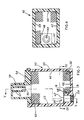
- a print head 1 comprises a support structure 10 fixed on a movable carriage 12 of a printer (not shown in the drawings but well known to those skilled in the art).
- a cavity or intermediate reservoir 16 which is open downwardly and closed upwardly by an end wall 18 of the structure 10.
- the structure 10 comprises four arms 20 to 23 connected to the end wall 18 and extending substantially in a direction perpendicular thereto; the arms 20 and 23 of the four arms are visible in the drawing.
- Each arm for example the arm 20 ( Figure 2), is formed by two elongate portions 24, 26 of two adjacent, mutually perpendicular side walls 24′ and 26′ of the structure 10.
- the walls 24′ and 26′ and two other side walls which are respectively parallel to and facing the walls 24′ and 26′ and of which only the wall 28′ is visible define a receiving space 30 for receiving an ink cartridge 32 ( Figure 1).
- the cartridge 32 can therefore be introduced into and removed from the space 30 by way of an opening 34 opposite to the end wall 18.
- the four arms 20-23 therefore perform the function of angular guides for the cartridge 32 during the operation of inserting it into the space 30.
- a tubular element 36 is fixed to the wall 18 to communicate the intermediate reservoir 16 with the space 30.
- the element 36 extends within the space 30 and has a pointed end 37 which is directed towards the opening 34.
- the element 35 closes the intermediate reservoir 16 downwardly in Figures 1 and 2 and is formed by a silicon plate 36 supporting a plurality of metal layers interposed between insulating layers and layers of resin, of the type described for example in our Italian patent application No.67044-A/89 filed January 26, 1989. More particularly the ink is projected on to the carrier 29 through a plurality of nozzles 45 (see Figure 2) communicating with corresponding expulsion chambers (not shown in the drawings) and provided in one of the insulating layers of the element 35.
- the expulsion chambers communicate with the intermediate reservoir 16 by way of a supply duct passing through the silicon plate 39.
- Electrical conductors of a flat cable 53 which is externally fixed to the support structure 10 are welded or soldered to the areas or pads on the plate 39.
- the cartridge 32 (see Figures 3 and 4) comprises a container 33 of substantially parallelepipedic shape and formed by four side walls 40, 41, 42, 43 which are fixed with respect to a front wall 44.
- an auxiliary space 46 disposed in a lateral position with respect to a longitudinal axis A-A of the cartridge 32 and delimited by the front wall 44, the side wall 42 and an internal wall 48 perpendicular to the wall 44.
- the space 46 on one side is open towards the interior of the cartridge 32 while on the opposite side it is closed by an element 50 of resilient material, for example soft rubber.
- the space 46, and the closure element 50 when the cartridge 32 is fitted into the support structure 10, are disposed in a position corresponding to the tubular element 36 which therefore perforates the element 50 and with its end 37 penetrates into the space 46 of the cartridge.
- the container 33 is filled with a spongy material 52 with communicating pores, the material being capable of being impregnated with ink.
- a metal grill 47 Disposed on the mouth opening 46′ of the auxiliary space 46 is a metal grill 47 for preventing the spongy material 52 from penetrating into the space 46.
- the container 33 After the container 33 has been filled with the sponge 52, the container 33 is closed with a cover 54 which is sealed to the edge of the walls 40-43, which is opposite to the wall 44.
- the cover 54 is provided with an opening 56 to the exterior to communicate the part of the sponge in contact with the cover 54 with external atmospheric pressure.
- the opening 56 comprises a conduit 57 extending towards the interior of the container 33 and disposed in a dome 58 projecting outwardly on the cover 54.
- the ink-filled cartridges can be preserved for a long period of time and in any position without any danger of loss of ink, in that the capillary action of the spongy material 52 retains the ink within the container 33.
- an ink-filled cartridge 32 is fitted into the space 30 ( Figure 2) of the support structure 10 in such a way that the end 37 of the tubular element 36 penetrates into the auxiliary space 46 ( Figure 1) after having perforated the closure element 50.
- the head 1 Before initiating the printing operation, the head 1 is moved to a suction station (not shown in the drawings) in which the ink contained in the cartridge 32 is sucked through the nozzles 45 (see Figure 2). In that way the ink forms in each nozzle a meniscus whose surface tension balances a depression created in the auxiliary space 46 ( Figure 1) and in the auxiliary reservoir 16 due to the effect of the capillary action of the spongy material 52. That depression is of the order of 1-5 cm water gauge when the head 1 is not operating while it can rise to 20-30 cm water gauge during the printing operation when a certain amount of ink is sucked in again from the reservoir 16 of the printing element 35 to replace the ink expelled from the nozzles 45.
- the use of a cartridge 32 for the ink, which is separate from the head 1, makes it possible to maintain the reservoir 16 and the printing element 35 empty of ink during the period of storage of the printer, thus ensuring that the nozzles are effective during subsequent operation of the printer.
- the cartridge 32 when already mounted on the head 1 may be removed and stored while the reservoir 16 and the nozzles 45 can be cleaned to remove the residual ink. That procedure avoids blockage of the nozzles by dried ink and minimises the risk of corrosion or infiltration of ink into the metal and insulating layers of the printing element 35 due to the prolonged presence of ink in contact with those layers.
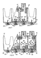
- the support structure 60 is capable of carrying for example four cartridges 62 of which only two cartridges are shown in the drawings for the sake of simplicity.
- Each cartridge is similar to the cartridge 32 in Figure 3 and contains an ink of a different color, for example black, magenta, cyan and blue.
- the support structure 60 comprises four intermediate reservoirs 161, 162, 163 and 164 corresponding to the four cartridges and similar to the reservoir 16 in Figure 2, each reservoir being provided with a tubular element 361-364 capable of perforated corresponding closure elements 502-503 of the cartridges 62.
- Each intermediate reservoir is closed at the bottom by the same number of printing elements 351-354 which are similar to the element 35 in Figure 2, wherein each printing element can print on the same printing carrier in succession with its own colored ink.
- Figure 8 shows a support structure 70 capable of accommodating a single cartridge 72 which is divided for example into a plurality of independent reservoirs or compartments, each filled with an ink of a different color.
- the structure 70 comprises an end wall 74 of rectangular shape provided with angular grooves 76 disposed at the four corners and capable of accommodating and guiding the cartridge 72.
- Each compartment 80 of the cartridge 72 is filled with a spongy material 95 capable of being impregnated with an ink of a different color.
- the printing elements 93 are aligned with each other and disposed parallel to the direction of forward movement of the head during the printing operation. In that way it is possible to effect printing selectively with each of the four colors or with different color shades, by emitting drops of ink of different colors in the same printing position.
- the cartridge 72 is closed upwardly by a cover 98 welded to the side walls and the separating walls 82 in such a way as completely to isolate the compartments 80 from each other. Conduits 89 disposed on the cover 98 communicate each compartment 80 with the external atmospheric pressure.
- the ink is expelled in the form of small drops through a plurality of nozzles communicating with corresponding explusion chambers for expulsion of the ink through the effect of rapid heating of heater elements contained in the expulsion chambers.
- the nozzles, the expulsion chambers, the heater elements and the associated electrical conductors are constructed in a plurality of metal layers and insulating layers supported by a silicon plate.
- the plate is fixed to the structure of the head and is supplied with ink contained in a removable cartridge fitted to the structure of the head.
- the cartridge comprises a rigid reservoir containing a sponge saturated with ink and can be hydraulically connected to the head by means of a needle-type conduit mounted on the head and which perforates a rubber membrane of the cartridge. During periods of storage and inactivity of the head, the cartridge can be removed, permitting drying of the nozzles so as to avoid possible nozzle blockages and corrosion of the layers of the plate by the ink.
- thermal ink jet print head illustrated is essentially free from the disadvantages discussed above in the introduction. More complete use of the printing plate is made for the whole of its period of effectiveness, keeping it free from ink during the periods of printing inactivity in order to minimise the risk of corrosion by the ink.
Abstract
Description
- The present invention relates to a thermal ink jet print head.
- A print head for a thermal ink jet printer is known in which a multi-layer print plate carrying the nozzles and electrical terminals for pilot control thereof is fixed to an end wall of a reservoir containing a spongy body impregnated with ink.
- The nozzles are hydraulically connected to the interior of the reservoir by way of a supply conduit passing through the plate and disposed at a position corresponding to an opening in the end wall of the reservoir. The electrical terminals of the print plate are soldered or welded to corresponding conductors of a flat cable fixed to the end wall on the outside of the reservoir. The flat cable carries conductive areas or pads which can be connected under the effect of pressure to corresponding fixed terminals of the printer.
- The reservoir with the plate which is fixed with respect thereto form an integrated printing and supply unit which is mounted removably on the carriage of the printer. When the ink is exhausted the integrated unit is replaced by another unit loaded with ink.
- As will be apparent, the ink always fills the nozzles and always remains in contact with the internal metal layers of the plate. During long periods of storage or inactivity of the integrated head, it may be found that the arrangement suffers from blockages of nozzles by virtue of drying of the ink or corrosion phenomena in respect of internal layers of the plate, with a consequential deterioration in the quality of printing and a reduction in the level of efficiency of the head itself. In addition since the life of a print head is much longer than the period for which the ink contained in the reservoir lasts, each time that the integrated unit is replaced, it is necessary to throw away a print plate which is still effective.
- The invention is defined in the appended claims to which reference may now be made.
- The invention will be more clearly apparent from the following description of a preferred embodiment given by way of non-limiting example with reference to the accompanying drawings, in which:
- Figure 1 is a view in section of a thermal ink jet print head embodying the invention,
- Figure 2 is a view in section of a support structure of the head shown in Figure 1,
- Figure 3 is a view in section of a cartridge for the ink used with the head in Figure 1,
- Figure 4 is a view in horizontal section taken along the line IV-IV in Figure 3,
- Figure 5 is a view in section taken along line V-V in Figure 3,
- Figure 6 is a view in section taken along dine VI-VI in Figure 2,
- Figure 7 is a view in longitudinal section of a multi-color head according to the invention, and
- Figure 8 is a view in longitudinal section of a multi-color print head having a single cartridge for inks of different colors.
- Referring to Figures 1 and 2 a print head 1 comprises a
support structure 10 fixed on amovable carriage 12 of a printer (not shown in the drawings but well known to those skilled in the art). - Provided in a
projection portion 14 of thestructure 10 is a cavity orintermediate reservoir 16 which is open downwardly and closed upwardly by anend wall 18 of thestructure 10. - The
structure 10 comprises fourarms 20 to 23 connected to theend wall 18 and extending substantially in a direction perpendicular thereto; thearms 20 and 23 of the four arms are visible in the drawing. Each arm, for example the arm 20 (Figure 2), is formed by twoelongate portions perpendicular side walls 24′ and 26′ of thestructure 10. Thewalls 24′ and 26′ and two other side walls which are respectively parallel to and facing thewalls 24′ and 26′ and of which only thewall 28′ is visible define areceiving space 30 for receiving an ink cartridge 32 (Figure 1). Thecartridge 32 can therefore be introduced into and removed from thespace 30 by way of an opening 34 opposite to theend wall 18. - The four arms 20-23 therefore perform the function of angular guides for the
cartridge 32 during the operation of inserting it into thespace 30. - A
tubular element 36 is fixed to thewall 18 to communicate theintermediate reservoir 16 with thespace 30. Theelement 36 extends within thespace 30 and has apointed end 37 which is directed towards theopening 34. - Fixed on the projection portion 14 (see Figure 1) is a thermal ink
jet print element 35 or print head of a type well-known in the art for printing dots on aprinting carrier 29. Theelement 35 closes theintermediate reservoir 16 downwardly in Figures 1 and 2 and is formed by asilicon plate 36 supporting a plurality of metal layers interposed between insulating layers and layers of resin, of the type described for example in our Italian patent application No.67044-A/89 filed January 26, 1989. More particularly the ink is projected on to thecarrier 29 through a plurality of nozzles 45 (see Figure 2) communicating with corresponding expulsion chambers (not shown in the drawings) and provided in one of the insulating layers of theelement 35. The expulsion chambers communicate with theintermediate reservoir 16 by way of a supply duct passing through thesilicon plate 39. Disposed on the outside face of theplate 39, which is directed towards theprinting carrier 29, are conductive areas or pads connected by way of one of the metal layers of theprint element 35 to heater elements (not shown) contained in the expulsion chambers. Electrical conductors of aflat cable 53 which is externally fixed to thesupport structure 10 are welded or soldered to the areas or pads on theplate 39. - The cartridge 32 (see Figures 3 and 4) comprises a
container 33 of substantially parallelepipedic shape and formed by fourside walls - Provided in the interior of the
container 33 is anauxiliary space 46 disposed in a lateral position with respect to a longitudinal axis A-A of thecartridge 32 and delimited by the front wall 44, theside wall 42 and aninternal wall 48 perpendicular to the wall 44. Thespace 46 on one side is open towards the interior of thecartridge 32 while on the opposite side it is closed by anelement 50 of resilient material, for example soft rubber. Thespace 46, and theclosure element 50 when thecartridge 32 is fitted into thesupport structure 10, are disposed in a position corresponding to thetubular element 36 which therefore perforates theelement 50 and with itsend 37 penetrates into thespace 46 of the cartridge. - The
container 33 is filled with aspongy material 52 with communicating pores, the material being capable of being impregnated with ink. Disposed on the mouth opening 46′ of theauxiliary space 46 is ametal grill 47 for preventing thespongy material 52 from penetrating into thespace 46. - After the
container 33 has been filled with thesponge 52, thecontainer 33 is closed with acover 54 which is sealed to the edge of the walls 40-43, which is opposite to the wall 44. - The
cover 54 is provided with anopening 56 to the exterior to communicate the part of the sponge in contact with thecover 54 with external atmospheric pressure. The opening 56 comprises aconduit 57 extending towards the interior of thecontainer 33 and disposed in adome 58 projecting outwardly on thecover 54. - The
cartridge 32 is filled with ink for example by drawing air from the conduit 56 (see Figure 3) and introducing ink from the bottom through theclosure 50 by means of a needle tube similar to thetube 36 in Figure 2 and communicating with an ink reservoir (not shown in the drawings). The cartridge is loaded when the ink has filled theauxiliary space 46 and has completely impregnated thespongy material 52. - The ink-filled cartridges can be preserved for a long period of time and in any position without any danger of loss of ink, in that the capillary action of the
spongy material 52 retains the ink within thecontainer 33. - In order to initiate a printing operation, an ink-filled
cartridge 32 is fitted into the space 30 (Figure 2) of thesupport structure 10 in such a way that theend 37 of thetubular element 36 penetrates into the auxiliary space 46 (Figure 1) after having perforated theclosure element 50. - Before initiating the printing operation, the head 1 is moved to a suction station (not shown in the drawings) in which the ink contained in the
cartridge 32 is sucked through the nozzles 45 (see Figure 2). In that way the ink forms in each nozzle a meniscus whose surface tension balances a depression created in the auxiliary space 46 (Figure 1) and in theauxiliary reservoir 16 due to the effect of the capillary action of thespongy material 52. That depression is of the order of 1-5 cm water gauge when the head 1 is not operating while it can rise to 20-30 cm water gauge during the printing operation when a certain amount of ink is sucked in again from thereservoir 16 of theprinting element 35 to replace the ink expelled from thenozzles 45. The use of acartridge 32 for the ink, which is separate from the head 1, makes it possible to maintain thereservoir 16 and theprinting element 35 empty of ink during the period of storage of the printer, thus ensuring that the nozzles are effective during subsequent operation of the printer. - In addition in the event of an interruption in activity of the printer the
cartridge 32 when already mounted on the head 1 may be removed and stored while thereservoir 16 and thenozzles 45 can be cleaned to remove the residual ink. That procedure avoids blockage of the nozzles by dried ink and minimises the risk of corrosion or infiltration of ink into the metal and insulating layers of theprinting element 35 due to the prolonged presence of ink in contact with those layers. - The head 1 can also be used for multi-colour printing. Referring to Figure 7, a
support structure 60 may contain a plurality ofcartridge 62 containing inks of different colors. - The
support structure 60 is capable of carrying for example fourcartridges 62 of which only two cartridges are shown in the drawings for the sake of simplicity. Each cartridge is similar to thecartridge 32 in Figure 3 and contains an ink of a different color, for example black, magenta, cyan and blue. - The
support structure 60 comprises fourintermediate reservoirs reservoir 16 in Figure 2, each reservoir being provided with a tubular element 361-364 capable of perforated corresponding closure elements 502-503 of thecartridges 62. Each intermediate reservoir is closed at the bottom by the same number of printing elements 351-354 which are similar to theelement 35 in Figure 2, wherein each printing element can print on the same printing carrier in succession with its own colored ink. - Figure 8 shows a
support structure 70 capable of accommodating asingle cartridge 72 which is divided for example into a plurality of independent reservoirs or compartments, each filled with an ink of a different color. - The
structure 70 comprises anend wall 74 of rectangular shape provided withangular grooves 76 disposed at the four corners and capable of accommodating and guiding thecartridge 72. - The
cartridge 72 is formed by acontainer 78 of parallelepipedic shape and divided for example into fourseparate compartments 80 bywalls 82. Disposed on the bottom 84 of each compartment is achamber 86 for collecting the ink, which is delimited by acylindrical wall 88 and which is open towards the interior of the same compartment by way of agrill 87. Thechamber 86 is also closed by aclosure element 90 passing through the bottom 84 and formed from soft rubber. Disposed on thewall 74 at a position corresponding to eachelement 90 aretubes 92 having a pointed end, the tubes being capable of perforating theelements 90 and penetrating into thechambers 86 when thecartridge 72 is fitted to thestructure 70. Thetubes 92 communicate withauxiliary reservoirs 94 provided inexternal projection portions 96 on thebottom wall 74. Eachreservoir 94 is closed by a thermal inkjet printing element 93 of the type described hereinbefore. - Each
compartment 80 of thecartridge 72 is filled with aspongy material 95 capable of being impregnated with an ink of a different color. - The
printing elements 93 are aligned with each other and disposed parallel to the direction of forward movement of the head during the printing operation. In that way it is possible to effect printing selectively with each of the four colors or with different color shades, by emitting drops of ink of different colors in the same printing position. Thecartridge 72 is closed upwardly by acover 98 welded to the side walls and the separatingwalls 82 in such a way as completely to isolate thecompartments 80 from each other.Conduits 89 disposed on thecover 98 communicate eachcompartment 80 with the external atmospheric pressure. - Thus, in summary, in the thermal ink jet print head illustrated the ink is expelled in the form of small drops through a plurality of nozzles communicating with corresponding explusion chambers for expulsion of the ink through the effect of rapid heating of heater elements contained in the expulsion chambers. The nozzles, the expulsion chambers, the heater elements and the associated electrical conductors are constructed in a plurality of metal layers and insulating layers supported by a silicon plate. The plate is fixed to the structure of the head and is supplied with ink contained in a removable cartridge fitted to the structure of the head. The cartridge comprises a rigid reservoir containing a sponge saturated with ink and can be hydraulically connected to the head by means of a needle-type conduit mounted on the head and which perforates a rubber membrane of the cartridge. During periods of storage and inactivity of the head, the cartridge can be removed, permitting drying of the nozzles so as to avoid possible nozzle blockages and corrosion of the layers of the plate by the ink.
- The thermal ink jet print head illustrated is essentially free from the disadvantages discussed above in the introduction. More complete use of the printing plate is made for the whole of its period of effectiveness, keeping it free from ink during the periods of printing inactivity in order to minimise the risk of corrosion by the ink.
- It will be appreciated that modifications, additions or substitution of parts and/or variations in form may be made in the print head according to the present invention without thereby departing from the scope of the invention.
Claims (9)
Applications Claiming Priority (2)
| Application Number | Priority Date | Filing Date | Title |
|---|---|---|---|
| IT8967585A IT1232551B (en) | 1989-07-13 | 1989-07-13 | PRINT HEAD FOR A INK-JET THERMAL PRINTER |
| IT6758589 | 1989-07-13 |
Publications (3)
| Publication Number | Publication Date |
|---|---|
| EP0408241A2 true EP0408241A2 (en) | 1991-01-16 |
| EP0408241A3 EP0408241A3 (en) | 1991-06-12 |
| EP0408241B1 EP0408241B1 (en) | 1994-10-19 |
Family
ID=11303642
Family Applications (1)
| Application Number | Title | Priority Date | Filing Date |
|---|---|---|---|
| EP90307312A Expired - Lifetime EP0408241B1 (en) | 1989-07-13 | 1990-07-04 | Print head for a thermal ink jet printer |
Country Status (5)
| Country | Link |
|---|---|
| US (1) | US5119115A (en) |
| EP (1) | EP0408241B1 (en) |
| JP (1) | JP2997017B2 (en) |
| DE (1) | DE69013419T2 (en) |
| IT (1) | IT1232551B (en) |
Cited By (36)
| Publication number | Priority date | Publication date | Assignee | Title |
|---|---|---|---|---|
| US5119115A (en) * | 1989-07-13 | 1992-06-02 | Ing. C. Olivetti & C. S.P.A. | Thermal ink jet print head with removable ink cartridge |
| DE4201923A1 (en) * | 1991-01-28 | 1992-08-06 | Fuji Electric Co Ltd | Ink-jet printing head - has ink nozzles placed close together on single silicon substrate, with ink flow channels formed in substrate by dry-plasma etching |
| EP0509747A1 (en) * | 1991-04-15 | 1992-10-21 | Ing. C. Olivetti & C., S.p.A. | Ink detecting device for a liquid-ink printing element |
| EP0553535A1 (en) * | 1992-01-28 | 1993-08-04 | Seiko Epson Corporation | Ink tank cartridge and container therefor |
| EP0633138A2 (en) * | 1993-07-06 | 1995-01-11 | Brother Kogyo Kabushiki Kaisha | Ink supply device |
| EP0638427A2 (en) * | 1993-08-13 | 1995-02-15 | PMS GmbH, Produktion + Recycling von Büromaschinenzubehör | Apparatus, kit and method for filling a printhead of an ink jet printer |
| EP0639462A2 (en) * | 1993-08-19 | 1995-02-22 | Canon Kabushiki Kaisha | Ink tank cartridge and ink-jet apparatus in which the ink tank cartridge is installed |
| EP0645243A2 (en) * | 1993-09-23 | 1995-03-29 | OLIVETTI-CANON INDUSTRIALE S.p.A. | Refillable ink jet printing module |
| EP0726154A2 (en) * | 1995-02-07 | 1996-08-14 | Canon Kabushiki Kaisha | Method for positioning an ink cartridge, and the ink cartridge and ink jet recording apparatus used for such method |
| GB2298616A (en) * | 1992-07-31 | 1996-09-11 | Canon Kk | Liquid storing container for a recording apparatus |
| EP0737584A2 (en) * | 1995-04-10 | 1996-10-16 | Fuji Xerox Co., Ltd. | Ink tank and recording apparatus |
| EP0755794A2 (en) * | 1995-07-24 | 1997-01-29 | Canon Kabushiki Kaisha | Ink tank structure |
| EP0756937A2 (en) * | 1995-08-01 | 1997-02-05 | Brother Kogyo Kabushiki Kaisha | Connecting structure for printing head and ink cartridge |
| US5642144A (en) * | 1994-11-29 | 1997-06-24 | Hewlett-Packard Company | Rechargeable pen for printer |
| AU680523B2 (en) * | 1993-08-31 | 1997-07-31 | Canon Kabushiki Kaisha | Ink filling method and apparatus for ink cartridge |
| US5680164A (en) * | 1994-11-29 | 1997-10-21 | Hewlett-Packard Company | Refill method and apparatus for ink cartridge units |
| US5699095A (en) * | 1993-02-02 | 1997-12-16 | Seiko Epson Corporation | Ink-jet recording apparatus |
| EP0850766A2 (en) * | 1993-11-29 | 1998-07-01 | Canon Kabushiki Kaisha | Improved ink container, installing-removing method therefore, and apparatus usable with the same |
| US5790158A (en) * | 1992-01-28 | 1998-08-04 | Seiko Epson Corporation | Ink-jet recording apparatus and ink tank cartridge therefor |
| AU701231B2 (en) * | 1993-08-19 | 1999-01-21 | Canon Kabushiki Kaisha | Ink tank cartridge and ink-jet apparatus installed in the ink tank cartridge |
| FR2773102A1 (en) * | 1996-06-25 | 1999-07-02 | Seiko Epson Corp | INK CARTRIDGE FOR COLOR PRINTING |
| EP0888893A3 (en) * | 1997-06-30 | 1999-11-03 | Olivetti Lexikon S.p.A. | Colour ink-jet print head |
| US6003985A (en) * | 1991-12-11 | 1999-12-21 | Canon Kabushiki Kaisha | Ink jet recording apparatus |
| US6045207A (en) * | 1990-01-30 | 2000-04-04 | Seiko Epson Corporation | Ink-jet recording apparatus and ink tank cartridge therefor |
| US6145974A (en) * | 1983-10-13 | 2000-11-14 | Seiko Epson Corporation | Ink-supplied printer head and ink container |
| US6170939B1 (en) | 1992-07-31 | 2001-01-09 | Canon Kabushiki Kaisha | Liquid storing container for recording apparatus |
| US6170941B1 (en) | 1997-03-07 | 2001-01-09 | Seiko Epson Corporation | Ink cartridge for ink-jet recorder |
| US6247803B1 (en) | 1983-10-13 | 2001-06-19 | Seiko Epson Corporation | Ink jet recording apparatus and method for replenishing ink in the tank cartridge |
| US6276785B1 (en) | 1983-10-13 | 2001-08-21 | Seiko Epson Corporation | Ink-supplied printer head and ink container |
| US6474798B1 (en) | 1984-10-11 | 2002-11-05 | Seiko Epson Corporation | Ink supplied printer head and ink container |
| US6854835B2 (en) | 1994-09-16 | 2005-02-15 | Seiko Epson Corporation | Ink cartridge for ink jet printer and method of charging ink into said cartridge |
| DE19727077B4 (en) * | 1996-06-25 | 2006-04-06 | Seiko Epson Corp. | Ink cartridge, ink cartridge mounting device, detection plates of an ink end detector, and method of attaching an ink cartridge |
| WO2008074210A1 (en) * | 2006-12-18 | 2008-06-26 | Chunyun Liu | A printhead-equipped and split-type ink cartridge |
| US7401909B2 (en) | 1994-08-24 | 2008-07-22 | Canon Kabushiki Kaisha | Ink container for ink jet printer, holder for the container, carriage for the holder and ink jet printer |
| EP1867484B1 (en) | 1998-05-18 | 2010-03-24 | Seiko Epson Corporation | Ink- jet printing apparatus and ink cartridge therefor |
| US8421869B2 (en) | 1997-07-15 | 2013-04-16 | Google Inc. | Camera system for with velocity sensor and de-blurring processor |
Families Citing this family (84)
| Publication number | Priority date | Publication date | Assignee | Title |
|---|---|---|---|---|
| US5328279A (en) | 1984-05-22 | 1994-07-12 | Seiko Epson Corporation | Dot matrix printer head |
| DK0419192T3 (en) * | 1989-09-18 | 1994-05-24 | Canon Kk | Inkjet head and inkjet recorder |
| US5461405A (en) * | 1989-10-30 | 1995-10-24 | Eastman Kodak Company | Ink jet printer device with exchangeable printheads |
| US5488401A (en) * | 1991-01-18 | 1996-01-30 | Seiko Epson Corporation | Ink-jet recording apparatus and ink tank cartridge thereof |
| US5477963A (en) * | 1992-01-28 | 1995-12-26 | Seiko Epson Corporation | Ink-jet recording apparatus and ink tank cartridge therefor |
| DE9203206U1 (en) * | 1992-03-10 | 1992-05-21 | Franz Buettner Ag, Egg, Ch | |
| US5359357A (en) * | 1992-03-19 | 1994-10-25 | Fuji Xerox Co., Ltd. | Ink-jet recording apparatus |
| JP2962044B2 (en) * | 1992-05-29 | 1999-10-12 | 富士ゼロックス株式会社 | Ink tank, inkjet cartridge, and inkjet recording device |
| US5619238A (en) | 1992-07-24 | 1997-04-08 | Canon Kabushiki Kaisha | Method of making replaceable ink cartridge |
| CA2290698C (en) * | 1992-07-24 | 2003-12-23 | Canon Kabushiki Kaisha | Ink container, ink and ink jet recording apparatus using ink container |
| US6332675B1 (en) | 1992-07-24 | 2001-12-25 | Canon Kabushiki Kaisha | Ink container, ink and ink jet recording apparatus using ink container |
| JP3011830B2 (en) * | 1992-08-10 | 2000-02-21 | キヤノン株式会社 | Ink jet printing method and printed matter |
| US5574490A (en) * | 1992-08-12 | 1996-11-12 | Hewlett-Packard Company | Ink jet hard copy apparatus ink cartridge |
| JP3253153B2 (en) | 1992-10-20 | 2002-02-04 | キヤノン株式会社 | Ink jet head cartridge and ink jet apparatus provided with the cartridge |
| JP2839997B2 (en) * | 1992-12-09 | 1998-12-24 | 株式会社リコー | Recording head unit |
| JP3188056B2 (en) * | 1993-07-21 | 2001-07-16 | キヤノン株式会社 | Ink jet recording device and ink jet head |
| US6007191A (en) * | 1993-08-19 | 1999-12-28 | Fuji Xerox Co., Ltd. | Ink supply unit |
| DE69430345T2 (en) | 1993-08-23 | 2002-10-10 | Canon Kk | Interchangeable ink cartridge |
| JP3183760B2 (en) * | 1993-10-04 | 2001-07-09 | キヤノン株式会社 | Ink container, inkjet recording head, inkjet cartridge, and inkjet recording apparatus |
| US5949461A (en) * | 1994-02-18 | 1999-09-07 | Nu-Kote Imaging International, Inc. | Ink refill bottle |
| DE9405723U1 (en) * | 1994-04-06 | 1994-06-01 | Pelikan Produktions Ag Egg | Ink cartridge for a printhead of an ink jet printer |
| EP0699532B1 (en) * | 1994-08-31 | 2000-06-28 | Canon Kabushiki Kaisha | Ink jet refilling method and apparatus for ink container |
| CN101081563B (en) * | 1994-09-16 | 2011-10-05 | 精工爱普生株式会社 | Ink tank cartridge for a printer |
| US5596358A (en) * | 1994-10-31 | 1997-01-21 | Hewlett-Packard Company | Method and apparatus for refilling a print cartridge having a reservoir pressure of less than ambient pressure |
| US5576750A (en) * | 1994-10-11 | 1996-11-19 | Lexmark International, Inc. | Reliable connecting pathways for a three-color ink-jet cartridge |
| USD378760S (en) * | 1994-10-24 | 1997-04-08 | Seiko Epson Corporation | Ink cartridge for printer |
| USD381039S (en) * | 1994-10-24 | 1997-07-15 | Seiko Epson Corporation | Ink cartridge for printer |
| US5663753A (en) * | 1994-11-14 | 1997-09-02 | Jetfill, Inc. | Recording cartridge with replaceable liquid-containing reservoir |
| JPH07186451A (en) * | 1994-11-17 | 1995-07-25 | Ricoh Co Ltd | Ink jet recording device |
| JP2817656B2 (en) * | 1995-02-21 | 1998-10-30 | 富士ゼロックス株式会社 | Ink supply device and recording device |
| US5900896A (en) * | 1995-04-27 | 1999-05-04 | Hewlett-Packard Company | Ink cartridge adapters |
| US6183077B1 (en) | 1995-04-27 | 2001-02-06 | Hewlett-Packard Company | Method and apparatus for keying ink supply containers |
| USD382296S (en) * | 1995-05-10 | 1997-08-12 | Seiko Epson Corporation | Ink cartridge for printer |
| JP2814952B2 (en) * | 1995-05-18 | 1998-10-27 | 富士ゼロックス株式会社 | Ink holding material, method for producing the same, ink jet recording apparatus and ink jet recording method |
| JP3227388B2 (en) * | 1995-08-02 | 2001-11-12 | キヤノン株式会社 | Ink absorber, ink tank using the ink absorber, inkjet cartridge integrating ink tank and inkjet recording head, method of manufacturing ink tank, and fiber mass used in the ink tank |
| US6027208A (en) * | 1995-09-29 | 2000-02-22 | Rohm Co. Ltd. | Ink jet printhead with passage forming panel and vibration plate |
| IT235963Y1 (en) * | 1995-10-23 | 2000-07-18 | Baltea Spa | CONTAINER TO RECHARGE AN INK-JET PRINT HEAD. |
| US5900895A (en) | 1995-12-04 | 1999-05-04 | Hewlett-Packard Company | Method for refilling an ink supply for an ink-jet printer |
| US5732751A (en) | 1995-12-04 | 1998-03-31 | Hewlett-Packard Company | Filling ink supply containers |
| US5880764A (en) * | 1995-12-04 | 1999-03-09 | Hewlett-Packard Company | Adaptive ink supply for an ink-jet printer |
| US5847734A (en) | 1995-12-04 | 1998-12-08 | Pawlowski, Jr.; Norman E. | Air purge system for an ink-jet printer |
| US5815182A (en) | 1995-12-04 | 1998-09-29 | Hewlett-Packard Company | Fluid interconnect for ink-jet pen |
| US5771053A (en) | 1995-12-04 | 1998-06-23 | Hewlett-Packard Company | Assembly for controlling ink release from a container |
| US5751322A (en) * | 1996-02-13 | 1998-05-12 | Hewlett-Packard Company | Limited access needle/septum ink-supply interface mechanism |
| JP3039358B2 (en) * | 1996-02-21 | 2000-05-08 | 富士ゼロックス株式会社 | Ink supply device and recording device |
| WO1997042035A1 (en) * | 1996-05-06 | 1997-11-13 | Graphic Utilities, Inc. | Auxiliary ink reservoir and feed system and method for ink jet cartridges |
| AU728998B2 (en) * | 1996-07-08 | 2001-01-25 | Corning Incorporated | Rayleigh-breakup atomizing devices and methods of making rayleigh-breakup atomizing devices |
| AU729427B2 (en) | 1996-07-08 | 2001-02-01 | Corning Incorporated | Gas-assisted atomizing device |
| US6352209B1 (en) | 1996-07-08 | 2002-03-05 | Corning Incorporated | Gas assisted atomizing devices and methods of making gas-assisted atomizing devices |
| US5901425A (en) | 1996-08-27 | 1999-05-11 | Topaz Technologies Inc. | Inkjet print head apparatus |
| US6786420B1 (en) | 1997-07-15 | 2004-09-07 | Silverbrook Research Pty. Ltd. | Data distribution mechanism in the form of ink dots on cards |
| KR100209513B1 (en) | 1997-04-22 | 1999-07-15 | 윤종용 | Active liquid containing and supplying apparatus in inkjet print head |
| US6803989B2 (en) | 1997-07-15 | 2004-10-12 | Silverbrook Research Pty Ltd | Image printing apparatus including a microcontroller |
| US6618117B2 (en) | 1997-07-12 | 2003-09-09 | Silverbrook Research Pty Ltd | Image sensing apparatus including a microcontroller |
| AUPO802797A0 (en) | 1997-07-15 | 1997-08-07 | Silverbrook Research Pty Ltd | Image processing method and apparatus (ART54) |
| SG121714A1 (en) * | 1997-07-15 | 2006-05-26 | Silverbrook Res Pty Ltd | Production of artistic effects in images utilisingretricted gamut spaces |
| US7551201B2 (en) | 1997-07-15 | 2009-06-23 | Silverbrook Research Pty Ltd | Image capture and processing device for a print on demand digital camera system |
| US6624848B1 (en) | 1997-07-15 | 2003-09-23 | Silverbrook Research Pty Ltd | Cascading image modification using multiple digital cameras incorporating image processing |
| AUPO850597A0 (en) | 1997-08-11 | 1997-09-04 | Silverbrook Research Pty Ltd | Image processing method and apparatus (art01a) |
| US6985207B2 (en) | 1997-07-15 | 2006-01-10 | Silverbrook Research Pty Ltd | Photographic prints having magnetically recordable media |
| US6820968B2 (en) * | 1997-07-15 | 2004-11-23 | Silverbrook Research Pty Ltd | Fluid-dispensing chip |
| US7705891B2 (en) | 1997-07-15 | 2010-04-27 | Silverbrook Research Pty Ltd | Correction of distortions in digital images |
| US6217165B1 (en) * | 1997-07-15 | 2001-04-17 | Silverbrook Research Pty. Ltd. | Ink and media cartridge with axial ink chambers |
| US6690419B1 (en) | 1997-07-15 | 2004-02-10 | Silverbrook Research Pty Ltd | Utilising eye detection methods for image processing in a digital image camera |
| US6879341B1 (en) | 1997-07-15 | 2005-04-12 | Silverbrook Research Pty Ltd | Digital camera system containing a VLIW vector processor |
| AUPP702098A0 (en) | 1998-11-09 | 1998-12-03 | Silverbrook Research Pty Ltd | Image creation method and apparatus (ART73) |
| AUPQ056099A0 (en) | 1999-05-25 | 1999-06-17 | Silverbrook Research Pty Ltd | A method and apparatus (pprint01) |
| US6398354B1 (en) | 1999-06-30 | 2002-06-04 | Lexmark International, Inc. | Printhead apparatus and printer having separate filtration device and method for attaching said device |
| US6270211B1 (en) | 1999-07-07 | 2001-08-07 | Lexmark International, Inc. | Bubble elimination and filter tower structure |
| US6655785B1 (en) * | 1999-08-25 | 2003-12-02 | Xerox Corporation | Print element and method for assembling a print head |
| DE19951090B4 (en) * | 1999-10-23 | 2005-02-24 | Tally Computerdrucker Gmbh | Ink printer with an ink print head on a reciprocating carriage and with an ink capillary memory connected to the ink print head |
| WO2002028647A1 (en) | 2000-10-06 | 2002-04-11 | Nu-Kote International, Inc. | Septum seal plug used in inkjet cartridge |
| TWI259149B (en) * | 2002-09-30 | 2006-08-01 | Canon Kk | Ink container and recording apparatus |
| TW577823B (en) * | 2003-04-09 | 2004-03-01 | Benq Corp | Ink-jet cartridge |
| ATE333371T1 (en) | 2003-11-19 | 2006-08-15 | 3T Supplies Ag | INK CARTRIDGE, INK CARTRIDGE UNIT AND INKJET PRINTHEAD |
| JP4404210B2 (en) * | 2005-03-10 | 2010-01-27 | ブラザー工業株式会社 | Image recording device |
| US20070035596A1 (en) * | 2005-08-10 | 2007-02-15 | Lexmark International, Inc. | Ink jet cartridge |
| JP4609666B2 (en) * | 2006-03-31 | 2011-01-12 | ブラザー工業株式会社 | Protection device for ink cartridge storage device |
| JP2007276222A (en) * | 2006-04-05 | 2007-10-25 | Brother Ind Ltd | Ink cartridge fitting method, ink cartridge and inkjet printer |
| US20090228463A1 (en) * | 2008-03-10 | 2009-09-10 | Cramer Richard D | Method for Searching Compound Databases Using Topomeric Shape Descriptors and Pharmacophoric Features Identified by a Comparative Molecular Field Analysis (CoMFA) Utilizing Topomeric Alignment of Molecular Fragments |
| EP2344337B1 (en) * | 2008-10-15 | 2013-09-25 | Hewlett-Packard Development Company, L.P. | Fluid ejection cartridge |
| TW201114613A (en) * | 2009-10-29 | 2011-05-01 | Fieldct Inc | Ink cartridge compatible with jet painting machine |
| US8256876B2 (en) * | 2010-03-31 | 2012-09-04 | Eastman Kodak Company | Ink passageways connecting inlet ports and chambers |
| DE102019116103B4 (en) * | 2019-06-13 | 2021-04-22 | Notion Systems GmbH | Method for labeling a printed circuit board by creating shading in a functional lacquer layer |
Citations (4)
| Publication number | Priority date | Publication date | Assignee | Title |
|---|---|---|---|---|
| GB2017006A (en) * | 1978-03-22 | 1979-10-03 | Siemens Ag | Ink supply arrangement for printing apparatus |
| US4700202A (en) * | 1983-02-23 | 1987-10-13 | Sharp Kabushiki Kaisha | Ink cartridge in an ink jet system printer |
| US4771295A (en) * | 1986-07-01 | 1988-09-13 | Hewlett-Packard Company | Thermal ink jet pen body construction having improved ink storage and feed capability |
| US4878069A (en) * | 1984-07-09 | 1989-10-31 | Canon Kabushiki Kaisha | Ink jet recording apparatus with an ink tank-carriage configuration for increasing useable space |
Family Cites Families (6)
| Publication number | Priority date | Publication date | Assignee | Title |
|---|---|---|---|---|
| JPS5656877A (en) * | 1979-10-17 | 1981-05-19 | Canon Inc | Ink jet recording apparatus |
| DE3171562D1 (en) * | 1980-06-06 | 1985-09-05 | Epson Corp | Ink supply system for a printer |
| IT1179973B (en) * | 1984-02-15 | 1987-09-23 | Olivetti & Co Spa | SELECTIVE JET INK PRINT HEAD AND INK CARTRIDGE FOR SUCH HEAD |
| US4633274A (en) * | 1984-03-30 | 1986-12-30 | Canon Kabushiki Kaisha | Liquid ejection recording apparatus |
| JP2558103B2 (en) * | 1986-07-31 | 1996-11-27 | キヤノン株式会社 | Ink supply device |
| IT1232551B (en) * | 1989-07-13 | 1992-02-19 | Olivetti & Co Spa | PRINT HEAD FOR A INK-JET THERMAL PRINTER |
-
1989
- 1989-07-13 IT IT8967585A patent/IT1232551B/en active
-
1990
- 1990-06-25 US US07/542,908 patent/US5119115A/en not_active Expired - Lifetime
- 1990-07-04 EP EP90307312A patent/EP0408241B1/en not_active Expired - Lifetime
- 1990-07-04 DE DE69013419T patent/DE69013419T2/en not_active Expired - Lifetime
- 1990-07-13 JP JP2186990A patent/JP2997017B2/en not_active Expired - Lifetime
Patent Citations (5)
| Publication number | Priority date | Publication date | Assignee | Title |
|---|---|---|---|---|
| GB2017006A (en) * | 1978-03-22 | 1979-10-03 | Siemens Ag | Ink supply arrangement for printing apparatus |
| US4700202A (en) * | 1983-02-23 | 1987-10-13 | Sharp Kabushiki Kaisha | Ink cartridge in an ink jet system printer |
| US4878069A (en) * | 1984-07-09 | 1989-10-31 | Canon Kabushiki Kaisha | Ink jet recording apparatus with an ink tank-carriage configuration for increasing useable space |
| US4771295A (en) * | 1986-07-01 | 1988-09-13 | Hewlett-Packard Company | Thermal ink jet pen body construction having improved ink storage and feed capability |
| US4771295B1 (en) * | 1986-07-01 | 1995-08-01 | Hewlett Packard Co | Thermal ink jet pen body construction having improved ink storage and feed capability |
Cited By (78)
| Publication number | Priority date | Publication date | Assignee | Title |
|---|---|---|---|---|
| US6145974A (en) * | 1983-10-13 | 2000-11-14 | Seiko Epson Corporation | Ink-supplied printer head and ink container |
| US6247803B1 (en) | 1983-10-13 | 2001-06-19 | Seiko Epson Corporation | Ink jet recording apparatus and method for replenishing ink in the tank cartridge |
| US6276785B1 (en) | 1983-10-13 | 2001-08-21 | Seiko Epson Corporation | Ink-supplied printer head and ink container |
| US6474798B1 (en) | 1984-10-11 | 2002-11-05 | Seiko Epson Corporation | Ink supplied printer head and ink container |
| US5119115A (en) * | 1989-07-13 | 1992-06-02 | Ing. C. Olivetti & C. S.P.A. | Thermal ink jet print head with removable ink cartridge |
| US6045207A (en) * | 1990-01-30 | 2000-04-04 | Seiko Epson Corporation | Ink-jet recording apparatus and ink tank cartridge therefor |
| DE4201923A1 (en) * | 1991-01-28 | 1992-08-06 | Fuji Electric Co Ltd | Ink-jet printing head - has ink nozzles placed close together on single silicon substrate, with ink flow channels formed in substrate by dry-plasma etching |
| EP0509747A1 (en) * | 1991-04-15 | 1992-10-21 | Ing. C. Olivetti & C., S.p.A. | Ink detecting device for a liquid-ink printing element |
| US5289211A (en) * | 1991-04-15 | 1994-02-22 | Ing. S. Olivetti & C., S.p.A. | Ink detecting device for a liquid-ink printing element |
| US6003985A (en) * | 1991-12-11 | 1999-12-21 | Canon Kabushiki Kaisha | Ink jet recording apparatus |
| US6070975A (en) * | 1991-12-11 | 2000-06-06 | Canon Kabushiki Kaisha | Ink jet recording apparatus and a method for installing ink jet recording head |
| EP0553535A1 (en) * | 1992-01-28 | 1993-08-04 | Seiko Epson Corporation | Ink tank cartridge and container therefor |
| US5790158A (en) * | 1992-01-28 | 1998-08-04 | Seiko Epson Corporation | Ink-jet recording apparatus and ink tank cartridge therefor |
| EP1905599A3 (en) * | 1992-01-28 | 2009-04-08 | Seiko Epson Corporation | Ink tank cartridge and container therefor |
| EP1013444A1 (en) * | 1992-01-28 | 2000-06-28 | Seiko Epson Corporation | Ink tank cartridge and container therefor |
| EP0786352A1 (en) * | 1992-01-28 | 1997-07-30 | Seiko Epson Corporation | Ink tank cartridge and container therefor |
| EP1241012A3 (en) * | 1992-01-28 | 2003-01-02 | Seiko Epson Corporation | Ink tank cartridge and container therefor |
| GB2298616A (en) * | 1992-07-31 | 1996-09-11 | Canon Kk | Liquid storing container for a recording apparatus |
| EP0779158A3 (en) * | 1992-07-31 | 1997-07-02 | Canon Kabushiki Kaisha | Liquid storing container for recording apparatus |
| US5583549A (en) * | 1992-07-31 | 1996-12-10 | Canon Kabushiki Kaisha | Liquid storing container for recording apparatus |
| US6170939B1 (en) | 1992-07-31 | 2001-01-09 | Canon Kabushiki Kaisha | Liquid storing container for recording apparatus |
| GB2298616B (en) * | 1992-07-31 | 1997-03-19 | Canon Kk | Liquid storing container for recording apparatus |
| GB2269784B (en) * | 1992-07-31 | 1997-03-19 | Canon Kk | Liquid storing container for recording apparatus |
| US5781213A (en) * | 1992-07-31 | 1998-07-14 | Canon Kabushiki Kaisha | Liquid storing container having filter interface for recording apparatus |
| US5589862A (en) * | 1992-07-31 | 1996-12-31 | Canon Kabushiki Kaisha | Liquid storing container for recording apparatus |
| US5699095A (en) * | 1993-02-02 | 1997-12-16 | Seiko Epson Corporation | Ink-jet recording apparatus |
| EP0633138A3 (en) * | 1993-07-06 | 1995-06-28 | Brother Ind Ltd | Ink supply device. |
| EP0633138A2 (en) * | 1993-07-06 | 1995-01-11 | Brother Kogyo Kabushiki Kaisha | Ink supply device |
| US5631682A (en) * | 1993-07-06 | 1997-05-20 | Brother Kogyo Kabushiki Kaisha | Printhead ink supply device |
| EP0638427A3 (en) * | 1993-08-13 | 1995-09-06 | Pms Gmbh Prod & Recycling | Apparatus, kit and method for filling a printhead of an ink jet printer. |
| EP0638427A2 (en) * | 1993-08-13 | 1995-02-15 | PMS GmbH, Produktion + Recycling von Büromaschinenzubehör | Apparatus, kit and method for filling a printhead of an ink jet printer |
| CN1086637C (en) * | 1993-08-19 | 2002-06-26 | 佳能株式会社 | Ink tank cartridge and ink-jet apparatus instalied the ink tank cartridge |
| US6179415B1 (en) | 1993-08-19 | 2001-01-30 | Canon Kabushiki Kaisha | Ink tank cartridge |
| EP0931660A3 (en) * | 1993-08-19 | 1999-11-24 | Canon Kabushiki Kaisha | Ink tank cartridge and ink-jet apparatus in which the ink tank cartridge is installed |
| EP0639462A3 (en) * | 1993-08-19 | 1995-10-18 | Canon Kk | Ink tank cartridge and ink-jet apparatus in which the ink tank cartridge is installed. |
| AU701231B2 (en) * | 1993-08-19 | 1999-01-21 | Canon Kabushiki Kaisha | Ink tank cartridge and ink-jet apparatus installed in the ink tank cartridge |
| EP0639462A2 (en) * | 1993-08-19 | 1995-02-22 | Canon Kabushiki Kaisha | Ink tank cartridge and ink-jet apparatus in which the ink tank cartridge is installed |
| EP0931660A2 (en) * | 1993-08-19 | 1999-07-28 | Canon Kabushiki Kaisha | Ink tank cartridge and ink-jet apparatus in which the ink tank cartridge is installed |
| AU680523B2 (en) * | 1993-08-31 | 1997-07-31 | Canon Kabushiki Kaisha | Ink filling method and apparatus for ink cartridge |
| US5555007A (en) * | 1993-09-23 | 1996-09-10 | Olivetti-Canon Industriale, S.P.A. | Refillable ink jet printing module |
| EP0645243A3 (en) * | 1993-09-23 | 1995-08-16 | Olivetti Canon Ind Spa | Refillable ink jet printing module. |
| EP0645243A2 (en) * | 1993-09-23 | 1995-03-29 | OLIVETTI-CANON INDUSTRIALE S.p.A. | Refillable ink jet printing module |
| EP0856405A1 (en) * | 1993-11-29 | 1998-08-05 | Canon Kabushiki Kaisha | Replaceable ink tank for ink jet printer |
| US6145975A (en) * | 1993-11-29 | 2000-11-14 | Canon Kabushiki Kaisha | Method of mounting an exchangeable ink container |
| US6243116B1 (en) | 1993-11-29 | 2001-06-05 | Canon Kabushiki Kaisha | Ink container, installing-removing method therefore and apparatus usable with the same |
| US6070974A (en) * | 1993-11-29 | 2000-06-06 | Canon Kabushiki Kaisha | Ink jet unit for a detachably mountable ink container |
| EP0850766A2 (en) * | 1993-11-29 | 1998-07-01 | Canon Kabushiki Kaisha | Improved ink container, installing-removing method therefore, and apparatus usable with the same |
| EP0850766A3 (en) * | 1993-11-29 | 1998-08-12 | Canon Kabushiki Kaisha | Improved ink container, installing-removing method therefore, and apparatus usable with the same |
| US7914137B2 (en) | 1994-08-24 | 2011-03-29 | Canon Kabushiki Kaisha | Ink container for ink jet printer, holder for the container, carriage for the holder, and ink jet printer |
| US8425022B2 (en) | 1994-08-24 | 2013-04-23 | Canon Kabushiki Kaisha | Ink container for ink jet printer, holder for the container, carriage for the holder, and ink jet printer |
| US7401909B2 (en) | 1994-08-24 | 2008-07-22 | Canon Kabushiki Kaisha | Ink container for ink jet printer, holder for the container, carriage for the holder and ink jet printer |
| US7407275B2 (en) | 1994-08-24 | 2008-08-05 | Canon Kabushiki Kaisha | Ink container for ink jet printer, holder for the container, carriage for the holder and ink jet printer |
| US7407274B2 (en) | 1994-08-24 | 2008-08-05 | Canon Kabushiki Kaisha | Ink container for ink jet printer, holder for the container carriage for the holder and ink jet printer |
| US6854835B2 (en) | 1994-09-16 | 2005-02-15 | Seiko Epson Corporation | Ink cartridge for ink jet printer and method of charging ink into said cartridge |
| US5642144A (en) * | 1994-11-29 | 1997-06-24 | Hewlett-Packard Company | Rechargeable pen for printer |
| CN1081989C (en) * | 1994-11-29 | 2002-04-03 | 惠普公司 | Rechargeable pen for printer |
| US5680164A (en) * | 1994-11-29 | 1997-10-21 | Hewlett-Packard Company | Refill method and apparatus for ink cartridge units |
| EP0726154A3 (en) * | 1995-02-07 | 1998-02-25 | Canon Kabushiki Kaisha | Method for positioning an ink cartridge, and the ink cartridge and ink jet recording apparatus used for such method |
| US6022103A (en) * | 1995-02-07 | 2000-02-08 | Canon Kabushiki Kaisha | Method for positioning an ink cartridge, and the ink cartridge and ink jet recording apparatus used for such method |
| EP0726154A2 (en) * | 1995-02-07 | 1996-08-14 | Canon Kabushiki Kaisha | Method for positioning an ink cartridge, and the ink cartridge and ink jet recording apparatus used for such method |
| US5984460A (en) * | 1995-04-10 | 1999-11-16 | Fuji Xerox Co., Ltd. | Ink tank and recording apparatus |
| EP0737584A3 (en) * | 1995-04-10 | 1997-07-30 | Fuji Xerox Co Ltd | Ink tank and recording apparatus |
| EP0737584A2 (en) * | 1995-04-10 | 1996-10-16 | Fuji Xerox Co., Ltd. | Ink tank and recording apparatus |
| EP0755794A3 (en) * | 1995-07-24 | 1997-02-19 | Canon Kabushiki Kaisha | Ink tank structure |
| US6350027B1 (en) | 1995-07-24 | 2002-02-26 | Canon Kabushiki Kaisha | Ink tank structure |
| EP0755794A2 (en) * | 1995-07-24 | 1997-01-29 | Canon Kabushiki Kaisha | Ink tank structure |
| EP0756937A3 (en) * | 1995-08-01 | 1998-06-10 | Brother Kogyo Kabushiki Kaisha | Connecting structure for printing head and ink cartridge |
| EP0756937A2 (en) * | 1995-08-01 | 1997-02-05 | Brother Kogyo Kabushiki Kaisha | Connecting structure for printing head and ink cartridge |
| US5949457A (en) * | 1995-08-01 | 1999-09-07 | Brother Kogyo Kabushiki Kaisha | Connecting structure for a head holder and ink cartridge |
| DE19727091B4 (en) * | 1996-06-25 | 2006-04-06 | Seiko Epson Corp. | ink cartridge |
| DE19727077B4 (en) * | 1996-06-25 | 2006-04-06 | Seiko Epson Corp. | Ink cartridge, ink cartridge mounting device, detection plates of an ink end detector, and method of attaching an ink cartridge |
| US6302530B1 (en) | 1996-06-25 | 2001-10-16 | Seiko Epson Corporation | Ink cartridge |
| FR2773102A1 (en) * | 1996-06-25 | 1999-07-02 | Seiko Epson Corp | INK CARTRIDGE FOR COLOR PRINTING |
| US6170941B1 (en) | 1997-03-07 | 2001-01-09 | Seiko Epson Corporation | Ink cartridge for ink-jet recorder |
| EP0888893A3 (en) * | 1997-06-30 | 1999-11-03 | Olivetti Lexikon S.p.A. | Colour ink-jet print head |
| US8421869B2 (en) | 1997-07-15 | 2013-04-16 | Google Inc. | Camera system for with velocity sensor and de-blurring processor |
| EP1867484B1 (en) | 1998-05-18 | 2010-03-24 | Seiko Epson Corporation | Ink- jet printing apparatus and ink cartridge therefor |
| WO2008074210A1 (en) * | 2006-12-18 | 2008-06-26 | Chunyun Liu | A printhead-equipped and split-type ink cartridge |
Also Published As
| Publication number | Publication date |
|---|---|
| JPH0387266A (en) | 1991-04-12 |
| EP0408241A3 (en) | 1991-06-12 |
| IT1232551B (en) | 1992-02-19 |
| JP2997017B2 (en) | 2000-01-11 |
| DE69013419D1 (en) | 1994-11-24 |
| DE69013419T2 (en) | 1995-03-30 |
| IT8967585A0 (en) | 1989-07-13 |
| US5119115A (en) | 1992-06-02 |
| EP0408241B1 (en) | 1994-10-19 |
Similar Documents
| Publication | Publication Date | Title |
|---|---|---|
| EP0408241B1 (en) | Print head for a thermal ink jet printer | |
| JP3419524B2 (en) | Device for storing cartridges for inkjet printers and continuing to supply ink | |
| US5182581A (en) | Ink jet recording unit having an ink tank section containing porous material and a recording head section | |
| US6247803B1 (en) | Ink jet recording apparatus and method for replenishing ink in the tank cartridge | |
| AU691021B2 (en) | Ink-supplied printer and ink supply tank | |
| EP1114725B1 (en) | ink-jet pen with two-part lid and techniques for filling | |
| US6231248B1 (en) | Ink supply tank for a printer | |
| US6276785B1 (en) | Ink-supplied printer head and ink container | |
| US5156473A (en) | Multi-color cartridge ink-supply system for a dot matrix printer | |
| JPS58147378A (en) | Ink jet printing head and printer | |
| US4628334A (en) | Ink jet print head cartridge assembly | |
| KR100350172B1 (en) | Ink-supplied printer and ink supply tank | |
| JPH09123474A (en) | Refillable ink-jet cartridge | |
| US5663753A (en) | Recording cartridge with replaceable liquid-containing reservoir | |
| US6474798B1 (en) | Ink supplied printer head and ink container | |
| GB2315461A (en) | Multi-colour ink cartridge having an enlarged supply port | |
| JPS61230939A (en) | Printing apparatus | |
| EP0605389B1 (en) | Ink tank | |
| EP0614762B1 (en) | Ink tank | |
| US5642144A (en) | Rechargeable pen for printer | |
| WO2001019615A1 (en) | Method and apparatus for refilling an ink cartridge with a printhead mounted on it | |
| JPH10119313A (en) | Ink feed device and ink jet recording device | |
| JPH09240001A (en) | Ink refilling apparatus and method | |
| KR200361310Y1 (en) | An ink cartridge for use in ink-jet printer | |
| JPH08300677A (en) | Ink jet recording apparatus |
Legal Events
| Date | Code | Title | Description |
|---|---|---|---|
| PUAI | Public reference made under article 153(3) epc to a published international application that has entered the european phase |
Free format text: ORIGINAL CODE: 0009012 |
|
| AK | Designated contracting states |
Kind code of ref document: A2 Designated state(s): DE FR GB |
|
| PUAL | Search report despatched |
Free format text: ORIGINAL CODE: 0009013 |
|
| AK | Designated contracting states |
Kind code of ref document: A3 Designated state(s): DE FR GB |
|
| 17P | Request for examination filed |
Effective date: 19911024 |
|
| 17Q | First examination report despatched |
Effective date: 19930521 |
|
| GRAA | (expected) grant |
Free format text: ORIGINAL CODE: 0009210 |
|
| AK | Designated contracting states |
Kind code of ref document: B1 Designated state(s): DE FR GB |
|
| REF | Corresponds to: |
Ref document number: 69013419 Country of ref document: DE Date of ref document: 19941124 |
|
| ET | Fr: translation filed | ||
| PLBE | No opposition filed within time limit |
Free format text: ORIGINAL CODE: 0009261 |
|
| STAA | Information on the status of an ep patent application or granted ep patent |
Free format text: STATUS: NO OPPOSITION FILED WITHIN TIME LIMIT |
|
| 26N | No opposition filed | ||
| REG | Reference to a national code |
Ref country code: GB Ref legal event code: IF02 |
|
| PGFP | Annual fee paid to national office [announced via postgrant information from national office to epo] |
Ref country code: FR Payment date: 20090717 Year of fee payment: 20 |
|
| PGFP | Annual fee paid to national office [announced via postgrant information from national office to epo] |
Ref country code: GB Payment date: 20090727 Year of fee payment: 20 Ref country code: DE Payment date: 20090729 Year of fee payment: 20 |
|
| REG | Reference to a national code |
Ref country code: GB Ref legal event code: PE20 Expiry date: 20100703 |
|
| PG25 | Lapsed in a contracting state [announced via postgrant information from national office to epo] |
Ref country code: GB Free format text: LAPSE BECAUSE OF EXPIRATION OF PROTECTION Effective date: 20100703 |
|
| PG25 | Lapsed in a contracting state [announced via postgrant information from national office to epo] |
Ref country code: DE Free format text: LAPSE BECAUSE OF EXPIRATION OF PROTECTION Effective date: 20100704 |