EP0408445A1 - Optical device for image magnification - Google Patents
Optical device for image magnification Download PDFInfo
- Publication number
- EP0408445A1 EP0408445A1 EP90401990A EP90401990A EP0408445A1 EP 0408445 A1 EP0408445 A1 EP 0408445A1 EP 90401990 A EP90401990 A EP 90401990A EP 90401990 A EP90401990 A EP 90401990A EP 0408445 A1 EP0408445 A1 EP 0408445A1
- Authority
- EP
- European Patent Office
- Prior art keywords
- source image
- lens
- axis
- distance
- flanks
- Prior art date
- Legal status (The legal status is an assumption and is not a legal conclusion. Google has not performed a legal analysis and makes no representation as to the accuracy of the status listed.)
- Granted
Links
Images


Classifications
-
- G—PHYSICS
- G02—OPTICS
- G02B—OPTICAL ELEMENTS, SYSTEMS OR APPARATUS
- G02B27/00—Optical systems or apparatus not provided for by any of the groups G02B1/00 - G02B26/00, G02B30/00
- G02B27/02—Viewing or reading apparatus
- G02B27/04—Viewing or reading apparatus having collapsible parts
-
- G—PHYSICS
- G02—OPTICS
- G02B—OPTICAL ELEMENTS, SYSTEMS OR APPARATUS
- G02B3/00—Simple or compound lenses
- G02B3/02—Simple or compound lenses with non-spherical faces
Definitions
- the present invention relates to the enlargement of images, such as those produced by television apparatus.
- an optical system such as an assembly comprising at least one thick lens or its equivalent, which makes it possible to obtain, from a real object, an enlarged image, with the possibility, for an observer, of move in a fairly large area while observing a correct image, that is to say without annoying deformation.
- image generator will mean any system producing an image, such as cathode ray tube, liquid crystal screen, plasma screen, by thermoluminescence, hologram generator or any other means producing images with 2 or 3 dimensions.
- the image produced by the image generator will be called "source image”; for example, if the image generator is a cathode ray tube, the source image is carried by the screen of said tube.
- the line perpendicular to the source image at its center will be called the "axis" of the source image.
- the straight intersection of these two planes will be called “axis” of the source image, and the intersection of said image will be called “center” of the source image. with the axis of said image.
- observation any person observing the source image enlarged by an image enlarger system.
- thick lens a piece of transparent material, generally having the shape of a disc or a rectangle, and limited on each of its two faces by a surface. Said thick lens does not necessarily have a symmetry of revolution, and does not necessarily have a plane of symmetry.
- An embodiment of a thick lens will be called a "Fresnel lens", said embodiment using the step technique on at least part of said Fresnel lens.
- the straight line perpendicular to said lens at its center will be called the "axis" of a lens.
- optically useful part a part of a thick or Fresnel lens through which light rays enter or leave participating in the achievement of the enlargement effect of the source image.
- Fresnel surface One of the two stepped surfaces of a Fresnel lens will be called a "Fresnel surface”.
- Useful flank on a Fresnel surface, a flank through which light rays enter or leave participating in the realization of the enlargement effect of the source image.
- connecting flank on a Fresnel surface, a flank through which light rays come in or out that do not participate in achieving the enlargement effect of the source image.
- Two successive useful flanks are connected together by zero (case where two successive useful flanks have a common point), one or more connecting flanks.
- cylindrical lens a thick or Fresnel lens generated by a closed plane surface moving along a line segment.
- observation area The area where the observer can be located to observe a correct image
- observation area is a cone having the axis of the lens as its axis, and the center of the face of the lens on the observer side as its apex.
- the observation area will be characterized by the "opening" of the system, which is the half-angle at the top of said cone.
- US-A-3,936,151 describes a optical system comprising a lens having a convex face in the center and concave at the periphery, produced according to a technique with non-circular steps, and a planar face.
- the light source is point-like.
- GB-A-902 535 describes a lens producing a beam of parallel rays exclusively from a point light source (focal point of the lens).
- US-A-4,423,438 describes a projection system for television images, producing a real image. We use a Schmidt lens to correct a spherical aberration. This lens has a flat face.
- US-A-3 980 399 describes a method of manufacturing a lens having a convex profile in the center and concave at the periphery on the two faces of the lens.
- FR-A-1 346 696 FR-A-1 379 018, FR-A-2 472 197 and in US-A-3 418 426.
- a Fresnel lens is used to produce an enlarged virtual image of a source image which may consist of a television screen.
- FR-A-2 472 197 describes a Fresnel lens simulating a thick lens of revolution, the side of the source image side of which is concave in the central region of the said thick lens, and convex in the peripheral region, and the side of which is on the observer side everywhere convex.
- the optical system for enlarging images comprises at least one thick lens or its equivalent, arranged between on the one hand a source image composed of a plurality of points and having an axis, and on the other shares an observer; in addition, there is a plane parallel to the axis of the source image, and intersecting said system in such a way that the intersection of said plane and said system comprises at least one convex curve in its central part (close to said axis) and concave in its peripheral part (further from said axis); in addition, there is a plane parallel to the axis of the source image and intersecting said system in such a way that the intersection of said plane and said system comprises at least one curve which is entirely convex, and which is strictly convex on at minus part of said curve (that is to say that said curve can only be rectilinear in part, and not over its entirety).
- said entirely convex curve is entirely strictly convex.
- the points M and N are located in the section plane, and are located at the same distance u from said axis.
- the distance from M to N is a decreasing function of the distance u.
- a particular case of said variant is that where the lens 12 has a symmetry of revolution with respect to the axis 11.
- FIG. 2 we see another embodiment of the present invention, shown in perspective.
- a source image 20 and its axis 21 a first thick cylindrical lens 22, of vertical generator, a second thick cylindrical lens 23, of horizontal generator, and an observer 24.
- the base surfaces of the cylinders have the same properties as the sectional view of the lens 12 in FIG. 1.
- a variant of this embodiment based on cylindrical lenses consists of lenses of a cylindrical nature, but in which the shape of the base surface varies slightly as a function of the displacement along the generator.
- a source image 30 and its axis 31 are distinguished, a Fresnel lens 32 according to the present invention, and the observer 33.
- the lens 32 admits an axis which is also the axis 31 of the image source.
- the lens 32 could admit only a vertical plane of symmetry containing the axis 31 of the source image.
- the lens 32 could have an axis distinct from the axis of the source image, but preferably parallel to the latter.
- Figure 4 is a partial sectional view of the lens 32 of Figure 3, section along a vertical plane containing the axis 31.
- the Fresnel lens 40 and its axis 43 an active flank 41 and a connecting flank 44, located on the source side an active flank 42 and a connecting flank 45, located on the observer side; the ends F and J of the flank 41, F being further from the axis 43 than J; the ends H and K of the sidewall 42, H being further from the axis 43 than K; the end G of the flank 44, G being closer to the axis 43 than J; the end 1 of the flank 45, 1 being closer to the axis 43 than J; an Oxz coordinate system, 0 being above the axis 43, Oz being parallel to the axis 43 and pointing towards the observer, Ox being perpendicular to the axis 43 and pointing towards the axis 43.
- the flank FJ by the oriented angle
- the flank HK by the oriented angle
- groove the set consisting of two contiguous flanks such as FJ and JG, joining in a valley.
- the distance between two successive crests such as F and G will be called the "width" of a groove.
- the grooves generally have a constant width on one face of a Fresnel lens. However, it is also possible to provide grooves of variable width.
- radius of flatness in a cutting plane such as that of FIG. 4, the distance between the axis and the first useful flank (starting from axis 43) having a zero angle of inclination, said flank not being that located on axis 43.
- the radius of flatness is not equal to the radius of inflection.
- the functions giving the angles of inclination of the useful flanks 41 and 42 as a function of the distance from said flanks to the axis 43 of the Fresnel lens are such that, at any point of said lens, the function giving the inclination angle of the useful flank 42 on the observer side has a value greater than that of the function giving the inclination angle of the useful flank 41 on the source image side.
- the useful flanks and the connecting flanks alternate.
- a useful flank 46 on the source image side and a useful flank 47 on the observer side.
- FIG. 5 There is a Fresnel lens 50 there with useful flanks 51 and 52, and with connecting flanks 53 and 54. One can opacify the connecting flanks on the two faces or on a single face, or on certain regions of at least one of the two faces.
- the sides of FIG. 5 can be clouded by deposition, screen printing, projection or by cathodic process.
- Figure 6 shows a different arrangement of the sides.
- a Fresnel lens 60 useful flanks 61 and 64, connecting flanks 62 and 63.
- the sidewall 62 has a variable angle of inclination.
- the sidewall 63 has a zero tilt angle. This makes it possible to easily opacify the flanks such as the flank 63, using a simple screen printing marking, for example.
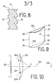
- FIG. 8 shows a Fresnel lens 80, with useful flanks 81 and 82, and a mask 83. If the Fresnel lens has symmetry of revolution, the mask can also have this same symmetry, and be composed of a set of opaque crowns, located in a plane perpendicular to the axis of the lens 80.
- Two useful flanks such as the flanks 41 and 42 of FIG. 4 behave like a prism.
- a first way to achieve this is to use the connecting flanks, giving them an angle of inclination such that there is total reflection of the light having penetrated into the material via a useful flank.
- FIG. 7 There is a Fresnel lens 70, useful flanks 71 and 74, connecting flanks 72 and 73.
- the sides 72 have a variable angle of inclination.
- the flank 73 has an angle of inclination such that the light entering said lens via the useful flank 74 undergoes on the flank 73 a total reflection. There will therefore be here a refraction on the flank 74, followed by a reflection inside the lens, on the flank 73.
- On the side on the observer side it is possible, in the same way, to have connecting flanks 75 causing total reflection inside the lens; before passing via the useful output flank 76.
- the combination of the two successive total reflections makes it possible to produce a deflection of the light, this deviation coming to combine with the deviations caused by the useful flanks of entry and exit.
- FIG. 9 there can be seen, in perspective view, a lens 90 (thick or Fresnel) of rectangular overall shape, with two vertical edges 91 and 92, and two horizontal edges 93 and 94.
- a bar 95a joining the two upper corners 96 and 97 of the lens 90.
- Another bar 95b can also be arranged between the lower corners 98 and 99 of the lens 90.
- the modification of the optical effect can be used to enlarge the image preferably in the horizontal direction, for example, or to correct certain deformations of the lens. virtual image produced by the lens.
- said lens can be made from a material which is flexible enough to allow said lens, at least locally, to have a curvature. This flexibility will wrap the lens around an axis, to reduce its bulk when not in use.
Abstract
Description
La présente invention concerne l'agrandissement des images, telles que celles produites par des appareils de télévision. On utilise a cet effet un système optique tel qu'un ensemble comprenant au moins une lentille épaisse ou son équivalent, qui permet d'obtenir, à partir d'un objet réel, une image agrandie, avec la possibilité, pour un observateur, de se déplacer dans une zone assez vaste tout en observant une image correcte, c'est-à-dire sans déformation gênante.The present invention relates to the enlargement of images, such as those produced by television apparatus. For this purpose, an optical system is used such as an assembly comprising at least one thick lens or its equivalent, which makes it possible to obtain, from a real object, an enlarged image, with the possibility, for an observer, of move in a fairly large area while observing a correct image, that is to say without annoying deformation.
Dans la présente description, on appellera "générateur d'image" tout système produisant une image, tel que tube cathodique, écran à cristaux liquides, écran à plasma, par thermoluminescence, générateur d'hologramme ou tout autre moyen produisant des images à 2 ou 3 dimensions.In the present description, the term “image generator” will mean any system producing an image, such as cathode ray tube, liquid crystal screen, plasma screen, by thermoluminescence, hologram generator or any other means producing images with 2 or 3 dimensions.
On appellera "image source" l'image produite par le générateur d'image ; par exemple, si le générateur d'image est un tube cathodique, l'image source est portée par l'écran dudit tube.The image produced by the image generator will be called "source image"; for example, if the image generator is a cathode ray tube, the source image is carried by the screen of said tube.
On appellera "axe" de l'image source la droite perpendiculaire à l'image source en son centre.The line perpendicular to the source image at its center will be called the "axis" of the source image.
Dans le cas où l'image source admet deux plans de symétrie distincts, on appellera "axe" de l'image source la droite intersection de ces deux plans, et on appellera "centre" de l'image source l'intersection de ladite image avec l'axe de ladite image.In the case where the source image admits two distinct planes of symmetry, the straight intersection of these two planes will be called "axis" of the source image, and the intersection of said image will be called "center" of the source image. with the axis of said image.
On appellera "observateur" toute personne observant l'image source agrandie par un système agrandisseur d'image.We will call "observer" any person observing the source image enlarged by an image enlarger system.
On appellera "lentille épaisse" une pièce de matière transparente, ayant globalement la forme d'un disque ou d'un rectangle, et limitée sur chacune de ses deux faces par une surface. Ladite lentille épaisse ne possède pas obligatoirement une symétrie de révolution, et ne possède pas obligatoirement de plan de symétrie.We will call "thick lens" a piece of transparent material, generally having the shape of a disc or a rectangle, and limited on each of its two faces by a surface. Said thick lens does not necessarily have a symmetry of revolution, and does not necessarily have a plane of symmetry.
Dans une coupe d'une lentille épaisse par un plan, on dira que, dans ledit plan, une courbe intersection dudit plan et d'une des faces de ladite lentille est "convexe" en un point V si, pour tout point W au voisinage du point V, le segment VW est entièrement compris dans la matière transparente constituant ladite lentille. On dira que ladite courbe est "strictement convexe" en V si V et W sont les seuls points communs entre ledit segment VW et la surface de ladite lentille.In a section of a thick lens by a plane, we will say that, in said plane, an intersection curve of said plane and one of the faces of said lens is "convex" at a point V if, for any point W in the vicinity from point V, the segment VW is entirely included in the transparent material constituting said lens. It will be said that said curve is "strictly convex" in V if V and W are the only points in common between said segment VW and the surface of said lens.
De même, on dira qu'une telle courbe est "concave" en V si ledit segment VW est entièrement compris (hormis ses extrémités) à l'extérieur de ladite matière transparente.Similarly, it will be said that such a curve is "concave" in V if said segment VW is fully understood (except for its ends) outside of said transparent material.
On appellera "lentille de Fresnel" une forme de réalisation d'une lentille épaisse, ladite forme de réalisation utilisant la technique des échelons sur au moins une partie de ladite lentille de Fresnel.An embodiment of a thick lens will be called a "Fresnel lens", said embodiment using the step technique on at least part of said Fresnel lens.
On appellera "axe" d'une lentille la droite perpendiculaire à ladite lentille en son centre.The straight line perpendicular to said lens at its center will be called the "axis" of a lens.
Dans le cas où une lentille admet deux plans de symétrie distincts, on ap pellera "axe" de ladite lentille la droite intersection de ces deux plans, et on appellera "centre" de ladite lentille l'intersection de ladite lentille avec l'axe de ladite lentille.In the case where a lens admits two distinct planes of symmetry, we will call "axis" of said lens the straight intersection of these two planes, and we will call "center" of said lens the intersection of said lens with the axis of said lens.
On appellera "partie optiquement utile" une partie d'une lentille épaisse ou de Fresnel par où entrent ou sortent des rayons lumineux participant à la réalisation de l'effet d'agrandissement de l'image source.We will call "optically useful part" a part of a thick or Fresnel lens through which light rays enter or leave participating in the achievement of the enlargement effect of the source image.
On appellera "surface de Fresnel" une des deux surfaces à échelons d'une lentille de Fresnel.One of the two stepped surfaces of a Fresnel lens will be called a "Fresnel surface".
On appellera "flanc utile", sur une surface de Fresnel, un flanc par où entrent ou sortent des rayons lumineux participant à la réalisation de l'effet d'agrandissement de l'image source.We will call "useful flank", on a Fresnel surface, a flank through which light rays enter or leave participating in the realization of the enlargement effect of the source image.
On appellera "flanc de liaison", sur une surface de Fresnel, un flanc par où entrent ou sortent des rayons lumineux ne participant pas à la réalisation de l'effet d'agrandissement de l'image source. Deux flancs utiles successifs sont reliés entre eux par zéro (cas où deux flancs utiles successifs ont un point commun), un ou plusieurs flancs de liaison.We will call "connecting flank", on a Fresnel surface, a flank through which light rays come in or out that do not participate in achieving the enlargement effect of the source image. Two successive useful flanks are connected together by zero (case where two successive useful flanks have a common point), one or more connecting flanks.
On appellera "lentille cylindrique" une lentille épaisse ou de Fresnel générée par une surface plane fermée se déplaçant selon un segment de droite.We will call "cylindrical lens" a thick or Fresnel lens generated by a closed plane surface moving along a line segment.
On appellera "diagonale" d'une image la distance entre les deux points de ladite image les plus éloignés l'un de l'autre. Dans le cas où l'image est rectangulaire, sa "diagonale" est la diagonale du rectangle.The distance between the two points of said image which are the most distant from each other will be called "diagonal" of an image. In the case where the image is rectangular, its "diagonal" is the diagonal of the rectangle.
On appellera "agrandissement effectif" le rapport entre la tangente de l'angle sous lequel un segment de droite d'une image virtuelle, produite par un système optique, est vu par un observateur, et la tangente de l'angle sous lequel le segment de droite de l'image source correspondante serait vu par le même observateur si ledit système optique était absent.We will call "effective enlargement" the ratio between the tangent of the angle at which a line segment of a virtual image, produced by an optical system, is seen by an observer, and the tangent of the angle at which the segment on the right of the corresponding source image would be seen by the same observer if said optical system was absent.
On appellera "zone d'observation" la zone où peut se trouver l'observateur pour observer une image correcte. Dans le cas où le système optique possède une symétrie de révolution, la zone d'observation est un cône ayant pour axe l'axe de la lentille, et pour sommet le centre de la face de la lentille côté observateur. On caractérisera la zone d'observation par 1"'ouverture" du système, qui est le demi-angle au sommet dudit cône.The area where the observer can be located to observe a correct image will be called "observation area". In the case where the optical system has a symmetry of revolution, the observation zone is a cone having the axis of the lens as its axis, and the center of the face of the lens on the observer side as its apex. The observation area will be characterized by the "opening" of the system, which is the half-angle at the top of said cone.
Il existe des systèmes optiques constituant un arrière-plan technologique. Leurs domaines techniques et les problèmes optiques à résoudre ne sont pas ceux de la présente invention. US-A-3 936 151 décrit un système optique comportant une lentille ayant une face convexe au centre et concave à la périphérie, réalisée selon une technique à échelons non circulaires, et une face plane. La source lumineuse est ponctuelle. GB-A-902 535 décrit une lentille produisant un faisceau de rayons parallèles a partir exclusivement d'une source lumineuse ponctuelle (foyer de la lentille). US-A-4 423 438 décrit un système de projection pour images de télévision, produisant une image réelle. On utilise une lentille de Schmidt pour corriger une aberration sphérique. Cette lentille possède une face plane. US-A-3 980 399 décrit un procédé de fabrication d'une lentille ayant un profil convexe au centre et concave à la périphérie sur les deux faces de la lentille.There are optical systems which constitute a technological background. Their technical fields and the optical problems to be solved are not those of the present invention. US-A-3,936,151 describes a optical system comprising a lens having a convex face in the center and concave at the periphery, produced according to a technique with non-circular steps, and a planar face. The light source is point-like. GB-A-902 535 describes a lens producing a beam of parallel rays exclusively from a point light source (focal point of the lens). US-A-4,423,438 describes a projection system for television images, producing a real image. We use a Schmidt lens to correct a spherical aberration. This lens has a flat face. US-A-3 980 399 describes a method of manufacturing a lens having a convex profile in the center and concave at the periphery on the two faces of the lens.
Des systèmes connus pour l'agrandissement d'images sont décrits dans FR-A-1 346 696, FR-A-1 379 018, FR-A-2 472 197 et dans US-A-3 418 426. Dans ces systèmes connus, on utilise une lentille de Fresnel pour produire une image virtuelle agrandie d'une image source qui peut être constituée par un écran de télévision. FR-A-2 472 197 décrit une lentille de Fresnel simulant une lentille épaisse de révolution, dont la face côté image source est concave dans la région centrale de ladite lentille épaisse, et convexe dans la région périphérique, et dont la face côté observateur est partout convexe.Known systems for enlarging images are described in FR-A-1 346 696, FR-A-1 379 018, FR-A-2 472 197 and in US-A-3 418 426. In these known systems , a Fresnel lens is used to produce an enlarged virtual image of a source image which may consist of a television screen. FR-A-2 472 197 describes a Fresnel lens simulating a thick lens of revolution, the side of the source image side of which is concave in the central region of the said thick lens, and convex in the peripheral region, and the side of which is on the observer side everywhere convex.
Les inconvénients des systèmes cités ci-dessus sont les suivants :
- - la zone d'observation est très réduite (sauf pour FR-A-2 472 197)
- - l'encombrement du système est important, notamment pour FR-A-2 472 197, où d'une part la lentille est à une distance de l'image source égale à la diagonale de ladite image source, et où, d'autre part, ladite lentille est elle-même de dimensions importantes.
- - the observation area is very small (except for FR-A-2 472 197)
- - the size of the system is significant, in particular for FR-A-2 472 197, where on the one hand the lens is at a distance from the source image equal to the diagonal of said source image, and where, on the other apart, said lens is itself of large dimensions.
En revanche, le système selon la présente invention présente les avantages suivants :
- - le système permet d'agrandir l'image source d'un agrandissement effectif de l'ordre de 2, sans déformation notable de l'image ;
- - la zone d'observation est au moins aussi large que celle du système de FR-A-2 472 197 ;
- - l'encombrement est nettement moins important que celui du système selon FR-A-2 472 197.
- - the system makes it possible to enlarge the source image with an effective enlargement of the order of 2, without noticeable distortion of the image;
- - the observation area is at least as wide as that of the FR-A-2 472 197 system;
- - the space requirement is significantly less than that of the system according to FR-A-2 472 197.
Selon la présente invention, le système optique pour l'agrandissement d'images comprend au moins une lentille épaisse ou son équivalent, disposée entre d'une part une image source composée d'une pluralité de points et possédant un axe, et d'autre part un observateur ; en outre, il existe un plan parallèle à l'axe de l'image source, et coupant ledit système de manière telle que l'intersection dudit plan et dudit système comprenne au moins une courbe convexe dans sa partie centrale (proche dudit axe) et concave dans sa partie périphérique (plus éloignée dudit axe) ; de plus, il existe un plan parallèle à l'axe de l'image source et coupant ledit système de manière telle que l'intersection dudit plan et dudit système comprenne au moins une courbe qui soit entièrement convexe, et qui soit strictement convexe sur au moins une partie de ladite courbe (c'est-à-dire que ladite courbe ne peut être rectiligne qu'en partie, et non sur sa totalité).According to the present invention, the optical system for enlarging images comprises at least one thick lens or its equivalent, arranged between on the one hand a source image composed of a plurality of points and having an axis, and on the other shares an observer; in addition, there is a plane parallel to the axis of the source image, and intersecting said system in such a way that the intersection of said plane and said system comprises at least one convex curve in its central part (close to said axis) and concave in its peripheral part (further from said axis); in addition, there is a plane parallel to the axis of the source image and intersecting said system in such a way that the intersection of said plane and said system comprises at least one curve which is entirely convex, and which is strictly convex on at minus part of said curve (that is to say that said curve can only be rectilinear in part, and not over its entirety).
Dans une variante de la présente invention, ladite courbe entièrement convexe est entièrement strictement convexe.In a variant of the present invention, said entirely convex curve is entirely strictly convex.
L'invention sera mieux comprise, et d'autres buts, avantages et caractéristiques de celle-ci apparaîtront plus clairement à la lecture de la description qui suit, donnée à titre non limitatif, de deux modes préférés de réalisation, et à laquelle sont jointes trois planches de dessins, sur lesquelles :
- La figure 1 est une vue en coupe du système selon la présente invention, dans lequel la partie optique est une lentille épaisse, qui peut être réalisée dans une substance telle que du polyméthacrylate de méthyle.
- La figure 2 est une vue en perspective du système selon la présente invention, dans lequel la partie optique est une paire de lentilles épaisses cylindriques.
- La figure 3 est une vue en perspective du système selon la présente invention, dans lequel la partie optique est une lentille de Fresnel, qui peut être réalisée dans une substance telle que du polyméthacrylate de méthyle.
- La figure 4 est une vue en coupe partielle de la lentille de la figure 3, ladite vue précisant des paramètres pour la définition quantitative d'une réalisation préférée de la présente invention.
- Les figures 5, 6 et 8 sont des vues en coupe partielle de lentilles de Fresnel selon la présente invention, illustrant des moyens permettant de diminuer les rayons parasites transmis par lesdites lentilles.
- La figure 7 est une vue en coupe partielle d'une lentille de Fresnel selon la présente invention, illustrant des moyens permettant de modifier les caractéristiques de déviation des rayons lumineux par ladite lentille.
- La figure 9 est une vue en perspective d'une lentille (épaisse ou de Fresnel) selon la présente invention, munie d'un dispositif permettant de déformer ladite lentille.
- La figure 10 est une vue en coupe permettant de préciser l'importance de la région convexe d'une des faces du système optique selon la présente invention.
- Figure 1 is a sectional view of the system according to the present invention, in which the optical part is a thick lens, which can be made of a substance such as polymethyl methacrylate.
- Figure 2 is a perspective view of the system according to the present invention, in which the optical part is a pair of thick cylindrical lenses.
- FIG. 3 is a perspective view of the system according to the present invention, in which the optical part is a Fresnel lens, which can be produced in a substance such as polymethyl methacrylate.
- Figure 4 is a partial sectional view of the lens of Figure 3, said view specifying parameters for the quantitative definition of a preferred embodiment of the present invention.
- Figures 5, 6 and 8 are partial sectional views of Fresnel lenses according to the present invention, illustrating means for reducing the stray rays transmitted by said lenses.
- Figure 7 is a partial sectional view of a Fresnel lens according to the present invention, illustrating means for modifying the deflection characteristics of the light rays by said lens.
- Figure 9 is a perspective view of a lens (thick or Fresnel) according to the present invention, provided with a device for deforming said lens.
- Figure 10 is a sectional view for clarifying the importance of the convex region of one of the faces of the optical system according to the present invention.
En figure 1, on voit un mode de réalisation de la présente invention, en coupe, vue de dessus. On distingue l'image source 10, une lentille épaisse 12 et l'observateur 13. Dans ledit mode de réalisation, on suppose que l'image source 10 possède un axe 11. Le plan de coupe est parallèle à l'axe 11. Dans le cas présent, il contient l'axe 11. Du côté de l'image source, la courbe intersection de la lentille épaisse et du plan de coupe est convexe dans la partie centrale 14, et concave dans la partie périphérique 15. Du côté de l'observateur, la courbe 16, intersection de ladite lentille et du plan de coupe, est partout convexe, et strictement convexe sur au moins une partie de ladite courbe. La lentille 12 n'a pas nécessairement de symétrie de révolution. On distingue également un point M situé sur la courbe 14, 15, côté image source, et un point N situé sur la courbe 16. Les points M et N sont situés dans le plan de coupe, et sont situés à une même distance u dudit axe. Dans une variante de la présente invention, la distance de M à N est une fonction décroissante de la distance u. Un cas particulier de ladite variante est celui ou la lentille 12 possède une symétrie de révolution par rapport à l'axe 11.In Figure 1, we see an embodiment of the present invention, in section, top view. We distinguishes the
En figure 2, on voit un autre mode de réalisation de la présente invention, représenté en perspective. On distingue une image source 20 et son axe 21, une première lentille épaisse cylindrique 22, de génératrice verticale, une deuxième lentille épaisse cylindrique 23, de génératrice horizontale, et un observateur 24. Les surfaces de base des cylindres possèdent les mêmes propriétés que la vue en coupe de la lentille 12 dans la figure 1. Une variante de cette réalisation à base de lentilles cylindriques est constituée de lentilles de nature cylindrique, mais dans lesquelles la forme de la surface de base varie légèrement en fonction du déplacement le long de la génératrice.In Figure 2, we see another embodiment of the present invention, shown in perspective. There is a
En figure 3, on distingue une image source 30 et son axe 31, une lentille de Fresnel 32 selon la présente invention, et l'observateur 33. Ici, la lentille 32 admet un axe qui est également l'axe 31 de l'image source. Dans une variante, la lentille 32 pourrait n'admettre qu'un plan de symétrie vertical contenant l'axe 31 de l'image source. Dans une autre variante, la lentille 32 pourrait avoir un axe distinct de l'axe de l'image source, mais de préférence parallèle à ce dernier.In FIG. 3, a
La figure 4 est une vue en coupe partielle de la lentille 32 de la figure 3, coupe selon un plan vertical contenant l'axe 31. On distingue : la lentille de Fresnel 40 et son axe 43 ; un flanc actif 41 et un flanc de liaison 44, situés côté source un flanc actif 42 et un flanc de liaison 45, situés côté observateur ; les extrémités F et J du flanc 41, F étant plus éloigné de l'axe 43 que J ; les extrémités H et K du flanc 42, H étant plus éloigné de l'axe 43 que K ; l'extrémité G du flanc 44, G étant plus proche de l'axe 43 que J ; l'extrémité 1 du flanc 45, 1 étant plus proche de l'axe 43 que J ; un repère Oxz, 0 étant au-dessus de l'axe 43, Oz étant parallèle à l'axe 43 et pointant vers l'observateur, Ox étant perpendiculaire à l'axe 43 et pointant vers l'axe 43. Dans ces conditions, on définira le flanc FJ par l'angle orienté![]()
![]()
![]()
![]()
De la même façon, on appellera b et d les angles définissant des flancs de liaison tels que 44 et 45. On aura :![]()
![]()
![]()
![]()
![]()
![]()
1"'angle d'inclinaison" du flanc. Dans la figure 4, on voit par exemple que les angles a et c définissant les flancs FJ et HK sont positifs et inférieurs à 7(/2 radian, alors que les angles b et d sont négatifs et supérieurs à -7(/2 radian. Pour définir un flanc tel que FJ, on introduit également la distance entre le milieu de ce flanc (milieu pris dans le plan de coupe, c'est-à-dire dans le plan de la figure 4) et l'axe 43 ; on appellera cette distance la "distance du flanc à l'axe".1 "'tilt angle" of the sidewall. In Figure 4, we see for example that the angles a and c defining the flanks FJ and HK are positive and less than 7 (/ 2 radian, while the angles b and d are negative and greater than - 7 (/ 2 radian To define a flank such as FJ, we also introduce the distance between the middle of this flank (middle taken in the section plane, that is to say in the plane of FIG. 4) and the
Si, en un point tel que F ou J, l'angle formé par les deux flancs contigus, mesuré à l'intérieur de la matière de la lentille, est inférieur à 11' radians en valeur absolue, on dira que ledit point est une "crête" ; dans le cas où ledit angle a une valeur absolue supérieure à radians, on dira que ledit point est un "val". En figure 4, on voit que F est une crête, alors que J est un val.If, at a point such as F or J, the angle formed by the two contiguous flanks, measured inside the material of the lens, is less than 11 'radians in absolute value, it will be said that said point is a "Crete" ; in the case where said angle has an absolute value greater than radians, it will be said that said point is a "val". In Figure 4, we see that F is a peak, while J is a val.
On appellera "sillon" l'ensemble constitué par deux flancs contigus tels que FJ et JG, se joignant en un val. On appellera "largeur" d'un sillon la distance entre deux crêtes successives telles que F et G. Les sillons ont généralement une largeur constante sur une face d'une lentille de Fresnel. Mais on pourra aussi prévoir des sillons de largeur variable.We will call "groove" the set consisting of two contiguous flanks such as FJ and JG, joining in a valley. The distance between two successive crests such as F and G will be called the "width" of a groove. The grooves generally have a constant width on one face of a Fresnel lens. However, it is also possible to provide grooves of variable width.
On appellera "rayon d'inflexion", dans un plan de coupe tel que celui de la figure 4, la distance entre l'axe et le premier flanc utile (en partant de l'axe 43) pour lequel la fonction donnant l'angle d'inclinaison en fonction de la distance du flanc à l'axe change de sens de variation, ledit premier flanc n'étant pas celui situé sur l'axe 43.We will call "inflection radius", in a cutting plane such as that of FIG. 4, the distance between the axis and the first useful flank (starting from axis 43) for which the function giving the angle of inclination as a function of the distance from the flank to the axis changes direction of variation, said first flank not being that located on
On appellera "rayon de platitude", dans un plan de coupe tel que celui de la figure 4, la distance entre l'axe et le premier flanc utile (en partant de l'axe 43) ayant un angle d'inclinaison nul, ledit flanc n'étant pas celui situé sur l'axe 43. En général, le rayon de platitude n'est pas égal au rayon d'inflexion.We will call "radius of flatness", in a cutting plane such as that of FIG. 4, the distance between the axis and the first useful flank (starting from axis 43) having a zero angle of inclination, said flank not being that located on
La lentille de Fresnel 32 est une réalisation selon une technique à échelons de la lentille épaisse 12. Les deux faces sont entièrement réalisées en technique à échelons. Cependant, on pourrait ne réaliser. selon ladite technique à échelons, qu'une des deux faces, qu'une partie de chacune des deux faces, ou qu'une partie d'une seule face. Pour la lentille 32, les fonctions représentant les angles d'inclinaison des flancs utiles 41 et 42 en fonction de la distance desdits flancs à l'axe 43 de la lentille 32 ont les caractéristiques suivantes :
- - pour les flancs utiles de la face côté image source, la fonction est décroissante jusqu'à une distance de l'ordre du rayon d'inflexion, puis croissante ;
- - pour les flancs utiles de la face côté observateur, la fonction est croissante.
- - for the useful sides of the face on the source image side, the function is decreasing up to a distance of the order of the inflection radius, then increasing;
- - for the useful sides of the face on the observer side, the function is increasing.
Dans le cas où une partie seulement d'une face est réalisée en technique à échelons, les caractéristiques de décroissance et de croissance indiquées ci-dessus ne concernent que ladite partie. Dans le cas où une face ne comporte aucune partie réalisée en technique à échelons, lesdites caractéristiques ne concernent pas ladite face. Ainsi, on aura, de manière générale :
- - pour la partie réalisée en technique de Fresnel sur la face côté image source, la fonction représentant les flancs utiles est d'abord décroissante, puis croissante ;
- - pour la partie réalisée en technique de Fresnel sur la face côté observateur, la fonction représentant les flancs utiles est croissante.
- - for the part produced in Fresnel technique on the source image side, the function representing the useful sides is first decreasing, then increasing;
- - for the part produced in Fresnel technique on the side on the observer side, the function representing the useful sides is increasing.
En outre, dans la présente invention, les fonctions donnant les angles d'inclinaison des flancs utiles 41 et 42 en fonction de la distance desdits flancs à l'axe 43 de la lentille de Fresnel sont telles que, en tout point de ladite lentille, la fonction donnant l'angle d'inclinaison du flanc utile 42 côté observateur a une valeur supérieure à celle de la fonction donnant l'angle d'inclinaison du flanc utile 41 côté image source.Furthermore, in the present invention, the functions giving the angles of inclination of the
Une manière de réduire les rayons parasites passant à travers les flancs de liaison est de faire en sorte que les fonctions donnant les angles d'inclinaison des flancs de liaison en fonction de la distance desdits flancs au centre de la lentille de Fresnel aient les caractéristiques suivantes :
- - pour les flancs de liaison de la face côté image source, la fonction devra être décroissante jusqu'à une distance de l'ordre du rayon d'inflexion, puis croissante, avec une discontinuité pour x = rayon de platitude ;
- - pour les flancs de liaison de la face côté observateur, la fonction devra être croissante jusqu'à une distance de l'ordre du rayon d'inflexion, puis décroissante jusqu'à une distance de l'ordre de trois fois le rayon d'inflexion, puis croissante.
- - for the connecting flanks of the face on the source image side, the function must be decreasing up to a distance of the order of the radius of inflection, then increasing, with a discontinuity for x = radius of flatness;
- - for the connecting flanks of the face on the observer side, the function must be increasing up to a distance of the order of the inflection radius, then decreasing up to a distance of the order of three times the radius of inflection, then increasing.
Dans un premier mode de réalisation préféré de la présente invention, des tests ont montré que l'on a :
- k l'agrandissement effectif du système,
- a l'ouverture du système en degrés,
- r le rayon d'inflexion en mètres,
- D la diagonale de l'image source en mètres.
- E varie de 0,3 D à 1,5 D ; k varie de 1,7 à 2,7 ; a varie de 14. à 36°.
- k the effective enlargement of the system,
- at the opening of the system in degrees,
- r the inflection radius in meters,
- D the diagonal of the source image in meters.
- E varies from 0.3 D to 1.5 D; k varies from 1.7 to 2.7; a varies from 14 . at 36 °.
Dans un deuxième mode de réalisation préféré de la présente invention, des tests ont montré que, pour une image source de 70 cm de diagonale, avec une lentille constituée d'une matière dont l'indice de réfraction est 1,49, mesurant 80 cm de haut et 1,60 m de large, située à 30 cm de l'image source, et présentant des sillons ayant une largeur de 1 mm et possédant la symétrie de révolution, les angles d'inclinaison des sillons sont selon les formules polynomiales suivantes (on note Rp la valeur de x comprise entre 0,3 et 0,4 et telle que a(Rp) = 0 ; on a approximativement : Rp = 0,32 ; Rp est le rayon de platitude) :
- - face côté image source, flancs utiles

- - face côté image source, flancs de liaison :


- - face côté observateur, flancs utiles :

- - face côté observateur, flancs de liaison :

- - face on source image side, useful sides
- - face on source image side, connecting sides:
- - observer side, useful sides:
- - observer side, connecting sides:
L'homme de l'art pourra adapter ces formules pour des matières dont l'indice de réfraction est différent de 1,49.Those skilled in the art can adapt these formulas for materials whose refractive index is different from 1.49.
Sur chaque face de la lentille 40, les flancs utiles et les flancs de liaison alternent. Au centre de la lentille 40, on commence par un flanc utile 46 côté image source, et un flanc utile 47 côté observateur.On each face of the
Par les flancs de liaison passe de la lumière parasite. On peut, pour réduire les effets de cette lumière, calculer les flancs de liaison au mieux. On peut également opacifier des flancs de liaison, comme indiqué en figure 5. On y distingue une lentille de Fresnel 50 avec des flancs utiles 51 et 52, et avec des flancs de liaison 53 et 54. On peut opacifier les flancs de liaison sur les deux faces ou sur une seule face, ou sur certaines régions d'au moins une des deux faces. L'opacification des flancs de la figure 5 pourra se faire par dépôt, par sérigraphie, projection ou par procédé cathodique.Stray light passes through the connecting flanks. We can, to reduce the effects of this light, calculate the connecting flanks at best. One can also opacify connecting flanks, as indicated in FIG. 5. There is a
La figure 6 montre une disposition différente des flancs. On y distingue une lentille de Fresnel 60, des flancs utiles 61 et 64, des flancs de liaison 62 et 63. Ici, il y a deux flancs de liaison, et non plus un seul, entre deux flancs utiles successifs. Le flanc 62 a un angle d'inclinaison variable. Le flanc 63 a un angle d'inclinaison nul. Ceci permet d'opacifier aisément les flancs tels que le flanc 63, à l'aide d'un simple marquage sérigraphique, par exemple.Figure 6 shows a different arrangement of the sides. There is a
Une autre façon de réduire les effets des rayons lumineux parasites est de disposer, entre les faces de la lentille de Fresnel, un masque opaque à certains endroits seulement. Ainsi, la figure 8 montre une lentille de Fresnel 80, avec des flancs utiles 81 et 82, et un masque 83. Si la lentille de Fresnel a la symétrie de révolution, le masque pourra également avoir cette même symétrie, et être composé d'un ensemble de couronnes opaques, situées dans un plan perpendiculaire à l'axe de la lentille 80.Another way to reduce the effects of stray light rays is to have an opaque mask between the faces of the Fresnel lens only in certain places. Thus, FIG. 8 shows a
On peut également chercher à modifier la façon dont deux flancs utiles dévient la lumière. Deux flancs utiles tels que les flancs 41 et 42 de la figure 4 se comportent comme un prisme. On peut ajouter à cet effet de déviation de la lumière un effet de réflexion en utilisant le phénomène de la réflexion totale. Un premier moyen pour y parvenir est d'utiliser les flancs de liaison, en leur donnant un angle d'inclinaison tel qu'il y ait réflexion totale de la lumière ayant pénétré dans la matière via un flanc utile. Un autre moyen d'y parvenir est représenté en figure 7. On y distingue une lentille de Fresnel 70, des flancs utiles 71 et 74, des flancs de liaison 72 et 73. Ici, comme en figure 6, il y a deux flancs de liaison, et non plus un seul, entre deux flancs utiles successifs. Les flanc 72 a un angle d'inclinaison variable. Le flanc 73 a un angle d'inclinaison tel que la lumière pénétrant dans ladite lentille via le flanc utile 74 subisse sur le flanc 73 une réflexion totale. On aura donc ici une réfraction sur le flanc 74, suivie d'une réflexion à l'intérieur de la lentille, sur le flanc 73. Sur la face côté observateur, on peut, de la même façon, disposer des flancs de liaison 75 provoquant une réflexion totale à l'intérieur de la lentille; avant passage via le flanc utile de sortie 76. La combinaison des deux réflexions totales successives permet de réaliser une déviation de la lumière, cette déviation venant se combiner avec les déviations provoquées par les flancs utiles d'entrée et de sortie.We can also seek to modify the way in which two useful sides deflect the light. Two useful flanks such as the
On peut également obtenir une réflexion sur un flanc de liaison en déposant sur ledit flanc une couche d'un produit réfléchissant la lumière. On peut, en outre, associer sur un même flanc, un produit réfléchissant et un produit opacifiant.It is also possible to obtain a reflection on a connecting flank by depositing on said flank a layer of a light-reflecting product. It is also possible to combine a reflective product and an opacifying product on the same flank.
En figure 9, on distingue, vue en perspective, une lentille 90 (épaisse ou de Fresnel) de forme globale rectangulaire, avec deux bords verticaux 91 et 92, et deux bords horizontaux 93 et 94. On distingue en outre une barre 95a, joignant les deux coins supérieurs 96 et 97 de la lentille 90. En faisant varier la longueur de la barre 95a, on déforme la lentille 90, modifiant ainsi une courbure de ladite lentille, et modifiant, par suite, l'effet optique produit par ladite lentille. On peut disposer également une autre barre 95b entre les coins inférieurs 98 et 99 de la lentille 90. La modification de l'effet optique peut servir à agrandir l'image préférentiellement dans le sens horizontal, par exemple, ou à corriger certaines déformations de l'image virtuelle produite par la lentille. On pourra utiliser, à la place des barres de la figure 9, des résistances chauffantes et des alliages à mémoire de forme.In FIG. 9, there can be seen, in perspective view, a lens 90 (thick or Fresnel) of rectangular overall shape, with two
En figure 10 sont représentés schématiquement, vus en coupe, une image source 100 et son axe 101, un point P de l'axe 101, et une lentille 102 selon la présente invention, placée entre l'image source 100 et le point P. On distingue également un observateur 105. Le point P est situé entre l'observateur 105 et l'image source. Le plan de coupe est, selon la présente invention (voir la description de la figure 1), parallèle à l'axe de l'image source et tel que, du côté de l'image source 100, la face de la lentille 102 a avec le plan de coupe une intersection qui est une courbe dont une région centrale 104 est convexe et dont une région périphérique 103a et 103b est concave. On distingue également en figure 10 un segment de droite ST, situé dans le plan de coupe de la figure 10 ; ledit segment de droite est perpendiculaire à l'axe 101 de l'image source 100 ; ledit segment de droite a pour centre le centre de l'image source 100, et pour longueur la diagonale de l'image source 100. En figure 10 sont également représentés les points Q et R qui constituent la frontière entre la région centrale 104 et la région périphérique 103. L'angle sous lequel P voit ladite région centrale est l'angle (PQ, PR). On appellera β la moitié de cet angle. L'angle sous lequel P voit le segment ST est l'angle (PS, PT). On appellera r la moitié de cet angle. Dans le cas d'une lentille épaisse telle que la lentille 102, on appellera "rayon d'inflexion" la moitié de la longueur QR. Soit z la distance de P à ladite image source. On définit la position du point P par :
- z = [(0,0164 k-0,0298) a2 + (1,206-0,7 k) α + 7,334 k-11,042]


- z = [(0.0164 k-0.0298) a2 + (1.206-0.7 k) α + 7.334 k-11.042]
On remarque que ladite tangente ne dépend pas de la distance entre l'image source et la lentille, pour un k et un α donnés. La tangente de l'angle r vaut :![]()
![]()
![]()
![]()
Par exemple, si k=2 et si α=26°, la distance z de P à ladite image source est égale à 0,93 fois la diagonale de ladite image source, et β est de l'ordre de 44,7°, d'après la formule (1) ci-dessus sa tangente est de 0,991. Par ailleurs, r vaut 28,3* ; sa tangente est de 0,538. On a en outre : (0,6 k-0,555)/0,35 = 1,84.For example, if k = 2 and if α = 26 °, the distance z from P to said source image is equal to 0.93 times the diagonal of said source image, and β is of the order of 44.7 °, according to formula (1) above its tangent is 0.991. In addition, r is worth 28.3 * ; its tangent is 0.538. We also have: (0.6 k-0.555) / 0.35 = 1.84.
Dans une variante d'une lentille selon la présente invention, on pourra utiliser une matière transparente traitée de manière à ce que le facteur de transmission de la lumière par ladite lentille diminue en présence d'un rayonnement d'une intensité sensiblement supérieure à l'intensité maximale du rayonnement de l'image source. Ceci permet d'atténuer d'éventuels éblouissements ou contrastes trop violents dans le cas où une lumière importante atteint la lentille. On pourra prévoir des moyens tels que ceux utilisés dans les lunettes solaires à opacité variable, ou utiliser des systèmes à cristaux liquides.In a variant of a lens according to the present invention, it is possible to use a transparent material treated so that the light transmittance factor by said lens decreases in the presence of radiation of an intensity substantially greater than the maximum radiation intensity of the source image. This makes it possible to attenuate possible dazzling or too violent contrasts in the event that a significant light reaches the lens. We can provide means such as those used in sunglasses with variable opacity, or use liquid crystal systems.
Enfin, dans une variante d'une lentille selon la présente invention, on pourra fabriquer ladite lentille dans une matière suffisamment souple pour permettre de donner à ladite lentille, au moins localement, une courbure. Cette souplesse permettra d'enrouler la lentille autour d'un axe, afin de diminuer son encombrement lorsqu'elle n'est pas utilisée.Finally, in a variant of a lens according to the present invention, said lens can be made from a material which is flexible enough to allow said lens, at least locally, to have a curvature. This flexibility will wrap the lens around an axis, to reduce its bulk when not in use.
Bien évidemment, l'homme de métier pourra apporter de nombreuses modifications à la présente invention, sans sortir du cadre des revendications.Obviously, a person skilled in the art can make numerous modifications to the present invention, without going beyond the ambit of the claims.
Claims (13)
Applications Claiming Priority (3)
| Application Number | Priority Date | Filing Date | Title |
|---|---|---|---|
| FR8909371A FR2649799B1 (en) | 1989-07-12 | 1989-07-12 | OPTICAL SYSTEM FOR MAGNIFYING IMAGES |
| FR8909371 | 1989-07-12 | ||
| US07/551,529 US5583702A (en) | 1989-07-12 | 1990-07-11 | Optical system for enlarging images |
Publications (2)
| Publication Number | Publication Date |
|---|---|
| EP0408445A1 true EP0408445A1 (en) | 1991-01-16 |
| EP0408445B1 EP0408445B1 (en) | 1996-02-28 |
Family
ID=26227468
Family Applications (1)
| Application Number | Title | Priority Date | Filing Date |
|---|---|---|---|
| EP90401990A Expired - Lifetime EP0408445B1 (en) | 1989-07-12 | 1990-07-10 | Optical device for image magnification |
Country Status (6)
| Country | Link |
|---|---|
| US (1) | US5583702A (en) |
| EP (1) | EP0408445B1 (en) |
| JP (1) | JPH03136016A (en) |
| CA (1) | CA2020819A1 (en) |
| DE (1) | DE69025502T2 (en) |
| FR (1) | FR2649799B1 (en) |
Cited By (1)
| Publication number | Priority date | Publication date | Assignee | Title |
|---|---|---|---|---|
| GB2274727A (en) * | 1993-01-29 | 1994-08-03 | Virtuality Entertainment Ltd | Optical display system |
Families Citing this family (29)
| Publication number | Priority date | Publication date | Assignee | Title |
|---|---|---|---|---|
| DE4228962C2 (en) * | 1991-08-30 | 1996-08-14 | Kansei Kk | Optical system for enlarging a display field |
| US6057537A (en) * | 1997-09-29 | 2000-05-02 | Eastman Kodak Company | Optical scanner feedback system having a reflected cylinder lens |
| US5932151A (en) * | 1997-09-29 | 1999-08-03 | Imation Corp. | Method of making a flexible lens |
| US6002524A (en) * | 1997-09-29 | 1999-12-14 | Imation Corp. | Flexible lens |
| US6108025A (en) * | 1997-09-29 | 2000-08-22 | Eastman Kodak Company | Optical scanner system having a laser beam power attentuation mechanism |
| US6094287A (en) * | 1998-12-03 | 2000-07-25 | Eastman Kodak Company | Wobble correcting monogon scanner for a laser imaging system |
| DE19932592A1 (en) * | 1999-07-13 | 2001-01-18 | Lissotschenko Vitalij | Imaging system |
| US20050095407A1 (en) * | 2003-11-04 | 2005-05-05 | Coburn Joseph W.Jr. | Spaced-apart fresnel lens decorative material and process of manufacturing the material |
| JP4365435B2 (en) * | 2007-10-12 | 2009-11-18 | リアルヴュー イノべイションズ リミテッド | Depth enhancement screen |
| TWI357481B (en) * | 2008-12-05 | 2012-02-01 | Ind Tech Res Inst | A light source module for producing polarized ligh |
| DE102009049167A1 (en) * | 2009-10-12 | 2011-05-05 | Imos Gubela Gmbh | Safety magnifying glass for magnifying and avoiding burning glass effects, has optical system for focusing of incident light with two light transmitting surfaces |
| US20110299168A1 (en) * | 2010-06-04 | 2011-12-08 | Combs Jeffrey S | Display Screen Covers Having Personalized Refractive Power Capabilities |
| US9778829B2 (en) | 2012-02-17 | 2017-10-03 | Lenovo (Singapore) Pte. Ltd. | Magnification based on eye input |
| US9110635B2 (en) | 2013-12-03 | 2015-08-18 | Lenova (Singapore) Pte. Ltd. | Initiating personal assistant application based on eye tracking and gestures |
| US10163455B2 (en) | 2013-12-03 | 2018-12-25 | Lenovo (Singapore) Pte. Ltd. | Detecting pause in audible input to device |
| US9213659B2 (en) | 2013-12-03 | 2015-12-15 | Lenovo (Singapore) Pte. Ltd. | Devices and methods to receive input at a first device and present output in response on a second device different from the first device |
| US9709708B2 (en) | 2013-12-09 | 2017-07-18 | Lenovo (Singapore) Pte. Ltd. | Adjustable display optics |
| US10180716B2 (en) | 2013-12-20 | 2019-01-15 | Lenovo (Singapore) Pte Ltd | Providing last known browsing location cue using movement-oriented biometric data |
| US9633252B2 (en) | 2013-12-20 | 2017-04-25 | Lenovo (Singapore) Pte. Ltd. | Real-time detection of user intention based on kinematics analysis of movement-oriented biometric data |
| US10073671B2 (en) | 2014-01-20 | 2018-09-11 | Lenovo (Singapore) Pte. Ltd. | Detecting noise or object interruption in audio video viewing and altering presentation based thereon |
| US9811095B2 (en) | 2014-08-06 | 2017-11-07 | Lenovo (Singapore) Pte. Ltd. | Glasses with fluid-fillable membrane for adjusting focal length of one or more lenses of the glasses |
| US9535497B2 (en) | 2014-11-20 | 2017-01-03 | Lenovo (Singapore) Pte. Ltd. | Presentation of data on an at least partially transparent display based on user focus |
| US10860094B2 (en) | 2015-03-10 | 2020-12-08 | Lenovo (Singapore) Pte. Ltd. | Execution of function based on location of display at which a user is looking and manipulation of an input device |
| US10013540B2 (en) | 2015-03-10 | 2018-07-03 | Lenovo (Singapore) Pte. Ltd. | Authentication based on body movement |
| US10499164B2 (en) | 2015-03-18 | 2019-12-03 | Lenovo (Singapore) Pte. Ltd. | Presentation of audio based on source |
| US10621431B2 (en) | 2015-03-27 | 2020-04-14 | Lenovo (Singapore) Pte. Ltd. | Camera that uses light from plural light sources disposed on a device |
| US20190094520A1 (en) * | 2017-03-24 | 2019-03-28 | Carrill D. Kelly | Vision correction device for a display |
| CN109901252B (en) * | 2017-12-07 | 2020-04-14 | 京东方科技集团股份有限公司 | Optical lens, glasses and display device |
| US10955988B1 (en) | 2020-02-14 | 2021-03-23 | Lenovo (Singapore) Pte. Ltd. | Execution of function based on user looking at one area of display while touching another area of display |
Citations (7)
| Publication number | Priority date | Publication date | Assignee | Title |
|---|---|---|---|---|
| GB902535A (en) * | 1959-04-06 | 1962-08-01 | James A Jobling And Company Lt | Improvements in or relating to lenses |
| US3447860A (en) * | 1967-07-03 | 1969-06-03 | James W Lucas | Large aperture achromat objective |
| DE2210727A1 (en) * | 1971-03-05 | 1972-09-14 | Hitachi Ltd | Correction lens for use in the manufacture of a fluorescent coating on a color television picture tube |
| US3936151A (en) * | 1972-12-04 | 1976-02-03 | Hitachi, Ltd. | Correction lenses utilized to form fluorescent screens of colour picture tubes |
| US3980399A (en) * | 1971-11-25 | 1976-09-14 | U.S. Philips Corporation | Aspheric optical elements |
| FR2472197A1 (en) * | 1979-12-18 | 1981-06-26 | Cintra Daniel | Fresnel lens for TV screen - has grooves with sidewall being functions of groove and lens radii |
| US4423438A (en) * | 1981-02-26 | 1983-12-27 | Nec Kansai, Ltd. | Projection type cathode ray tube with masking means |
Family Cites Families (4)
| Publication number | Priority date | Publication date | Assignee | Title |
|---|---|---|---|---|
| US2683394A (en) * | 1951-09-08 | 1954-07-13 | American Optical Corp | Wide aperture optical projection lens system |
| FR1346696A (en) * | 1963-02-06 | 1963-12-20 | auxiliary screen for television set | |
| FR1379018A (en) * | 1963-10-08 | 1964-11-20 | Holder for TV picture magnifier | |
| US3523721A (en) * | 1968-12-09 | 1970-08-11 | Zeiss Jena Veb Carl | Spherically corrected fresnel lenses and mirrors with partial field correction |
-
1989
- 1989-07-12 FR FR8909371A patent/FR2649799B1/en not_active Expired - Fee Related
-
1990
- 1990-07-10 EP EP90401990A patent/EP0408445B1/en not_active Expired - Lifetime
- 1990-07-10 CA CA002020819A patent/CA2020819A1/en not_active Abandoned
- 1990-07-10 DE DE69025502T patent/DE69025502T2/en not_active Expired - Fee Related
- 1990-07-11 US US07/551,529 patent/US5583702A/en not_active Expired - Fee Related
- 1990-07-12 JP JP2182849A patent/JPH03136016A/en active Pending
Patent Citations (7)
| Publication number | Priority date | Publication date | Assignee | Title |
|---|---|---|---|---|
| GB902535A (en) * | 1959-04-06 | 1962-08-01 | James A Jobling And Company Lt | Improvements in or relating to lenses |
| US3447860A (en) * | 1967-07-03 | 1969-06-03 | James W Lucas | Large aperture achromat objective |
| DE2210727A1 (en) * | 1971-03-05 | 1972-09-14 | Hitachi Ltd | Correction lens for use in the manufacture of a fluorescent coating on a color television picture tube |
| US3980399A (en) * | 1971-11-25 | 1976-09-14 | U.S. Philips Corporation | Aspheric optical elements |
| US3936151A (en) * | 1972-12-04 | 1976-02-03 | Hitachi, Ltd. | Correction lenses utilized to form fluorescent screens of colour picture tubes |
| FR2472197A1 (en) * | 1979-12-18 | 1981-06-26 | Cintra Daniel | Fresnel lens for TV screen - has grooves with sidewall being functions of groove and lens radii |
| US4423438A (en) * | 1981-02-26 | 1983-12-27 | Nec Kansai, Ltd. | Projection type cathode ray tube with masking means |
Cited By (2)
| Publication number | Priority date | Publication date | Assignee | Title |
|---|---|---|---|---|
| GB2274727A (en) * | 1993-01-29 | 1994-08-03 | Virtuality Entertainment Ltd | Optical display system |
| GB2274727B (en) * | 1993-01-29 | 1996-06-12 | Virtuality Entertainment Ltd | Optical system |
Also Published As
| Publication number | Publication date |
|---|---|
| DE69025502T2 (en) | 1996-10-31 |
| CA2020819A1 (en) | 1991-01-13 |
| DE69025502D1 (en) | 1996-04-04 |
| JPH03136016A (en) | 1991-06-10 |
| FR2649799B1 (en) | 1993-05-28 |
| US5583702A (en) | 1996-12-10 |
| FR2649799A1 (en) | 1991-01-18 |
| EP0408445B1 (en) | 1996-02-28 |
Similar Documents
| Publication | Publication Date | Title |
|---|---|---|
| EP0408445B1 (en) | Optical device for image magnification | |
| JP2916063B2 (en) | Tapered multilayer lighting device | |
| EP2277074B1 (en) | Informative eyeglasses | |
| DE69728754T2 (en) | REAR LIGHTING DEVICE OF A LIQUID CRYSTAL DISPLAY DEVICE | |
| EP0487385B1 (en) | Collimated display system with off-axis spherical mirror for simulator | |
| FR2632086A1 (en) | DISPLAY APPARATUS AND METHOD | |
| EP0880724A1 (en) | Display device and flat television screen using this device | |
| FR2925171A1 (en) | OPTICAL GUIDE AND OPTICAL SYSTEM OF EYE VISION | |
| WO2018138223A1 (en) | Optical detector of particles | |
| FR2627292A1 (en) | PARTIAL ZONE DIAPHRAGM OPTICAL SYSTEM | |
| EP0121962B1 (en) | Apparatus for optically coupling light guides | |
| EP3583402B1 (en) | Optical particle detector and method of manufacturing an optical particle detector | |
| FR2634907A1 (en) | MULTISPECTRAL MIRROR OPTICAL DEVICE | |
| EP4067950A1 (en) | Optical guide and corresponding manufacturing method | |
| EP0738077B1 (en) | Compact video monitor or TV of the rear-screen type | |
| FR2925172A1 (en) | Optical light beam guiding device for informative spectacles, has extraction section including microstructure provided with plane surface that causes output of reflected light rays of light beam affecting plane surface, from guide | |
| EP0459850A1 (en) | Head-up display and helmet comprising at least one such display | |
| FR3011125A1 (en) | CATADIOPTRIC DEVICE ENHANCING THE VISUALIZATION OF AN IMAGE PLACED IN FRONT OF A SOLAR SENSOR | |
| WO2021083787A1 (en) | Diffractive optical element comprising a metasurface for tirf microscopy | |
| WO2024002600A1 (en) | Optical device for scanning a light beam over a part to be machined | |
| FR2472197A1 (en) | Fresnel lens for TV screen - has grooves with sidewall being functions of groove and lens radii | |
| CN212569191U (en) | Transmission type volume holographic grating | |
| CA2999799A1 (en) | Optical system for thermal imager | |
| EP0553583A1 (en) | Infrared camera with auto-athermalised optical system | |
| JP2002277963A (en) | Back projection screen |
Legal Events
| Date | Code | Title | Description |
|---|---|---|---|
| PUAI | Public reference made under article 153(3) epc to a published international application that has entered the european phase |
Free format text: ORIGINAL CODE: 0009012 |
|
| AK | Designated contracting states |
Kind code of ref document: A1 Designated state(s): BE CH DE ES FR GB IT LI NL SE |
|
| 17P | Request for examination filed |
Effective date: 19910710 |
|
| 17Q | First examination report despatched |
Effective date: 19930721 |
|
| GRAA | (expected) grant |
Free format text: ORIGINAL CODE: 0009210 |
|
| AK | Designated contracting states |
Kind code of ref document: B1 Designated state(s): BE CH DE ES FR GB IT LI NL SE |
|
| PG25 | Lapsed in a contracting state [announced via postgrant information from national office to epo] |
Ref country code: IT Free format text: LAPSE BECAUSE OF FAILURE TO SUBMIT A TRANSLATION OF THE DESCRIPTION OR TO PAY THE FEE WITHIN THE PRE;WARNING: LAPSES OF ITALIAN PATENTS WITH EFFECTIVE DATE BEFORE 2007 MAY HAVE OCCURRED AT ANY TIME BEFORE 2007. THE CORRECT EFFECTIVE DATE MAY BE DIFFERENT FROM THE ONE RECORDED.SCRIBED TIME-LIMIT Effective date: 19960228 Ref country code: NL Free format text: LAPSE BECAUSE OF FAILURE TO SUBMIT A TRANSLATION OF THE DESCRIPTION OR TO PAY THE FEE WITHIN THE PRESCRIBED TIME-LIMIT Effective date: 19960228 Ref country code: ES Free format text: THE PATENT HAS BEEN ANNULLED BY A DECISION OF A NATIONAL AUTHORITY Effective date: 19960228 |
|
| REF | Corresponds to: |
Ref document number: 69025502 Country of ref document: DE Date of ref document: 19960404 |
|
| PG25 | Lapsed in a contracting state [announced via postgrant information from national office to epo] |
Ref country code: SE Effective date: 19960531 |
|
| GBT | Gb: translation of ep patent filed (gb section 77(6)(a)/1977) |
Effective date: 19960530 |
|
| PG25 | Lapsed in a contracting state [announced via postgrant information from national office to epo] |
Ref country code: CH Effective date: 19960731 Ref country code: BE Effective date: 19960731 Ref country code: LI Effective date: 19960731 |
|
| NLV1 | Nl: lapsed or annulled due to failure to fulfill the requirements of art. 29p and 29m of the patents act | ||
| PLBE | No opposition filed within time limit |
Free format text: ORIGINAL CODE: 0009261 |
|
| STAA | Information on the status of an ep patent application or granted ep patent |
Free format text: STATUS: NO OPPOSITION FILED WITHIN TIME LIMIT |
|
| BERE | Be: lapsed |
Owner name: CINTRA DANIEL Effective date: 19960731 |
|
| 26N | No opposition filed | ||
| REG | Reference to a national code |
Ref country code: CH Ref legal event code: PL |
|
| PGFP | Annual fee paid to national office [announced via postgrant information from national office to epo] |
Ref country code: GB Payment date: 19971223 Year of fee payment: 8 |
|
| PGFP | Annual fee paid to national office [announced via postgrant information from national office to epo] |
Ref country code: FR Payment date: 19980120 Year of fee payment: 8 |
|
| PGFP | Annual fee paid to national office [announced via postgrant information from national office to epo] |
Ref country code: DE Payment date: 19980124 Year of fee payment: 8 |
|
| PG25 | Lapsed in a contracting state [announced via postgrant information from national office to epo] |
Ref country code: GB Free format text: LAPSE BECAUSE OF NON-PAYMENT OF DUE FEES Effective date: 19980710 |
|
| GBPC | Gb: european patent ceased through non-payment of renewal fee |
Effective date: 19980710 |
|
| PG25 | Lapsed in a contracting state [announced via postgrant information from national office to epo] |
Ref country code: FR Free format text: LAPSE BECAUSE OF NON-PAYMENT OF DUE FEES Effective date: 19990331 |
|
| PG25 | Lapsed in a contracting state [announced via postgrant information from national office to epo] |
Ref country code: DE Free format text: LAPSE BECAUSE OF NON-PAYMENT OF DUE FEES Effective date: 19990501 |
|
| REG | Reference to a national code |
Ref country code: FR Ref legal event code: ST |