EP0409126A2 - Method and apparatus for automatically analyzing a plurality of text items - Google Patents
Method and apparatus for automatically analyzing a plurality of text items Download PDFInfo
- Publication number
- EP0409126A2 EP0409126A2 EP90113549A EP90113549A EP0409126A2 EP 0409126 A2 EP0409126 A2 EP 0409126A2 EP 90113549 A EP90113549 A EP 90113549A EP 90113549 A EP90113549 A EP 90113549A EP 0409126 A2 EP0409126 A2 EP 0409126A2
- Authority
- EP
- European Patent Office
- Prior art keywords
- reaction vessel
- reaction
- vessel
- sample
- train
- Prior art date
- Legal status (The legal status is an assumption and is not a legal conclusion. Google has not performed a legal analysis and makes no representation as to the accuracy of the status listed.)
- Withdrawn
Links
Images


Classifications
-
- G—PHYSICS
- G01—MEASURING; TESTING
- G01N—INVESTIGATING OR ANALYSING MATERIALS BY DETERMINING THEIR CHEMICAL OR PHYSICAL PROPERTIES
- G01N35/00—Automatic analysis not limited to methods or materials provided for in any single one of groups G01N1/00 - G01N33/00; Handling materials therefor
- G01N35/02—Automatic analysis not limited to methods or materials provided for in any single one of groups G01N1/00 - G01N33/00; Handling materials therefor using a plurality of sample containers moved by a conveyor system past one or more treatment or analysis stations
- G01N35/025—Automatic analysis not limited to methods or materials provided for in any single one of groups G01N1/00 - G01N33/00; Handling materials therefor using a plurality of sample containers moved by a conveyor system past one or more treatment or analysis stations having a carousel or turntable for reaction cells or cuvettes
-
- G—PHYSICS
- G01—MEASURING; TESTING
- G01N—INVESTIGATING OR ANALYSING MATERIALS BY DETERMINING THEIR CHEMICAL OR PHYSICAL PROPERTIES
- G01N35/00—Automatic analysis not limited to methods or materials provided for in any single one of groups G01N1/00 - G01N33/00; Handling materials therefor
- G01N35/00584—Control arrangements for automatic analysers
- G01N35/0092—Scheduling
- G01N2035/0093—Scheduling random access not determined by physical position
-
- G—PHYSICS
- G01—MEASURING; TESTING
- G01N—INVESTIGATING OR ANALYSING MATERIALS BY DETERMINING THEIR CHEMICAL OR PHYSICAL PROPERTIES
- G01N35/00—Automatic analysis not limited to methods or materials provided for in any single one of groups G01N1/00 - G01N33/00; Handling materials therefor
- G01N35/02—Automatic analysis not limited to methods or materials provided for in any single one of groups G01N1/00 - G01N33/00; Handling materials therefor using a plurality of sample containers moved by a conveyor system past one or more treatment or analysis stations
- G01N35/04—Details of the conveyor system
- G01N2035/0439—Rotary sample carriers, i.e. carousels
- G01N2035/0446—Combinations of the above
- G01N2035/0448—Combinations of the above composed of interchangeable ring elements
-
- G—PHYSICS
- G01—MEASURING; TESTING
- G01N—INVESTIGATING OR ANALYSING MATERIALS BY DETERMINING THEIR CHEMICAL OR PHYSICAL PROPERTIES
- G01N35/00—Automatic analysis not limited to methods or materials provided for in any single one of groups G01N1/00 - G01N33/00; Handling materials therefor
- G01N35/02—Automatic analysis not limited to methods or materials provided for in any single one of groups G01N1/00 - G01N33/00; Handling materials therefor using a plurality of sample containers moved by a conveyor system past one or more treatment or analysis stations
- G01N35/04—Details of the conveyor system
- G01N2035/046—General conveyor features
- G01N2035/0465—Loading or unloading the conveyor
-
- Y—GENERAL TAGGING OF NEW TECHNOLOGICAL DEVELOPMENTS; GENERAL TAGGING OF CROSS-SECTIONAL TECHNOLOGIES SPANNING OVER SEVERAL SECTIONS OF THE IPC; TECHNICAL SUBJECTS COVERED BY FORMER USPC CROSS-REFERENCE ART COLLECTIONS [XRACs] AND DIGESTS
- Y10—TECHNICAL SUBJECTS COVERED BY FORMER USPC
- Y10T—TECHNICAL SUBJECTS COVERED BY FORMER US CLASSIFICATION
- Y10T436/00—Chemistry: analytical and immunological testing
- Y10T436/11—Automated chemical analysis
- Y10T436/113332—Automated chemical analysis with conveyance of sample along a test line in a container or rack
- Y10T436/114165—Automated chemical analysis with conveyance of sample along a test line in a container or rack with step of insertion or removal from test line
-
- Y—GENERAL TAGGING OF NEW TECHNOLOGICAL DEVELOPMENTS; GENERAL TAGGING OF CROSS-SECTIONAL TECHNOLOGIES SPANNING OVER SEVERAL SECTIONS OF THE IPC; TECHNICAL SUBJECTS COVERED BY FORMER USPC CROSS-REFERENCE ART COLLECTIONS [XRACs] AND DIGESTS
- Y10—TECHNICAL SUBJECTS COVERED BY FORMER USPC
- Y10T—TECHNICAL SUBJECTS COVERED BY FORMER US CLASSIFICATION
- Y10T436/00—Chemistry: analytical and immunological testing
- Y10T436/11—Automated chemical analysis
- Y10T436/115831—Condition or time responsive
Definitions
- the present invention relates to method and apparatus for analyzing a plurality of test items in liquid samples, and more particularly to method and apparatus switable for carrying out analysis for a plurality of test items on one reaction vessel train.
- a multi-item analyzer which has a plurality of reaction lines and reaction for each test item proceeds in each reaction line as disclosed in JP-B-57-21663, and a single-line multi-item analyzer which has only single reaction line and reaction for a plurality of test items proceed on the single reaction line as disclosed in JP-B-55-21303, have been known in the art. The latter is suitable for simplification of construction and it has been widely used.
- the reaction line is composed of a reaction vessel train, and a sample supply device, a reagent supply device and a reaction vessel washing device are fixedly arranged around the reaction line so that each reaction vessel stopped at a reaction vessel washing position is cleaned.
- a maximum time period for which the sample may stay on the reaction line is one cycle time of the reaction vessels.
- U.S. Patent 4,837,159 discloses an immunological analyzer which separates a bound (B) of an antigen and an antibody, and a free component (F) by cleaning.
- reaction containers are arranged on a turn table which forms a circular reaction line and enzyne immuno-assoy is carried out on the single reaction line.
- time periods from the sampling to the washing are same for all samples supplied to the reaction line.
- an operating condition of the analyzer is modified for a group of samples to be analyzed next. Because of the modification of the operating condition of the analyzer, the time period from the sampling to the washing is set differently from that under the previous condition. However, the time periods from the sampling to the washing for those samples which are to be processed on the same reaction line are equal to each other.
- the analyzer is first used as a single-line single-item analyzer, and then used as the same analyzer for the next different items. Accordingly, it is very inconvenient when a plurality of test items are to be analyzed for each of many samples.
- the present invention is applied to an automatic analyzer which intermittently drives a train of reaction vessels arranged in an endless fashion, causes a sample and reagent react in each reaction vessel, and causes any of the reaction vessels on the reaction vessel train stop at a sample add station and a vessel renew station.
- a plurality of test items which require different analysis times are supplied by sample supply means so that they are mixedly arranged on one reaction vessel train, and the reaction vessels on the reaction vessel train are selectively renewed in a sequence of the time-over of the analysis times of the respective test items.
- a particular test item is related to each of reaction vessels on a reaction vessel train arranged in an endless fashion to form a reaction line, and when the reaction vessel is exchanged, a new test item is set to the reaction vessel.
- An analysis time of each of the test items is set to correspond to the number of times of circulation (number of cycles) of the reaction vessels on the reaction line.
- Each reaction vessel related to the test item has the number of cycles in which it remains on the reaction line controlled by a corresponding pre-inputted analysis condition, and the reaction vessel renew device is selectively controlled for each reaction vessel in accordance with the number of cycles.
- the test item which requires a short reaction time is processed in a smaller number of cycles of the reaction line (mostly in one cycle), and the test item which requires a long reaction time is processed in a larger number of cycles (mostly in two cycles or more).
- the automatic analyzer can sequentially process them.
- Means for driving the reaction vessel train is preferably a reaction table which is intermittently rotated by a drive source although any means which cyclically drives the reaction vessel train may be used.
- a reaction table which is intermittently rotated by a drive source although any means which cyclically drives the reaction vessel train may be used.
- separate vessel holders may be coupled in chain and the entire chain is rotated, or a plurality of cassette type holders which can accommodate a plurality of reaction vessels may be arranged and they may be rotated to move along a predetermined path.
- a turn table is used in the following explanation.
- the reaction vessel train is intermittently driven along a predetermined path.
- the path along which the reaction vessel line is driven is usually called a reaction line.
- the path along which the reaction vessel line is driven is usually called a reaction line.
- the reaction lines are an agent add station, a sample add station, an agitate station, a measure station and a vessel renew station.
- a reagent for a test item is discharged from a nozzzle of an agent add device into the reaction vessel.
- a sample piched up from the sample vessel on the sampler is dischaged by a nozzle of a sample add device into the reaction vessel by a predetermined quantity.
- a light is irradiated to the reaction vessel and a transmitted light or fluorescent light from the reaction vessel in measured.
- a vessel renew device acts on the stationary reaction vessel. Namely, reaction liquid is ejected from the reaction vessel by a nozzle to dispose the content of the reaction vessel and wash it by washing liquid, or the reaction vessel which contains the reaction liquid is unloaded for disposition and a new reaction vessel is loaded.
- An example of the vessel renew device is a reaction vessel washing device or a reaction vessel load/unload device.
- the arive and the stop are applied to the reaction table.
- the vibration may also be applied to the reaction table for the agitation of the reaction table.
- the reaction table stops for processing the reaction vessels the processings by the respective devices are selectively carried out for the reaction vessels which stop at the reagent add station or the vessel renew station, in accordance with the decision as to whether such processings are needed. In this case, the reaction continues in those reaction vessels on the same reaction table for which both the reagents and the samples have already been added.
- the analysis time usually means a time period from the renewal of the reaction vessel to the next renewal, but in some cases it means a time period from the first addition of the sample or the reagent into the reaction vessel to the renewal of the vessel.
- the reaction time usually means a time period from the accommodation of both the sample and the reagent in the reaction vessel to the end of measurement, but in some cases it means a time period from the start of reaction to the renewal of the reaction vessel, or a time period from the start of a specific reaction to the start of a next reaction where a plurality of reactions are included.
- the reaction table is driven by one revolution and one vessel pitch and stopped thereat, although the, reaction vessel train may be driven in other way, for example, step by step for each vessel pitch or a plural-vessel pitch.
- One circulation of the reaction vessel train usually means a cycle in which a reaction vessel renewed at the reaction vessel renew station is moved past the sample add station and the reagent add station and stopped at the same vessel renew station.
- One cycle may also be used to represent the same meaning as one circulation.
- the positions at which the reaction vessels are stopped for the addition of the reagents may be only two on the reaction vessel train.
- the stored analysis condition and the reaction vessel for the test item are compared, and in the first circulation of the reaction vessel train, the content (including sample, first reagent and second reagent) in the reaction vessel corresponding to the test item is not discorded but it is continuously kept in the second and subsequent circulations.
- a third reagent (and a fourth reagent if necessary) are selectively added to the corresponding reaction vessel.
- a memory unit of the automatic analyzer in accordance with the present invention comprises a random access memory which allows modification of data and a non-volatile memory such as a floppy disk.
- the memory unit which comprises those memories stores sample numbers of samples to be processed in the same day, types of test items, a relation between positions of the reaction vessel on the reaction table and the test items, and a control program for the samples.
- the non-volatite memory stores measurement condition data for each of the test items which may be tested by the analyzer and predetermined operating conditions of the respective elements.
- the memory unit stores the information by securing a memory area for the number of times of circulation required for each of the reaction vessels on the reaction vessel train to store messurement data from a detector such as a photometer.
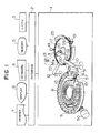
- Fig. 1 shows a single-line multi-item automatic chemical analyzer which has only single reaction vessel train.
- an analyzer main body 1 accommodates major mechanical elements the operations of which are controlled by a central processing unit (CPU) 3 through an interface 2.
- CPU central processing unit
- analysis conditions for the respective samples are inputted by a console panel such as a keyboard 4 and they are stored in a magnetic storage such as a random access memory 5A or a floppy disk 5B.
- Results of measurement in accordance with the analysis conditions are displayed on a display unit (for example, a VFD fluorescent display tube) 6 and printed out by a printer 7 for reporting the results.
- a sample disk 9 in which a number of sample Cups 8 are arranged is driven by a drive unit 50 to position each sample cup to a sample pickup position 51 sequentially.
- a sample pickup position 51 sequentially.
- certain amount of sample is sucked into a pipetting nozzle 52 from the sample cup by a sample pipetter 10 which has the pipetting nozzle 52, and a predetermined amount of sample for the test item is discharged from the nozzle 52 into a reaction vessel 11 which now stops at a discharge position 53 of a sample add station.
- the sample cup is kept stopped until the sampling by the sample pipetter 10 is carried out as many times as the number of test items.
- reaction vessels on a reaction disk 17 are sequentially positioned at a discharge position 53 as many times as the number of items and receive samples for the respective items.
- the nozzle of the sample pipetter 10 is positioned at a probe washing unit 24 and it is washed by washing liquid.
- the positions of the sample cups on the sample disk 9 are detected by a combination of a rotary detector and a photo-coupler detector as shown in JP-A-56-168555, and they are correlated by the CPU 3.
- a reagent disk 14 is arranged on an inner side of the sample disk 9.
- a number of reagent holders 15 are mounted on the reagent disk 14.
- a number of reagent bottles having fun-shaped section which contain reagents necessary for the measurement of the test items are mounted on the holders 15, with openings thereof being held downward.
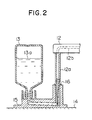
- a separate reagent nozzle tip 16 is inserted into an opening 55 (see Fig. 2) of each holder.
- Fig. 2 shows a construction in a vicinity of one of the reagent holders 15.
- the reagent holders of the same structure are circumferentially arranged on the reagent disk 14.
- Each reagent holder 15 is hollow and reagent liquid 13a from the reagent bottle 13 is supplied to the opening 55 through a hollow path 56 and it reaches a bottom of the removable nozzle tip 16.
- the reagent pipetter 12 in Figs. 1 and 2 has a nozzle mounting tube 12a which connects to a liquid suck/drain cylinge (not shown).
- a reagent is to be added to the reaction vessel 11 on the reaction disk 17
- the nozzle mounting tube 12a is moved.
- the reagent disk 14 is driven by a drive unit (not shown) so that the reagent bottle 13 corresponding to the test item for the reaction vessel stops at the reagent suck position 57 as the reaction vessel 11 to which the reagent is to be added is moved and stopped at the reagent add position of the reagent add station.
- the reagent pipetter 12 supplies a predetermined amount of reagent liquid into the nozzle tip 16 through a plunger hole 12b while the nozzle tip 16 for the corresponding reagent is fit to the end of the nozzle mounting tube 12a and the nozzle tip 16 is mounted on the opening 55, and the tip 16 is moved to the reaction vessel which is stopped at the reagent add position 60 and the reagent held in the tip 16 is discharged into the reaction vessel. Then, the tube 12a of the reagent pipetter 12 is moved to the reagent suck position 57 and descended, and the nozzle tip 16 is returned into the opening 55 of the original reagent holder 15.
- reagent supply unit which comprises the reagent disk 14 and the reagent pipetter 12 is shown, but another reagent supply unit which comprises similar reagent disk and reagent pipetter is arranged in the present analyzer, although it is omitted for simplication of the drawing.
- One of the reagent supply unit carries out the addition of a first reagent
- the other reagent supply unit carries out the addition of a second reagent.
- the first and second reagent add stations at which the reaction vessels stop are spoced from each other.
- the reaction disk 17 may carry out clockwise rotation by a stepping motor (not shown).
- Reaction vessels 11 which are of similar shape to that of the reaction vessels 11a, as shown in Fig. 7, are arranged on the reaction disk 17 at a constant pitch.
- the reaction vessel train which forms a closed loop is continuously driven by one revolution and one vessel pitch in each interval so that it next stops at an adjacent position of the previous stop position. In effect, it steps.
- the samples is added, the reagent is added and they are agitated by the agitator 18 at the corresponding station.
- the bottom of the reaction vessel train held on the reaction disk 17 is immersed into a constant temperature water tank 19, and the reaction vessel is directly measured at the measure station.
- a white light beam from a light source 20 of a photometer 58 which forms the measure station travels across the constant temperature water tank 19 and is directed to a spectroscope where it is spectroscoped by a diffraction grating 21.
- a plurality of monochromatic lights are detected by a multi-wavelength detector 22 such as a photo-diode array. The measurement is done while the reaction vessel train is driven.
- a signal from the detector based on the monochromatic light for measuring the test item of the reaction vessel which has moved across the light beam is selected, converted to a digital signal and stored in a memory 5A or 5B.
- the CPU 3 calculates a concentration or active value of the corresponding test item and displays a result on the display device 6 and prints it out by the printer 7.
- the stop position of the reaction vessel is shifted sequentially and clockwise.
- the stop position of the reaction disk 17 is shifted by one reaction vessel position in every 20 seconds. Thus, it takes 960 seconds (16 minutes) to pass through the 48 reaction vessel positions of the circumference. After one circulation of the reaction disk, the reaction vessel is washed by the washing device 25 for reuse.
- the washed reaction vessel is prepared for the analysis for the next sample.
- the first reagent is added at the first reagent add position 59
- the sample is added at the sample disharge position 53
- the second reagent is added at the second reagent add position 60.
- the analyzer is so programmed that when a reaction vessel assigned to a test item which requires a short analysis time is moved around the circumference and stopped at the washing device 25, the washing is carried out, but when a reaction vessel assigned to a test item which requires a long analysis time so that the reaction is not complete at the end of one circulation or to which the reagent is to be added three or more times is moved around the circumference and reaches the washing device 25, the washing device 25 does not carry out the washing.
- the second reaction vessel is renewed by the washing device before the first reaction vessel is next renewed by the washing device 25, and a new test item is assigned to the second reaction vessel.
- the analyzer of Fig. 1 once an operator inputs the analysis conditions for the test items for the respective samples, the analyzer controls the respective analysis times to continuously carry out the analysis required for the samples without requesting to the operator to classify the samples by the analysis time.
- Fig. 3 shows a time chart in one machine cycle for illustrating operation timings of the respective elements in the analyzer of Fig. 1.
- a detection disk for detecting the positions of the reaction vessels on the reaction disk is fixed to a rotary shaft mounted at a rotation center of the reaction disk 17, and a disk-like gear for transmitting a driving force of a stepping motor which serves as a drive source to the reaction disk is also fixed to the rotary shaft.
- the detection disk has as many detecting holes as the number of reaction vessels on the reaction disk and a light hole for detecting the reference position. Those holes are detected by photo-couplers and detection signals are supplied to the control unit.
- the control unit 3 detects the numbers or positions of the reaction vessels on the reaction disk 17 based on the detection signals from the photo-couplers and stores them in the memory unit 5.
- the relationship between the types of test items inputted from the input device 4 and the numbers or positions of the reaction vessels is also stored in the memory unit 5, and the analysis times for the test items are also stored in the memory unit 5.
- the control unit 3 may exchangeably assign a test item to each reaction vessel based on the stored information and may correctly control the renewal timing of each reaction vessel.
- the measurement conditions to be stored in the memory unit 5 may include the renewal time of the reaction vessel, that is, the analysis time, the need for adding the reagents, the codes of reagents to be used, the times to add the sample and the reagent, the measurement mode, the wavelength of the monochromatic light, the amounts of the sample and the reagent to be added and the data processing method.
- the measurement conditions of the test item are automatically stored in the memory unit 5 by mere selection of the item by the operator through the console panel 4.
- the operator inputs the test items required for each sample to be analyzed, through the console panel 4. Based on this input, the microcomputer determines the measurement conditions of each of the test items stored in the memory unit and the measurement sequence in connection with the position of the reaction vessel, and programs how to control the entire reaction line.
- the sample is sucked and discharged in accordance with the analysis condition, and the first and second reagents are sucked and discharged as required and then they are agitated. If the CPU determine that the addition of a third reagent is necessary or the reaction should be extended beyond 16 minutes, that is, into the second or subsequent circulation, based on the input analysis condition, the reaction vessel does not proceed to the measurement, data processing and washing of the reaction vessel, but the reaction vessel is sent into the next circulation (second circulation) to permit the addition of the third and fourth reagents.
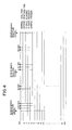
- Fig. 4 shows an example of a table stored for controlling the reaction line when the multi-item analysis is carried out by the analyzer of Fig. 1.
- Vertical lines represent operations.
- the vessel renew time is delayed 23 seconds, for example, in the cells No. 2 et seq in the actual operation, but they are shown without vessel renew time shift in order to facilitate the comparison of the items.
- an abscissa represents a time
- S means the addition of the sample
- R1 means the addition of the first reagent
- R2 means the addition of the second reagent.
- MIX means the mixing.
- the time period from the first reaction vessel renewal to the next reaction vessel renewal corresponds to one circulation of the reaction vessel train.
- a test item which requires a short analysis time is first assigned to the reaction vessel cell No. 1, and after one circulation, the reaction vessel is washed and renewed, and in a second circulation, a test item which requires a short analysis time for a new reagent is assigned.
- the sample and the first and second reagents are added in the first circulation of the reaction vessel train, and the reaction continues in the second circulation.
- the third reagent is added by the first reagent supply device in the second circulation, and after two circulataions, the reaction vessel is renewed.
- the third reagent is added by the first reagent supply device and the fourth reagent is added by the second reagent supply device in the second circulation.
- reaction vessel cell No. 5 in Fig. 4 no sample is added in the first circulation of the reaction vessel train but only the first reagent is added, and the sample is added in the second circulation to start the reaction. In this case, the preincuvation of the reagent is facilitated and the measurement of the reagent blank is also facilitated. Up to the cell No. 5, the reaction vessels are circulated up to twice although the circulation of three times or more may be set as required.
- Fig. 5 shows a decision flow chart of a reaction process when the analyzer of Fig. 2 is operated. It shows a process including steps 101 to 120. The decision shown in Fig. 5 is made for each reaction vessel renewed on the reaction disk and the process is proceeded by the microcomputer.
- test items requiring a short analysis time are GOT and GPT
- test items which require the analysis time of two or more circulations are cancer embryonic antigen (CEA) and L-malic acid in foods.
- CEA cancer embryonic antigen
- L-malic acid in foods.
- the first reagent in the measurement of the CEA is buffer solution
- the second reagent is antibody sensitive latex solution
- a wavelength for the measurement is 660 nm.
- the fourth reagent is used as it is in the cell No. 4 of Fig. 4.
- the first reagent is mixture of buffer solution and L-glutanic acid
- the second reagent is NAD containing solution
- the third reagent is GOT containing solution
- the fourth reagent is MDH (malic acid dehydrogenated acid) containg solution.
- An immunological measurement mechod which has recently been sapidly developed has been attracting notice as a methods which allows detection of an extremely small amount of physiological active material (holmon, etc.) or a very small amount of disease-related material.
- a principle of the immunological measurement method is to optically detect a composite selectively coupled to a molecule to be measured by making use of an antigen/antibody reaction which has a very peculiar coupling characteristic.
- the measurement method which utilizes the antigen/antibody reaction exhibits a high peculiarity but a probability of collision of molecules required for the reaction is proportional to the reaction time because the object to be measured is of low concentration.
- the reaction time should be set long enough to increase the composite of the antigen/antibody.
- the number of times of circulation may be controlled in accordance with the analysis condition for each reaction vessel in the single-reaction line multi- analysis type automatic analyzer in order to alter the reaction time. Accordingly, the samples which require the analyses under different measurement conditions can be processed in one run. Further, since the reaction time is set by controlling the reaction vessel renew device, there is no waste of time. Since the comparison of the analysis condition is automatically made by the computer, there is no error. From a stand point of the operator, the operation is same as that of the existing single-line multi-items type automatic analyzer so long as the sample is same although the analysis condition is different.
- Fig. 6 shows an overall configuration of another embodiment of the present invention
- Fig. 7 illustrate a vicinity of a reaction vessel loader/unloader of the analyzer of Fig. 6.
- the like elements to those of the analyzer of Fig. 1 are designated by the like numerals.
- the analyzer of Fig. 6 differs from that of Fig. 1 in that a loader/unloader 23 for exchanging the reaction vessels in used as a vessel renew device, instead of the washing device.
- a reaction vessel 11b loaded on the reaction disk 17 is unloaded from the reaction disk by an unloader 23a after the reaction and it is disposed.
- a new reaction vessel 11a is louded to the empty position by a loader 23b.
- Unused reaction vessels llc are in a line and they are fed, one by one, to the loader position by a feeder 23c.
- the loader/unloader for the disposable reaction vessels is controlled in accordance with decision information as to whether the reaction is to be extended to the second circulation. Accordingly, the freedom of the analysis method of the automatic analyzer can be improved by a simple mechanical action of disposing or inserting the reaction vessel.
Abstract
Description
- The present invention relates to method and apparatus for analyzing a plurality of test items in liquid samples, and more particularly to method and apparatus switable for carrying out analysis for a plurality of test items on one reaction vessel train.
- As apparatus for carrying out the analysis for a plurality of test items by an automatic analyzer, a multi-item analyzer which has a plurality of reaction lines and reaction for each test item proceeds in each reaction line as disclosed in JP-B-57-21663, and a single-line multi-item analyzer which has only single reaction line and reaction for a plurality of test items proceed on the single reaction line as disclosed in JP-B-55-21303, have been known in the art. The latter is suitable for simplification of construction and it has been widely used.
- However, in the prior art single-line multi-item analyzer, the reaction line is composed of a reaction vessel train, and a sample supply device, a reagent supply device and a reaction vessel washing device are fixedly arranged around the reaction line so that each reaction vessel stopped at a reaction vessel washing position is cleaned. As a result, a maximum time period for which the sample may stay on the reaction line is one cycle time of the reaction vessels.
- On the other hand, where an extremely small quantity of component in vivo is to be analyzed by utilizing an antigen/antibody reaction, a long reaction time is frequently required. U.S. Patent 4,837,159 discloses an immunological analyzer which separates a bound (B) of an antigen and an antibody, and a free component (F) by cleaning. In the U.S. Patent, reaction containers are arranged on a turn table which forms a circular reaction line and enzyne immuno-assoy is carried out on the single reaction line.
- In the apparatus of the U.S. Patent, when a first group of samples are to be analyzed, time periods from the sampling to the washing are same for all samples supplied to the reaction line. After the first group of samples have been analyzed, an operating condition of the analyzer is modified for a group of samples to be analyzed next. Because of the modification of the operating condition of the analyzer, the time period from the sampling to the washing is set differently from that under the previous condition. However, the time periods from the sampling to the washing for those samples which are to be processed on the same reaction line are equal to each other.
- In the U.S. Patent 4,837,159, the analyzer is first used as a single-line single-item analyzer, and then used as the same analyzer for the next different items. Accordingly, it is very inconvenient when a plurality of test items are to be analyzed for each of many samples.
- It is an object of the present invention to provide method and apparatus for analyzing a plurality of test items which permit the analysis by applying a proper analysis time to each of samples even if samples for various test items which require different analysis times are placed on one reaction vessel train.
- It is another object of the present invention to provide method and apparatus for efficiently analyzing a plurality of test items when samples for the plurality of test items arranged on one reaction vessel train, which permit to change a stay time of the sample in the reaction vessel from test item to test item so that samples requiring a short stay time and samples requiring a long stay time may be mixedly placed.
- The present invention is applied to an automatic analyzer which intermittently drives a train of reaction vessels arranged in an endless fashion, causes a sample and reagent react in each reaction vessel, and causes any of the reaction vessels on the reaction vessel train stop at a sample add station and a vessel renew station.
- In accordance with the present invention, a plurality of test items which require different analysis times are supplied by sample supply means so that they are mixedly arranged on one reaction vessel train, and the reaction vessels on the reaction vessel train are selectively renewed in a sequence of the time-over of the analysis times of the respective test items.
-
- Fig. 1 shows an overall construction of a blood analyzer in accordance with one embodiment of the present invention,
- Fig. 2 shows a sectional view of a vicinity of a reagent holder in Fig. 1,
- Fig. 3 shows a timing chart for illustrating a relationship among elements of the analyzer in one machine cycle,
- Fig. 4 shows a reaction line control table which is used in multi-item analysis,
- Fig. 5 shows a flow chart of a control method when reactions for a plurality of samples are proceeded on a reaction vessel train,
- Fig. 6 shows an overall configuration of anather embodiment of the present invention, and
- Fig. 7 shows reaction vessel renew means in the analyzer of Fig. 6.
- A particular test item is related to each of reaction vessels on a reaction vessel train arranged in an endless fashion to form a reaction line, and when the reaction vessel is exchanged, a new test item is set to the reaction vessel. An analysis time of each of the test items is set to correspond to the number of times of circulation (number of cycles) of the reaction vessels on the reaction line. Each reaction vessel related to the test item has the number of cycles in which it remains on the reaction line controlled by a corresponding pre-inputted analysis condition, and the reaction vessel renew device is selectively controlled for each reaction vessel in accordance with the number of cycles. Thus, in the automatic analyzer, the test item which requires a short reaction time is processed in a smaller number of cycles of the reaction line (mostly in one cycle), and the test item which requires a long reaction time is processed in a larger number of cycles (mostly in two cycles or more). Thus, even if a plurality of test items which require different reaction times are requested for one sample, the automatic analyzer can sequentially process them.
- In a preferred embodiment of the present invention, an automatic analyzer which handles a plurality of test items on one reaction vessel train comprises a device for inputting an analysis time and the number of reagents to be added for each test item, and a memory for storing the input information. The stored input information and the reaction vessel for the corresponding test item are compared. If the time required for one circulation of the endless reaction vessel train is longer than the analysis time of the test item, the content (reaction liquid) of the reaction vessel is not disposed and the analysis time is extended to the next cycle.
- When reaction for the plurality of test items are to be proceeded on one reaction vessel train, either the sample or the reagent may be applied earlier to the reaction vessel. Means for driving the reaction vessel train is preferably a reaction table which is intermittently rotated by a drive source although any means which cyclically drives the reaction vessel train may be used. For example, separate vessel holders may be coupled in chain and the entire chain is rotated, or a plurality of cassette type holders which can accommodate a plurality of reaction vessels may be arranged and they may be rotated to move along a predetermined path. For a sake of explanation, a turn table is used in the following explanation.
- The reaction vessel train is intermittently driven along a predetermined path. The path along which the reaction vessel line is driven is usually called a reaction line. Defined on the reaction lines are an agent add station, a sample add station, an agitate station, a measure station and a vessel renew station. At the reagent add station, a reagent for a test item is discharged from a nozzzle of an agent add device into the reaction vessel. At the sample add station, a sample piched up from the sample vessel on the sampler is dischaged by a nozzle of a sample add device into the reaction vessel by a predetermined quantity. At the measure station, a light is irradiated to the reaction vessel and a transmitted light or fluorescent light from the reaction vessel in measured. At the vessel renew station, a vessel renew device acts on the stationary reaction vessel. Namely, reaction liquid is ejected from the reaction vessel by a nozzle to dispose the content of the reaction vessel and wash it by washing liquid, or the reaction vessel which contains the reaction liquid is unloaded for disposition and a new reaction vessel is loaded. An example of the vessel renew device is a reaction vessel washing device or a reaction vessel load/unload device.
- Where a reaction table which holds a number of reaction vessels is used, the arive and the stop are applied to the reaction table. In some cases, the vibration may also be applied to the reaction table for the agitation of the reaction table. While the reaction table stops for processing the reaction vessels, the processings by the respective devices are selectively carried out for the reaction vessels which stop at the reagent add station or the vessel renew station, in accordance with the decision as to whether such processings are needed. In this case, the reaction continues in those reaction vessels on the same reaction table for which both the reagents and the samples have already been added.
- The analysis time usually means a time period from the renewal of the reaction vessel to the next renewal, but in some cases it means a time period from the first addition of the sample or the reagent into the reaction vessel to the renewal of the vessel. The reaction time usually means a time period from the accommodation of both the sample and the reagent in the reaction vessel to the end of measurement, but in some cases it means a time period from the start of reaction to the renewal of the reaction vessel, or a time period from the start of a specific reaction to the start of a next reaction where a plurality of reactions are included.
- In a preferred embodiment of the present invention, after the reaction vessel train has received one or both of the samples and the reagents, the reaction table is driven by one revolution and one vessel pitch and stopped thereat, although the, reaction vessel train may be driven in other way, for example, step by step for each vessel pitch or a plural-vessel pitch. One circulation of the reaction vessel train usually means a cycle in which a reaction vessel renewed at the reaction vessel renew station is moved past the sample add station and the reagent add station and stopped at the same vessel renew station. One cycle may also be used to represent the same meaning as one circulation.
- In a preferred embodiment of the present invention, even if three or more reagents are to be used for a specific analysis item and the reagents are to be added three times or more, the positions at which the reaction vessels are stopped for the addition of the reagents may be only two on the reaction vessel train. For the test item which requires the addition of the reagents three times, the stored analysis condition and the reaction vessel for the test item are compared, and in the first circulation of the reaction vessel train, the content (including sample, first reagent and second reagent) in the reaction vessel corresponding to the test item is not discorded but it is continuously kept in the second and subsequent circulations. In the second and subsequent circulations, a third reagent (and a fourth reagent if necessary) are selectively added to the corresponding reaction vessel.
- A memory unit of the automatic analyzer in accordance with the present invention comprises a random access memory which allows modification of data and a non-volatile memory such as a floppy disk. The memory unit which comprises those memories stores sample numbers of samples to be processed in the same day, types of test items, a relation between positions of the reaction vessel on the reaction table and the test items, and a control program for the samples. The non-volatite memory stores measurement condition data for each of the test items which may be tested by the analyzer and predetermined operating conditions of the respective elements.
- The memory unit stores the information by securing a memory area for the number of times of circulation required for each of the reaction vessels on the reaction vessel train to store messurement data from a detector such as a photometer.
- Embodiments of the present invention are now explained with reference to the drawings.
- One embodiment of the present invention is now explained with reference to Figs. 1 to 5. Fig. 1 shows a single-line multi-item automatic chemical analyzer which has only single reaction vessel train.
- In Fig. 1, an analyzer
main body 1 accommodates major mechanical elements the operations of which are controlled by a central processing unit (CPU) 3 through aninterface 2. Where a sample like body fluid is to be analyzed, analysis conditions for the respective samples are inputted by a console panel such as akeyboard 4 and they are stored in a magnetic storage such as a random access memory 5A or a floppy disk 5B. Results of measurement in accordance with the analysis conditions are displayed on a display unit (for example, a VFD fluorescent display tube) 6 and printed out by aprinter 7 for reporting the results. - A
sample disk 9 in which a number ofsample Cups 8 are arranged is driven by adrive unit 50 to position each sample cup to a sample pickup position 51 sequentially. When one of the sample cups 8 which contains the body liquid reaches the sample pickup position and stops thereat, certain amount of sample is sucked into a pipetting nozzle 52 from the sample cup by asample pipetter 10 which has the pipetting nozzle 52, and a predetermined amount of sample for the test item is discharged from the nozzle 52 into a reaction vessel 11 which now stops at a discharge position 53 of a sample add station. Where the sample in the sample cup which now stops at the pickup position 51 requires a plurality of test items, the sample cup is kept stopped until the sampling by thesample pipetter 10 is carried out as many times as the number of test items. On the other hand, during this period, reaction vessels on areaction disk 17 are sequentially positioned at a discharge position 53 as many times as the number of items and receive samples for the respective items. After the sampling for the plurality of test items for one sample has been completed, the nozzle of thesample pipetter 10 is positioned at aprobe washing unit 24 and it is washed by washing liquid. - The positions of the sample cups on the
sample disk 9 are detected by a combination of a rotary detector and a photo-coupler detector as shown in JP-A-56-168555, and they are correlated by theCPU 3. - A
reagent disk 14 is arranged on an inner side of thesample disk 9. A number ofreagent holders 15 are mounted on thereagent disk 14. A number of reagent bottles having fun-shaped section which contain reagents necessary for the measurement of the test items are mounted on theholders 15, with openings thereof being held downward. A separatereagent nozzle tip 16 is inserted into an opening 55 (see Fig. 2) of each holder. - Fig. 2 shows a construction in a vicinity of one of the
reagent holders 15. The reagent holders of the same structure are circumferentially arranged on thereagent disk 14. Eachreagent holder 15 is hollow and reagent liquid 13a from thereagent bottle 13 is supplied to the opening 55 through a hollow path 56 and it reaches a bottom of theremovable nozzle tip 16. - The
reagent pipetter 12 in Figs. 1 and 2 has anozzle mounting tube 12a which connects to a liquid suck/drain cylinge (not shown). When a reagent is to be added to the reaction vessel 11 on thereaction disk 17, thenozzle mounting tube 12a is moved. Thereagent disk 14 is driven by a drive unit (not shown) so that thereagent bottle 13 corresponding to the test item for the reaction vessel stops at the reagent suck position 57 as the reaction vessel 11 to which the reagent is to be added is moved and stopped at the reagent add position of the reagent add station. Thereagent pipetter 12 supplies a predetermined amount of reagent liquid into thenozzle tip 16 through aplunger hole 12b while thenozzle tip 16 for the corresponding reagent is fit to the end of thenozzle mounting tube 12a and thenozzle tip 16 is mounted on the opening 55, and thetip 16 is moved to the reaction vessel which is stopped at the reagent addposition 60 and the reagent held in thetip 16 is discharged into the reaction vessel. Then, thetube 12a of thereagent pipetter 12 is moved to the reagent suck position 57 and descended, and thenozzle tip 16 is returned into the opening 55 of theoriginal reagent holder 15. - In Fig. 1, only one reagent supply unit which comprises the
reagent disk 14 and thereagent pipetter 12 is shown, but another reagent supply unit which comprises similar reagent disk and reagent pipetter is arranged in the present analyzer, although it is omitted for simplication of the drawing. One of the reagent supply unit carries out the addition of a first reagent, and the other reagent supply unit carries out the addition of a second reagent. In this case, the first and second reagent add stations at which the reaction vessels stop are spoced from each other. - The
reaction disk 17 may carry out clockwise rotation by a stepping motor (not shown). Reaction vessels 11 which are of similar shape to that of the reaction vessels 11a, as shown in Fig. 7, are arranged on thereaction disk 17 at a constant pitch. The reaction vessel train which forms a closed loop is continuously driven by one revolution and one vessel pitch in each interval so that it next stops at an adjacent position of the previous stop position. In effect, it steps. During a stop period between drives, the samples is added, the reagent is added and they are agitated by theagitator 18 at the corresponding station. - The bottom of the reaction vessel train held on the
reaction disk 17 is immersed into a constant temperature water tank 19, and the reaction vessel is directly measured at the measure station. a white light beam from alight source 20 of a photometer 58 which forms the measure station travels across the constant temperature water tank 19 and is directed to a spectroscope where it is spectroscoped by a diffraction grating 21. A plurality of monochromatic lights are detected by amulti-wavelength detector 22 such as a photo-diode array. The measurement is done while the reaction vessel train is driven. Each time one of the reaction vessels 11 moves across the light beam of the photometer, a signal from the detector based on the monochromatic light for measuring the test item of the reaction vessel which has moved across the light beam is selected, converted to a digital signal and stored in a memory 5A or 5B. After a plurality of measurement signals for one reaction vessel have been produced, theCPU 3 calculates a concentration or active value of the corresponding test item and displays a result on thedisplay device 6 and prints it out by theprinter 7. - If a particular reaction vessel on the
reaction disk 17 is looked at, the stop position of the reaction vessel is shifted sequentially and clockwise. In the present analyzer, the stop position of thereaction disk 17 is shifted by one reaction vessel position in every 20 seconds. Thus, it takes 960 seconds (16 minutes) to pass through the 48 reaction vessel positions of the circumference. After one circulation of the reaction disk, the reaction vessel is washed by thewashing device 25 for reuse. - The washed reaction vessel is prepared for the analysis for the next sample. For the reaction vessel washed by the
washing device 25, the first reagent is added at the first reagent addposition 59, the sample is added at the sample disharge position 53, and the second reagent is added at the second reagent addposition 60. The analyzer is so programmed that when a reaction vessel assigned to a test item which requires a short analysis time is moved around the circumference and stopped at thewashing device 25, the washing is carried out, but when a reaction vessel assigned to a test item which requires a long analysis time so that the reaction is not complete at the end of one circulation or to which the reagent is to be added three or more times is moved around the circumference and reaches thewashing device 25, thewashing device 25 does not carry out the washing. - When a test item which requires a short analysis time is assigned to a second reaction vessel washed by the
washing device 25 after the washing of a first reaction vessel to which a test item which requires a long analysis time has been assigned, the second reaction vessel is renewed by the washing device before the first reaction vessel is next renewed by thewashing device 25, and a new test item is assigned to the second reaction vessel. In the analyzer of Fig. 1, once an operator inputs the analysis conditions for the test items for the respective samples, the analyzer controls the respective analysis times to continuously carry out the analysis required for the samples without requesting to the operator to classify the samples by the analysis time. - Fig. 3 shows a time chart in one machine cycle for illustrating operation timings of the respective elements in the analyzer of Fig. 1.
- The detection of all reaction vessels 11 on the
reaction disk 17 in the analyzer of Fig. 1 is correlated with the positions of other elements by a microcomputer of theCPU 3 by counting the vessels with reference to one location. A method disclosed, in U.S. Patent 4,313,735 may be used to detect the position of the reaction vessel on the reaction disk. - A detection disk for detecting the positions of the reaction vessels on the reaction disk is fixed to a rotary shaft mounted at a rotation center of the
reaction disk 17, and a disk-like gear for transmitting a driving force of a stepping motor which serves as a drive source to the reaction disk is also fixed to the rotary shaft. The detection disk has as many detecting holes as the number of reaction vessels on the reaction disk and a light hole for detecting the reference position. Those holes are detected by photo-couplers and detection signals are supplied to the control unit. - In the analyzer of Fig. 1, the
control unit 3 detects the numbers or positions of the reaction vessels on thereaction disk 17 based on the detection signals from the photo-couplers and stores them in thememory unit 5. The relationship between the types of test items inputted from theinput device 4 and the numbers or positions of the reaction vessels is also stored in thememory unit 5, and the analysis times for the test items are also stored in thememory unit 5. Thus, thecontrol unit 3 may exchangeably assign a test item to each reaction vessel based on the stored information and may correctly control the renewal timing of each reaction vessel. - When a body fluid sample such as blood is to be analyzed by the analyzer of Fig. 1, the operator inputs from the
console panel 4 necessary combinations of measurement conditions for all test items to be analyzed by the analyzer. The measurement conditions to be stored in thememory unit 5 may include the renewal time of the reaction vessel, that is, the analysis time, the need for adding the reagents, the codes of reagents to be used, the times to add the sample and the reagent, the measurement mode, the wavelength of the monochromatic light, the amounts of the sample and the reagent to be added and the data processing method. - Once the measurement conditions have been stored for each test item by the input operation, the measurement conditions of the test item are automatically stored in the
memory unit 5 by mere selection of the item by the operator through theconsole panel 4. - When the analyzer is to be operated, the operator inputs the test items required for each sample to be analyzed, through the
console panel 4. Based on this input, the microcomputer determines the measurement conditions of each of the test items stored in the memory unit and the measurement sequence in connection with the position of the reaction vessel, and programs how to control the entire reaction line. - When the multi-item analysis operation by the analyzer is started, the sample is sucked and discharged in accordance with the analysis condition, and the first and second reagents are sucked and discharged as required and then they are agitated. If the CPU determine that the addition of a third reagent is necessary or the reaction should be extended beyond 16 minutes, that is, into the second or subsequent circulation, based on the input analysis condition, the reaction vessel does not proceed to the measurement, data processing and washing of the reaction vessel, but the reaction vessel is sent into the next circulation (second circulation) to permit the addition of the third and fourth reagents.
- Fig. 4 shows an example of a table stored for controlling the reaction line when the multi-item analysis is carried out by the analyzer of Fig. 1. Vertical lines represent operations. In the present example of combination of the analysis conditions, the vessel renew time is delayed 23 seconds, for example, in the cells No. 2 et seq in the actual operation, but they are shown without vessel renew time shift in order to facilitate the comparison of the items. In Fig. 4, an abscissa represents a time, S means the addition of the sample, R1 means the addition of the first reagent, and R2 means the addition of the second reagent. MIX means the mixing. The time period from the first reaction vessel renewal to the next reaction vessel renewal corresponds to one circulation of the reaction vessel train.
- In Fig. 4, it is seen that a test item which requires a short analysis time is first assigned to the reaction vessel cell No. 1, and after one circulation, the reaction vessel is washed and renewed, and in a second circulation, a test item which requires a short analysis time for a new reagent is assigned. For a test item assigned to the reaction vessel cell No. 2, the sample and the first and second reagents are added in the first circulation of the reaction vessel train, and the reaction continues in the second circulation. For the test item assigned to the reaction vessel cell No. 3, the sample and the first and second reagents are added in the first circulation, the third reagent is added by the first reagent supply device in the second circulation, and after two circulataions, the reaction vessel is renewed. For the reaction vessel cell No. 4, the third reagent is added by the first reagent supply device and the fourth reagent is added by the second reagent supply device in the second circulation.
- For the reaction vessel cell No. 5 in Fig. 4, no sample is added in the first circulation of the reaction vessel train but only the first reagent is added, and the sample is added in the second circulation to start the reaction. In this case, the preincuvation of the reagent is facilitated and the measurement of the reagent blank is also facilitated. Up to the cell No. 5, the reaction vessels are circulated up to twice although the circulation of three times or more may be set as required.
- Fig. 5 shows a decision flow chart of a reaction process when the analyzer of Fig. 2 is operated. It shows a process including steps 101 to 120. The decision shown in Fig. 5 is made for each reaction vessel renewed on the reaction disk and the process is proceeded by the microcomputer.
- By carrying out the process of Fig. 5 to each reaction vessel as the
reaction disk 17 is moved, samples are supplied to the reaction vessels such that various items requiring different time periods to be stayed on the reaction line are mixedly arranged on thereaction disk 17, and proper reaction for each item is proceeded under the mixed arrangement. The reaction solutions after the measurement are selectively discharged from the reaction vessels on the reaction table by thewashing device 25 is a sequence of expiration of the analysis time assigned to each test item and the reaction vessels are washed and renewed. New test items are assigned to the renewed reaction vessel in a sequence of renewal. - Examples of test items requiring a short analysis time are GOT and GPT, and examples of test items which require the analysis time of two or more circulations are cancer embryonic antigen (CEA) and L-malic acid in foods. Of those, the CEA is analyzed by the same control as that for the item analyzed for the cell No. 2 of Fig. 4. The first reagent in the measurement of the CEA is buffer solution, the second reagent is antibody sensitive latex solution, and a wavelength for the measurement is 660 nm. In the analysis of the L-malic acid, the fourth reagent is used as it is in the cell No. 4 of Fig. 4. In this case, the first reagent is mixture of buffer solution and L-glutanic acid, the second reagent is NAD containing solution, the third reagent is GOT containing solution, and the fourth reagent is MDH (malic acid dehydrogenated acid) containg solution.
- An immunological measurement mechod which has recently been sapidly developed has been attracting notice as a methods which allows detection of an extremely small amount of physiological active material (holmon, etc.) or a very small amount of disease-related material. A principle of the immunological measurement method is to optically detect a composite selectively coupled to a molecule to be measured by making use of an antigen/antibody reaction which has a very peculiar coupling characteristic. The measurement method which utilizes the antigen/antibody reaction exhibits a high peculiarity but a probability of collision of molecules required for the reaction is proportional to the reaction time because the object to be measured is of low concentration. Thus, in order to attain a sufficient sensitivity, the reaction time should be set long enough to increase the composite of the antigen/antibody.
- By applying the present invention, a known oxygen measurement method in which the reaction is completed in approximately 10 minutes and the immunological measurement method which requires the avalysis time of 30 minutes or longer may be proceeded parallelly on the same reaction line.
- In accordance with the embodiment of Fig. 1, the number of times of circulation may be controlled in accordance with the analysis condition for each reaction vessel in the single-reaction line multi- analysis type automatic analyzer in order to alter the reaction time. Accordingly, the samples which require the analyses under different measurement conditions can be processed in one run. Further, since the reaction time is set by controlling the reaction vessel renew device, there is no waste of time. Since the comparison of the analysis condition is automatically made by the computer, there is no error. From a stand point of the operator, the operation is same as that of the existing single-line multi-items type automatic analyzer so long as the sample is same although the analysis condition is different.
- Fig. 6 shows an overall configuration of another embodiment of the present invention, and Fig. 7 illustrate a vicinity of a reaction vessel loader/unloader of the analyzer of Fig. 6. In the analyzer of Fig. 6, the like elements to those of the analyzer of Fig. 1 are designated by the like numerals. The analyzer of Fig. 6 differs from that of Fig. 1 in that a loader/
unloader 23 for exchanging the reaction vessels in used as a vessel renew device, instead of the washing device. - As shown in Fig. 7, a reaction vessel 11b loaded on the
reaction disk 17 is unloaded from the reaction disk by anunloader 23a after the reaction and it is disposed. At the next position, a new reaction vessel 11a is louded to the empty position by aloader 23b. Unused reaction vessels llc are in a line and they are fed, one by one, to the loader position by afeeder 23c. - In accordance with the embodiment of Fig. 6, the loader/unloader for the disposable reaction vessels is controlled in accordance with decision information as to whether the reaction is to be extended to the second circulation. Accordingly, the freedom of the analysis method of the automatic analyzer can be improved by a simple mechanical action of disposing or inserting the reaction vessel.
Claims (15)
sample supply means (10) for supplying samples to one reaction vessel train such that a plurality of test items requiring different analysis times are mixedly arranged; and
vessel renew means (25, 23) for selectively renewing the reaction vessels on the reaction vessel train in accordance with analysis times necessary for the respective test items.
memory means for storing the analysis times for the respective test items; and
control means for controlling the operation of said vessel renew means in accordance with relationship between a position or number of the reaction vessel to which a sample has been supplied by said sample supply means and a type of test item, and the analysis time stored in said memory means.
a first reagent supply device for supplying reagents firstly and thirdly to the reaction vessels on the reaction vessel train; and
a second reagent supply device for supplying agent secondly to the reaction vessel.
supplying samples such that a plurality of test items requiring different analysis times are mixedly arranged on one reaction vessel train; and
selectively renewing the reaction vessels on the reaction vessel train in a sequence of expiration of the analysis times for the test items.
Applications Claiming Priority (2)
| Application Number | Priority Date | Filing Date | Title |
|---|---|---|---|
| JP1182661A JP2539512B2 (en) | 1989-07-17 | 1989-07-17 | Multi-item analyzer and method for operating the analyzer |
| JP182661/89 | 1989-07-17 |
Publications (2)
| Publication Number | Publication Date |
|---|---|
| EP0409126A2 true EP0409126A2 (en) | 1991-01-23 |
| EP0409126A3 EP0409126A3 (en) | 1991-08-28 |
Family
ID=16122223
Family Applications (1)
| Application Number | Title | Priority Date | Filing Date |
|---|---|---|---|
| EP19900113549 Withdrawn EP0409126A3 (en) | 1989-07-17 | 1990-07-16 | Method and apparatus for automatically analyzing a plurality of text items |
Country Status (4)
| Country | Link |
|---|---|
| US (1) | US5434083A (en) |
| EP (1) | EP0409126A3 (en) |
| JP (1) | JP2539512B2 (en) |
| CA (1) | CA2021054A1 (en) |
Cited By (15)
| Publication number | Priority date | Publication date | Assignee | Title |
|---|---|---|---|---|
| EP0488247A2 (en) * | 1990-11-28 | 1992-06-03 | Hitachi, Ltd. | Analyzing method and apparatus for liquid sample |
| DE4231172A1 (en) * | 1991-09-18 | 1993-04-08 | Hitachi Ltd | AUTOMATIC ANALYZER FOR CLINICAL EXAMINATIONS |
| US5376313A (en) * | 1992-03-27 | 1994-12-27 | Abbott Laboratories | Injection molding a plastic assay cuvette having low birefringence |
| WO1995008774A2 (en) * | 1993-09-24 | 1995-03-30 | Abbott Laboratories | Automated continuous and random access analytical system and components thereof |
| EP0746769A4 (en) * | 1992-03-27 | 1995-04-07 | Abbott Lab | Automated continuous and random access analytical system and components thereof |
| EP0755519A4 (en) * | 1992-03-27 | 1995-04-07 | Abbott Lab | Automated continuous and random access analytical system and components thereof |
| US5635364A (en) | 1992-03-27 | 1997-06-03 | Abbott Laboratories | Assay verification control for an automated analytical system |
| WO1997022006A1 (en) * | 1995-12-14 | 1997-06-19 | Beckman Instruments, Inc. | Improved automated random access analyzer |
| US5646049A (en) | 1992-03-27 | 1997-07-08 | Abbott Laboratories | Scheduling operation of an automated analytical system |
| US6190617B1 (en) | 1992-03-27 | 2001-02-20 | Abbott Laboratories | Sample container segment assembly |
| US7666602B2 (en) | 1998-05-01 | 2010-02-23 | Gen-Probe Incorporated | Method for agitating the fluid contents of a container |
| US7794659B2 (en) | 2005-03-10 | 2010-09-14 | Gen-Probe Incorporated | Signal measuring system having a movable signal measuring device |
| US8192992B2 (en) | 1998-05-01 | 2012-06-05 | Gen-Probe Incorporated | System and method for incubating the contents of a reaction receptacle |
| US8718948B2 (en) | 2011-02-24 | 2014-05-06 | Gen-Probe Incorporated | Systems and methods for distinguishing optical signals of different modulation frequencies in an optical signal detector |
| US9046507B2 (en) | 2010-07-29 | 2015-06-02 | Gen-Probe Incorporated | Method, system and apparatus for incorporating capacitive proximity sensing in an automated fluid transfer procedure |
Families Citing this family (56)
| Publication number | Priority date | Publication date | Assignee | Title |
|---|---|---|---|---|
| US6436349B1 (en) * | 1991-03-04 | 2002-08-20 | Bayer Corporation | Fluid handling apparatus for an automated analyzer |
| US5610069A (en) | 1992-03-27 | 1997-03-11 | Abbott Laboratories | Apparatus and method for washing clinical apparatus |
| US5627522A (en) | 1992-03-27 | 1997-05-06 | Abbott Laboratories | Automated liquid level sensing system |
| US5536471A (en) | 1992-03-27 | 1996-07-16 | Abbott Laboratories | Syringe with bubble flushing |
| US5540890A (en) | 1992-03-27 | 1996-07-30 | Abbott Laboratories | Capped-closure for a container |
| US5960160A (en) | 1992-03-27 | 1999-09-28 | Abbott Laboratories | Liquid heater assembly with a pair temperature controlled electric heating elements and a coiled tube therebetween |
| US5575978A (en) | 1992-03-27 | 1996-11-19 | Abbott Laboratories | Sample container segment assembly |
| US5578494A (en) | 1992-03-27 | 1996-11-26 | Abbott Laboratories | Cap actuator for opening and closing a container |
| US5507410A (en) | 1992-03-27 | 1996-04-16 | Abbott Laboratories | Meia cartridge feeder |
| US5605665A (en) | 1992-03-27 | 1997-02-25 | Abbott Laboratories | Reaction vessel |
| DE69515565T2 (en) * | 1994-07-15 | 2000-11-02 | Dade Chemistry Systems Inc | Analyzer |
| JP3251441B2 (en) * | 1994-09-30 | 2002-01-28 | シスメックス株式会社 | Cuvette and cuvette transporter |
| JP3229915B2 (en) * | 1995-01-19 | 2001-11-19 | 日本電子株式会社 | Biochemical automatic analyzer |
| US5631166A (en) * | 1995-03-21 | 1997-05-20 | Jewell; Charles R. | Specimen disk for blood analyses |
| JP3063584B2 (en) * | 1995-09-05 | 2000-07-12 | 株式会社日立製作所 | Automatic analyzer |
| JP2988362B2 (en) * | 1996-03-11 | 1999-12-13 | 株式会社日立製作所 | Multi-sample analysis system |
| US6733728B1 (en) * | 1996-03-11 | 2004-05-11 | Hitachi, Ltd. | Analyzer system having sample rack transfer line |
| ES2245462T3 (en) * | 1996-04-26 | 2006-01-01 | Dade Behring Inc. | PROCEDURE AND APPLIANCE TO PORTRAIT SAMPLES IN AN AUTOMATIC CHEMICAL ANALYZER. |
| US5795784A (en) | 1996-09-19 | 1998-08-18 | Abbott Laboratories | Method of performing a process for determining an item of interest in a sample |
| US5856194A (en) | 1996-09-19 | 1999-01-05 | Abbott Laboratories | Method for determination of item of interest in a sample |
| USD404830S (en) * | 1996-11-19 | 1999-01-26 | Universal Healthwatch, Inc. | Multi-sided medical diagnostic test device |
| US6193933B1 (en) * | 1997-10-27 | 2001-02-27 | Hitachi, Ltd. | Automatic analysis apparatus |
| JP3525757B2 (en) * | 1998-09-18 | 2004-05-10 | 株式会社日立製作所 | Chemical analyzer |
| US7390459B2 (en) * | 1999-12-13 | 2008-06-24 | Illumina, Inc. | Oligonucleotide synthesizer |
| JP2004507337A (en) * | 1999-12-13 | 2004-03-11 | イルミナ インコーポレイテッド | Oligonucleotide synthesizer |
| JP2002048802A (en) * | 2000-08-07 | 2002-02-15 | Hitachi Ltd | Automatic analysis system |
| US6825041B2 (en) | 2001-03-16 | 2004-11-30 | Beckman Coulter, Inc. | Method and system for automated immunochemistry analysis |
| US20030045003A1 (en) * | 2001-07-20 | 2003-03-06 | Smith Jack V. | Method for detection of the adulterant urine luckTM in urine using liquid chemistry, dry chemistry test pads, and lateral flow |
| US7015042B2 (en) * | 2001-07-27 | 2006-03-21 | Dade Behring Inc. | Increasing throughput in an automatic clinical analyzer by partitioning assays according to type |
| US7338803B2 (en) * | 2003-07-18 | 2008-03-04 | Dade Behring Inc. | Method for increasing capacity in an automatic clinical analyzer by using modular reagent delivery means |
| US7842504B2 (en) * | 2004-04-02 | 2010-11-30 | Siemens Healthcare Diagnostics Inc. | Method for increasing throughput in an automatic clinical analyzer by duplicating reagent resources |
| US20050249634A1 (en) * | 2004-05-10 | 2005-11-10 | Devlin William J Sr | Calibration solution system for use in an automatic clinical analyzer |
| US9459269B2 (en) * | 2005-07-22 | 2016-10-04 | Siemens Healthcare Diagnostics Inc. | Assay timing in a clinical analyzer using a cuvette carrier |
| JP5055282B2 (en) * | 2005-09-14 | 2012-10-24 | イルミナ インコーポレイテッド | Continuous polymer synthesizer |
| US8153061B2 (en) * | 2005-11-23 | 2012-04-10 | Siemens Healthcare Diagnostics Inc. | Storage and supply system for clinical solutions used in an automatic analyzer |
| TWI310835B (en) * | 2006-06-23 | 2009-06-11 | Ind Tech Res Inst | Gravity-driven fraction separator and method thereof |
| WO2008092155A2 (en) * | 2007-01-26 | 2008-07-31 | Illumina, Inc. | Image data efficient genetic sequencing method and system |
| US8315817B2 (en) | 2007-01-26 | 2012-11-20 | Illumina, Inc. | Independently removable nucleic acid sequencing system and method |
| JP4659054B2 (en) * | 2008-02-27 | 2011-03-30 | 株式会社日立ハイテクノロジーズ | Automatic analyzer |
| JP4793413B2 (en) * | 2008-07-30 | 2011-10-12 | 株式会社島津製作所 | Differential refractive index detector |
| CN101726616B (en) * | 2008-10-31 | 2014-07-16 | 深圳迈瑞生物医疗电子股份有限公司 | Automatic analytic device and working method thereof |
| US9073033B2 (en) | 2010-01-19 | 2015-07-07 | Illumina, Inc. | Methods and compositions for processing chemical reactions |
| JP5674440B2 (en) * | 2010-12-01 | 2015-02-25 | 株式会社日立ハイテクノロジーズ | Automatic analyzer |
| JP2013036891A (en) * | 2011-08-09 | 2013-02-21 | Beckman Coulter Inc | Analyzer and analysis method |
| JP6071384B2 (en) * | 2012-09-27 | 2017-02-01 | 東芝メディカルシステムズ株式会社 | Automatic analyzer |
| JP6165961B2 (en) | 2013-03-15 | 2017-07-19 | アボット・ラボラトリーズAbbott Laboratories | Diagnostic analyzer with pre-process carousel and associated method |
| CN114137240A (en) | 2013-03-15 | 2022-03-04 | 雅培制药有限公司 | Automated diagnostic analyzer with rear accessible track system and related methods |
| CN109358202B (en) | 2013-03-15 | 2023-04-07 | 雅培制药有限公司 | Automated diagnostic analyzer with vertically arranged carousel and related methods |
| WO2014148487A1 (en) * | 2013-03-18 | 2014-09-25 | 株式会社 東芝 | Automated analyzer |
| US10613106B2 (en) | 2014-04-18 | 2020-04-07 | Siemens Healthcare Diagnostics Inc. | Reaction vessel handling apparatus, testing apparatus, and methods using same |
| CN108136399B (en) * | 2015-10-13 | 2021-06-01 | 豪夫迈·罗氏有限公司 | Pipetting device for an apparatus for treating samples or reagents, apparatus for treating samples or reagents and method for pipetting samples or reagents |
| CN111094994B (en) | 2017-09-13 | 2023-05-30 | 株式会社日立高新技术 | Automatic analysis device |
| JP7225382B2 (en) * | 2019-04-26 | 2023-02-20 | 株式会社日立ハイテク | automatic analyzer |
| CN112094734A (en) * | 2019-06-18 | 2020-12-18 | 广州市汉威信息科技有限公司 | High-throughput gene sequencing device for cancer cell gene mutation research |
| CN112904030A (en) * | 2019-12-03 | 2021-06-04 | 深圳迈瑞生物医疗电子股份有限公司 | Liquid supply system and method thereof |
| CN113219192B (en) * | 2020-01-21 | 2023-10-20 | 深圳迎凯生物科技有限公司 | Reactor transfer process |
Citations (4)
| Publication number | Priority date | Publication date | Assignee | Title |
|---|---|---|---|---|
| EP0160458A2 (en) * | 1984-04-21 | 1985-11-06 | Kabushiki Kaisha Toshiba | An automatic chemical analyzing apparatus |
| WO1988002866A1 (en) * | 1986-10-14 | 1988-04-21 | Serono Diagnostics Partners | Automated analytical apparatus for measuring antigens or antibodies in biological fluids |
| US4781891A (en) * | 1979-04-14 | 1988-11-01 | Olympus Optical Co., Ltd. | Automatic analyzing apparatus |
| EP0316766A2 (en) * | 1987-11-13 | 1989-05-24 | Hitachi, Ltd. | Method for analyzing samples and automatic processor therefor |
Family Cites Families (13)
| Publication number | Priority date | Publication date | Assignee | Title |
|---|---|---|---|---|
| FR95147E (en) * | 1967-05-12 | 1970-07-24 | Centre Nat Rech Scient | Apparatus intended more particularly for the automatic determination of blood groups. |
| JPS5521303A (en) * | 1978-07-26 | 1980-02-15 | Hitachi Ltd | Rail for man conveyor |
| US4340390A (en) * | 1980-06-16 | 1982-07-20 | Eastman Kodak Company | Method and apparatus for metering biological fluids |
| JPS5721663A (en) * | 1980-07-15 | 1982-02-04 | Matsushita Electric Works Ltd | Frame work |
| JPS59174758A (en) * | 1983-03-24 | 1984-10-03 | Nippon Tectron Co Ltd | Container |
| JPH0690211B2 (en) * | 1984-09-21 | 1994-11-14 | オリンパス光学工業株式会社 | Immunological analyzer and method thereof |
| US4738825A (en) * | 1985-02-27 | 1988-04-19 | Fisher Scientific Company | Cuvette handling |
| JPS61274268A (en) * | 1985-05-30 | 1986-12-04 | Toshiba Corp | Automatic chemical analyzer |
| JP2510152B2 (en) * | 1985-11-19 | 1996-06-26 | オリンパス光学工業株式会社 | Automatic analyzer |
| JPS63180838A (en) * | 1987-01-22 | 1988-07-25 | Toshiba Corp | Automatic chemical analyzer |
| JPH01162156A (en) * | 1987-12-19 | 1989-06-26 | Olympus Optical Co Ltd | Automatic analyzer |
| US5104807A (en) * | 1988-02-19 | 1992-04-14 | Hitachi, Ltd. | Analyzing apparatus in which liquid can be stirred and analyzing method thereof |
| US5264182A (en) * | 1989-04-12 | 1993-11-23 | Olympus Optical Co., Ltd. | Sample and reagent delivery device with a probe and probe supporting member for preventing contamination |
-
1989
- 1989-07-17 JP JP1182661A patent/JP2539512B2/en not_active Expired - Lifetime
-
1990
- 1990-07-12 CA CA002021054A patent/CA2021054A1/en not_active Abandoned
- 1990-07-16 EP EP19900113549 patent/EP0409126A3/en not_active Withdrawn
-
1993
- 1993-02-18 US US08/019,337 patent/US5434083A/en not_active Expired - Lifetime
Patent Citations (4)
| Publication number | Priority date | Publication date | Assignee | Title |
|---|---|---|---|---|
| US4781891A (en) * | 1979-04-14 | 1988-11-01 | Olympus Optical Co., Ltd. | Automatic analyzing apparatus |
| EP0160458A2 (en) * | 1984-04-21 | 1985-11-06 | Kabushiki Kaisha Toshiba | An automatic chemical analyzing apparatus |
| WO1988002866A1 (en) * | 1986-10-14 | 1988-04-21 | Serono Diagnostics Partners | Automated analytical apparatus for measuring antigens or antibodies in biological fluids |
| EP0316766A2 (en) * | 1987-11-13 | 1989-05-24 | Hitachi, Ltd. | Method for analyzing samples and automatic processor therefor |
Cited By (55)
| Publication number | Priority date | Publication date | Assignee | Title |
|---|---|---|---|---|
| EP0488247A2 (en) * | 1990-11-28 | 1992-06-03 | Hitachi, Ltd. | Analyzing method and apparatus for liquid sample |
| EP0488247A3 (en) * | 1990-11-28 | 1992-12-02 | Hitachi, Ltd. | Analyzing method and apparatus for liquid sample |
| US5677188A (en) * | 1990-11-28 | 1997-10-14 | Hitachi, Ltd. | Analyzing method and apparatus for liquid sample |
| DE4231172A1 (en) * | 1991-09-18 | 1993-04-08 | Hitachi Ltd | AUTOMATIC ANALYZER FOR CLINICAL EXAMINATIONS |
| US5314663A (en) * | 1991-09-18 | 1994-05-24 | Hitachi, Ltd. | Automatic analysis apparatus for clinical examination |
| US5646049A (en) | 1992-03-27 | 1997-07-08 | Abbott Laboratories | Scheduling operation of an automated analytical system |
| EP0755519A1 (en) * | 1992-03-27 | 1997-01-29 | Abbott Laboratories | Automated continuous and random access analytical system and components thereof |
| US6096561A (en) | 1992-03-27 | 2000-08-01 | Abbott Laboratories | Scheduling operation of an automated analytical system |
| EP0746769A4 (en) * | 1992-03-27 | 1995-04-07 | Abbott Lab | Automated continuous and random access analytical system and components thereof |
| EP0755519A4 (en) * | 1992-03-27 | 1995-04-07 | Abbott Lab | Automated continuous and random access analytical system and components thereof |
| US6190617B1 (en) | 1992-03-27 | 2001-02-20 | Abbott Laboratories | Sample container segment assembly |
| EP0746769A1 (en) * | 1992-03-27 | 1996-12-11 | Abbott Laboratories | Automated continuous and random access analytical system and components thereof |
| US5376313A (en) * | 1992-03-27 | 1994-12-27 | Abbott Laboratories | Injection molding a plastic assay cuvette having low birefringence |
| US5635364A (en) | 1992-03-27 | 1997-06-03 | Abbott Laboratories | Assay verification control for an automated analytical system |
| EP0632896A4 (en) * | 1992-03-27 | 1995-03-22 | Abbott Lab | Automated continuous and random access analytical system. |
| EP0632896A1 (en) * | 1992-03-27 | 1995-01-11 | Abbott Laboratories | Automated continuous and random access analytical system |
| EP1028320A2 (en) * | 1993-09-24 | 2000-08-16 | Abbott Laboratories | Method of operating and automated, continuous and random access analytical system capable of simultaneously effecting multiple assays in plurality of liquid samples |
| EP1028320A3 (en) * | 1993-09-24 | 2001-03-14 | Abbott Laboratories | Method of operating an automated, continuous and random access analytical system capable of simultaneously effecting multiple assays in a plurality of liquid samples |
| WO1995008774A3 (en) * | 1993-09-24 | 1995-06-01 | Abbott Lab | Automated continuous and random access analytical system and components thereof |
| WO1995008774A2 (en) * | 1993-09-24 | 1995-03-30 | Abbott Laboratories | Automated continuous and random access analytical system and components thereof |
| WO1997022006A1 (en) * | 1995-12-14 | 1997-06-19 | Beckman Instruments, Inc. | Improved automated random access analyzer |
| AU714729B2 (en) * | 1995-12-14 | 2000-01-06 | Beckman Coulter, Inc. | Improved automated random access analyzer |
| US5679309A (en) * | 1995-12-14 | 1997-10-21 | Beckman Instruments, Inc. | Automated random access analyzer |
| US8569019B2 (en) | 1998-05-01 | 2013-10-29 | Gen-Probe Incorporated | Method for performing an assay with a nucleic acid present in a specimen |
| US8546110B2 (en) | 1998-05-01 | 2013-10-01 | Gen-Probe Incorporated | Method for detecting the presence of a nucleic acid in a sample |
| US9598723B2 (en) | 1998-05-01 | 2017-03-21 | Gen-Probe Incorporated | Automated analyzer for performing a nucleic acid-based assay |
| US9150908B2 (en) | 1998-05-01 | 2015-10-06 | Gen-Probe Incorporated | Method for detecting the presence of a nucleic acid in a sample |
| US8883455B2 (en) | 1998-05-01 | 2014-11-11 | Gen-Probe Incorporated | Method for detecting the presence of a nucleic acid in a sample |
| US8709814B2 (en) | 1998-05-01 | 2014-04-29 | Gen-Probe Incorporated | Method for incubating the contents of a receptacle |
| US8569020B2 (en) | 1998-05-01 | 2013-10-29 | Gen-Probe Incorporated | Method for simultaneously performing multiple amplification reactions |
| US8012419B2 (en) | 1998-05-01 | 2011-09-06 | Gen-Probe Incorporated | Temperature-controlled incubator having rotatable door |
| US8137620B2 (en) | 1998-05-01 | 2012-03-20 | Gen-Probe Incorporated | Temperature-controlled incubator having an arcuate closure panel |
| US8192992B2 (en) | 1998-05-01 | 2012-06-05 | Gen-Probe Incorporated | System and method for incubating the contents of a reaction receptacle |
| US8221682B2 (en) | 1998-05-01 | 2012-07-17 | Gen-Probe Incorporated | System for incubating the contents of a reaction receptacle |
| US8309358B2 (en) | 1998-05-01 | 2012-11-13 | Gen-Probe Incorporated | Method for introducing a fluid into a reaction receptacle contained within a temperature-controlled environment |
| US8318500B2 (en) | 1998-05-01 | 2012-11-27 | Gen-Probe, Incorporated | Method for agitating the contents of a reaction receptacle within a temperature-controlled environment |
| US8337753B2 (en) | 1998-05-01 | 2012-12-25 | Gen-Probe Incorporated | Temperature-controlled incubator having a receptacle mixing mechanism |
| US7666602B2 (en) | 1998-05-01 | 2010-02-23 | Gen-Probe Incorporated | Method for agitating the fluid contents of a container |
| US7666681B2 (en) | 1998-05-01 | 2010-02-23 | Gen-Probe Incorporated | Method for agitating the fluid contents of a container |
| US8501461B2 (en) | 2005-03-10 | 2013-08-06 | Gen-Probe Incorporated | System for performing multi-formatted assays |
| US7932081B2 (en) | 2005-03-10 | 2011-04-26 | Gen-Probe Incorporated | Signal measuring system for conducting real-time amplification assays |
| US8008066B2 (en) | 2005-03-10 | 2011-08-30 | Gen-Probe Incorporated | System for performing multi-formatted assays |
| US8615368B2 (en) | 2005-03-10 | 2013-12-24 | Gen-Probe Incorporated | Method for determining the amount of an analyte in a sample |
| US8663922B2 (en) | 2005-03-10 | 2014-03-04 | Gen-Probe Incorporated | Systems and methods for detecting multiple optical signals |
| US7964413B2 (en) | 2005-03-10 | 2011-06-21 | Gen-Probe Incorporated | Method for continuous mode processing of multiple reaction receptacles in a real-time amplification assay |
| US10006862B2 (en) | 2005-03-10 | 2018-06-26 | Gen-Probe Incorporated | Continuous process for performing multiple nucleic acid amplification assays |
| US8349564B2 (en) | 2005-03-10 | 2013-01-08 | Gen-Probe Incorporated | Method for continuous mode processing of the contents of multiple reaction receptacles in a real-time amplification assay |
| US9726607B2 (en) | 2005-03-10 | 2017-08-08 | Gen-Probe Incorporated | Systems and methods for detecting multiple optical signals |
| US7897337B2 (en) | 2005-03-10 | 2011-03-01 | Gen-Probe Incorporated | Method for performing multi-formatted assays |
| US9372156B2 (en) | 2005-03-10 | 2016-06-21 | Gen-Probe Incorporated | System for processing contents of a receptacle to detect an optical signal emitted by the contents |
| US7794659B2 (en) | 2005-03-10 | 2010-09-14 | Gen-Probe Incorporated | Signal measuring system having a movable signal measuring device |
| US9046507B2 (en) | 2010-07-29 | 2015-06-02 | Gen-Probe Incorporated | Method, system and apparatus for incorporating capacitive proximity sensing in an automated fluid transfer procedure |
| US9915613B2 (en) | 2011-02-24 | 2018-03-13 | Gen-Probe Incorporated | Systems and methods for distinguishing optical signals of different modulation frequencies in an optical signal detector |
| US8718948B2 (en) | 2011-02-24 | 2014-05-06 | Gen-Probe Incorporated | Systems and methods for distinguishing optical signals of different modulation frequencies in an optical signal detector |
| US10641707B2 (en) | 2011-02-24 | 2020-05-05 | Gen-Probe Incorporated | Systems and methods for distinguishing optical signals of different modulation frequencies in an optical signal detector |
Also Published As
| Publication number | Publication date |
|---|---|
| EP0409126A3 (en) | 1991-08-28 |
| US5434083A (en) | 1995-07-18 |
| JPH0348161A (en) | 1991-03-01 |
| CA2021054A1 (en) | 1991-01-18 |
| JP2539512B2 (en) | 1996-10-02 |
Similar Documents
| Publication | Publication Date | Title |
|---|---|---|
| US5434083A (en) | Method and apparatus for automatically analyzing a plurality of test items | |
| US11209448B2 (en) | Automatic analyzer | |
| EP0316766B1 (en) | Method for analyzing samples and automatic processor therefor | |
| JP3372544B2 (en) | Automatic chemical analysis method and apparatus | |
| US7341691B2 (en) | Automatic analyzing apparatus | |
| US6737021B2 (en) | Automatic analyzer | |
| JP5178830B2 (en) | Automatic analyzer | |
| US5439646A (en) | Blood coagulation analyzer | |
| US5289385A (en) | Adaptive scheduling system and method for operating a biological sample analyzer with variable rinsing | |
| JP2927082B2 (en) | Analysis method and analyzer for liquid sample | |
| JP4110101B2 (en) | Automatic analyzer | |
| US20090137048A1 (en) | Automatic analyzer and analysis method for use in the same | |
| JP2000146987A (en) | Apparatus and method for autoanalysis | |
| US8765474B2 (en) | Automatic analyzer and the analyzing method using the same | |
| JP3325338B2 (en) | Sample test equipment | |
| JP2815433B2 (en) | Automatic analyzer | |
| JP6928712B2 (en) | Automatic analyzer | |
| JP2007303879A (en) | Reagent replenishing apparatus | |
| JP2798080B2 (en) | Automatic analyzer | |
| EP1293782B1 (en) | Automatic analyzing apparatus | |
| JPH06100608B2 (en) | Automatic analyzer | |
| JPH01167669A (en) | Chemical analysis |
Legal Events
| Date | Code | Title | Description |
|---|---|---|---|
| PUAI | Public reference made under article 153(3) epc to a published international application that has entered the european phase |
Free format text: ORIGINAL CODE: 0009012 |
|
| 17P | Request for examination filed |
Effective date: 19900716 |
|
| AK | Designated contracting states |
Kind code of ref document: A2 Designated state(s): CH DE FR GB IT LI |
|
| PUAL | Search report despatched |
Free format text: ORIGINAL CODE: 0009013 |
|
| AK | Designated contracting states |
Kind code of ref document: A3 Designated state(s): CH DE FR GB IT LI |
|
| 17Q | First examination report despatched |
Effective date: 19930823 |
|
| STAA | Information on the status of an ep patent application or granted ep patent |
Free format text: STATUS: THE APPLICATION HAS BEEN WITHDRAWN |
|
| 18W | Application withdrawn |
Withdrawal date: 19940218 |