EP0410237A1 - Knee joint endoprosthesis - Google Patents
Knee joint endoprosthesis Download PDFInfo
- Publication number
- EP0410237A1 EP0410237A1 EP90113502A EP90113502A EP0410237A1 EP 0410237 A1 EP0410237 A1 EP 0410237A1 EP 90113502 A EP90113502 A EP 90113502A EP 90113502 A EP90113502 A EP 90113502A EP 0410237 A1 EP0410237 A1 EP 0410237A1
- Authority
- EP
- European Patent Office
- Prior art keywords
- knee joint
- axis
- tibia
- joint endoprosthesis
- shaft
- Prior art date
- Legal status (The legal status is an assumption and is not a legal conclusion. Google has not performed a legal analysis and makes no representation as to the accuracy of the status listed.)
- Granted
Links
Images


Classifications
-
- A—HUMAN NECESSITIES
- A61—MEDICAL OR VETERINARY SCIENCE; HYGIENE
- A61F—FILTERS IMPLANTABLE INTO BLOOD VESSELS; PROSTHESES; DEVICES PROVIDING PATENCY TO, OR PREVENTING COLLAPSING OF, TUBULAR STRUCTURES OF THE BODY, e.g. STENTS; ORTHOPAEDIC, NURSING OR CONTRACEPTIVE DEVICES; FOMENTATION; TREATMENT OR PROTECTION OF EYES OR EARS; BANDAGES, DRESSINGS OR ABSORBENT PADS; FIRST-AID KITS
- A61F2/00—Filters implantable into blood vessels; Prostheses, i.e. artificial substitutes or replacements for parts of the body; Appliances for connecting them with the body; Devices providing patency to, or preventing collapsing of, tubular structures of the body, e.g. stents
- A61F2/02—Prostheses implantable into the body
- A61F2/30—Joints
- A61F2/38—Joints for elbows or knees
- A61F2/3836—Special connection between upper and lower leg, e.g. constrained
- A61F2/384—Special connection between upper and lower leg, e.g. constrained hinged, i.e. with transverse axle restricting the movement
Landscapes
- Health & Medical Sciences (AREA)
- Orthopedic Medicine & Surgery (AREA)
- Physical Education & Sports Medicine (AREA)
- Cardiology (AREA)
- Oral & Maxillofacial Surgery (AREA)
- Transplantation (AREA)
- Engineering & Computer Science (AREA)
- Biomedical Technology (AREA)
- Heart & Thoracic Surgery (AREA)
- Vascular Medicine (AREA)
- Life Sciences & Earth Sciences (AREA)
- Animal Behavior & Ethology (AREA)
- General Health & Medical Sciences (AREA)
- Public Health (AREA)
- Veterinary Medicine (AREA)
- Prostheses (AREA)
Abstract
Description
Die Erfindung betrifft eine Kniegelenk-Endoprothese, deren Femurteil am unteren Ende eines Schafts konvex gekrümmte Kondylenschalen, und deren Tibiateil am oberen Ende eines Schafts ein Tibiaplateau aufweist, mit einem Einsatz auf dem Tibiaplateau, welcher Stützflächen für die Kondylenschalen besitz, mit einem Verbindungsteil, welches mit einem Ende in einen Zwischenraum zwischen den Kondylenschalen hineinragt, mittels eines Querbolzens schwenkbar mit dem Femurteil verbunden ist und mit einem Zapfen drehbar in einer Bohrung des Tibiateils lagert.The invention relates to a knee joint endoprosthesis, the femoral part at the lower end of a shaft convexly curved condyle shells, and the tibial part at the upper end of a shaft has a tibial plateau, with an insert on the tibial plateau, which has support surfaces for the condyle shells, with a connecting part, which protrudes with one end into a space between the condyle shells, is pivotally connected to the femoral part by means of a cross bolt and is rotatably supported in a bore of the tibia part with a pin.
Eine derartige Kniegelenk-Endoprothese ist aus der DE-PS 35 29 894 bekannt, dessen Verbindungsteil an seinem Zapfen einen Ringabschnitt aufweist, welcher in einer Ringausnehmung im Tibiateil lagert. Durch diese Konstruktion wird sichergestellt, daß das Rotationslager in das Tibiateil verlegt ist und das Schwenklager mittels des Querbolzens im Femurteil angeordnet ist, wodurch der interkondyloide Zwischenraum zwischen den beiden Kondylenschalen nur ein Auge des Verbindungsteils aufzunehmen braucht und daher nur ein geringes Volumen aufweist. Da sich bei dieser bekannten Kniegelenk-Endoprothese die Kondylenschalen auf den Stützflächen des Tibiateils auch während einer Beugebewebung abstützen, muß bei dieser bekannten Endoprothese sichergestellt sein, daß der Zapfen des Verbindungsteils - und damit insbesondere der radiale Ringabschnitt des Zapfens - sich axial nicht verschiebt, weil es ansonsten zu einer Verklemmung der Kondylenschalen mit dem Ringabschnitt kommen würde, was die Funktionsunfähigkeit der Endoprothese zur Folge hätte. Dies bedeutet, daß bei dieser bekannten Endoprothese die Kondylenschalen so ausgeformt sein müssen, daß der Abstand des Querbolzens zum Tibiaplateau während der gesamten Schwenkbewegung konstant bleibt, wenn die Krafteinleitung zwischen Femurteil und Tibiateil über den Kontakt zwischen Kondylenschalen und Stützflächen erfolgen soll; die Kondylenschalen führen dabei eine reine Gleitbewegung in den Stützflächen des Tibiateils um die Schwenkachse durch, die mit der Querbolzenachse zusammenfällt.Such a knee joint endoprosthesis is known from DE-PS 35 29 894, the connecting part of which has a ring portion on its pin, which is supported in an annular recess in the tibia part. This construction ensures that the rotary bearing is moved into the tibia part and the pivot bearing is arranged in the femoral part by means of the transverse bolt, as a result of which the intercondyloid space between the two condyle shells only needs to accommodate one eye of the connecting part and therefore has only a small volume. Since in this known knee joint endoprosthesis the condyle shells are supported on the support surfaces of the tibia part even during flexion, it must be ensured in this known endoprosthesis that the pin of the connecting part - and thus in particular the radial ring section of the pin - does not move axially because otherwise the condyle shells would become jammed with the ring section, which would render the endoprosthesis inoperable. This means that with this known endoprosthesis, the condyle shells must be shaped in such a way that the distance between the transverse pin and the tibial plateau remains constant during the entire pivoting movement if the force is to be applied between the femur part and the tibia part via the contact between the condyle shells and support surfaces; the condyle shells perform a pure sliding movement in the support surfaces of the tibia part about the pivot axis, which coincides with the cross pin axis.
Das aus der DE-PS 35 29 894 bekannte prothetische Kniegelenk besitzt den Vorteil einer einfachen Bauweise, verbunden mit einer durch ortsfeste Rotationsach sen und Schwenkachsen, welche eine zwangsgeführte Bewegung festlegen, die charakteristisch für sogenannte Achsknie-Prothesen ist. Nachteilig ist jedoch bei derartigen Achsknie-Prothesen, daß der Bewegungsablauf des menschlichen Kniegelenkes, der insbesondere auch eine Abroll-Bewegungskomponente des Femurteils auf dem Tibiaplateau enthält, nicht ausreichend genau nachgebildet werden kann, wodurch insbesondere im Langzeitbetrieb Funktions- und Schmerzprobleme resultieren.The prosthetic knee joint known from DE-PS 35 29 894 has the advantage of a simple construction, combined with a fixed axis of rotation sen and swivel axes, which define a positively guided movement, which is characteristic of so-called axis knee prostheses. However, it is disadvantageous with such axial knee prostheses that the movement sequence of the human knee joint, which in particular also contains a rolling movement component of the femoral part on the tibial plateau, cannot be simulated with sufficient accuracy, which results in functional and pain problems, particularly in long-term operation.
Aus der DE-OS 33 39 102 ist eine Kniegelenk-Endoprothese bekannt, bei der das Femurteil ebenfalls mittels eines Gelenkteils mit dem Tibiateil verbunden ist, wobei jedoch das Gelenkteil im Femurteil über ein Kugelgelenk und im Tibiateil in einer Bohrung verschiebbar und begrenzt schwenkbar gelagert ist. Diese relativ lockere Verbindung der beiden Prothesenteile hat zur Folge, daß beim Ausführen einer Beugebewegung die Berührungsfläche zwischen den konvexen Kondylenschalen und den konkaven Stützflächen in Richtung der Beugebewegung wandert, d. h. daß die Schwenkbewegung des Femurteils durch eine zusätzliche Abroll-Bewegung relativ zum Tibiateil überlagert wird. Vorteilhafterweise wird also die Abroll- und die Gleitbewegung zwischen dem Femurteil und dem Tibiateil realisiert, allerdings werden hierzu Kugelgelenke mit einer lockeren, gegrenzt verschwenkbaren Anlenkung im Tibiateil benötigt. Die feste, definierte Zuordnung und Relativbewegung von bekannten Achsknie-Prothesen wird dabei aufgegeben.From DE-OS 33 39 102 a knee joint endoprosthesis is known, in which the femur part is also connected to the tibia part by means of a joint part, but the joint part in the femur part is displaceable and pivoted to a limited extent in a bore in a bore in the tibia part . This relatively loose connection of the two prosthesis parts has the result that when a flexion movement is carried out, the contact surface between the convex condyle shells and the concave support surfaces moves in the direction of the flexion movement, i. H. that the pivoting movement of the femoral part is overlaid by an additional rolling movement relative to the tibia part. Advantageously, the rolling and sliding movement between the femoral part and the tibia part is realized, however, ball joints with a loose, limited pivotable articulation in the tibia part are required for this. The fixed, defined assignment and relative movement of known axis knee prostheses is given up.
Aufgabe der Erfindung ist es demgegenüber, die Kniegelenk-Endoprothese der eingangs genannten Art derart weiterzubilden, daß die kombinierte Abroll- und Gleit bewegung zwischen Femurteil und Tibiateil unter Erhaltung aller Vorteile einer Achsknie-Prothesenkonstruktion in einfacher Weise verwirklicht wird.In contrast, the object of the invention is to develop the knee joint endoprosthesis of the type mentioned at the outset in such a way that the combined rolling and sliding movement between the femur part and tibia part is realized in a simple manner while maintaining all the advantages of an axis knee prosthesis construction.
Diese Aufgabe wird bei der Kniegelenk-Endoprothese der eingangs genannten Art erfindungsgemäß dadurch gelöst, daß der Zapfen des Verbindungsteils in der Bohrung des Tibiateils axial frei verschiebbar ist, und daß die Kondylenschalen näherungsweise als Rotationsfläche um eine Kondylenschalenachse ausgebildet sind, die oberhalb und parallel zur Achse des Querbolzens verläuft.This object is achieved in the knee joint endoprosthesis of the type mentioned in the present invention in that the pin of the connecting part is axially freely displaceable in the bore of the tibia part, and in that the condyle shells are designed approximately as a surface of revolution around a condyle shell axis which is above and parallel to the axis of the cross bolt.
Die Vorteile der Erfindung liegen insbesondere darin, daß die Kniegelenk-Endoprothese eine am Femurteil befestigte Schwenkachse, nämlich die Querbolzenachse besitzt, um welche das Femurteil - bei Beugung des Knies - eine Schwenkbewegung durchführt, und daß andererseits die Rotationsachse - nämlich der Zapfen des Verbindungsteils - im Tibiateil festgelegt ist, so daß die Rotationsbewegung zwischen Tibiateil und Femurteil durch die ortsfeste Rotationsachse festgelegt, und durch geeignete Formanpassung des Tibiaplateau-Einsatzes an die Form der Kondylenschalen im Rotationswinkel begrenzt wird. Es stellt nun den wesentlichen Vorteil der Erfindung dar, daß der die Rotationsachse bildende Zapfen des Verbindungsteils in der Bohrung des Tibiateils anschlagfrei axial verschiebbar ist, und daß die Kondylenschalenachse oberhalb der Querbolzenachse verläuft. Diese Merkmalskombination hat zur Folge, daß bei jeder Beugebewegung die Kondylenachse parallel um die Querbolzenachse verschwenkt wird, also sich relativ zur Querbolzenachse entweder nach ventral (vorn) oder nach dorsal (hinten) bewegt. Da der Berührungspunkt zwischen Kondylenflächen, die ja als Rotations fläche um die Kondylenachse ausgebildet sind, und dem Tibiateil stets lotrecht unter der Kondylenachse liegt, wandert also - bei einer Beugebewegung - dieser Berührungspunkt - entsprechend der Bewegung der Kondylachse - nach ventral oder nach dorsal, es wird also bei einer Beugebewegung auch die Abroll-Bewegungskomponente des Femurteils auf dem Tibiaplateau verwirklicht. Dadurch wird der Bewegungsablauf des natürlichen Kniegelenks besonders gut verwirklicht. Außerdem bleiben die bekannten Vorteile eines Achsknies erhalten, welche in einer definierten Zuordnung der Prothesenteile zueinander und der dadurch festgelegten Bewegung bestehen.The advantages of the invention lie in particular in the fact that the knee joint endoprosthesis has a pivot axis attached to the femur part, namely the transverse pin axis about which the femur part performs a pivoting movement when the knee is bent, and that on the other hand the axis of rotation - namely the pin of the connecting part - is fixed in the tibia part, so that the rotational movement between the tibia part and the femur part is fixed by the stationary axis of rotation, and is limited by suitable adaptation of the shape of the tibial plateau insert to the shape of the condyle shells in the rotation angle. It is now the essential advantage of the invention that the pin of the connecting part forming the axis of rotation can be axially displaced in the bore of the tibia part without a stop, and that the axis of the condyle shell runs above the axis of the transverse pin. The result of this combination of features is that the condylar axis is pivoted parallel to the transverse pin axis with each flexion movement, that is to say moves relative to the transverse pin axis either to the ventral (front) or to the dorsal (rear). Because the point of contact between the condylar surfaces, which is called a rotation surface around the condylar axis, and the tibia part always lies perpendicularly below the condylar axis, this point of contact moves - in the case of a flexion movement - ventrally or dorsally, depending on the movement of the condyle axis, so it also becomes the rolling motion component during a flexion movement of the femoral part on the tibial plateau. As a result, the movement sequence of the natural knee joint is realized particularly well. In addition, the known advantages of an axis knee are retained, which consist in a defined assignment of the prosthesis parts to one another and the movement determined thereby.
Besonders bevorzugt ist der Abstand der Kondylenschalenachse von der Querbolzenachse kleiner als der Durchmesser des Querbolzens, insbesondere sogar kleiner als der halbe Durchmesser des Querbolzens. Durch diese Dimensionierung wird eine ausreichende Abroll-Bewegungskomponete, d. h. eine ausreichende Bewegung des Berührungspunktes zwischen Femurteil und Tibiateil in ventraler/dorsaler Richtung erreicht. Die mit der Abrollbewegung zwangsweise einhergehende Hubbewegung der Querbolzenachse ist dadurch besonders gut dem natürlichen Bewegungsablauf des menschlichen Kniegelenkes angenähert.The distance of the condyle shell axis from the transverse bolt axis is particularly preferably smaller than the diameter of the transverse bolt, in particular even smaller than half the diameter of the transverse bolt. With this dimensioning, a sufficient rolling motion component, i. H. sufficient movement of the point of contact between the femur part and the tibia part is achieved in the ventral / dorsal direction. The stroke movement of the transverse pin axis that is inevitably associated with the rolling movement is thereby particularly well approximated to the natural movement sequence of the human knee joint.
Gemäß einer weiteren besonders bevorzugten Ausführungsform der Erfindung ist das Tibiaplateau gegen den Tibiaschaft in dorsal/ventraler Richtung geneigt, und zwar steigt das Tibiaplateau nach ventral - gegenüber einer senkrecht zum Tibiaschaft verlaufenden Referenzebene - um 3° bis 10° an. Diese Formgebung hat zur Folge, daß in der normalen Standposition, in welcher der menschliche Tibiaknochen zum Kniegelenk hin leicht nach vorn verläuft, das Tibiaplateau im wesentlichen horizontal ausgerichtet ist und daher dann zur Abstützung des Femurteils - und des Körpergewichts - eine optimale Position einnimmt.According to a further particularly preferred embodiment of the invention, the tibial plateau is inclined towards the tibial shaft in the dorsal / ventral direction, specifically the tibial plateau rises ventrally by 3 ° to 10 ° with respect to a reference plane running perpendicular to the tibial shaft. The result of this design is that in the normal standing position, in which the human tibial bone runs slightly forward towards the knee joint, the tibial plateau is oriented essentially horizontally and therefore takes an optimal position for supporting the femur part - and the body weight.
Bevorzugt ist die Bohrung des Tibiateils, in welcher der abwärts gerichtete Zapfen des Verbindungsteils lagert, in der Ebene des Tibiaplateaus gegen die Achse des Tibiaschafts eine vorgegebene Distanz versetzt. Der Achse der Bohrung hat bevorzugt einen Achsversatz gegen den Tibiaschaft nach medial und/oder dorsal.The bore of the tibia part, in which the downward pin of the connecting part is mounted, is preferably offset in the plane of the tibia plateau from the axis of the tibia shaft by a predetermined distance. The axis of the bore preferably has an axial offset against the tibial shaft medially and / or dorsally.
Besonders bevorzugt ist die Bohrung, welche in das Tibiateil hinein verläuft und den Zapfen des Verbindungsteils aufnimmt, senkrecht zur Ebene des Tibiaplateuas ausgerichtet. Durch diese Anordnung wird erreicht, daß beim entspannten, normalen Stehen die Zapfenachse, welche die Rotationsachse zwischen Tibiateil und Femurteil bildet, vertikal verläuft, daß das Femurteil auf dem Tibiateil funktionsgerecht positioniert wird und die Abrollbewegung des Femurteils in der natürlichen Lage erfolgt.The bore, which runs into the tibia part and receives the pin of the connecting part, is particularly preferably aligned perpendicular to the plane of the tibia plateau. This arrangement ensures that when relaxed, normal standing the pin axis, which forms the axis of rotation between the tibia part and the femoral part, runs vertically, that the femoral part is positioned in a functional manner on the tibia part and the rolling movement of the femoral part takes place in the natural position.
Bei einer bevorzugten Ausführungsform der Erfindung sind die den Stützflächen des Tibiaplateau-Einsatzes zugewandten Abschnitte der Kondylenschalen als Kreiszylinder-Abschnitt ausgebildet wobei die Kreiszylinder-Achse die Kondylenschalenachse darstellt. Diese Form der Kondylenschalen ist besonders einfach und führt zu einem besonders einfachen Bewegungsablauf mit Abroll-Komponente und ermöglicht eine einfache Fertigung bei ausreichend genauer Formanpassung an die natürlichen, nur gering zu resezierenden Kondylen.In a preferred embodiment of the invention, the sections of the condyle shells facing the supporting surfaces of the tibial plateau insert are designed as a circular cylinder section, the circular cylinder axis representing the condyle shell axis. This shape of the condyle shells is particularly simple and leads to a particularly simple sequence of movements with a rolling component and enables simple manufacture with a sufficiently precise shape adaptation to the natural condyles, which can only be resected to a small extent.
Besonders vorteilhaft ist es, den Tibiaschaft zu seinem freien Ende hin geringfügig nach medial abzuwinkeln, wobei bevorzugt der Winkel zwischen dem Tibiaplateau und dem Tibiaschaft in medialer Richtung etwa 84 bis 88° beträgt. Mit dieser Formgebung wird erreicht, daß in der normalen Standposition das Tibiaplateau auch in lateral-medialer Richtung horizontal verläuft, und daß dabei die in der Normalstellung natürlicherweise vorhandenen Winkel des Tibiaknochens und des Femurknochens relativ zu der Vertikalen verwirklicht werden, wodurch Fehlbelastungen der Knieprothese und Fehlbelastungen des natürlichen Knochen- und Bandapparates verhindert werden.It is particularly advantageous to slightly bend the tibial shaft medially towards its free end, the angle between the tibial plateau and the tibial shaft preferably being approximately 84 to 88 ° in the medial direction. With this design it is achieved that in the normal standing position the tibia plateau also runs horizontally in the lateral-medial direction, and that the angles of the tibia bone and the femur bone that are naturally present in the normal position are realized relative to the vertical, as a result of which incorrect loading of the knee prosthesis and incorrect loading of the natural bone and ligament apparatus can be prevented.
Besonders bevorzugt ist der Schaft des Femurteils in ventral-dorsaler Richtung, symmetrisch über dem Querbolzen angesetzt, an dem das Verbindungsteil schwenkbar lagert. Der Schaft des Femurteils ist nach dorsal geneigt und/oder gekrümmt, die Krümmung nimmt zum freien Ende des Femurschaftes hin ab. Durch diese Formgebung läßt sich der Femurschaft zwischen den natürlichen Kondylen an einer Stelle, wo ohnehin kein tragendes Knochengewebe vorhanden ist, nämlich bei den Kreuzbändern in den Femur einführen, wenn zuvor eine dem Femurschfat entsprechende Bohrung an dieser Stelle angebracht ist.The shaft of the femoral part is particularly preferably attached in the ventral-dorsal direction, symmetrically above the transverse bolt, on which the connecting part is pivotably mounted. The shaft of the femoral part is inclined dorsally and / or curved, the curvature decreases towards the free end of the femoral shaft. This shape allows the femoral shaft to be inserted between the natural condyles at a point where there is no load-bearing bone tissue anyway, namely at the cruciate ligaments in the femur, if a hole corresponding to the femur fat has previously been made at this point.
Weitere vorteilhafte Ausführungsformen der Erfindung sind durch die Merkmale der Unteransprüche gekennzeichnet.Further advantageous embodiments of the invention are characterized by the features of the subclaims.
Im folgenden wird ein Ausführungsbeispiel der Erfindung anhand der Zeichnungen näher erläutert. Es zeigen:
- Fig. 1 einen Querschnitt durch die Kniegelenk-Endoprothese von der Seite gesehen,
- Fig. 2 eine Ansicht des Tibiateils der Endoprothese gemäß Fig. 1 von ventral gesehen;
- Fig. 3 eine Aufsicht auf das Tibiateil gemäß Fig. 2;
- Fig. 4 eine vergrößerte Seitenansicht des Femurteils der Endoprothese gemäß Fig. 1;
- Fig. 5 einen Querschnitt längs der Linie V-V durch das Femurteil der Fig. 4;
- Fig. 6 einen Querschnitt längs der Linie VI-VI durch das Femurteil gemäß Fig. 4;
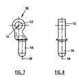
- Fig. 7 eine Seitenansicht des Verbindungsteils;
- Fig. 8 eine Ansicht des Verbindungsteils in Richtung des Pfeiles A;
- Fig. 9, 10, 11 eine schematische Darstellung einer Beugebewegung des Femurteils in verschieden stark gebeugter Position;
- Fig. 12 eine von dorsal gesehene Ansicht des die Kondylen enthaltenden unteren Abschnitts eines Femurknochens; und
- Fig. 13 eine Seitenansicht des unteren Abschnitts des Femurknochens gemäß Fig. 12.
- 1 shows a cross section through the knee joint endoprosthesis from the side,
- FIG. 2 is a ventral view of the tibia part of the endoprosthesis according to FIG. 1;
- 3 shows a plan view of the tibia part according to FIG. 2;
- FIG. 4 shows an enlarged side view of the femoral part of the endoprosthesis according to FIG. 1;
- 5 shows a cross section along the line VV through the femoral part of FIG. 4.
- 6 shows a cross section along the line VI-VI through the femoral part according to FIG. 4;
- Fig. 7 is a side view of the connecting part;
- 8 is a view of the connecting part in the direction of arrow A;
- 9, 10, 11 show a schematic illustration of a flexion movement of the femoral part in a differently flexed position;
- 12 is a dorsal view of the lower portion of the femur containing the condyles; and
- 13 is a side view of the lower section of the femur according to FIG. 12.
Die Kniegelenk-Endoprothese gemäß Fig. 1 besteht aus einem Femurteil 2, welches einen Schaft 14 zur Verankerung im Knochenhohlraum des menschlichen Femurknochens besitzt. Am unteren Ende des Schafts 14 sind zwei konvex gekrümmte, relativ dünnwandige Kondylenschalen 4 angeordnet, die bei einer Implantation des Femurteils 2 die Kondylen des natürlichen Femurknochen umfassen sollen.The knee joint endoprosthesis according to FIG. 1 consists of a
Das Femurteil 2 stützt sich über die Kondylenschalen 4 auf einem Tibiateil 20, welches ein Tibiaplateau 24, und einen Einsatz 36 auf dem Tibiaplateau 24 aufweist. Der Tibiaplateau-Einsatz 36 besitzt unterhalb der Kondylenschalen 4 je eine entsprechend konkav gekrümmte Stützfläche 38 eingeformt, zwischen den Stützflächen 38 verläuft in ventral-dorsaler Richtung ein Höcker 40, der sich in einem unter dem Schaft 14 verlaufenden Zwischenraum 12 zwischen den Kondylenschalen 4 erstreckt, vgl. auch die Fig. 5 und 6, und als Anschlag für eine Rotationsbewegung des Femurteil 2 relativ zum Tibiateil 20 dient. An der Unterseite des Tibiaplateaus 24 befindet sich ein Schaft 22, der geringfügig angewinkelt vom Tibiaplateau 24 nach unten absteht und zur Verankerung des Tibiateils im Knochenhohlraum des natürlichen Tibiaknochens dient.The
Das Femurteil 2 ist mit einem Verbindungsteil 50 mit dem Tibiateil 20 so gekoppelt, daß das Femurteil 2 eine Beuge- oder Schwenkbewegung auf dem Tibiaplateau 24 um eine - in Darstellung - horizontale Achse, und außerdem eine Rotationsbewegung um eine - in der Darstellung - im wesentlichen vertikale Achse ausführen kann. Am oberen Ende des Verbindungsteils 50 ist zu diesem Zweck ein Auge 52 angeformt, welches in den Zwischenraum 12 zwischen den Kondylenschalen 4 hineinragt und mittels eines Querbolzens 60 schwenkbar mit dem Femurteil 2 verbunden ist. Der Querbolzen 60 ist in Bohrungen 10 der beiden Seitenwände 8 gelagert, welche in vorgegebenem Abstand einander gegenüber liegen und zwischen sich den Zwischenraum 12 bilden, in dem das Verbindungsteil 50 auf dem Querbolzen 60 lagert. Das untere Ende des Verbindungsteils 50 ist als Zapfen 56 ausgebildet, der quer zur Schwenkachse verläuft, die mit der Achse 54 des Querbolzens 60 zusammenfällt. Der Zapfen 56 lagert in einer Bohrung 30, die senkrecht zur Ebene des Tibiaplateaus von oben in das Tibiaplateau in Richtung des Schafts 22 eingearbeitet ist.The
Der Zapfen 56 des Verbindungsteils 50 ist im Tibiateil 20 anschlagfrei axial verschiebbar gelagert, so daß sich das Verbindungsteil 50 bei einer Beugebewegung des Femurteils 2 aus der Bohrung 30 heraus bzw. in die Bohrung hinein verschieben läßt.The
Die den Stützflächen 38 des Tibiaplateau-Einsatzes 36 zugewandten Abschnitte der Kondylenschalen 4 sind einer Rotationsfläche um eine Kondylenschalenachse 6 angenähert, sie sind im dargestellten Ausführungsbeispiel Teil einer Kreiszylinder-Oberfläche, dessen Zylinderachse die Kondylenschalenachse 6 darstellt, die parallel zur Achse 62 des Querbolzens 6 verläuft und gegen die Achse 62 des Querbolzens 60 einen vorge gebenen Versatz a nach oben und ggf. auch geringfügig nach ventral besitzt.The sections of the
Wie sich insbesondere den Fig. 4 bis 6 entnehmen läßt, ist der Abstand a der Kondylenschalenachse 6 von der Achse 62 des Querbolzens 60 in der dargestellten Ausführungsform kleiner als der halbe Durchmesser d des Querbolzens. Die Kondylenschalenachse 6 weist gegenüber einer Referenzebene 16, die durch die Achse 62 des Querbolzens und im wesentlichen senkrecht zu der Verbindungslinie von ventraler und dorsaler Endkante der Kondylenschalen 4 verläuft einen geringen Versatz b nach ventral.As can be seen in particular from FIGS. 4 to 6, the distance a of the
Wie insbesondere in Fig. 1 bis 3 entnehmbar ist, ist das Tibiaplateau 24 des Tibiateils 20 gegen den Tibiaschaft 22 in dorsal-ventraler Richtung geneigt und steigt - gegenüber einer lotrecht auf dem Schaft 23 sitzenden Referenzebene nach ventral um 3 bis 10°, besonders bevorzugt um 4 bis 6° an. Die Bohrung 30 des Tibiateils 20 verläuft senkrecht zur Ebene des Tibiaplateaus 24 und ist gegen die Achse 23 des Tibiaschaftes 22 versetzt.As can be seen in particular in FIGS. 1 to 3, the
Wie insbesondere Fig. 3 entnehmbar ist, ist die Achse 32 der Bohrung 30 in der Ebene des Tibiaplateaus 24 gegen die Achse 23 des Tibiaschafts 22 nach medial um einen Abstand m, und nach dorsal um einen Abstand n versetzt. Der Tibiaschaft besitzt - von ventral gesehen - außerdem eine geringfügige Neigung nach medial. Der Winkel β , den der Tibiaschaft nach medial mit dem Tibiaplateau 24 bildet, beträgt zwischen 84 bis 88°. Durch diese Anwinkelung des Tibiaschaftes 22 wird erreicht, daß das Tibiaplateau 24 bei normaler Stand position eines Patienten auch in der lateral-medialen Richtung horizontal verläuft.As can be seen in particular in FIG. 3, the
Wie den Fig. 1 bis 3 entnehmbar ist, besitzt das Tibiaplateau 24 einen umlaufenden Randwulst 26 sowie einen um die Bohrung 30 umlaufenden Randsteg 28 zur sicheren Einfassung des Tibiaplateau-Einsatzes 36.As can be seen in FIGS. 1 to 3, the
Wie insbesondere Fig. 3 entnehmbar ist, ist die mediale Stützfläche 38a des Tibiaplateau-Einsatzes 36 größer und erstreckt sich weiter nach dorsal als die laterale Stützfläche 38b.3, the medial support surface 38a of the
Die Fig. 4 bis 6 zeigen eine vergrößerte Seitenansicht und Schnitte des Femurteils 2. Gemäß Fig. 4 besitzen die Kondylenschalen 4 ventral einen Abschnitt 18 mit kleinerer Krümmung, um eine bessere Anpassung an die Form der natürlichen Kondylen zu verwirklichen. Der Schaft 14 des Femurteils ist - in ventral-dorsaler Richtung - etwa symmetrisch über dem Querbolzen 60 angesetzt, der das Verbindungsteil 50 im Zwischenraum 12 schwenkbar hält. Der Schaft 14 ist nach dorsal geneigt und/oder gekrümmt, um beim Implantieren ein einfaches Einsetzen des Femurteils von dorsal in eine Bohrung zwischen den Kondylen zu ermöglichen.4 to 6 show an enlarged side view and sections of the
Die Fig. 7 und 8 zeigen das Verbindungsteil 50 in Seitenansicht und in Frontansicht. Wie Fig. 7 entnehmbar ist, ist die Achse 58 des Zapfens 56 gegenüber der Achse 54 des Auges 52 durch welches der Querbolzen 60 verläuft, um einen Versatz v nach ventral versetzt. Dadurch kommt die Querbolzenachse 62 gegenüber der Bohrung 30 des Tibiateils um den Versatz v nach dorsal zu liegen und nimmt dann eine der natürlichen Beugeachse entsprechende Position ein.7 and 8 show the connecting
In den Fig. 9 bis 11 ist die Beugebewegung des Femurteils 2 mit verschiedenen Beugewinkeln dargestellt, der Einfachheit halber sind jedoch die Kondylenschalen als 180°-Abschnitt einer Kreiszylinderfläche gezeichnet. Die Kondylenschalenachse 6 verläuft - wie bei der erfindungsgemäßen Kniegelenk-Endoprothese - um einen vorgegebenen Versatz a über der Achse 62 des Querbolzens 60, der einen Durchmesser d besitzt. Der Durchmesser des die Kondylenschalen bildenden Kreiszylinder-Abschnitts ist mit D bezeichnet.9 to 11 show the flexion movement of the
Fig. 9 zeigt das Femurteil 2 in einer relativ stark gebeugten oder abgewinkelten Stellung des Kniegelenks, bei der die Kondylenschalenachse 6 lotrecht über der Achse 62 des Querbolzens 60 liegt, so daß die Kondylenschalen den Tibiaplateau-Einsatz 36 ebenfalls lotrecht unter der Querbolzenachse 62 berühren.Fig. 9 shows the
Wenn der Beugewinkel abnimmt, das Femurteil 2 sich also der Strecklage stärker annähert, vgl. Fig. 10, so wird die Kondylenschalenachse 6 dabei um die Querbolzenachse 62 nach ventral geschwenkt; der Berührungspunkt zwischen Kondylenschalen und Tibiaplateau-Einsatz liegt - wie bei einem abrollenden Kreiszylinder - stets lotrecht unter der Kondylenschalenachse 6, d. h. der Berührungspunkt zwischen Femurteil und Tibiateil "rollt" bei diesem Bewegungsablauf mit zunehmendem Übergang in die Strecklage - nach ventral. Bei vollständiger Streckung, vgl. Fig. 11, liegt der Berührungspunkt zwischen Femurteil und Tibiateil um den Versatz a ventral vor der Querbolzenachse 62. Mit zu nehmendem Übergang in die Strecklage wandert daher der Berührungspunkt zwischen Femurteil und Tibiateil nach ventral, auf diese Weise wird die Abroll-Bewegungskomponente der Kniegelenk-Endoprothese realisiert.If the flexion angle decreases, the
Die Implantation der Kniegelenk-Endoprothese ist außerordentlich gewebeschonend und beläßt im Gegensatz zu bisher bekannten Prothesen die wesentlichen Teile des Femurs bzw. dessen Kondylen ohne Schwächung. Da die Endoprothese keinen breiten femuralen Block besitzt, der im natürlichen Femurgewebe verankert werden muß und folglich ein entsprechend großes interkondyläres Fenster erfordert, ist die Resektion eines entsprechend großen Knochengewebeteils nicht notwendig. Vielmehr wird bei der erfindungsgemäße Endoprothese lediglich zwischen den natürlichen Kondylen 70, 72 - vgl. die Fig. 12 und 13 - an einer Stelle, wo ohnehin kein tragendes Knochengewebe vorhanden ist, nämlich bei den Kreuzbändern, eine dem Femurschaft 14 bzw. dessen Durchmessers entsprechende Bohrung 74 angebracht, wie sie in Fig. 12 mit einer strichpunktierten Elypse angedeutet und kreuzschraffiert dargestellt ist, und die Prothese wird sodann mit dem freien Endabschnitt des gekrümmten Femurschaftes 14 voran in Richtung der Pfeil-Strichlinie 76, vgl. Fig. 13, in die Bohrung 74 eingebracht. Aufgrund der Krümmung des Femurschaftes 14 läßt sich dieser ohne Schwierigkeiten durch die Bohrung 74 in den Markkanal des Femurs 3 einbringen.The implantation of the knee joint endoprosthesis is extremely gentle on the tissue and, in contrast to previously known prostheses, leaves the essential parts of the femur or its condyles without weakening. Since the endoprosthesis does not have a wide femoral block that has to be anchored in the natural femoral tissue and consequently requires a correspondingly large intercondylar window, the resection of a correspondingly large part of the bone tissue is not necessary. Rather, in the endoprosthesis according to the invention, only between the
Besonders bevorzugt besitzt der Tibiaplateau-Einsatz 36 auch im dorsalen Bereich zwischen den beiden Stützflächen 38a und 38b einen Höcker zur Begrenzung der Rotationsbewegung.Particularly preferably, the
Claims (15)
mit einem Einsatz (36) auf dem Tibiaplateau mit entsprechend konkav gekrümmten Stützflächen (38) für die Kondylenschalen (4),
mit einem Verbindungsteil (50), welches mit einem Ende in einen Zwischenraum (12) zwischen den Kondylenschalen (4) hineinragt, mittels eines Querbolzens (60) schwenkbar mit dem Femurteil (2) verbunden ist und mit einem Zapfen (56) drehbar in einer Bohrung (30) des Tibiateils (20) lagert,
dadurch gekennzeichnet, daß der Zapfen (56) des Verbindungsteils (50) anschlagfrei axial verschiebbar gelagert ist, und daß die Kondylenschalen (4) einer Rotationsfläche um eine Kondylenschalenachse (6) angenähert sind, die oberhalb und parallel zur Achse (62) des Querbolzens (60) verläuft.1. knee joint endoprosthesis, the femoral part (2) of which at the lower end of a shaft (14) has a convexly curved condyle shell (4), and the tibia part (20) of which has a tibial plateau (24) at the upper end of a shaft (22),
with an insert (36) on the tibia plateau with correspondingly concave support surfaces (38) for the condyle shells (4),
with a connecting part (50), which protrudes at one end into a space (12) between the condyle shells (4), is pivotally connected to the femur part (2) by means of a cross bolt (60) and rotatable in one with a pin (56) Bore (30) of the tibia part (20) is supported,
characterized in that the pin (56) of the connecting part (50) is axially displaceably mounted without a stop, and in that the condyle shells (4) are approximated to a surface of revolution about a condyle shell axis (6) which is above and parallel to the axis (62) of the transverse bolt ( 60) runs.
dadurch gekennzeichnet, daß der Abstand (a) der Kondylenschalenachse (6) von der Achse (62) des Querbolzens (60) kleiner ist als der Durchmesser (d) des Querbolzens (60).2. knee joint endoprosthesis according to claim 1,
characterized in that the distance (a) of the condyle shell axis (6) from the axis (62) of the transverse bolt (60) is smaller than the diameter (d) of the transverse bolt (60).
dadurch gekennzeichnet, daß der Abstand (a) der Kondy lenschalenachse (6) von der Achse (62) des Querbolzens (60) kleiner ist als der halbe Durchmesser (d) des Querbolzens (60).3. knee joint endoprosthesis according to claim 2,
characterized in that the distance (a) of the Kondy lenschalenachse (6) of the axis (62) of the cross bolt (60) is smaller than half the diameter (d) of the cross bolt (60).
dadurch gekennzeichnet, daß das Tibiaplateau (24) gegen den Tibiaschaft (22) in dorsal-ventaler Richtung geneigt ist und nach ventral um 3 bis 10° ansteigt.4. knee joint endoprosthesis according to claim 1 or 2,
characterized in that the tibial plateau (24) is inclined towards the tibial shaft (22) in the dorsal-vental direction and rises ventrally by 3 to 10 °.
dadurch gekennzeichnet, daß die Bohrung (30) senkrecht zur Ebene des Tibiaplateaus (24) von oben in das Tibiateil (20) hinein verläuft.5. knee joint endoprosthesis according to one of the preceding claims,
characterized in that the bore (30) extends perpendicularly to the plane of the tibia plateau (24) from above into the tibia part (20).
dadurch gekennzeichnet, daß die Bohrung (30) des Tibiateils (20) in der Ebene des Tibiaplateaus (24) gegen den Tibiaschaft (22) einen vorgegebenen Achsversatz aufweist.6. knee joint endoprosthesis according to one of the preceding claims,
characterized in that the bore (30) of the tibia part (20) has a predetermined axial offset in the plane of the tibia plateau (24) against the tibia shaft (22).
dadurch gekennzeichnet, daß die Achse (32) der Bohrung (30) des Tibiateils (20) in der Ebene des Tibiaplateaus (24) gegen die Achse (23) des Tibiaschafts (22) nach medial und/oder dorsal versetzt ist.7. knee joint endoprosthesis according to claim 5,
characterized in that the axis (32) of the bore (30) of the tibia part (20) in the plane of the tibia plateau (24) is offset medially and / or dorsally against the axis (23) of the tibia shaft (22).
dadurch gekennzeichnet, daß die den Stützflächen (38) des Tibiaplateau-Einsatzes (36) zugewandten Abschnitte der Kondylenschalen (4) als Rotationsfläche einen Kreiszylinder-Abschnitt bilden.8. knee joint endoprosthesis according to one of the preceding claims,
characterized in that the sections of the condyle shells (4) facing the support surfaces (38) of the tibial plateau insert (36) form a circular cylinder section as the surface of rotation.
dadurch gekennzeichnet, daß die Kondylenschalen (4) ventral in einen Abschnitt (18) mit kleinerer Krümmung übergehen.9. knee joint endoprosthesis according to one of the preceding claims,
characterized in that the condyle shells (4) merge ventrally into a section (18) with a smaller curvature.
dadurch gekennzeichnet, daß der Tibiaschaft (22) zu seinem freien Ende hin geringfügig nach medial geneigt verläuft.10. knee joint endoprosthesis according to one of the preceding claims,
characterized in that the tibia shaft (22) extends slightly towards the medial towards its free end.
dadurch gekennzeichnet, daß der Winkel (β), den der Tibiaschaft (22) in medialer Richtung mit dem Tibiaplateau (24) bildet, etwa 84° bis 88° beträgt.11. knee joint endoprosthesis according to claim 9,
characterized in that the angle (β) which the tibial shaft (22) forms in the medial direction with the tibial plateau (24) is approximately 84 ° to 88 °.
dadurch gekennzeichnet, daß die mediale Stützfläche (38a) des Tibiaplateau-Einsatzes (36) sich weiter nach dorsal erstreckt als die laterale Stützfläche (38b).12. Knee joint endoprosthesis according to one of the preceding claims,
characterized in that the medial support surface (38a) of the tibial plateau insert (36) extends further dorsally than the lateral support surface (38b).
dadurch gekennzeichnet, daß der Schaft (14) des Femurteils (2) nach dorsal geneigt und/oder gekrümmt verläuft.13. Knee joint endoprosthesis according to one of the preceding claims,
characterized in that the shaft (14) of the femoral part (2) is inclined dorsally and / or curved.
dadurch gekennzeichnet, daß der Schaft (14) des Femurteils (2) in ventral-dorsaler Richtung etwa symmetrisch über dem Querbolzen (60) ansetzt.14. Knee joint endoprosthesis according to one of the preceding claims,
characterized in that the shaft (14) of the femoral part (2) attaches approximately symmetrically above the transverse bolt (60) in the ventral-dorsal direction.
dadurch gekennzeichnet, daß die Achse (58) des Zapfens (56) des Verbindungsteils (50) gegenüber der Achse (54) des Auges (52) durch mehrere der Querbolzen (60) verläuft, um einen Versatz v nach ventral versetzt ist.15. Knee joint endoprosthesis according to one of the preceding claims,
characterized in that the axis (58) of the pin (56) of the connecting part (50) with respect to the axis (54) of the eye (52) extends through a plurality of the transverse bolts (60) by an offset v to the ventral position.
Priority Applications (1)
| Application Number | Priority Date | Filing Date | Title |
|---|---|---|---|
| AT90113502T ATE96996T1 (en) | 1989-07-26 | 1990-07-14 | KNEE ARDOPROSTHESIS. |
Applications Claiming Priority (4)
| Application Number | Priority Date | Filing Date | Title |
|---|---|---|---|
| DE8909036U | 1989-07-26 | ||
| DE8909036U DE8909036U1 (en) | 1989-07-26 | 1989-07-26 | |
| DE4002424 | 1990-01-27 | ||
| DE4002424A DE4002424A1 (en) | 1989-07-26 | 1990-01-27 | Knee joint prosthesis with femur shells and tibia plate - has lug on connecting component sliding freely in axial direction |
Publications (2)
| Publication Number | Publication Date |
|---|---|
| EP0410237A1 true EP0410237A1 (en) | 1991-01-30 |
| EP0410237B1 EP0410237B1 (en) | 1993-11-10 |
Family
ID=25889466
Family Applications (1)
| Application Number | Title | Priority Date | Filing Date |
|---|---|---|---|
| EP90113502A Expired - Lifetime EP0410237B1 (en) | 1989-07-26 | 1990-07-14 | Knee joint endoprosthesis |
Country Status (5)
| Country | Link |
|---|---|
| EP (1) | EP0410237B1 (en) |
| AT (1) | ATE96996T1 (en) |
| DE (2) | DE4002424A1 (en) |
| DK (1) | DK0410237T3 (en) |
| ES (1) | ES2046606T3 (en) |
Cited By (8)
| Publication number | Priority date | Publication date | Assignee | Title |
|---|---|---|---|---|
| FR2692475A1 (en) * | 1992-06-19 | 1993-12-24 | Montpellier Chirurgie | Total knee replacement. |
| FR2707871A1 (en) * | 1993-07-22 | 1995-01-27 | Serf | Bicondylar knee prosthesis of the sliding type |
| DE19618321C2 (en) * | 1996-02-21 | 2001-03-08 | Plus Endoprothetik Ag Rotkreuz | Knee joint endoprosthesis |
| US6485519B2 (en) | 2001-01-29 | 2002-11-26 | Bristol-Myers Squibb Company | Constrained prosthetic knee with rotating bearing |
| EP1269938A1 (en) * | 2001-06-27 | 2003-01-02 | Waldemar Link (GmbH & Co.) | Coupled knee prothesis with rotational bearing |
| US6719800B2 (en) | 2001-01-29 | 2004-04-13 | Zimmer Technology, Inc. | Constrained prosthetic knee with rotating bearing |
| US6773461B2 (en) | 2001-01-29 | 2004-08-10 | Zimmer Technology, Inc. | Constrained prosthetic knee with rotating bearing |
| EP3666229A1 (en) * | 2018-12-10 | 2020-06-17 | Waldemar Link GmbH & Co. KG | Knee joint endoprosthetic set and instruments |
Families Citing this family (2)
| Publication number | Priority date | Publication date | Assignee | Title |
|---|---|---|---|---|
| DE4110048C1 (en) * | 1991-03-27 | 1992-07-30 | S + G Implants Gmbh, 2400 Luebeck, De | Knee joint prosthesis with femur and tibia portions - has femur condylar shells recessed on ventral side towards shell inside |
| DE19626438B4 (en) * | 1996-06-19 | 2007-03-22 | Implantcast Gmbh | knee prosthesis |
Citations (5)
| Publication number | Priority date | Publication date | Assignee | Title |
|---|---|---|---|---|
| FR2330375A1 (en) * | 1975-11-04 | 1977-06-03 | Dadurian Aram | KNEE PROSTHESIS |
| DE2802568A1 (en) * | 1978-01-21 | 1979-07-26 | Omar Pacha Nabil Dr | Implanted artificial knee joint - has hinged connection between upper and lower parts, with provision for limited axial rotation |
| US4301553A (en) * | 1975-08-15 | 1981-11-24 | United States Surgical Corporation | Prosthetic knee joint |
| GB2129306A (en) * | 1982-11-04 | 1984-05-16 | Howmedica | Joint prosthesis |
| DE3529894A1 (en) * | 1985-08-21 | 1987-03-05 | Orthoplant Endoprothetik | Knee-joint endoprosthesis |
Family Cites Families (3)
| Publication number | Priority date | Publication date | Assignee | Title |
|---|---|---|---|---|
| DE7634751U1 (en) * | 1976-11-02 | 1977-05-05 | Omar-Pacha, Nabil, Dr.Dr., 3470 Hoexter | Knee joint prosthesis |
| DE2744710A1 (en) * | 1977-10-05 | 1979-04-19 | Heldt Gert Dipl Ing Dr | ENDOPROSTHESIS OF A KNEE JOINT |
| DE3431645A1 (en) * | 1984-08-29 | 1986-03-13 | GMT GESELLSCHAFT FüR MEDIZINISCHE TECHNIK MBH | ENDOPROTHESIS |
-
1990
- 1990-01-27 DE DE4002424A patent/DE4002424A1/en active Granted
- 1990-07-14 ES ES199090113502T patent/ES2046606T3/en not_active Expired - Lifetime
- 1990-07-14 DK DK90113502.0T patent/DK0410237T3/en active
- 1990-07-14 AT AT90113502T patent/ATE96996T1/en active
- 1990-07-14 DE DE90113502T patent/DE59003425D1/en not_active Expired - Fee Related
- 1990-07-14 EP EP90113502A patent/EP0410237B1/en not_active Expired - Lifetime
Patent Citations (5)
| Publication number | Priority date | Publication date | Assignee | Title |
|---|---|---|---|---|
| US4301553A (en) * | 1975-08-15 | 1981-11-24 | United States Surgical Corporation | Prosthetic knee joint |
| FR2330375A1 (en) * | 1975-11-04 | 1977-06-03 | Dadurian Aram | KNEE PROSTHESIS |
| DE2802568A1 (en) * | 1978-01-21 | 1979-07-26 | Omar Pacha Nabil Dr | Implanted artificial knee joint - has hinged connection between upper and lower parts, with provision for limited axial rotation |
| GB2129306A (en) * | 1982-11-04 | 1984-05-16 | Howmedica | Joint prosthesis |
| DE3529894A1 (en) * | 1985-08-21 | 1987-03-05 | Orthoplant Endoprothetik | Knee-joint endoprosthesis |
Cited By (21)
| Publication number | Priority date | Publication date | Assignee | Title |
|---|---|---|---|---|
| WO1994000081A1 (en) * | 1992-06-19 | 1994-01-06 | Montpellier Chirurgie | Total knee prosthesis |
| FR2692475A1 (en) * | 1992-06-19 | 1993-12-24 | Montpellier Chirurgie | Total knee replacement. |
| CN1107488C (en) * | 1992-06-19 | 2003-05-07 | 佩梅迪卡股份公司 | Artificial knee joint |
| FR2707871A1 (en) * | 1993-07-22 | 1995-01-27 | Serf | Bicondylar knee prosthesis of the sliding type |
| DE19618321C2 (en) * | 1996-02-21 | 2001-03-08 | Plus Endoprothetik Ag Rotkreuz | Knee joint endoprosthesis |
| US8268006B2 (en) | 2001-01-29 | 2012-09-18 | Zimmer, Inc. | Constrained prosthetic knee with rotating bearing |
| US6485519B2 (en) | 2001-01-29 | 2002-11-26 | Bristol-Myers Squibb Company | Constrained prosthetic knee with rotating bearing |
| US8888857B2 (en) | 2001-01-29 | 2014-11-18 | Zimmer, Inc. | Constrained prosthetic knee with rotating bearing |
| USRE44476E1 (en) | 2001-01-29 | 2013-09-03 | Zimmer, Inc. | Constrained prosthetic knee with rotating bearing |
| US6719800B2 (en) | 2001-01-29 | 2004-04-13 | Zimmer Technology, Inc. | Constrained prosthetic knee with rotating bearing |
| US6773461B2 (en) | 2001-01-29 | 2004-08-10 | Zimmer Technology, Inc. | Constrained prosthetic knee with rotating bearing |
| EP1269938A1 (en) * | 2001-06-27 | 2003-01-02 | Waldemar Link (GmbH & Co.) | Coupled knee prothesis with rotational bearing |
| US7303586B2 (en) | 2001-06-27 | 2007-12-04 | Waldermar Link Gmbh & Co. Kg | Coupled knee prosthesis with a rotational bearing |
| KR100879834B1 (en) * | 2001-06-27 | 2009-01-22 | 발데마르 링크 게엠베하 운트 코.카게 | Coupled knee prosthesis with a rotational bearing |
| AU2002352622B2 (en) * | 2001-06-27 | 2006-11-16 | Waldemar Link Gmbh & Co. Kg | Coupled knee prosthesis with a rotational bearing |
| CZ303635B6 (en) * | 2001-06-27 | 2013-01-23 | Waldemar Link Gmbh & Co. Kg | Interconnected knee prosthesis with rotational bearing |
| WO2003002039A3 (en) * | 2001-06-27 | 2003-05-01 | Link Waldemar Gmbh Co | Coupled knee prosthesis with a rotational bearing |
| WO2003002039A2 (en) * | 2001-06-27 | 2003-01-09 | Waldemar Link Gmbh & Co. Kg | Coupled knee prosthesis with a rotational bearing |
| EP3666229A1 (en) * | 2018-12-10 | 2020-06-17 | Waldemar Link GmbH & Co. KG | Knee joint endoprosthetic set and instruments |
| WO2020120475A1 (en) * | 2018-12-10 | 2020-06-18 | Waldemar Link Gmbh & Co. Kg | Knee joint endoprosthesis set and instruments |
| CN113164261A (en) * | 2018-12-10 | 2021-07-23 | 沃尔德马连接两合公司 | Knee joint endoprosthesis kit and instrument assembly |
Also Published As
| Publication number | Publication date |
|---|---|
| DE4002424A1 (en) | 1991-02-07 |
| DK0410237T3 (en) | 1993-12-20 |
| DE59003425D1 (en) | 1993-12-16 |
| ES2046606T3 (en) | 1994-02-01 |
| DE4002424C2 (en) | 1991-09-12 |
| ATE96996T1 (en) | 1993-11-15 |
| EP0410237B1 (en) | 1993-11-10 |
Similar Documents
| Publication | Publication Date | Title |
|---|---|---|
| DE602005002293T2 (en) | knee prosthesis | |
| EP0791344B1 (en) | Knee joint endoprosthesis | |
| DE60023953T2 (en) | BENDING PROPERTIES WITH MOVABLE BEARING AND FIXED TIBIAL STEM | |
| DE60128503T2 (en) | Posterior stabilized knee replacement with features to prevent dislocation | |
| EP0539654B1 (en) | System of a knee joint endoprosthesis | |
| DE60125620T2 (en) | Posterior stabilized knee replacement for knees with preserved lateral ligaments | |
| DE60302323T2 (en) | Movable talar part for total ankle prosthesis | |
| DE69936085T2 (en) | Knee with stabilized, movable bearing | |
| DE19606462C1 (en) | Knee joint endoprosthesis | |
| EP2438889B1 (en) | Knee joint prosthesis | |
| DE19647155C2 (en) | Implant | |
| DE2933124C2 (en) | Endoprosthesis for a knee joint | |
| DE2230734B2 (en) | Endoprosthesis for a human knee or elbow joint and process for their manufacture | |
| DE2452412C3 (en) | Total endoprosthesis for knee joints | |
| DE2906458A1 (en) | JOINT PROSTHESIS | |
| EP2475333B1 (en) | Knee joint endoprosthesis | |
| DE2505322B2 (en) | Knee joint endoprosthesis | |
| DE3529894A1 (en) | Knee-joint endoprosthesis | |
| DE19529824A1 (en) | Bi-condylar endoprosthesis for knee | |
| EP0194326B1 (en) | Knee-joint endoprosthesis | |
| EP1226799B1 (en) | Inlay for a knee endoprosthesis | |
| EP0410237B1 (en) | Knee joint endoprosthesis | |
| DE10012059C2 (en) | Endoprosthesis for a knee joint | |
| DE3022668C2 (en) | Knee joint slide endoprosthesis | |
| EP0955020B1 (en) | Assembly set for knee prostheses |
Legal Events
| Date | Code | Title | Description |
|---|---|---|---|
| PUAI | Public reference made under article 153(3) epc to a published international application that has entered the european phase |
Free format text: ORIGINAL CODE: 0009012 |
|
| AK | Designated contracting states |
Kind code of ref document: A1 Designated state(s): AT BE CH DE DK ES FR GB GR IT LI LU NL SE |
|
| 17P | Request for examination filed |
Effective date: 19910718 |
|
| 17Q | First examination report despatched |
Effective date: 19921021 |
|
| GRAA | (expected) grant |
Free format text: ORIGINAL CODE: 0009210 |
|
| AK | Designated contracting states |
Kind code of ref document: B1 Designated state(s): AT BE CH DE DK ES FR GB GR IT LI LU NL SE |
|
| PG25 | Lapsed in a contracting state [announced via postgrant information from national office to epo] |
Ref country code: GR Free format text: LAPSE BECAUSE OF FAILURE TO SUBMIT A TRANSLATION OF THE DESCRIPTION OR TO PAY THE FEE WITHIN THE PRESCRIBED TIME-LIMIT Effective date: 19931110 |
|
| REF | Corresponds to: |
Ref document number: 96996 Country of ref document: AT Date of ref document: 19931115 Kind code of ref document: T |
|
| ITF | It: translation for a ep patent filed |
Owner name: JACOBACCI CASETTA & PERANI S.P.A. |
|
| GBT | Gb: translation of ep patent filed (gb section 77(6)(a)/1977) |
Effective date: 19931111 |
|
| REF | Corresponds to: |
Ref document number: 59003425 Country of ref document: DE Date of ref document: 19931216 |
|
| REG | Reference to a national code |
Ref country code: DK Ref legal event code: T3 |
|
| REG | Reference to a national code |
Ref country code: ES Ref legal event code: FG2A Ref document number: 2046606 Country of ref document: ES Kind code of ref document: T3 |
|
| ET | Fr: translation filed | ||
| PG25 | Lapsed in a contracting state [announced via postgrant information from national office to epo] |
Ref country code: AT Effective date: 19940714 |
|
| PG25 | Lapsed in a contracting state [announced via postgrant information from national office to epo] |
Ref country code: LU Free format text: LAPSE BECAUSE OF NON-PAYMENT OF DUE FEES Effective date: 19940731 Ref country code: LI Effective date: 19940731 Ref country code: CH Effective date: 19940731 |
|
| PLBE | No opposition filed within time limit |
Free format text: ORIGINAL CODE: 0009261 |
|
| STAA | Information on the status of an ep patent application or granted ep patent |
Free format text: STATUS: NO OPPOSITION FILED WITHIN TIME LIMIT |
|
| 26N | No opposition filed | ||
| EAL | Se: european patent in force in sweden |
Ref document number: 90113502.0 |
|
| REG | Reference to a national code |
Ref country code: CH Ref legal event code: PL |
|
| PGFP | Annual fee paid to national office [announced via postgrant information from national office to epo] |
Ref country code: FR Payment date: 19960617 Year of fee payment: 7 |
|
| PGFP | Annual fee paid to national office [announced via postgrant information from national office to epo] |
Ref country code: GB Payment date: 19960709 Year of fee payment: 7 |
|
| PGFP | Annual fee paid to national office [announced via postgrant information from national office to epo] |
Ref country code: SE Payment date: 19960719 Year of fee payment: 7 |
|
| PGFP | Annual fee paid to national office [announced via postgrant information from national office to epo] |
Ref country code: DK Payment date: 19960722 Year of fee payment: 7 |
|
| PGFP | Annual fee paid to national office [announced via postgrant information from national office to epo] |
Ref country code: BE Payment date: 19960723 Year of fee payment: 7 |
|
| PGFP | Annual fee paid to national office [announced via postgrant information from national office to epo] |
Ref country code: ES Payment date: 19960729 Year of fee payment: 7 |
|
| PGFP | Annual fee paid to national office [announced via postgrant information from national office to epo] |
Ref country code: NL Payment date: 19960730 Year of fee payment: 7 |
|
| PG25 | Lapsed in a contracting state [announced via postgrant information from national office to epo] |
Ref country code: GB Free format text: LAPSE BECAUSE OF NON-PAYMENT OF DUE FEES Effective date: 19970714 Ref country code: DK Free format text: LAPSE BECAUSE OF NON-PAYMENT OF DUE FEES Effective date: 19970714 |
|
| REG | Reference to a national code |
Ref country code: DK Ref legal event code: EBP |
|
| PG25 | Lapsed in a contracting state [announced via postgrant information from national office to epo] |
Ref country code: SE Effective date: 19970715 Ref country code: ES Free format text: LAPSE BECAUSE OF THE APPLICANT RENOUNCES Effective date: 19970715 |
|
| PG25 | Lapsed in a contracting state [announced via postgrant information from national office to epo] |
Ref country code: BE Free format text: LAPSE BECAUSE OF NON-PAYMENT OF DUE FEES Effective date: 19970731 |
|
| BERE | Be: lapsed |
Owner name: BRISTOL-MYERS SQUIBB CY Effective date: 19970731 |
|
| PG25 | Lapsed in a contracting state [announced via postgrant information from national office to epo] |
Ref country code: NL Free format text: LAPSE BECAUSE OF NON-PAYMENT OF DUE FEES Effective date: 19980201 |
|
| GBPC | Gb: european patent ceased through non-payment of renewal fee |
Effective date: 19970714 |
|
| PG25 | Lapsed in a contracting state [announced via postgrant information from national office to epo] |
Ref country code: FR Free format text: LAPSE BECAUSE OF NON-PAYMENT OF DUE FEES Effective date: 19980331 |
|
| NLV4 | Nl: lapsed or anulled due to non-payment of the annual fee |
Effective date: 19980201 |
|
| EUG | Se: european patent has lapsed |
Ref document number: 90113502.0 |
|
| REG | Reference to a national code |
Ref country code: FR Ref legal event code: ST |
|
| PGFP | Annual fee paid to national office [announced via postgrant information from national office to epo] |
Ref country code: DE Payment date: 20000728 Year of fee payment: 11 |
|
| REG | Reference to a national code |
Ref country code: ES Ref legal event code: FD2A Effective date: 20001102 |
|
| PG25 | Lapsed in a contracting state [announced via postgrant information from national office to epo] |
Ref country code: DE Free format text: LAPSE BECAUSE OF NON-PAYMENT OF DUE FEES Effective date: 20020501 |
|
| PG25 | Lapsed in a contracting state [announced via postgrant information from national office to epo] |
Ref country code: IT Free format text: LAPSE BECAUSE OF NON-PAYMENT OF DUE FEES;WARNING: LAPSES OF ITALIAN PATENTS WITH EFFECTIVE DATE BEFORE 2007 MAY HAVE OCCURRED AT ANY TIME BEFORE 2007. THE CORRECT EFFECTIVE DATE MAY BE DIFFERENT FROM THE ONE RECORDED. Effective date: 20050714 |