EP0411121A1 - Optical thermometer - Google Patents
Optical thermometer Download PDFInfo
- Publication number
- EP0411121A1 EP0411121A1 EP89900877A EP89900877A EP0411121A1 EP 0411121 A1 EP0411121 A1 EP 0411121A1 EP 89900877 A EP89900877 A EP 89900877A EP 89900877 A EP89900877 A EP 89900877A EP 0411121 A1 EP0411121 A1 EP 0411121A1
- Authority
- EP
- European Patent Office
- Prior art keywords
- temperature
- infrared sensor
- photoclinical
- tip portion
- housing
- Prior art date
- Legal status (The legal status is an assumption and is not a legal conclusion. Google has not performed a legal analysis and makes no representation as to the accuracy of the status listed.)
- Ceased
Links
- 230000003287 optical effect Effects 0.000 title claims abstract description 17
- 230000036760 body temperature Effects 0.000 claims abstract description 64
- 238000012545 processing Methods 0.000 claims description 28
- 238000012937 correction Methods 0.000 claims description 25
- 239000012212 insulator Substances 0.000 claims description 12
- 239000011810 insulating material Substances 0.000 claims description 7
- 230000002093 peripheral effect Effects 0.000 claims description 6
- 238000005259 measurement Methods 0.000 abstract description 26
- 238000009529 body temperature measurement Methods 0.000 abstract description 24
- 230000008859 change Effects 0.000 abstract description 12
- 229910052751 metal Inorganic materials 0.000 abstract description 10
- 239000002184 metal Substances 0.000 abstract description 10
- 230000005855 radiation Effects 0.000 abstract description 6
- 239000000523 sample Substances 0.000 description 38
- 238000010276 construction Methods 0.000 description 17
- 238000000034 method Methods 0.000 description 13
- RYGMFSIKBFXOCR-UHFFFAOYSA-N Copper Chemical compound [Cu] RYGMFSIKBFXOCR-UHFFFAOYSA-N 0.000 description 12
- 229910052802 copper Inorganic materials 0.000 description 12
- 239000010949 copper Substances 0.000 description 12
- 239000000463 material Substances 0.000 description 11
- 239000004033 plastic Substances 0.000 description 10
- 229920003023 plastic Polymers 0.000 description 10
- BASFCYQUMIYNBI-UHFFFAOYSA-N platinum Chemical compound [Pt] BASFCYQUMIYNBI-UHFFFAOYSA-N 0.000 description 8
- 229910052782 aluminium Inorganic materials 0.000 description 7
- 230000000694 effects Effects 0.000 description 7
- 210000000214 mouth Anatomy 0.000 description 7
- 238000007639 printing Methods 0.000 description 7
- XAGFODPZIPBFFR-UHFFFAOYSA-N aluminium Chemical compound [Al] XAGFODPZIPBFFR-UHFFFAOYSA-N 0.000 description 6
- 230000006870 function Effects 0.000 description 6
- 238000012546 transfer Methods 0.000 description 6
- 210000001099 axilla Anatomy 0.000 description 5
- QSHDDOUJBYECFT-UHFFFAOYSA-N mercury Chemical compound [Hg] QSHDDOUJBYECFT-UHFFFAOYSA-N 0.000 description 5
- 229910052753 mercury Inorganic materials 0.000 description 5
- 239000000123 paper Substances 0.000 description 4
- 229910052697 platinum Inorganic materials 0.000 description 4
- 239000007787 solid Substances 0.000 description 4
- 238000010586 diagram Methods 0.000 description 3
- 229910052737 gold Inorganic materials 0.000 description 3
- 239000010931 gold Substances 0.000 description 3
- 238000003780 insertion Methods 0.000 description 3
- 230000037431 insertion Effects 0.000 description 3
- 230000007246 mechanism Effects 0.000 description 3
- 239000013307 optical fiber Substances 0.000 description 3
- 238000007740 vapor deposition Methods 0.000 description 3
- 241001465754 Metazoa Species 0.000 description 2
- POIUWJQBRNEFGX-XAMSXPGMSA-N cathelicidin Chemical compound C([C@@H](C(=O)N[C@@H](CCCNC(N)=N)C(=O)N[C@@H](CCCCN)C(=O)N[C@@H](CO)C(=O)N[C@@H](CCCCN)C(=O)N[C@@H](CCC(O)=O)C(=O)N[C@@H](CCCCN)C(=O)N[C@@H]([C@@H](C)CC)C(=O)NCC(=O)N[C@@H](CCCCN)C(=O)N[C@@H](CCC(O)=O)C(=O)N[C@@H](CC=1C=CC=CC=1)C(=O)N[C@@H](CCCCN)C(=O)N[C@@H](CCCNC(N)=N)C(=O)N[C@@H]([C@@H](C)CC)C(=O)N[C@@H](C(C)C)C(=O)N[C@@H](CCC(N)=O)C(=O)N[C@@H](CCCNC(N)=N)C(=O)N[C@@H]([C@@H](C)CC)C(=O)N[C@@H](CCCCN)C(=O)N[C@@H](CC(O)=O)C(=O)N[C@@H](CC=1C=CC=CC=1)C(=O)N[C@@H](CC(C)C)C(=O)N[C@@H](CCCNC(N)=N)C(=O)N[C@@H](CC(N)=O)C(=O)N[C@@H](CC(C)C)C(=O)N[C@@H](C(C)C)C(=O)N1[C@@H](CCC1)C(=O)N[C@@H](CCCNC(N)=N)C(=O)N[C@@H]([C@@H](C)O)C(=O)N[C@@H](CCC(O)=O)C(=O)N[C@@H](CO)C(O)=O)NC(=O)[C@H](CC=1C=CC=CC=1)NC(=O)[C@H](CC(O)=O)NC(=O)CNC(=O)[C@H](CC(C)C)NC(=O)[C@@H](N)CC(C)C)C1=CC=CC=C1 POIUWJQBRNEFGX-XAMSXPGMSA-N 0.000 description 2
- 238000001816 cooling Methods 0.000 description 2
- 239000000835 fiber Substances 0.000 description 2
- PCHJSUWPFVWCPO-UHFFFAOYSA-N gold Chemical group [Au] PCHJSUWPFVWCPO-UHFFFAOYSA-N 0.000 description 2
- 238000012986 modification Methods 0.000 description 2
- 230000004048 modification Effects 0.000 description 2
- 238000007747 plating Methods 0.000 description 2
- 229920002635 polyurethane Polymers 0.000 description 2
- 239000004814 polyurethane Substances 0.000 description 2
- 230000008569 process Effects 0.000 description 2
- 230000000630 rising effect Effects 0.000 description 2
- 239000010409 thin film Substances 0.000 description 2
- 238000009423 ventilation Methods 0.000 description 2
- 229920000742 Cotton Polymers 0.000 description 1
- 229920004943 Delrin® Polymers 0.000 description 1
- LFQSCWFLJHTTHZ-UHFFFAOYSA-N Ethanol Chemical compound CCO LFQSCWFLJHTTHZ-UHFFFAOYSA-N 0.000 description 1
- 241000124008 Mammalia Species 0.000 description 1
- 239000004698 Polyethylene Substances 0.000 description 1
- 206010037660 Pyrexia Diseases 0.000 description 1
- 210000000683 abdominal cavity Anatomy 0.000 description 1
- 230000003321 amplification Effects 0.000 description 1
- 230000002421 anti-septic effect Effects 0.000 description 1
- 239000000919 ceramic Substances 0.000 description 1
- 239000004020 conductor Substances 0.000 description 1
- 230000007423 decrease Effects 0.000 description 1
- 230000001419 dependent effect Effects 0.000 description 1
- 238000013461 design Methods 0.000 description 1
- 238000009826 distribution Methods 0.000 description 1
- 239000000428 dust Substances 0.000 description 1
- 239000013013 elastic material Substances 0.000 description 1
- 229910052732 germanium Inorganic materials 0.000 description 1
- GNPVGFCGXDBREM-UHFFFAOYSA-N germanium atom Chemical compound [Ge] GNPVGFCGXDBREM-UHFFFAOYSA-N 0.000 description 1
- 239000011521 glass Substances 0.000 description 1
- 239000003365 glass fiber Substances 0.000 description 1
- 239000011491 glass wool Substances 0.000 description 1
- 210000003128 head Anatomy 0.000 description 1
- 208000021760 high fever Diseases 0.000 description 1
- 238000001746 injection moulding Methods 0.000 description 1
- 238000009413 insulation Methods 0.000 description 1
- 239000007788 liquid Substances 0.000 description 1
- 239000004973 liquid crystal related substance Substances 0.000 description 1
- 230000007774 longterm Effects 0.000 description 1
- 238000004519 manufacturing process Methods 0.000 description 1
- 238000003199 nucleic acid amplification method Methods 0.000 description 1
- -1 polyethylene Polymers 0.000 description 1
- 229920000573 polyethylene Polymers 0.000 description 1
- 229920006327 polystyrene foam Polymers 0.000 description 1
- 230000009467 reduction Effects 0.000 description 1
- 238000007430 reference method Methods 0.000 description 1
- 230000004044 response Effects 0.000 description 1
- 238000007789 sealing Methods 0.000 description 1
- 238000000926 separation method Methods 0.000 description 1
- 229910052710 silicon Inorganic materials 0.000 description 1
- 239000010703 silicon Substances 0.000 description 1
- 238000003860 storage Methods 0.000 description 1
- 210000000115 thoracic cavity Anatomy 0.000 description 1
- 125000000391 vinyl group Chemical group [H]C([*])=C([H])[H] 0.000 description 1
- 229920002554 vinyl polymer Polymers 0.000 description 1
- 238000010792 warming Methods 0.000 description 1
- 238000005406 washing Methods 0.000 description 1
Images


Classifications
-
- G—PHYSICS
- G01—MEASURING; TESTING
- G01J—MEASUREMENT OF INTENSITY, VELOCITY, SPECTRAL CONTENT, POLARISATION, PHASE OR PULSE CHARACTERISTICS OF INFRARED, VISIBLE OR ULTRAVIOLET LIGHT; COLORIMETRY; RADIATION PYROMETRY
- G01J5/00—Radiation pyrometry, e.g. infrared or optical thermometry
- G01J5/02—Constructional details
- G01J5/04—Casings
-
- G—PHYSICS
- G01—MEASURING; TESTING
- G01J—MEASUREMENT OF INTENSITY, VELOCITY, SPECTRAL CONTENT, POLARISATION, PHASE OR PULSE CHARACTERISTICS OF INFRARED, VISIBLE OR ULTRAVIOLET LIGHT; COLORIMETRY; RADIATION PYROMETRY
- G01J5/00—Radiation pyrometry, e.g. infrared or optical thermometry
- G01J5/02—Constructional details
- G01J5/025—Interfacing a pyrometer to an external device or network; User interface
-
- G—PHYSICS
- G01—MEASURING; TESTING
- G01J—MEASUREMENT OF INTENSITY, VELOCITY, SPECTRAL CONTENT, POLARISATION, PHASE OR PULSE CHARACTERISTICS OF INFRARED, VISIBLE OR ULTRAVIOLET LIGHT; COLORIMETRY; RADIATION PYROMETRY
- G01J5/00—Radiation pyrometry, e.g. infrared or optical thermometry
- G01J5/02—Constructional details
- G01J5/026—Control of working procedures of a pyrometer, other than calibration; Bandwidth calculation; Gain control
-
- G—PHYSICS
- G01—MEASURING; TESTING
- G01J—MEASUREMENT OF INTENSITY, VELOCITY, SPECTRAL CONTENT, POLARISATION, PHASE OR PULSE CHARACTERISTICS OF INFRARED, VISIBLE OR ULTRAVIOLET LIGHT; COLORIMETRY; RADIATION PYROMETRY
- G01J5/00—Radiation pyrometry, e.g. infrared or optical thermometry
- G01J5/02—Constructional details
- G01J5/04—Casings
- G01J5/046—Materials; Selection of thermal materials
-
- G—PHYSICS
- G01—MEASURING; TESTING
- G01J—MEASUREMENT OF INTENSITY, VELOCITY, SPECTRAL CONTENT, POLARISATION, PHASE OR PULSE CHARACTERISTICS OF INFRARED, VISIBLE OR ULTRAVIOLET LIGHT; COLORIMETRY; RADIATION PYROMETRY
- G01J5/00—Radiation pyrometry, e.g. infrared or optical thermometry
- G01J5/02—Constructional details
- G01J5/04—Casings
- G01J5/049—Casings for tympanic thermometers
-
- G—PHYSICS
- G01—MEASURING; TESTING
- G01J—MEASUREMENT OF INTENSITY, VELOCITY, SPECTRAL CONTENT, POLARISATION, PHASE OR PULSE CHARACTERISTICS OF INFRARED, VISIBLE OR ULTRAVIOLET LIGHT; COLORIMETRY; RADIATION PYROMETRY
- G01J5/00—Radiation pyrometry, e.g. infrared or optical thermometry
- G01J5/02—Constructional details
- G01J5/06—Arrangements for eliminating effects of disturbing radiation; Arrangements for compensating changes in sensitivity
- G01J5/064—Ambient temperature sensor; Housing temperature sensor; Constructional details thereof
-
- G—PHYSICS
- G01—MEASURING; TESTING
- G01J—MEASUREMENT OF INTENSITY, VELOCITY, SPECTRAL CONTENT, POLARISATION, PHASE OR PULSE CHARACTERISTICS OF INFRARED, VISIBLE OR ULTRAVIOLET LIGHT; COLORIMETRY; RADIATION PYROMETRY
- G01J5/00—Radiation pyrometry, e.g. infrared or optical thermometry
- G01J5/02—Constructional details
- G01J5/06—Arrangements for eliminating effects of disturbing radiation; Arrangements for compensating changes in sensitivity
- G01J5/068—Arrangements for eliminating effects of disturbing radiation; Arrangements for compensating changes in sensitivity by controlling parameters other than temperature
-
- G—PHYSICS
- G01—MEASURING; TESTING
- G01J—MEASUREMENT OF INTENSITY, VELOCITY, SPECTRAL CONTENT, POLARISATION, PHASE OR PULSE CHARACTERISTICS OF INFRARED, VISIBLE OR ULTRAVIOLET LIGHT; COLORIMETRY; RADIATION PYROMETRY
- G01J5/00—Radiation pyrometry, e.g. infrared or optical thermometry
- G01J5/02—Constructional details
- G01J5/08—Optical arrangements
- G01J5/0806—Focusing or collimating elements, e.g. lenses or concave mirrors
-
- G—PHYSICS
- G01—MEASURING; TESTING
- G01J—MEASUREMENT OF INTENSITY, VELOCITY, SPECTRAL CONTENT, POLARISATION, PHASE OR PULSE CHARACTERISTICS OF INFRARED, VISIBLE OR ULTRAVIOLET LIGHT; COLORIMETRY; RADIATION PYROMETRY
- G01J5/00—Radiation pyrometry, e.g. infrared or optical thermometry
- G01J5/10—Radiation pyrometry, e.g. infrared or optical thermometry using electric radiation detectors
- G01J5/12—Radiation pyrometry, e.g. infrared or optical thermometry using electric radiation detectors using thermoelectric elements, e.g. thermocouples
- G01J5/14—Electrical features thereof
- G01J5/16—Arrangements with respect to the cold junction; Compensating influence of ambient temperature or other variables
Definitions
- the present invention relates to a photoclinical thermometer using an infrared sensor and particularly to the correction of a temperature measurement error for the same.
- thermometer there has widely been used a mercury thermometer, but recently a digital electronic clinical thermometer has also come into wide use.
- the problem of requiring time for the measurement of temperature is also related to the portion where the temperature is to be measured. It is the temperatures of such deep parts as head, chest and abdominal cavity that are maintained at predetermined values by the adjusting function of a living body. But is is difficult to directly measure the temperatures of those deep parts, so in general the temperature to be measured is rectal temperature, oral temperature, or axilla temperature.
- the axilla temperature measurement is widely adopted, but the axilla is usually in a somewhat open condition, so the skin temperature of that part is a little lower.
- the axilla is closed with a clinical thermometer put therein, the skin temperature will begin rising and reach a certain temperature (equilibrium temperature) in 10 minutes or so. If at this point or thereafter the clinical thermometer is pulled out and checked, there will be obtained an accurate axilla temperature. But if the clinical thermometer is pulled out earlier, the temperature value shown thereon will be a little lower.
- Another factor related to the temperature measurement time is the heat capacity of the sensor portion.
- the temperature measurement goes through the process of warming the mercury bulb by the body temperature through the glass wall and reading the expansion of mercury, so the heat capacity of the object warmed is farily large, requiring a measurement time of 2 to 3 minutes.
- a metallic portion contacted with a part for measurement is warmed by the body temperature and the thermistor varies its resistance value depending on the temperature of the metallic portion, so the heat capacity of the object warmed (the metallic portion) is also large.
- thermometers are a contact type, but there also are available non-contact type clinical thermometers, an example of which is the "non-contact type oral thermometer" disclosed in Japanese Patent Laid-Open No. 88627/83.
- this oral thermometer using a pyroelectric type infrared sensor, infrared ray from the oral cavity is condensed and input to the sensor after chopping, while the output of the sensor is amplified and calculation is made on the basis of a reference temperature signal to determine the body temperature, which is displayed on a display unit.
- a thermistor as an infrared sensor, the oral thermometer is composed of a condensing system, the thermistor, an amplifier, an arithmetic unit, a display mechanism and a reference temperature detector.
- the patent laid-open 25427/85 is merely entitled "an ear-plug type body temperature sensor". It is uncertain whether the body temperature is measured by a contact heat transfer of a resistance bulb such as a thermistor or by using such a sensor as an Si sensor for detecting infrared ray. Thus, since it is uncertain what measuring means is used, it is actually impossible to constitute a clinical thermometer.
- the patent laid-open 216232/85 discloses an earplug type which measures the body temperature by a contact heat transfer with the external auditory meatus, using a thermistor as a temperature sensor.
- this method is a contact type, it can be easily estimated that a longer temperature measuring time is required than in an oral type electronic clinical thermometer.
- the patent laid-open 133331/85 discloses an ear sealing type, which however is basically the same as the ear-plug type of the patent laid-open 216232/85 because it uses a thermistor and a transistor sensor as temperature sensors.
- the patent laid-open 117422/86 discloses an ear insertion type using a thermopile as an infrared sensor. According to the method set forth therein, the sensor portion is maintained at a certain constant temperature and the body temperature is measured by a reference method, using a reference temperature source provided in the device. This method is technically superior, but a complicated construction is needed for maintaining the temperature of the sensor portion constant and for the provision of a reference temperature source, thus obstructing a low-cost production.
- the patent laid-open 138130/86 discloses a method wherein infrared ray from the ear cavity is conducted to a pyroelectric sensor through an optical fiber. But an infrared optical fiber for the measurement of body temperature has not been developed yet.
- the wavelength band of the energy radiated from the body temperature is in the range of 8 to 13 ⁇ m and there has not been developed a fiber capable of fully transmitting radiation of such wavelength band.
- such radiation from the fiber itself is not negligible, so from the standpoint of accuracy it is difficult to realize a clinical thermometer using an optical fiber. Even if such clinical thermometer were realized, it would be very expensive.
- the U.S. patent 3,282,106 (1966) entitled “Method of Measuring Body Temperature” is concerned with a method of measuring the body temperature by detecting in a non-contact manner an infrared ray of 10 ⁇ m in wave length emitted from a body cavity of a mammal typical of which cavity is the ear cavity. But this method is disadvantageous in that there occurs a temperature error because the change in temperature of the sensor portion is not considered.
- the contact type clinical thermometers involve the problem that the time required for temperature measurement is long, and the conventional non-contact type clinical thermometers which are sensitive to infrared rays involve the problem of construction being complicated and the cost high.
- the body temperature is measured by inserting the clinical thermometer into a cavity such as the ear cavity or the oral cavity, but in this case, there is the problem that the temperature of the tip portion of a housing inserted into the cavity is raised by the body temperature, causing a measurement error. It is therefore another object of the present invention to prevent the occurrence of a temperature measurement error by making such rise of temperature negligible.
- a photoclinical thermometer including an infrared sensor (3) disposed within a housing (11), an optical system (5) for condensing infrared ray to the said infrared sensor which infrared ray is incident from a tip portion of the housing as inserted into a body cavity, a temperature measuring element (4) for measuring the ambient temperature of the infrared sensor, a heat insulator (6) mounted on the said tip portion, a processing section (20) for outputting a body temperature signal after correction for the ambient temperature of the infrared sensor, and a display unit (30) which receives the said body temperature signal and displays the body temperature visually.
- a photoclinical thermometer including an infrared sensor (3) disposed within a housing (11), an optical system (5) for condensing infrared ray to the said infrared sensor which infrared ray is incident from a tip portion of the housing as inserted into a body cavity, a temperature measuring element (4) for measuring the ambient temperature of the infrared sensor, a processing section (20) for outputting a body temperature signal after correction for the ambient temperature of the infrared sensor, and a display unit (30) which receives the said body temperature signal and displays the body temperature visually, said tip portion being formed by a linear member or a rod-like member.
- a photoclinical thermometer including an infrared sensor (3) disposed within a housing (11), an optical system (5) for condensing infrared ray to the said infrared sensor which infrared ray is incident from a tip portion of the housing as inserted into a body cavity, a first temperature measuring element (4a) for measuring the ambient temperature of the infrared sensor, a second temperature measuring element (4b) for measuring the temperature of the said tip portion, a processing portion (20) which receives the outputs of the infrared sensor and the first and second temperature measuring elements and outputs a body temperature signal after correction for the ambient temperature of the infrared sensor and for the temperature of the housing tip portion, and a display portion (30) which receives the said body temperature signal and displays the body temperature visually.
- thermometers of the constructions of the above first to third inventions even if in the temperature measurement the temperature of the housing tip portion as a temperature measuring part changes in contact with the ear or oral cavity of human body as a part to be measured for temperature, it is possible to measure the body temperature accurately, with few errors in the measurement, and that quickly and easily.
- FIGs. 1 (a) and 1(b) illustrate a basic construction of a photoclinical thermometer according to a first embodiment of the first invention.
- This photoclinical thermometer broadly comprises a probe 10, a processing section 20 and a display section 30.
- the probe 10 has a housing 11, within which are mounted an infrared sensor, e.g. a thermopile 3, a support 2 for the sensor, and an optical system 5 [lens in Fig. 1 (a), mirror in Fig. 1 (b)].
- the housing 11 is formed with a tip portion 12 to be inserted into a cavity such as the ear or oral cavity, the tip portion 12 having size and shape conforming to such cavity, with a heat insulator 6 being mounted on the tip portion.
- a temperature measuring element 4 is disposed in the support 2 to measure the ambient temperature of the infrared sensor 3 and hence the temperature of the same sensor.
- the temperature measuring element 4 is constituted by a resistance bulb such as thermistor, or a temperature measuring IC such as diode or transistor.
- the tip portion 12 has an open tip end 12a.
- Infrared ray radiated from the foregoing cavity passes through the opening 12a and enters the housing, in which it is condensed by the lens for infrared ray or mirror 5 and enters the infrared sensor 3.
- a diaphragm 1 In this incident path is placed a diaphragm 1, and the portion of the support 2 corresponding to the incident path forms an aperture.
- a circumferential surface 2a of the aperture is conical. Together with the diaphragm 1, the conical circumferential surface 2a determines a solid angle of the infrared ray incident on the infrared sensor 3.
- the circumferential surface 2a is darkened for infrared rays
- the processing section 20 includes a signal amplifier 21 for amplifying the output, Vs, of the infrared sensor 3, an arithmetic unit 22 for converting the output (change in resistance) of the temperature measuring element (thermistor) 4, and a signal processor 23 which receives the output, V, of the amplifier 21 and the output, Vo, of the arithmetic unit 22 and outputs a body temperature signal S.
- the amplifier 21, arithmetic unit 22 and signal processor 23 may be constituted each individually or integrally.
- the processing section 20 and the display section 30 may be constituted integrally with or separately from the probe 10, as shown in Figs. 2 to 5.
- Figs. 2(a) and 2(b) are a schematic perspective view and a schematic sectional view, respectively, of a lens type photoclinical thermometer, in which a probe, a processing portion and a display portion are formed integrally.
- Fig. 3 is also a schematic perspective view of a lens type photoclinical thermometer, in which, however, a probe is separated from a processing section and a display section.
- FIG. 4(a) and 4(b) are a schematic perspective view and a schematic sectional view, respectively, of a mirror type clinical thermometer, in which a probe, a processing section and a display section are formed integrally.
- Fig. 5(a) is also a schematic perspective view of a mirror type photoclinical thermometer, in which, however, a probe is separated from a processing section and a display section. In the separate construction, the probe 10 may be disposed within the probe 10, as shown in Fig. 5(b).
- the tip portion 12 of the probe 10 in measuring the body temperature, is inserted, for example, into the ear cavity, and infrared ray radiated from the ear cavity in accordance with the temperature of the cavity passes through the tip end opening 12a and enters the interior of the housing 11.
- the incident infrared ray is converged by the lens or mirror 5 and radiated to the infrared sensor 3. Therefore, the output Vs of the infrared sensor 3 corresponds to the incident infrared ray, that is, the internal temperature of the ear cavity, and hence the body temperature.
- the output Vs of the infrared sensor 3 also varies depending on the ambient temperature.
- the axis of ordinate and that of abscissa in Fig. 6 represent the output Vs and the black body (ear cavity temperature and hence the body temperature) Tb, respectively, and the curves C 1 , C2 , C 3 in the same figure are Vs-Tb curves at room temperatures (ambient temperatures) of 0°, 20° and 40 C, respectively.
- room temperature i.e., ambient temperature of the infrared sensor
- the arithmetic unit 22 provides this room temperature.
- the housing tip portion 12 When the housing tip portion 12 is inserted into the ear cavity, its temperature rises and so the dose of the infrared ray radiated from the tip portion 12 changes (increases), causing an error.
- Such a phenomenon occurs in the temperature measurement using infrared ray, but this scarcely causes any problem in the case where the temperature of the object to be measured is high.
- the above phenomenon causes a small error (e.g. an error of 0.1 C at a temperature rise of 2. C).
- the heat insulator 6 covers the housing tip portion 12 to insulate the latter from heat, thereby preventing the tip portion from rising in temperature during the measurement of temperature.
- the signal processor 23 uses the output voltage V of the amplifier 21 and the output voltage Vo of the amplifier 22, the signal processor 23 outputs a correct body temperature signal S after correction of the ambient temperature of the infrared sensor and causes the display unit 30 to display the body temperature.
- the display unit is an analog type
- the signal S is an analog signal
- the signal S is a digital signal.
- the temperature correction for the output of the infrared sensor 3 will now be explained.
- the electromotive force generated, Vs, of the infrared sensor (thermopile) 3 is proportional to a (T 4 - To4) wherein ⁇ , T and To represent a coefficient, temperature of the object measured, and room temperature, respectively, (T and To both being absolute temperatures). Where the range of measurement is narrow, the error is very small even if calculation is made according to a linear approximation.
- the electromotive force generated, Vs may be assumed to be proportional to j 6 (T - To) (p: constant determined by the temperature measurement range, or a coefficient dependent on components, lens, mirror, shape and solid angle).
- the temperature measuring element 4 is a resistance bulb such as platinum resistance bulb
- R , y and t represent a resistance value at 0°C, a temperature coefficient and a measured temperature, respectively.
- JIS applies.
- a temperature sensing element which exhibits negative characteristics such as a thermistor is also employable.
- Figs. 7 and 8 are views each showing the structure of the heat insulator 6.
- the heat insulator 6 is in the form of a thin-walled cap 6a having lugs at the tip or rear end thereof.
- the heat insulator 6 is in constant with the outer peripheral surface of the housing tip portion 12 through the lugs 61 to form an air gap 13 between the inner surface of the cap and the outer peripheral surface of the housing
- the air gap 13 effects heat insulation.
- the temperature of the tip portion 12 rises due to the body temperature and the dose of infrared ray radiated from the inner surface of the tip portion increases. If the infrared ray should enter the infrared sensor 3, there would occur an error in the temperature measurement, but the presence of the air gap 13 prevents the rise in temperature of the housing tip portion 12, whereby the occurrence of error mentioned above is prevented.
- the lugs 61 are preferably small in area to reduce the heat transfer therethrough. To this end, in Fig. 7(b), three lugs 61 of a narrow width are disposed at intervals of 120 °, while in Fig. 7(c), two lugs 61 are provided at an interval of 180°. The lugs shown in Fig. 7(c) are larger in width than the lugs in Fig. 7(b) from the standpoint of safety.
- the cap 6a is required to have rigidity to some extent so may be formed of a metal or a rigid plastic, but not limited thereto.
- the heat insulator is in the form of a cap 6b formed of a thick-walled heat insulating material. Since it is fitted on the housing tip portion 12, its inner peripheral surface is of the same shape as the outer peripheral surface of the said tip portion.
- Fig. 8(b) is a perspective view of the cap 6b.
- the cap 6b may be formed of such a material as polyurethane, polystyrene foam, glass wool, paper, or cotton.
- the opening 12a of the housing tip portion 12 may be covered with a thin plate such as, for example, a silicon, germanium or polyethylene plate.
- a thin plate such as, for example, a silicon, germanium or polyethylene plate.
- such thin plate may be attached to the cap.
- the cap may be fixed to the housing tip portion 12, or it may be rendered removable.
- the inner surface of the housing tip portion 12 (the inner surface from the tip end 12a up to the lens or mirror 5) as a mirror surface if possible. More particularly, since the mirror surface is small in emissivity, even if the temperature of the housing tip portion 12 rises during the temperature measurement, the change in dose of the infrared ray radiated from the inner surface of the said tip portion will be small and hence the measurement error small. Therefore, it is extremely effective to subject the inner surface of the tip portion to vapor deposition of gold or aluminum or plating of gold or aluminum.
- Figs. 9(a) and 9(b) show examples of construction of the processing section 20.
- Numeral 26 denotes a resistor, which is connected across a power source in series with the thermistor 4, with an output voltage Vo developed at a junction P.
- thermopile outputs at points a, b and c are Va, Vb and Vc, respectively
- the thermopile output at a black body temperature of Tbi and at room temperature of 20 C is Vb, lower by Va - Vb than the output Va at a room temperature of 0° C. If this Va - Vb is generated by the thermistor 4, the black body temperature Tb can be determined from the thermopile output in a corrected state at 0 C.
- a thermistor 4 a variable resistor 27 and a fixed resistor 28 are connected in series across a power source and one end of the thermopile 3 is connected to a slider of the variable resistor 27, from the other end of which is taken out a temperature signal S. Also in this construction, the above calculations are performed.
- the variable resistor 27 is for adjusting the temperature characteristic of the output Vo.
- FIG. 10 Another constructional example of the processing section 20 is shown in Fig. 10.
- numerals 51 and 52 denote an amplifier and a double integrating circuit, respectively
- numeral 53 denotes a CPU for performing arithmetic processings
- numeral 54 denotes a coefficient setting section.
- numerals 55, 56 and 57 denote an input port, an output port, and a ROM with program stored therein.
- the signals from the thermopile 3 and the temperature measuring element (room sensor) 4 are converted to sufficiently large signals by means of amplifiers 51 each having an appropriate amplification factor, which signals are then fed to double integrating circuits 52 (a kind of A/D converter), respectively.
- the double integrating circuits 51 provide pulses to the CPU 53 which pulses each have a time width proportional to the input signal.
- the CPU 53 measures those pulses for time width using an internal counter.
- the count values corresponding to the signals from the thermopile 3 and the temperature measuring element 4 respectively are multiplied by coefficients which have been set by the coefficient setting section 54, to correct a solid difference in the sensor characteristics.
- a final temperature value calculated by applying an arithmetic processing to the count values after correction by the CPU 53 is fed as a display value to the display section 30.
- the coefficient setting section 54 is composed of arrayed diodes D and switches S and is connected to the input/output port 55 of the CPU 53, whereby it can digitally set coefficient values not changing with time, thereby permitting correction of the sensor characteristics.
- thermopile 3 room temperature correction for the thermopile 3 and the rise in temperature of the tip portion 12 in the measurement of temperature can be prevented by the heat insulator 6 fitted on the tip portion 12, so it is possible to diminish the occurrence of measurement error.
- Fig. 11 is a schematic sectional view showing a sensor portion comprising a thermopile, a temperature measuring element and a support, of a photoclinical thermometer according to a second embodiment of the first invention.
- numeral 14 denotes a sensor portion; numerals 3x and 3y represent lead wires of the thermopile 3; and numerals 4x and 4y represent lead wires of the temperature measuring element 4. Since this embodiment is the same as the foregoing first embodiment except the sensor portion 14, there will be omitted a perspective view and a block diagram of this embodiment. Also, in the second embodiment illustrated in Figs.
- the second embodiment is different from the first embodiment in that a temperature measuring element 4 as a room temperature sensor is bonded to the bottom of a thermopile 3 and both are embedded in a support which includes a high thermal conductivity member.
- the sensor portion shown in Fig. 11(a) is formed by bonding the temperature measuring element 4 (e.g. a posistor) to the bottom of the thermopile 3, embedding the temperature measuring element 4 in a copper block 2i having a thickness of about 5 mm and enclosing them with a plastic material 2 2 superior in heat insulating property.
- a thermopile 3 a little smaller than that shown in Fig.
- thermopile 3 and temperature measuring element 4 are embedded in the copper block 2, in order to further reduce the influence of the heat transfer from the exterior of the sensor portion, both thermopile 3 and temperature measuring element 4 are embedded in the copper block 2,, and a heat insulating material 2 3 (e.g. polyurethane, ceramic, or glass fiber) is disposed outside the copper block 2 1 , further, a copper pipe 2 4 is disposed outside the heat insulating material 2 3 , which are all enclosed with the plastic material 2 2 .
- a heat insulating material 2 3 e.g. polyurethane, ceramic, or glass fiber
- the lead wires 3x, 3y, 4x and 4y are drawn out to the exterior of the sensor portion 14 through holes (not shown) formed in the copper block 2i. They are coated to prevent short-circuit therebetween.
- the copper block 2 may be replaced with any other metal block if only the metal is superior in heat conductivity, e.g. aluminum.
- Fig. 12 is a diagram of experimental data showing temperature readings obtained when the photoclinical thermometer of this embodiment was operated continuously for 10 minutes in a position facing a black body furnace held at 40 C.
- the mark (s) represent readings obtained without using the copper block;
- the mark (a) represents readings obtained using the sensor portion shown in Fig. 11-(a);
- the mark (c) represents readings obtained using the sensor portion shown in Fig. 11(c).
- a copper or any other metal block superior in heat conductivity is disposed around the thermopile 3 to increase the heat capacity and cut off the transfer of heat from the exterior, whereby it is possible to improve the stability of measurement.
- Other functions and effects are the same as in the foregoing first embodiment.
- Fig. 13 illustrates a photoclinical thermometer according to a third embodiment of the first invention, in which (a) is a schematic perspective view thereof and (b), (c) are schematic perspective views of housings each disposed around a sensor portion.
- numeral 11 denotes a cooling vent hole formed in a housing 11 and numeral 11 b denotes a metal net which affords good ventilation.
- a ventilating portion around a sensor portion 14 to improve the ventilation of the sensor portion 14.
- a plurality of vent holes are formed in the housing 11 around the sensor portion 14 formed of a plastic material
- the portion of the housing 11 around the sensor portion 14 is formed with a metal net such as, for example, the mesh of an electric shaver in place of the vent holes 11 a.
- the ventilating portion shown in Fig. 13(c) the portion of a probe housing 11 around a sensor portion in a probe separation type photoclinical thermometer is formed with a metal net similar to that shown in Fig. 13(b).
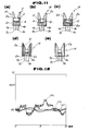
- Fig. 14 is a diagram of experimental data showing temperature readings obtained when the photoclinical thermometer of this embodiment was operated continuously for 30 minutes in a position facing a black body furnace held at 40 ° C while the outer periphery of the housing was heated at 45 . C by a vinyl heater.
- the x-mark represents data obtained in the absence of a ventilating portion
- the o-mark represents data obtained in the presence of a ventilating portion.
- thermometer capable of measuring the body temperature quickly and easily which thermometer has been subjected to room temperature correction for the infrared sensor and prevented from causing a measurement error based on the rise of temperature upon insertion of the housing tip into the ear or oral cavity.
- Figs. 15(a) and 15(b) are a schematic perspective view and a schematic sectional view of a photoclinical thermometer (a mirror type) embodying the second invention
- Figs. 16(a) to 16(c) are each a schematic perspective view of the tip portion of a probe of the photoclinical thermometer.
- numeral 61 denotes an inserting portion formed in the shape of a tripod
- numeral 62 denotes a holding portion for the inserting portion 61 which holding portion is formed of a plastic material
- numeral 63 denotes an inserting portion formed in the shape of a net.
- the inserting portions 61 and 62 of the tip portion 12 of the photoclinical thermometer are formed using metallic rods or wires superior in heat conductivity to improve the heat radiation of the tip portion 12.
- the inserting portion 61 of the tip portion 12 is formed by three metallic legs, with a tip end 61 thereof being formed in the shape of a ring of about a size permitting insertion into the human ear cavity. It is desirable that the tip end 61a a be formed of a metal of high thermal conductivity such as, for example, copper or aluminum. In Fig. 16(a), the diameter of the tip end 61 a is about 8 mm and legs 61 b of the inserting portion 61 are fixed into the holding portion 62 formed of a plastic material.
- the legs 61 b are fixed so that the respective rear ends are embedded in the front end of the holding portion 62. And the legs 61 b of the inserting portion 61 are tapered at the same angle as the side part of the holding portion 62 so that the whole of the tip portion 12 is generally in a conical shape.
- the diameter of the tip end 61 a of the inserting portion 61 is also about 8 mm like that in Fig. 16(a)
- the holding portion 62 is formed in a conical shape. Reduction of the diameter of the tip end 61a to about 6 mm permits the use as a photoclinical thermometer for children.
- Fig. 16(b) although the diameter of the tip end 61 a of the inserting portion 61 is also about 8 mm like that in Fig. 16(a), the holding portion 62 is formed in a conical shape. Reduction of the diameter of the tip end 61a to about 6 mm permits the use as a photoclinical thermometer for children.
- the inserting portion 63 is formed in the shape of a net using a metal of high thermal conductivity, e.g. aluminum, which is attached to the holding portion 62.
- a metal of high thermal conductivity e.g. aluminum
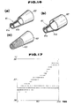
- Fig. 17 shows experimental data obtained by measuring the body temperature 100 times continuously for about 30 minutes using the photoclinical thermometer of the embodiment shown in Fig. 16(a) and like data obtained by making the measurement in the same manner using a photoclinical thermometer having a probe tip end formed wholly of a plastic material.
- the x-mark represents the data obtained using the photoclinical thermometer having a probe tip portion formed entirely of a plastic material
- the o-mark shows the data obtained using the photoclinical thermometer shown in Fig. 16(a).
- the body temperature readings rise above 1 C, causing an error.
- the rise in temperature of the tip portion 12 can be prevented during temperature measurement to minimize the occurrence of measurement error by forming the tip portion 12 us.ing metallic rods or wires of good heat radiation.
- Other functions and effects are the same as in the first embodiment.
- Fig. 18 illustrates a basic construction of a photoclinical thermometer according to a first embodiment of the third invention, in which a temperature measuring element 4b is also attached to a tip portion 12 to correct a temperature measurement error caused by a change in temperature of the tip portion 12 during temperature measurement.
- numeral 4a denotes a temperature measuring element for measuring room temperature
- numeral 4b denotes a temperature measuring element for measuring the temperature of the tip portion 12
- numeral 24 denotes an arithmetic unit for converting the output of the temperature measuring element 4b into voltage.
- the temperature measuring element 4b At the tip portion 12 is disposed the temperature measuring element 4b to measure the temperature of the tip portion.
- the temperature measuring element 4a is disposed in a support 2 to measure the temperature of an infrared sensor 3 in accordance with the ambient temperature of the sensor.
- the temperature measuring elements 4a and 4b are each constituted by a resistance bulb, e.g. a thermistor, or a diode or the PN junction of a transistor.
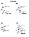
- the temperature measuring element 4b may be embedded in the tip portion 12 as a one point measuring element of a small-sized round or square shape, as shown in Fig. 20(a), or it may be stuck on the inner surface of the tip portion as a thin film (e.g. 0.1 mm thick) element of a wide area, as shown in Fig. 20(c), or it may be in the shape of a ring fitted inside the tip portion, as shown in Fig. 20(d). It is also effective to apply a cover 13 onto the tip portion 12, as shown in Fig. 20(b), to prevent the temperature measuring element 4b from measuring the circumferential surface temperature of a cavity, e.g. the ear cavity, and also prevent the rise in temperature of the tip portion 12 when inserted into the ear cavity.
- a cover 13 onto the tip portion 12
- a processing section 20 shown in Fig. 18 is provided with a signal amplifier 21 for amplifying the output Vs of the infrared sensor 3; an arithmetic unit 22 for converting the output (change in resistance) of the temperature measuring element (thermistor) 4a into voltage Vo; an arithmetic unit 24 for converting the output (change in resistance) of the temperature measuring element (thermistor) 4b into voltage Vr; and a signal processor 23 which receives the output V of the amplifier 21 and the outputs Vo, Vr of the arithmetic units 22, 24 and provides a body temperature signal S.
- the amplifier 21, arithmetic units 22, 24 and signal processor 23 may be constituted each individually, or integrally as shown in Figs. 21 and 22. Other constructional points are the same as in the foregoing first embodiment.
- the dotted line X2 in Fig. 19(a) represents infrared ray radiated from the inner surface of the housing tip portion 1 2 into the infrared sensor 3.
- This kind of phenomenon occurs in the body temperature measurement using infrared ray, but scarcely causes a problem in the case where the object to be measured for temperature is high in temperature.
- a slight error e.g. an error of 0.1 ° C at a temperature rise of 2°C
- the output Vr of the arithmetic unit 23 corrects such error.
- the signal processor 23 corrects the ambient temperature of the infrared sensor 3, outputs a correct body temperature signal S after temperature correction for the tip portion 12 inserted into the ear cavity, and causes a display unit in a display section 30 to display the body temperature.
- the signal S is an analog signal when the display unit is an analog type, or it is a digital signal when the display unit is a digital type.
- the temperature correction for the tip portion 12 will now be explained.
- the whole of the probe 10 is regarded as a measuring instrument, which is corrected using a black body furnace. It is also processed by a signal processor so as not to be influenced by room temperature. Therefore, as long as the temperature of the probe tip 12 and that of the probe body (the portion where the infrared sensor 3 is located) are equal, there will be no influence of the tip portion 12.
- the temperature measurement When the tip portion is inserted into the ear cavity, the temperature measurement will be completed in several seconds, but where the temperature measurement is to be repeated, the temperature of the tip portion 12 will gradually become higher than room temperature, causing an increase in dose of the infrared ray which is radiated from the tip portion into the infrared sensor 3, so the temperature value displayed will be a little higher.
- the error generated is 0.1 C when the difference between room temperature and the temperature of the tip portion 12 is 2°C, under the conditions of an opening 12a being
- the electromotive force generated, Vs, of the infrared sensor (thermopile) 3 is proportional to a (T 4 - T 0 4 ) (T: temperature of the object measured, To: room temperature).
- the a is a correction coefficient which is determined by the components (optical elements: lens, mirror, shape, solid angle). Where the range of measurement is narrow, that is, in the vicinity of the body temperature
- R , y and t represent a resistance value at 0°C, a temperature coefficient and a measured temperature (unit: C), respectively.
- JIS applies.
- Tr > To the dose of the infrared ray incident on the thermopile 3 increases, while it decreases when Tr ⁇ To. Therefore, when Tr > To, the calculated temperature T is rather high, while when Tr ⁇ To, it is rather low.
- the amount of correction is determined by the shape of the probe tip 12 and optical elements. In the characteristics of the foregoing lens construction, the amount of correction is 0.1 ° C at a temperature difference [Tr - Tol of 2. C.
- the signal processor 23 processes the aforementioned contents (digital processing or analog processing, or a combination of both) to determine a true temperature T of the object measured and displays it on the display unit 30.
- the processing section 20 may be constructed so that the infrared sensor 3 and the temperature measuring elements 4a, 4b are incorporated wholly or partially in the circuit of the processing section as shown in Figs. 21 and 22 to obtain a temperature-compensated output S.
- the reference marks R and VR represent a resistor and a variable resistor, respectively, (the subscripts 1, 2, ... are for distinguishment from each other and may be omitted herein).
- a variable resistor VR i is for adjustment of the output voltage Vr of the temperature measuring element 4b.
- Fig. 21 (b) the temperature measuring element 4a, a variable resistor VR Z , the temperature measuring element 4b and a resistor R 2 are series- connected in this order and an electric current I is flowed from a constant voltage source, with the infrared sensor 3 being connected to a slider of the variable resistor VA z . At this slider there is obtained Vo - Vr, so the output S at the other end of the infrared sensor 3 becomes Vs + Vo - Vr.
- Fig. 21 (e) an electric current is flowed through the temperature measuring elements 4a and 4b to develop Vo and Vr, which are received by an arithmetic unit 16.
- Figs. 22(a) and 22(b) show examples in which a temperature measuring element having a positive temperature coefficient such as a platinum resistance bulb is used as the temperature measuring element 4a for the correction of room temperature, and a temperature measuring element having a negative temperature coefficient such as an ordinary thermistor is used as the temperature measuring element 4b for the correction of the temperature of the probe tip portion.
- a constant voltage source E and a constant current source respectively, in both of which there is obtained Vo - Vr at the output end P, so this may be added to the output of the infrared sensor.
- this photoclinical thermometer is inserted into a cavity such as the ear or oral cavity for the measurement of its temperature, it is necessary to keep it clean.
- the use of such a cover as shown in Fig. 20(b) is hygienically effective because it can be made disposable or removed for washing.
- the tip end 12a is effective to have the tip end 12a opened in point of conducting infrared ray without loss into the housing 11, but the open tip end is disadvantageous in that dust will get in the interior of the housing 11. To prevent this, it may be effective to cover the tip end 12a with an infrared ray transmitting window.
- Fig. 23 is a schematic perspective view showing a first application example of the embodiment of the third invention, and Figs. 24(a), (b) show related plot and print example, respectively.
- a memory module and a printer are combined with the photoclinical thermometer of the embodiment of the third invention to thereby permit storage and recording of data.
- the numerals 71, 72 and 73 denote a measuring portion body, a memory module and a printer, respectively.
- a hold switch 71a and a symbol M showing that the present display is memory, is indicated on the display section 30.
- a memory address display 72a On the memory module 72 are mounted a memory address display 72a, a memory address count-up/count-down button 72b and a display change-over button 72c for the change-over of display between measured value and memory.
- a printer 73 Mounted on the printer 73 are a single data printing button 73a, a plotting button 73b and a printing button 73c for all data.
- Numeral 80 denotes a printing paper.
- the memory module 72 and the printer 73 are separated from the measuring portion body 71 and only the latter is used.
- the memory module 72 is coupled to the measuring portion body 71 to store data.
- the memory module 72 may contain calendar and clock functions, whereby the month, date and time can be stored automatically.
- the printer 73 is coupled to the memory module 72 to print out the values. Upon depression of the plotting button 73b there is obtained the output shown in Fig. 24(a), while when the all-data printing button 73c is pushed, there is obtained the output shown in Fig. 24(b).
- This application example is convenient when a multitude of measurement data are required; for example, it is particularly effective when used as a clinical thermometer for ladies or when used for measuring the temperature distribution of the surface of human body.
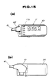
- Fig. 25 is a schematic perspective view showing a second application example of the embodiment of the third invention, in which application example the clinical thermometer embodying the third invention is formed as a desk-top type for domestic use.
- the probe 10 is received in a groove 35 of a body 39 and the processing section 20 is mounted within the body 39.
- the display section 30 may be an analog or digital type or a caricature type which displays the body temperature classifiedly like normal, feverish, and having a high fever, using caricatures respectively. In the latter case, as the display unit it is suitable to use a liquid crystal display unit.
- the body 39 there are also provided a memory and a printing mechanism though not shown.
- Numeral 36 denotes a printing paper
- numeral 37 denotes a paper feed button
- numerals 31 to 34 also represent push-buttons, of which the push-button 31 is for the input of temperature-measured month, date and time, the button 32 is for storing the results of temperature measurement into the memory, the button 33 is for instructing display, and the button 34 is for instructing printing.
- Numeral 38 denotes a calendar, which is driven by a clock mechanism incorporated in the body 39 to display month and date.
- Figs. 26(a) to 26(c) are schematic perspective views showing a third application example of the embodiment of the third invention, of which Figs. 26(a) and 26(b) illustrate photoclinical thermometers each formed in the shape of a pencil.
- a probe 10 integral with the body portion (processing and display sections 20, 30).
- Numeral 18 denotes a cap for covering the probe tip portion. When the photoclinical thermometer is not in use, the cap 18 is fitted over the probe tip portion to protect the tip opening (12a), etc. It is hygienically suitable to put inside the cap 18 a porous elastic material impregnated with an antiseptic liquid such as alcohol.
- Numeral 19 denotes a switch for instructing the start of measurement (application of power).
- a pressure sensor to make display upon response thereof to pressure when the tip end is inserted into the ear cavity.
- a holding means for holding the result of temperature measurement to let the display section 30 keep on displaying the maximum temperature until reset, so that it is possible to know the body temperature by seeing the display section 30 after pulling the probe tip portion from the ear cavity.
- Fig. 26(c) illustrates a pistol-shaped photoclinical thermometer.
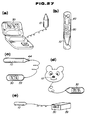
- Figs. 27(a) to 27(e) are schematic perspective views showing other application examples of the embodiment of the third invention.
- Fig. 27(a) shows a photoclinical thermometer of a shape similar to that of a compact for ladies; Fig.
- FIG. 27(b) shows a photoclinical thermometer integral with a lipstick 43
- Fig. 27(c) shows a photoclinical thermometer having a cylindrical probe 10 which can be separated from the body portion at the part of a socket 44
- Fig. 27(d) shows a photoclinical thermometer for children having a probe in the shape of an animal nose
- Fig. 27(e) shows a photoclinical thermometer for use in medical institution, with long-term monitor/diagnostic memory as well as recorder/plotter being provided in a body portion 39.
- the respective photoclinical thermometers are each provided at the tip portion thereof with the temperature measuring element 4b, this does not mean any limitation.
- the tip portion may be heat-insulated as in the embodiments of the first invention, or the tip portion of the housing may be formed using a metallic net of good heat radiation as in the embodiment of the second invention.
- thermometer which has been subjected to room temperature correction and temperature correction for the probe tip portion and which can measure the body temperature quickly and easily.
- the above first and third inventions are not limited to the embodiments described above. For example, they may be used for measuring the temperature of not only the human body but also animals.
- the photoclinical thermometer of the present invention is useful as a clinical thermometer for measuring the human body temperature. Particularly, it is suitable for the case where it is required to measure the body temperature correctly in a short time, for example, when infants, sick persons, or a large number of persons, are to be measured for body temperature.
Abstract
Description
- The present invention relates to a photoclinical thermometer using an infrared sensor and particularly to the correction of a temperature measurement error for the same.
- Heretofore, as a clinical thermometer there has widely been used a mercury thermometer, but recently a digital electronic clinical thermometer has also come into wide use.
- Ordinary electronic clinical thermometers use a thermistor as a sensor and are provided with an arithmetic circuit for the calculation of temperature values and a digital display unit. But it takes two to three minutes for the measurement of temperature, which time is even longer than that required in mercury clinical thermometer. There is an electronic clinical thermometer of the type in which the final value is estimated from the progress of temperature rise during an initial one minute or so. But this type of an electronic clinical thermometer involves the problem that the so-estimated value is not always coincident with an actual value.
- The problem of requiring time for the measurement of temperature is also related to the portion where the temperature is to be measured. It is the temperatures of such deep parts as head, chest and abdominal cavity that are maintained at predetermined values by the adjusting function of a living body. But is is difficult to directly measure the temperatures of those deep parts, so in general the temperature to be measured is rectal temperature, oral temperature, or axilla temperature. The axilla temperature measurement is widely adopted, but the axilla is usually in a somewhat open condition, so the skin temperature of that part is a little lower. When the axilla is closed with a clinical thermometer put therein, the skin temperature will begin rising and reach a certain temperature (equilibrium temperature) in 10 minutes or so. If at this point or thereafter the clinical thermometer is pulled out and checked, there will be obtained an accurate axilla temperature. But if the clinical thermometer is pulled out earlier, the temperature value shown thereon will be a little lower.
- Another factor related to the temperature measurement time is the heat capacity of the sensor portion. In a mercury clinical thermometer, the temperature measurement goes through the process of warming the mercury bulb by the body temperature through the glass wall and reading the expansion of mercury, so the heat capacity of the object warmed is farily large, requiring a measurement time of 2 to 3 minutes. Also in an electronic clinical thermometer, a metallic portion contacted with a part for measurement is warmed by the body temperature and the thermistor varies its resistance value depending on the temperature of the metallic portion, so the heat capacity of the object warmed (the metallic portion) is also large.
- All of the above clinical thermometers are a contact type, but there also are available non-contact type clinical thermometers, an example of which is the "non-contact type oral thermometer" disclosed in Japanese Patent Laid-Open No. 88627/83. In this oral thermometer, using a pyroelectric type infrared sensor, infrared ray from the oral cavity is condensed and input to the sensor after chopping, while the output of the sensor is amplified and calculation is made on the basis of a reference temperature signal to determine the body temperature, which is displayed on a display unit. Alternatively, using a thermistor as an infrared sensor, the oral thermometer is composed of a condensing system, the thermistor, an amplifier, an arithmetic unit, a display mechanism and a reference temperature detector.
- As the method of measuring the body temperature by inserting a clinical thermometer into the ear cavity there have been proposed such methods as those disclosed in Japanese Patent Laid-Open Nos. 25427/85, 216232/85, 133331/85, 117422/86, 138130/86, and U.S. Patent No. 3,282,106 (1966). However, these proposed methods have not been realized yet because of the following problems involved therein.
- The patent laid-open 25427/85 is merely entitled "an ear-plug type body temperature sensor". It is uncertain whether the body temperature is measured by a contact heat transfer of a resistance bulb such as a thermistor or by using such a sensor as an Si sensor for detecting infrared ray. Thus, since it is uncertain what measuring means is used, it is actually impossible to constitute a clinical thermometer.
- The patent laid-open 216232/85 discloses an earplug type which measures the body temperature by a contact heat transfer with the external auditory meatus, using a thermistor as a temperature sensor. However, since this method is a contact type, it can be easily estimated that a longer temperature measuring time is required than in an oral type electronic clinical thermometer.
- The patent laid-open 133331/85 discloses an ear sealing type, which however is basically the same as the ear-plug type of the patent laid-open 216232/85 because it uses a thermistor and a transistor sensor as temperature sensors.
- The patent laid-open 117422/86 discloses an ear insertion type using a thermopile as an infrared sensor. According to the method set forth therein, the sensor portion is maintained at a certain constant temperature and the body temperature is measured by a reference method, using a reference temperature source provided in the device. This method is technically superior, but a complicated construction is needed for maintaining the temperature of the sensor portion constant and for the provision of a reference temperature source, thus obstructing a low-cost production.
- The patent laid-open 138130/86 discloses a method wherein infrared ray from the ear cavity is conducted to a pyroelectric sensor through an optical fiber. But an infrared optical fiber for the measurement of body temperature has not been developed yet. The wavelength band of the energy radiated from the body temperature is in the range of 8 to 13 µm and there has not been developed a fiber capable of fully transmitting radiation of such wavelength band. At ordinary temperatures or thereabouts, such radiation from the fiber itself is not negligible, so from the standpoint of accuracy it is difficult to realize a clinical thermometer using an optical fiber. Even if such clinical thermometer were realized, it would be very expensive.
- The U.S. patent 3,282,106 (1966) entitled "Method of Measuring Body Temperature" is concerned with a method of measuring the body temperature by detecting in a non-contact manner an infrared ray of 10 µm in wave length emitted from a body cavity of a mammal typical of which cavity is the ear cavity. But this method is disadvantageous in that there occurs a temperature error because the change in temperature of the sensor portion is not considered.
- Thus, the contact type clinical thermometers involve the problem that the time required for temperature measurement is long, and the conventional non-contact type clinical thermometers which are sensitive to infrared rays involve the problem of construction being complicated and the cost high.
- It is an object of the present invention to remedy the above-mentioned drawbacks and provide a photoclinical thermometer capable of measuring the body temperature in a shorter time, simple in construction, capable of being fabricated inexpensively and that superior in the measurement accuracy. According to the present invention the body temperature is measured by inserting the clinical thermometer into a cavity such as the ear cavity or the oral cavity, but in this case, there is the problem that the temperature of the tip portion of a housing inserted into the cavity is raised by the body temperature, causing a measurement error. It is therefore another object of the present invention to prevent the occurrence of a temperature measurement error by making such rise of temperature negligible.
- According to a first invention for achieving the above-mentioned objects, there is provided a photoclinical thermometer including an infrared sensor (3) disposed within a housing (11), an optical system (5) for condensing infrared ray to the said infrared sensor which infrared ray is incident from a tip portion of the housing as inserted into a body cavity, a temperature measuring element (4) for measuring the ambient temperature of the infrared sensor, a heat insulator (6) mounted on the said tip portion, a processing section (20) for outputting a body temperature signal after correction for the ambient temperature of the infrared sensor, and a display unit (30) which receives the said body temperature signal and displays the body temperature visually.
- According to a second invention for achieving the above-mentioned objects, there is provided a photoclinical thermometer including an infrared sensor (3) disposed within a housing (11), an optical system (5) for condensing infrared ray to the said infrared sensor which infrared ray is incident from a tip portion of the housing as inserted into a body cavity, a temperature measuring element (4) for measuring the ambient temperature of the infrared sensor, a processing section (20) for outputting a body temperature signal after correction for the ambient temperature of the infrared sensor, and a display unit (30) which receives the said body temperature signal and displays the body temperature visually, said tip portion being formed by a linear member or a rod-like member.
- Further, according to a third invention for achieving the above-mentioned objects, there is provided a photoclinical thermometer including an infrared sensor (3) disposed within a housing (11), an optical system (5) for condensing infrared ray to the said infrared sensor which infrared ray is incident from a tip portion of the housing as inserted into a body cavity, a first temperature measuring element (4a) for measuring the ambient temperature of the infrared sensor, a second temperature measuring element (4b) for measuring the temperature of the said tip portion, a processing portion (20) which receives the outputs of the infrared sensor and the first and second temperature measuring elements and outputs a body temperature signal after correction for the ambient temperature of the infrared sensor and for the temperature of the housing tip portion, and a display portion (30) which receives the said body temperature signal and displays the body temperature visually.
- According to the photoclinical thermometers of the constructions of the above first to third inventions, even if in the temperature measurement the temperature of the housing tip portion as a temperature measuring part changes in contact with the ear or oral cavity of human body as a part to be measured for temperature, it is possible to measure the body temperature accurately, with few errors in the measurement, and that quickly and easily.
-
- Fig. 1 is a view showing a basic construction of a photoclinical thermometer according to a first embodiment of the first invention;
- Fig. 2 comprises a schematic perspective view and a schematic sectional view, of an integral lens type photoclinical thermometer;
- Fig. 3 is a schematic perspective view of a separative lens type photoclinical thermometer;
- Fig. 4 comprises a schematic perspective view and a schematic sectional view, of an integral mirror type photoclinical thermometer;
- Fig. 5 is a schematic view of a separative mirror type photoclinical thermometer;
- Fig. 6 is a view showing black body temperature vs. thermopile output;
- Figs. 7 and 8 are views each showing the structure of a heat insulator;
- Fig. 9 is a view showing an example of construction of a processing section;
- Fig. 10 is a view showing another example of construction of a processing section;
- Fig. 11 is a view showing a sensor portion according to a second embodiment of the first invention;
- Fig. 12 is a schematic sectional view showing experimental data thereof;
- Fig. 13 is a schematic view of a third embodiment of the first invention;
- Fig. 14 is a view showing experimental data thereof;
- Fig. 15 comprises a schematic perspective view and a schematic sectional view, of a photoclinical thermometer (mirror type) according to an embodiment of the second invention;
- Fig- 16 is a schematic perspective view of a tip portion of a probe used therein;
- Fig. 17 is a view showing experimental data thereof;
- Fig. 18 is a view showing a basic construction of a photoclinical thermometer according to an embodiment of the third invention;
- Fig. 19 is an explanatory view of an intra-probe optical system;
- Fig. 20 is a schematic view showing a temperature measuring element as mounted to the tip portion of the probe;
- Figs. 21 and 22 are views showing examples of construction of a processing section;
- Fig. 23 is a schematic perspective view showing an application example of the embodiment of the third invention;
- Fig. 24 is a view showing a plotting example and a print example;
- Fig. 25 is a schematic perspective view showing a second application example of the embodiment of the third invention;
- Fig. 26 is a schematic perspective view showing a third application example of the embodiment of the third invention; and
- Fig. 27 is a schematic perspective view showing other application examples of the embodiment of the third invention.
- A first embodiment of the first invention will now be described with reference to Figs. 1 to 10. Figs. 1 (a) and 1(b) illustrate a basic construction of a photoclinical thermometer according to a first embodiment of the first invention. This photoclinical thermometer broadly comprises a
probe 10, aprocessing section 20 and adisplay section 30. - The
probe 10 has a housing 11, within which are mounted an infrared sensor, e.g. athermopile 3, asupport 2 for the sensor, and an optical system 5 [lens in Fig. 1 (a), mirror in Fig. 1 (b)]. The housing 11 is formed with atip portion 12 to be inserted into a cavity such as the ear or oral cavity, thetip portion 12 having size and shape conforming to such cavity, with aheat insulator 6 being mounted on the tip portion. Atemperature measuring element 4 is disposed in thesupport 2 to measure the ambient temperature of theinfrared sensor 3 and hence the temperature of the same sensor. Thetemperature measuring element 4 is constituted by a resistance bulb such as thermistor, or a temperature measuring IC such as diode or transistor. - The
tip portion 12 has anopen tip end 12a. Infrared ray radiated from the foregoing cavity passes through theopening 12a and enters the housing, in which it is condensed by the lens for infrared ray ormirror 5 and enters theinfrared sensor 3. In this incident path is placed adiaphragm 1, and the portion of thesupport 2 corresponding to the incident path forms an aperture. Acircumferential surface 2a of the aperture is conical. Together with thediaphragm 1, the conicalcircumferential surface 2a determines a solid angle of the infrared ray incident on theinfrared sensor 3. Thecircumferential surface 2a is darkened for infrared rays - (wave length: 5 - 20pm).
- The
processing section 20 includes asignal amplifier 21 for amplifying the output, Vs, of theinfrared sensor 3, anarithmetic unit 22 for converting the output (change in resistance) of the temperature measuring element (thermistor) 4, and asignal processor 23 which receives the output, V, of theamplifier 21 and the output, Vo, of thearithmetic unit 22 and outputs a body temperature signal S. Theamplifier 21,arithmetic unit 22 andsignal processor 23 may be constituted each individually or integrally. - The
processing section 20 and thedisplay section 30 may be constituted integrally with or separately from theprobe 10, as shown in Figs. 2 to 5. Figs. 2(a) and 2(b) are a schematic perspective view and a schematic sectional view, respectively, of a lens type photoclinical thermometer, in which a probe, a processing portion and a display portion are formed integrally. Fig. 3 is also a schematic perspective view of a lens type photoclinical thermometer, in which, however, a probe is separated from a processing section and a display section. Figs. 4(a) and 4(b) are a schematic perspective view and a schematic sectional view, respectively, of a mirror type clinical thermometer, in which a probe, a processing section and a display section are formed integrally. Fig. 5(a) is also a schematic perspective view of a mirror type photoclinical thermometer, in which, however, a probe is separated from a processing section and a display section. In the separate construction, theprobe 10 may be disposed within theprobe 10, as shown in Fig. 5(b). - According to the above construction, in measuring the body temperature, the
tip portion 12 of theprobe 10 is inserted, for example, into the ear cavity, and infrared ray radiated from the ear cavity in accordance with the temperature of the cavity passes through thetip end opening 12a and enters the interior of the housing 11. The incident infrared ray is converged by the lens ormirror 5 and radiated to theinfrared sensor 3. Therefore, the output Vs of theinfrared sensor 3 corresponds to the incident infrared ray, that is, the internal temperature of the ear cavity, and hence the body temperature. - However, as shown in Fig. 6, the output Vs of the
infrared sensor 3 also varies depending on the ambient temperature. The axis of ordinate and that of abscissa in Fig. 6 represent the output Vs and the black body (ear cavity temperature and hence the body temperature) Tb, respectively, and the curves C1, C2, C3 in the same figure are Vs-Tb curves at room temperatures (ambient temperatures) of 0°, 20° and 40 C, respectively. As is apparent from this graph, in order to check the body temperature it is necessary to know room temperature, i.e., ambient temperature of the infrared sensor, in addition to the output Vs of the infrared sensor. Thearithmetic unit 22 provides this room temperature. - When the
housing tip portion 12 is inserted into the ear cavity, its temperature rises and so the dose of the infrared ray radiated from thetip portion 12 changes (increases), causing an error. Such a phenomenon occurs in the temperature measurement using infrared ray, but this scarcely causes any problem in the case where the temperature of the object to be measured is high. However, where the temperature of the object to be measured is low such as the body temperature, the above phenomenon causes a small error (e.g. an error of 0.1 C at a temperature rise of 2. C). Theheat insulator 6 covers thehousing tip portion 12 to insulate the latter from heat, thereby preventing the tip portion from rising in temperature during the measurement of temperature. - Using the output voltage V of the
amplifier 21 and the output voltage Vo of theamplifier 22, thesignal processor 23 outputs a correct body temperature signal S after correction of the ambient temperature of the infrared sensor and causes thedisplay unit 30 to display the body temperature. When the display unit is an analog type, the signal S is an analog signal, while when it is a digital type, the signal S is a digital signal. - The temperature correction for the output of the
infrared sensor 3 will now be explained. The electromotive force generated, Vs, of the infrared sensor (thermopile) 3 is proportional to a (T4 - To4) wherein α, T and To represent a coefficient, temperature of the object measured, and room temperature, respectively, (T and To both being absolute temperatures). Where the range of measurement is narrow, the error is very small even if calculation is made according to a linear approximation. In other words, the electromotive force generated, Vs, may be assumed to be proportional to j6 (T - To) (p: constant determined by the temperature measurement range, or a coefficient dependent on components, lens, mirror, shape and solid angle). - If the
temperature measuring element 4 is a resistance bulb such as platinum resistance bulb, the change in resistance caused by the change of temperature can be represented as Ro = R (I + -yt) wherein R , y and t represent a resistance value at 0°C, a temperature coefficient and a measured temperature, respectively. In the case of a platinum resistance bulb, JIS applies. A temperature sensing element which exhibits negative characteristics such as a thermistor is also employable. - Since the amplified voltage V of the output Vs of the
thermopile 3 is an output proportional to the difference between the internal temperature T of the ear cavity and room temperature To, (V = S (T - To)), the difference in temperature, AT ( T - To), is determined by V/β. Since the room temperature To is determined from the output Vo of thetemperature measuring element 4, the temperature T of the object measured is calculated from To + V/0. - Figs. 7 and 8 are views each showing the structure of the
heat insulator 6. In Fig. 7(a), theheat insulator 6 is in the form of a thin-walled cap 6a having lugs at the tip or rear end thereof. Theheat insulator 6 is in constant with the outer peripheral surface of thehousing tip portion 12 through thelugs 61 to form anair gap 13 between the inner surface of the cap and the outer peripheral surface of the housing - tip portion. The
air gap 13 effects heat insulation. When the tip portion of theprobe 10 is inserted into the ear or oral cavity, the temperature of thetip portion 12 rises due to the body temperature and the dose of infrared ray radiated from the inner surface of the tip portion increases. If the infrared ray should enter theinfrared sensor 3, there would occur an error in the temperature measurement, but the presence of theair gap 13 prevents the rise in temperature of thehousing tip portion 12, whereby the occurrence of error mentioned above is prevented. - The
lugs 61 are preferably small in area to reduce the heat transfer therethrough. To this end, in Fig. 7(b), threelugs 61 of a narrow width are disposed at intervals of 120 °, while in Fig. 7(c), twolugs 61 are provided at an interval of 180°. The lugs shown in Fig. 7(c) are larger in width than the lugs in Fig. 7(b) from the standpoint of safety. - The
cap 6a is required to have rigidity to some extent so may be formed of a metal or a rigid plastic, but not limited thereto. - In Fig. 8(a), the heat insulator is in the form of a
cap 6b formed of a thick-walled heat insulating material. Since it is fitted on thehousing tip portion 12, its inner peripheral surface is of the same shape as the outer peripheral surface of the said tip portion. Fig. 8(b) is a perspective view of thecap 6b. Thecap 6b may be formed of such a material as polyurethane, polystyrene foam, glass wool, paper, or cotton. - The
opening 12a of thehousing tip portion 12 may be covered with a thin plate such as, for example, a silicon, germanium or polyethylene plate. In this case, such thin plate may be attached to the cap. The cap may be fixed to thehousing tip portion 12, or it may be rendered removable. - It is also effective to form the inner surface of the housing tip portion 12 (the inner surface from the
tip end 12a up to the lens or mirror 5) as a mirror surface if possible. More particularly, since the mirror surface is small in emissivity, even if the temperature of thehousing tip portion 12 rises during the temperature measurement, the change in dose of the infrared ray radiated from the inner surface of the said tip portion will be small and hence the measurement error small. Therefore, it is extremely effective to subject the inner surface of the tip portion to vapor deposition of gold or aluminum or plating of gold or aluminum. - Figs. 9(a) and 9(b) show examples of construction of the
processing section 20. In Fig. 9(a), the numeral 25 denotes an adder (subtracter), which receives the output of an infrared sensor (athermopile 3 in this example) and that of a temperature measuring element (athermistor 4 in this example) and outputs a body temperature signal S on the basis of the sum of both outputs. Since V = β (T - To), Vo α To, the body temperature V is determined by multiplying V by 1/S and then adding the signal To from the temperature measuring element. Numeral 26 denotes a resistor, which is connected across a power source in series with thethermistor 4, with an output voltage Vo developed at a junction P. For example, as shown in Fig. 6, if the thermopile outputs at points a, b and c are Va, Vb and Vc, respectively, the thermopile output at a black body temperature of Tbi and at room temperature of 20 C is Vb, lower by Va - Vb than the output Va at a room temperature of 0° C. If this Va - Vb is generated by thethermistor 4, the black body temperature Tb can be determined from the thermopile output in a corrected state at 0 C. - In Fig. 9(b), a
thermistor 4, avariable resistor 27 and a fixedresistor 28 are connected in series across a power source and one end of thethermopile 3 is connected to a slider of thevariable resistor 27, from the other end of which is taken out a temperature signal S. Also in this construction, the above calculations are performed. Thevariable resistor 27 is for adjusting the temperature characteristic of the output Vo. - Another constructional example of the
processing section 20 is shown in Fig. 10. In Fig. 10,numerals numerals thermopile 3 and the temperature measuring element (room sensor) 4 are converted to sufficiently large signals by means ofamplifiers 51 each having an appropriate amplification factor, which signals are then fed to double integrating circuits 52 (a kind of A/D converter), respectively. The double integratingcircuits 51 provide pulses to theCPU 53 which pulses each have a time width proportional to the input signal. TheCPU 53 measures those pulses for time width using an internal counter. The count values corresponding to the signals from thethermopile 3 and thetemperature measuring element 4 respectively are multiplied by coefficients which have been set by thecoefficient setting section 54, to correct a solid difference in the sensor characteristics. A final temperature value calculated by applying an arithmetic processing to the count values after correction by theCPU 53 is fed as a display value to thedisplay section 30. Thecoefficient setting section 54 is composed of arrayed diodes D and switches S and is connected to the input/output port 55 of theCPU 53, whereby it can digitally set coefficient values not changing with time, thereby permitting correction of the sensor characteristics. As a result, it becomes unnecessary to use RAM and so it is possible to reduce the power consumption. In place of the mechanical contacts of the switches S shown in Fig. 10 there may be used thin film conductors, whereby thecoefficient setting section 54 can be reduced in size and cost as compared with the mechanical switches. - According to the above first embodiment it is possible to make room temperature correction for the
thermopile 3 and the rise in temperature of thetip portion 12 in the measurement of temperature can be prevented by theheat insulator 6 fitted on thetip portion 12, so it is possible to diminish the occurrence of measurement error. - Fig. 11 is a schematic sectional view showing a sensor portion comprising a thermopile, a temperature measuring element and a support, of a photoclinical thermometer according to a second embodiment of the first invention. In Figs. 11 (a) to 11 (e), numeral 14 denotes a sensor portion;
numerals thermopile 3; andnumerals temperature measuring element 4. Since this embodiment is the same as the foregoing first embodiment except thesensor portion 14, there will be omitted a perspective view and a block diagram of this embodiment. Also, in the second embodiment illustrated in Figs. 11 (a) to 11 - (e) as well as a third embodiment and embodiments of the other inventions which will be described later, the components having the same functions as in the above embodiment shown in Figs. 1 to 10 will be designated by the same reference numerals and detailed explanations thereon will be omitted. - The second embodiment is different from the first embodiment in that a
temperature measuring element 4 as a room temperature sensor is bonded to the bottom of athermopile 3 and both are embedded in a support which includes a high thermal conductivity member. The sensor portion shown in Fig. 11(a) is formed by bonding the temperature measuring element 4 (e.g. a posistor) to the bottom of thethermopile 3, embedding thetemperature measuring element 4 in a copper block 2i having a thickness of about 5 mm and enclosing them with aplastic material 22 superior in heat insulating property. In the sensor portion shown in Fig. 11 (b), there is used a thermopile 3 a little smaller than that shown in Fig. 11 (a) and boththermopile 3 andtemperature measuring element 4 are embedded in thecopper block 2,. In the sensor portion shown in Fig. 11 (c), in order to further reduce the influence of the heat transfer from the exterior of the sensor portion, boththermopile 3 andtemperature measuring element 4 are embedded in thecopper block 2,, and a heat insulating material 23 (e.g. polyurethane, ceramic, or glass fiber) is disposed outside thecopper block 21, further, acopper pipe 24 is disposed outside theheat insulating material 23, which are all enclosed with theplastic material 22. The sensor portion shown in Fig. 11 (d) is a modification of Fig. 11 (c) and that shown in Fig. 11 (e) is a modification of Fig. 11 (b). Thelead wires sensor portion 14 through holes (not shown) formed in the copper block 2i. They are coated to prevent short-circuit therebetween. Thecopper block 2, may be replaced with any other metal block if only the metal is superior in heat conductivity, e.g. aluminum. - Fig. 12 is a diagram of experimental data showing temperature readings obtained when the photoclinical thermometer of this embodiment was operated continuously for 10 minutes in a position facing a black body furnace held at 40 C. The mark (s) represent readings obtained without using the copper block; the mark (a) represents readings obtained using the sensor portion shown in Fig. 11-(a); and the mark (c) represents readings obtained using the sensor portion shown in Fig. 11(c). As shown in Fig. 12, with the
thermopile 3 alone (without using the copper block), there occurs thermal imbalance between thethermopile 3 and thetemperature measuring element 4 under the influence of temperature fluctuation of the environment, so that there occurs a fluctuation of about + 0.2. C in the output. On the other hand, in the use of thesensor portion 14 with thecopper block 2, shown in Fig. 11 (a), there are obtained stable readings. The stability is further improved in the use of thesensor portion 14 shown in Fig. 11 (c). Also in the use of thesensor portions 14 shown in Figs. 11 (b), (d) and (e), there were obtained the same effects though not shown. Thus, according to this embodiment, a copper or any other metal block superior in heat conductivity is disposed around thethermopile 3 to increase the heat capacity and cut off the transfer of heat from the exterior, whereby it is possible to improve the stability of measurement. Other functions and effects are the same as in the foregoing first embodiment. - Fig. 13 illustrates a photoclinical thermometer according to a third embodiment of the first invention, in which (a) is a schematic perspective view thereof and (b), (c) are schematic perspective views of housings each disposed around a sensor portion. In Figs. 13(a) to 13(c), numeral 11 denotes a cooling vent hole formed in a housing 11 and numeral 11 b denotes a metal net which affords good ventilation.
- This third embodiment is different from the foregoing first or second embodiment in that the housing
- 11 is provided with a ventilating portion around a
sensor portion 14 to improve the ventilation of thesensor portion 14. In Fig. 13(a), a plurality of vent holes are formed in the housing 11 around thesensor portion 14 formed of a plastic material, while in Fig. 13(b), the portion of the housing 11 around thesensor portion 14 is formed with a metal net such as, for example, the mesh of an electric shaver in place of the vent holes 11 a. In the ventilating portion shown in Fig. 13(c), the portion of a probe housing 11 around a sensor portion in a probe separation type photoclinical thermometer is formed with a metal net similar to that shown in Fig. 13(b). - Fig. 14 is a diagram of experimental data showing temperature readings obtained when the photoclinical thermometer of this embodiment was operated continuously for 30 minutes in a position facing a black body furnace held at 40 ° C while the outer periphery of the housing was heated at 45. C by a vinyl heater. In Fig. 14, the x-mark represents data obtained in the absence of a ventilating portion, while the o-mark represents data obtained in the presence of a ventilating portion. As shown in Fig. 14, when the photoclinical thermometer is not provided with a ventilating portion, there occurs thermal imbalance around the sensor with the lapse of time, thus causing a measurement error, but there is observed little influence in the photoclinical thermometer provided with the vent holes 11 a shown in Fig. 13(a). The same effect was obtained also in the photoclinical thermometer of the structure shown in Fig. 13(b). Thus, according to this embodiment, by having the portion of the housing 11 around the sensor well ventilated, it is possible to prevent the transfer of heat from the hand which grips the case of the clinical thermometer at the time of measurement and also possible to remove thermal imbalance around the sensor due to a cooling effect. As a result, it is possible to provide a stable clinical thermometer free of measurement error. Other functions and effects are the same as in the foregoing first embodiment.
- As described in detail above, according to the first invention there can be provided a highly accurate, relatively inexpensive, photoclinical thermometer capable of measuring the body temperature quickly and easily which thermometer has been subjected to room temperature correction for the infrared sensor and prevented from causing a measurement error based on the rise of temperature upon insertion of the housing tip into the ear or oral cavity.
- A first embodiment of the second invention will now be described with reference to Figs. 15 to 17. Figs. 15(a) and 15(b) are a schematic perspective view and a schematic sectional view of a photoclinical thermometer (a mirror type) embodying the second invention, and Figs. 16(a) to 16(c) are each a schematic perspective view of the tip portion of a probe of the photoclinical thermometer. In Figs. 15 and 16, numeral 61 denotes an inserting portion formed in the shape of a tripod; numeral 62 denotes a holding portion for the inserting
portion 61 which holding portion is formed of a plastic material; and numeral 63 denotes an inserting portion formed in the shape of a net. - In this embodiment the inserting
portions tip portion 12 of the photoclinical thermometer are formed using metallic rods or wires superior in heat conductivity to improve the heat radiation of thetip portion 12. - In Figs. 16(a) and 16(b), the inserting
portion 61 of thetip portion 12 is formed by three metallic legs, with atip end 61 thereof being formed in the shape of a ring of about a size permitting insertion into the human ear cavity. It is desirable that the tip end 61a a be formed of a metal of high thermal conductivity such as, for example, copper or aluminum. In Fig. 16(a), the diameter of the tip end 61 a is about 8 mm andlegs 61 b of the insertingportion 61 are fixed into the holdingportion 62 formed of a plastic material. For example, in forming the holdingportion 62 by injection molding of a plastic material, thelegs 61 b are fixed so that the respective rear ends are embedded in the front end of the holdingportion 62. And thelegs 61 b of the insertingportion 61 are tapered at the same angle as the side part of the holdingportion 62 so that the whole of thetip portion 12 is generally in a conical shape. In Fig. 16(b), although the diameter of the tip end 61 a of the insertingportion 61 is also about 8 mm like that in Fig. 16(a), the holdingportion 62 is formed in a conical shape. Reduction of the diameter of the tip end 61a to about 6 mm permits the use as a photoclinical thermometer for children. In Fig. 16(c), in place of a three-leg structure, the insertingportion 63 is formed in the shape of a net using a metal of high thermal conductivity, e.g. aluminum, which is attached to the holdingportion 62. Other structural points are the same as in the foregoing embodiments of the first invention. - Fig. 17 shows experimental data obtained by measuring the
body temperature 100 times continuously for about 30 minutes using the photoclinical thermometer of the embodiment shown in Fig. 16(a) and like data obtained by making the measurement in the same manner using a photoclinical thermometer having a probe tip end formed wholly of a plastic material. In Fig. 17, the x-mark represents the data obtained using the photoclinical thermometer having a probe tip portion formed entirely of a plastic material, while the o-mark shows the data obtained using the photoclinical thermometer shown in Fig. 16(a). As shown in Fig. 17, with the photoclinical thermometer having a tip portion of aprobe 10 formed entirely of a plastic material, the body temperature readings rise above 1 C, causing an error. On the other hand, with the photoclinical thermometer having a probe tip portion formed like Fig. 16(a), there scarcely occurs an error. Also with the photoclinical thermometers of the structures shown in Figs. 16(a) and 16(b), there scarcely occurs an error. - According to this embodiment of the second invention, as set forth above, the rise in temperature of the
tip portion 12 can be prevented during temperature measurement to minimize the occurrence of measurement error by forming thetip portion 12 us.ing metallic rods or wires of good heat radiation. Other functions and effects are the same as in the first embodiment. - An embodiment of the third invention will now be described with reference to Figs. 18 to 22. Fig. 18 illustrates a basic construction of a photoclinical thermometer according to a first embodiment of the third invention, in which a
temperature measuring element 4b is also attached to atip portion 12 to correct a temperature measurement error caused by a change in temperature of thetip portion 12 during temperature measurement. - In Fig. 18, numeral 4a denotes a temperature measuring element for measuring room temperature; numeral 4b denotes a temperature measuring element for measuring the temperature of the
tip portion 12; and numeral 24 denotes an arithmetic unit for converting the output of thetemperature measuring element 4b into voltage. At thetip portion 12 is disposed thetemperature measuring element 4b to measure the temperature of the tip portion. Also in asupport 2 is disposed the temperature measuring element 4a to measure the temperature of aninfrared sensor 3 in accordance with the ambient temperature of the sensor. Thetemperature measuring elements 4a and 4b are each constituted by a resistance bulb, e.g. a thermistor, or a diode or the PN junction of a transistor. - The
temperature measuring element 4b may be embedded in thetip portion 12 as a one point measuring element of a small-sized round or square shape, as shown in Fig. 20(a), or it may be stuck on the inner surface of the tip portion as a thin film (e.g. 0.1 mm thick) element of a wide area, as shown in Fig. 20(c), or it may be in the shape of a ring fitted inside the tip portion, as shown in Fig. 20(d). It is also effective to apply acover 13 onto thetip portion 12, as shown in Fig. 20(b), to prevent thetemperature measuring element 4b from measuring the circumferential surface temperature of a cavity, e.g. the ear cavity, and also prevent the rise in temperature of thetip portion 12 when inserted into the ear cavity. - A
processing section 20 shown in Fig. 18 is provided with asignal amplifier 21 for amplifying the output Vs of theinfrared sensor 3; anarithmetic unit 22 for converting the output (change in resistance) of the temperature measuring element (thermistor) 4a into voltage Vo; anarithmetic unit 24 for converting the output (change in resistance) of the temperature measuring element (thermistor) 4b into voltage Vr; and asignal processor 23 which receives the output V of theamplifier 21 and the outputs Vo, Vr of thearithmetic units amplifier 21,arithmetic units signal processor 23 may be constituted each individually, or integrally as shown in Figs. 21 and 22. Other constructional points are the same as in the foregoing first embodiment. - When the
housing tip portion 12 is inserted into the ear cavity, its temperature rises and the dose of infrared ray radiated from the same tip portion changes (increases), causing an error. The dotted line X2 in Fig. 19(a) represents infrared ray radiated from the inner surface of thehousing tip portion 12 into theinfrared sensor 3. This kind of phenomenon occurs in the body temperature measurement using infrared ray, but scarcely causes a problem in the case where the object to be measured for temperature is high in temperature. However, a slight error (e.g. an error of 0.1 ° C at a temperature rise of 2°C) occurs in the case of a low temperature such as the body temperature. The output Vr of thearithmetic unit 23 corrects such error. - Using these outputs V, Vo and Vr, the
signal processor 23 corrects the ambient temperature of theinfrared sensor 3, outputs a correct body temperature signal S after temperature correction for thetip portion 12 inserted into the ear cavity, and causes a display unit in adisplay section 30 to display the body temperature. The signal S is an analog signal when the display unit is an analog type, or it is a digital signal when the display unit is a digital type. - The temperature correction for the
tip portion 12 will now be explained. Once the design of theprobe 10 is decided on the basis of an optical technique, the whole of theprobe 10 is regarded as a measuring instrument, which is corrected using a black body furnace. It is also processed by a signal processor so as not to be influenced by room temperature. Therefore, as long as the temperature of theprobe tip 12 and that of the probe body (the portion where theinfrared sensor 3 is located) are equal, there will be no influence of thetip portion 12. When the tip portion is inserted into the ear cavity, the temperature measurement will be completed in several seconds, but where the temperature measurement is to be repeated, the temperature of thetip portion 12 will gradually become higher than room temperature, causing an increase in dose of the infrared ray which is radiated from the tip portion into theinfrared sensor 3, so the temperature value displayed will be a little higher. The error generated is 0.1 C when the difference between room temperature and the temperature of thetip portion 12 is 2°C, under the conditions of anopening 12a being - 5 - 6 mm in diameter,
- The electromotive force generated, Vs, of the infrared sensor (thermopile) 3 is proportional to a (T4 - T0 4) (T: temperature of the object measured, To: room temperature). The a is a correction coefficient which is determined by the components (optical elements: lens, mirror, shape, solid angle). Where the range of measurement is narrow, that is, in the vicinity of the body temperature
- (approx. 35° - 40°C),
- If the
temperature measuring elements 4a and 4b are resistance bulbs such as thermistors, the change in resistance caused by the change of temperature can be expressed as Ro = R (1 + yt) wherein R , y and t represent a resistance value at 0°C, a temperature coefficient and a measured temperature (unit: C), respectively. In the case of a platinum resistance bulb, JIS applies. - Since the amplified voltage V of the output Vs of the
thermopile 3 is an output proportional to the difference between the internal temperature T of the ear cavity and room temperature To, [V = β(T - To)], the difference in temperature, AT (= T - To) is determined by V/β. Since the room temperature To is determined from the output Vo of the temperature measuring element 4a, the temperature T of the object measured is calculated from AT + To. - The output Vr of the
temperature measuring element 4b includes a detected value of the temperature (Tr) of thetip portion 12. No correction is needed when the measured temperature Tr = To, but correction is required when Tr > To or Tr < To. When Tr > To, the dose of the infrared ray incident on thethermopile 3 increases, while it decreases when Tr < To. Therefore, when Tr > To, the calculated temperature T is rather high, while when Tr < To, it is rather low. The amount of correction is determined by the shape of theprobe tip 12 and optical elements. In the characteristics of the foregoing lens construction, the amount of correction is 0.1 ° C at a temperature difference [Tr - Tol of 2. C. Thesignal processor 23 processes the aforementioned contents (digital processing or analog processing, or a combination of both) to determine a true temperature T of the object measured and displays it on thedisplay unit 30. - The
processing section 20 may be constructed so that theinfrared sensor 3 and thetemperature measuring elements 4a, 4b are incorporated wholly or partially in the circuit of the processing section as shown in Figs. 21 and 22 to obtain a temperature-compensated output S. - In Fig. 21 (a), the
temperature measuring elements 4a and 4b are connected in series and an electric current I is flowed from a constant voltage source E to develop a voltage Vp proportional to the correction voltage Vo - Vr at a series junction P of those temperature measuring elements, which is then subjected to processing in anarithmetic unit 15 together with the output Vs of theinfrared sensor 3 to obtain S = Vs + Vo - Vr (voltage coefficients are omitted here and also in the following). The reference marks R and VR represent a resistor and a variable resistor, respectively, (thesubscripts temperature measuring element 4b. - In Fig. 21 (b), the temperature measuring element 4a, a variable resistor VRZ, the
temperature measuring element 4b and a resistor R2 are series- connected in this order and an electric current I is flowed from a constant voltage source, with theinfrared sensor 3 being connected to a slider of the variable resistor VAz. At this slider there is obtained Vo - Vr, so the output S at the other end of theinfrared sensor 3 becomes Vs + Vo - Vr. - In Fig. 21 (c), an electric current is flowed through the temperature measuring element 4a from a constant current source lo to develop Vo, and an electric current is flowed also through the
temperature measuring element 4b from the said constant current source to develop Vr, with theinfrared sensor 3 being connected in series with the temperature measuring element 4a, to obtain S = Vs + Vo - Vr at the output end. - In Fig. 21 (d), the
temperature measuring elements 4a and 4b are bridged together with resistors Rs and R6 and an electric current is flowed from a power source E to obtain Vo - Vr, which is added to the output of theinfrared sensor 3 to obtain S = Vs + Vo - Vr. - In Fig. 21 (e), an electric current is flowed through the
temperature measuring elements 4a and 4b to develop Vo and Vr, which are received by anarithmetic unit 16. Thearithmetic unit 16 in turn generates Vo - Vr and adds it to the output Vs of theinfrared sensor 3 to obtain S = Vs + Vo - Vr. - Figs. 22(a) and 22(b) show examples in which a temperature measuring element having a positive temperature coefficient such as a platinum resistance bulb is used as the temperature measuring element 4a for the correction of room temperature, and a temperature measuring element having a negative temperature coefficient such as an ordinary thermistor is used as the
temperature measuring element 4b for the correction of the temperature of the probe tip portion. In Figs. 22(a) and 22(b) there are used a constant voltage source E and a constant current source, respectively, in both of which there is obtained Vo - Vr at the output end P, so this may be added to the output of the infrared sensor. - Since this photoclinical thermometer is inserted into a cavity such as the ear or oral cavity for the measurement of its temperature, it is necessary to keep it clean. The use of such a cover as shown in Fig. 20(b) is hygienically effective because it can be made disposable or removed for washing.
- It is effective to have the
tip end 12a opened in point of conducting infrared ray without loss into the housing 11, but the open tip end is disadvantageous in that dust will get in the interior of the housing 11. To prevent this, it may be effective to cover thetip end 12a with an infrared ray transmitting window. - Fig. 23 is a schematic perspective view showing a first application example of the embodiment of the third invention, and Figs. 24(a), (b) show related plot and print example, respectively. In the construction of this application example, a memory module and a printer are combined with the photoclinical thermometer of the embodiment of the third invention to thereby permit storage and recording of data. In Fig. 23, the
numerals portion body 71 is attached a hold switch 71a and a symbol M, showing that the present display is memory, is indicated on thedisplay section 30. On thememory module 72 are mounted a memory address display 72a, a memory address count-up/count-down button 72b and a display change-overbutton 72c for the change-over of display between measured value and memory. Mounted on the printer 73 are a single data printing button 73a, aplotting button 73b and aprinting button 73c for all data.Numeral 80 denotes a printing paper. - When a single data is to be measured using this application example, the
memory module 72 and the printer 73 are separated from the measuringportion body 71 and only the latter is used. When a multitude of data are to be measured, thememory module 72 is coupled to the measuringportion body 71 to store data. Thememory module 72 may contain calendar and clock functions, whereby the month, date and time can be stored automatically. When measured values are to be known, the printer 73 is coupled to thememory module 72 to print out the values. Upon depression of theplotting button 73b there is obtained the output shown in Fig. 24(a), while when the all-data printing button 73c is pushed, there is obtained the output shown in Fig. 24(b). - This application example is convenient when a multitude of measurement data are required; for example, it is particularly effective when used as a clinical thermometer for ladies or when used for measuring the temperature distribution of the surface of human body.
- Fig. 25 is a schematic perspective view showing a second application example of the embodiment of the third invention, in which application example the clinical thermometer embodying the third invention is formed as a desk-top type for domestic use. The
probe 10 is received in agroove 35 of abody 39 and theprocessing section 20 is mounted within thebody 39. Thedisplay section 30 may be an analog or digital type or a caricature type which displays the body temperature classifiedly like normal, feverish, and having a high fever, using caricatures respectively. In the latter case, as the display unit it is suitable to use a liquid crystal display unit. In thebody 39 there are also provided a memory and a printing mechanism though not shown.Numeral 36 denotes a printing paper; numeral 37 denotes a paper feed button;numerals 31 to 34 also represent push-buttons, of which the push-button 31 is for the input of temperature-measured month, date and time, thebutton 32 is for storing the results of temperature measurement into the memory, thebutton 33 is for instructing display, and thebutton 34 is for instructing printing.Numeral 38 denotes a calendar, which is driven by a clock mechanism incorporated in thebody 39 to display month and date. - Figs. 26(a) to 26(c) are schematic perspective views showing a third application example of the embodiment of the third invention, of which Figs. 26(a) and 26(b) illustrate photoclinical thermometers each formed in the shape of a pencil. There is shown a
probe 10 integral with the body portion (processing anddisplay sections 20, 30).Numeral 18 denotes a cap for covering the probe tip portion. When the photoclinical thermometer is not in use, thecap 18 is fitted over the probe tip portion to protect the tip opening (12a), etc. It is hygienically suitable to put inside the cap 18 a porous elastic material impregnated with an antiseptic liquid such as alcohol.Numeral 19 denotes a switch for instructing the start of measurement (application of power). Just after the application of power, measurement is made in the direction in which theprobe 10 is directed, that is, an ambient temperature lower than the body temperature is measured, so it is desirable to provide means for preventing display from appearing on the display section unless the result of temperature measurement is above 35 ° C for example (under the use of a processor, such means corresponds to a routine which judges whether the temperature measurement result is above 35 C or not). - At the probe tip portion there may be provided a pressure sensor to make display upon response thereof to pressure when the tip end is inserted into the ear cavity. Preferably, there is provided a holding means for holding the result of temperature measurement to let the
display section 30 keep on displaying the maximum temperature until reset, so that it is possible to know the body temperature by seeing thedisplay section 30 after pulling the probe tip portion from the ear cavity. Fig. 26(c) illustrates a pistol-shaped photoclinical thermometer. Figs. 27(a) to 27(e) are schematic perspective views showing other application examples of the embodiment of the third invention. Fig. 27(a) shows a photoclinical thermometer of a shape similar to that of a compact for ladies; Fig. 27(b) shows a photoclinical thermometer integral with alipstick 43; Fig. 27(c)shows a photoclinical thermometer having acylindrical probe 10 which can be separated from the body portion at the part of asocket 44; Fig. 27(d) shows a photoclinical thermometer for children having a probe in the shape of an animal nose; and Fig. 27(e) shows a photoclinical thermometer for use in medical institution, with long-term monitor/diagnostic memory as well as recorder/plotter being provided in abody portion 39. Although in the above application examples shown in Figs. 23 to 27 the respective photoclinical thermometers are each provided at the tip portion thereof with thetemperature measuring element 4b, this does not mean any limitation. The tip portion may be heat-insulated as in the embodiments of the first invention, or the tip portion of the housing may be formed using a metallic net of good heat radiation as in the embodiment of the second invention. - According to the third invention, as set forth above in detail, there can be provided a highly accurate, relatively inexpensive, photoclinical thermometer which has been subjected to room temperature correction and temperature correction for the probe tip portion and which can measure the body temperature quickly and easily.
- The above first and third inventions are not limited to the embodiments described above. For example, they may be used for measuring the temperature of not only the human body but also animals.
- Thus, the photoclinical thermometer of the present invention is useful as a clinical thermometer for measuring the human body temperature. Particularly, it is suitable for the case where it is required to measure the body temperature correctly in a short time, for example, when infants, sick persons, or a large number of persons, are to be measured for body temperature.
When the infrared ray radiated from the interior of the housing 11 reaches the
the housing diameter at the junction with an
the error is very small even if calculation is made according to a linear approximation. In other words, the electromotive force generated, Vs, may be assumed to be proportional to β(T - To) (p: a constant determined by the temperature measurement range, in which is included the influence of the components).
Claims (14)
Applications Claiming Priority (4)
| Application Number | Priority Date | Filing Date | Title |
|---|---|---|---|
| JP32861487 | 1987-12-25 | ||
| JP328613/87 | 1987-12-25 | ||
| JP32861387 | 1987-12-25 | ||
| JP328614/87 | 1987-12-25 |
Publications (2)
| Publication Number | Publication Date |
|---|---|
| EP0411121A1 true EP0411121A1 (en) | 1991-02-06 |
| EP0411121A4 EP0411121A4 (en) | 1991-05-15 |
Family
ID=26572924
Family Applications (1)
| Application Number | Title | Priority Date | Filing Date |
|---|---|---|---|
| EP19890900877 Ceased EP0411121A4 (en) | 1987-12-25 | 1988-12-23 | Optical thermometer |
Country Status (3)
| Country | Link |
|---|---|
| US (1) | US5017018A (en) |
| EP (1) | EP0411121A4 (en) |
| WO (1) | WO1989006348A1 (en) |
Cited By (25)
| Publication number | Priority date | Publication date | Assignee | Title |
|---|---|---|---|---|
| EP0502277A2 (en) * | 1991-03-04 | 1992-09-09 | Pat O. Daily Revocable Trust | Fiber optic ear thermometer |
| EP0562973A1 (en) * | 1992-03-23 | 1993-09-29 | Eastman Kodak Company | Monitor calibrator housing and mounting bracket |
| EP0674161A1 (en) * | 1994-03-22 | 1995-09-27 | Casio Computer Co., Ltd. | Infrared thermometer |
| DE19604201A1 (en) * | 1996-02-06 | 1997-08-07 | Braun Ag | protective cap |
| EP0801926A1 (en) * | 1995-11-13 | 1997-10-22 | Citizen Watch Co. Ltd. | Clinical radiation thermometer |
| WO2000016051A1 (en) * | 1998-09-11 | 2000-03-23 | Exergen Corporation | Temporal artery temperature detector |
| WO2000058703A1 (en) * | 1999-03-25 | 2000-10-05 | Braun Gmbh | Infrared thermometer with a heatable measuring tip and protective cap |
| EP1065486A1 (en) * | 1999-06-28 | 2001-01-03 | Braun GmbH | Infraredthermometer for measuring temperature at different points |
| EP1133680A2 (en) * | 1998-09-15 | 2001-09-19 | Jonathan Gerlitz | Infrared ear thermometer |
| US6319206B1 (en) | 1999-11-24 | 2001-11-20 | Exergen Corporation | Temporal thermometer disposable cap |
| US6900756B2 (en) | 2001-02-21 | 2005-05-31 | Qinetiq Limited | Calibrating radiometers |
| US8128280B2 (en) | 2005-04-29 | 2012-03-06 | Tecnimed S.R.L. | Temperature measuring device particularly of a patient |
| EP2437039A2 (en) | 2010-09-30 | 2012-04-04 | Medisim Ltd. | Ergonomic hand held thermometer |
| WO2013045569A1 (en) * | 2011-10-01 | 2013-04-04 | Hamilton Bonaduz Ag | Temperature measuring device for a respiratory humidifier |
| US9301719B2 (en) | 2002-04-22 | 2016-04-05 | Geelux Holding, Ltd. | Apparatus and method for measuring biologic parameters |
| US9398856B2 (en) | 2002-04-22 | 2016-07-26 | Geelux Holdings, Ltd. | Thermal imaging system |
| US9445767B2 (en) | 2005-10-24 | 2016-09-20 | Geelux Holdings, Ltd. | Apparatus and method for measuring biologic parameters |
| US9848815B2 (en) | 2002-04-22 | 2017-12-26 | Geelux Holdings, Ltd. | Apparatus and method for measuring biologic parameters |
| US10227063B2 (en) | 2004-02-26 | 2019-03-12 | Geelux Holdings, Ltd. | Method and apparatus for biological evaluation |
| US10238847B2 (en) | 2014-01-22 | 2019-03-26 | Geelux Holdings, Ltd. | Devices and methods for transdermal drug delivery |
| US10251776B2 (en) | 2014-01-10 | 2019-04-09 | Geelux Holding, Ltd. | Devices configured to monitor biological parameters, and to provide treatment, at an Abreu brain thermal tunnel |
| US10335040B2 (en) | 2014-01-10 | 2019-07-02 | Geelux Holdings, Ltd. | Device for measuring the infrared output of the Abreu brain thermal tunnel |
| US11022496B2 (en) | 2018-06-29 | 2021-06-01 | Tecnimed S.R.L. | Infrared thermometer |
| US11497405B2 (en) | 2013-10-11 | 2022-11-15 | Brain Tunnelgenix Technologies Corp. | Method and apparatus for biological evaluation |
| US11872018B2 (en) | 2015-03-10 | 2024-01-16 | Brain Tunnelgenix Technologies Corp. | Devices, apparatuses, systems, and methods for measuring temperature of an ABTT terminus |
Families Citing this family (57)
| Publication number | Priority date | Publication date | Assignee | Title |
|---|---|---|---|---|
| US5179936A (en) * | 1984-10-23 | 1993-01-19 | Intelligent Medical Systems, Inc. | Disposable speculum with membrane bonding ring |
| DE69132890T2 (en) * | 1990-03-08 | 2002-08-29 | Alaris Medical Syst Inc | Thermally insulated probe |
| US5150969A (en) * | 1990-03-12 | 1992-09-29 | Ivac Corporation | System and method for temperature determination and calibration in a biomedical probe |
| WO1992010133A1 (en) * | 1990-12-12 | 1992-06-25 | Intelligent Medical Systems, Inc. | Infrared thermometer utilizing calibration mapping |
| JP3052379B2 (en) * | 1990-12-29 | 2000-06-12 | オムロン株式会社 | Ear radiation thermometer |
| US5246292A (en) * | 1992-05-28 | 1993-09-21 | Eli Gal | Temperature measurement apparatus |
| JP3155625B2 (en) * | 1992-09-17 | 2001-04-16 | テルモ株式会社 | Thermometer |
| JP3184659B2 (en) * | 1993-04-01 | 2001-07-09 | テルモ株式会社 | Thermometer |
| JPH0856908A (en) * | 1994-08-19 | 1996-03-05 | Terumo Corp | Eardrum thermometer |
| JPH0856909A (en) * | 1994-08-23 | 1996-03-05 | Terumo Corp | Clinical thermometer |
| US5626139A (en) * | 1994-09-23 | 1997-05-06 | Artech Industries, Inc. | Tympanic thermometer |
| US5772326A (en) * | 1996-08-30 | 1998-06-30 | Hubbell Incorporated | Temperature and passive infrared sensor module |
| WO1997024588A1 (en) * | 1995-12-28 | 1997-07-10 | Omron Corporation | Infrared thermometer |
| US5874736A (en) | 1996-10-25 | 1999-02-23 | Exergen Corporation | Axillary infrared thermometer and method of use |
| US5833367A (en) | 1996-11-12 | 1998-11-10 | Trutek, Inc. | Tympanic thermometer probe cover |
| US6030117A (en) | 1996-11-12 | 2000-02-29 | Trutek, Inc. | Tympanic thermometer probe cover |
| US5991652A (en) * | 1997-03-17 | 1999-11-23 | Thermoscan Inc. | Protective two position shell for an infrared thermometer |
| WO1998055841A2 (en) | 1997-06-03 | 1998-12-10 | Trutek Inc. | Tympanic thermometer with modular sensing probe |
| CN100385215C (en) * | 1997-07-28 | 2008-04-30 | 松下电器产业株式会社 | Radiation clinical thermometer |
| US5967992A (en) | 1998-06-03 | 1999-10-19 | Trutex, Inc. | Radiometric temperature measurement based on empirical measurements and linear functions |
| DE19913783C1 (en) * | 1999-03-26 | 2000-03-09 | Draeger Sicherheitstech Gmbh | Breathalyzer unit comprises temperature sensor and aspheric mirror with filter, in arrangement sensing internal temperature of mouth with high accuracy for correction purposes |
| US6123454A (en) | 1999-06-11 | 2000-09-26 | Trutek, Inc. | Tympanic thermometer disposable probe cover with further stretching prevention structure |
| JP2001137196A (en) * | 1999-11-15 | 2001-05-22 | Yoshinobu Nakamura | Equipment for inspection of head bloodstream balance |
| JP3690387B2 (en) * | 2000-06-13 | 2005-08-31 | オムロンヘルスケア株式会社 | Radiation thermometer |
| DE20019360U1 (en) * | 2000-11-15 | 2001-06-21 | Bosch Albert | Measuring device for recording temperature-dependent measured values |
| EP1249691A1 (en) | 2001-04-11 | 2002-10-16 | Omron Corporation | Electronic clinical thermometer |
| US6886978B2 (en) * | 2001-06-18 | 2005-05-03 | Omron Corporation | Electronic clinical thermometer |
| US6669362B1 (en) * | 2002-09-20 | 2003-12-30 | Radiant Innovation Inc. | Two-way display infrared thermometer |
| DE60325891D1 (en) * | 2002-12-12 | 2009-03-05 | Covidien Ag | Spitze für thermisches trommelfellthermometer |
| US7434991B2 (en) * | 2002-12-12 | 2008-10-14 | Covidien Ag | Thermal tympanic thermometer |
| US7478946B2 (en) * | 2003-01-06 | 2009-01-20 | Covidien Ag | Probe cover cassette with improved probe cover support |
| US7354194B2 (en) | 2003-01-06 | 2008-04-08 | Covidien Ag | Tympanic thermometer probe cover with film support mechanism |
| US20050207470A1 (en) * | 2004-01-26 | 2005-09-22 | Bennett Timothy J | Focusing thermometer |
| DE202004003723U1 (en) * | 2004-03-10 | 2004-07-22 | Kuhn, Eric | Device for detecting and simultaneously displaying building conditions |
| US7815367B2 (en) * | 2004-11-16 | 2010-10-19 | Welch Allyn, Inc. | Multi-site infrared thermometer |
| JP4751174B2 (en) * | 2005-10-21 | 2011-08-17 | 株式会社バイオエコーネット | Ear thermometer |
| US20070248141A1 (en) * | 2006-04-21 | 2007-10-25 | Sherwood Services Ag | Infrared thermometer and probe cover thereof |
| TW200841859A (en) * | 2007-04-27 | 2008-11-01 | Actherm Inc | Infrared thermometer |
| TW200921060A (en) * | 2007-11-06 | 2009-05-16 | Radiant Innovation Inc | Infrared thermometer and probe structure thereof |
| DE102007030828A1 (en) * | 2007-07-03 | 2009-01-08 | Actherm Inc., Jubei | Infrared ear thermometer for measuring e.g. temperature of ear of human body, has heat sink attached inside main body, close to opening in thermometer and arranged behind or below infrared sensor having thermopile |
| ITMI20072270A1 (en) * | 2007-12-04 | 2009-06-05 | Tecnimed Srl | METHOD OF TEMPERATURE MEASUREMENT, IN PARTICULAR OF A HUMAN OR ANIMAL PATIENT |
| EP2250720B1 (en) * | 2008-03-07 | 2019-08-14 | Milwaukee Electric Tool Corporation | Battery pack for use with a power tool and a non-motorized sensing tool |
| US20090257469A1 (en) * | 2008-04-09 | 2009-10-15 | Jones Mike N | Infrared thermometer |
| CA2762188C (en) * | 2008-10-23 | 2017-01-03 | Kaz Europe Sa | Non-contact medical thermometer with stray radiation shielding |
| US9357930B2 (en) | 2012-03-19 | 2016-06-07 | Welch Allyn, Inc. | Temperature measurement system |
| US20140064327A1 (en) * | 2012-08-28 | 2014-03-06 | Brooklands, Inc. | Thermometer electromagnetic sensor waveguide |
| WO2014087253A2 (en) * | 2012-11-19 | 2014-06-12 | Kaz Europe Sa | Medical thermometer having an improved optics system |
| JP6318599B2 (en) | 2013-12-17 | 2018-05-09 | 株式会社リコー | Semiconductor integrated circuit |
| GB2528044B (en) * | 2014-07-04 | 2018-08-22 | Arc Devices Ni Ltd | Non-touch optical detection of vital signs |
| WO2016161297A1 (en) * | 2015-04-01 | 2016-10-06 | D-M-S Holdings, Inc. | Thermometer including color changing illumination portion |
| US10506926B2 (en) | 2017-02-18 | 2019-12-17 | Arc Devices Limited | Multi-vital sign detector in an electronic medical records system |
| US10492684B2 (en) | 2017-02-21 | 2019-12-03 | Arc Devices Limited | Multi-vital-sign smartphone system in an electronic medical records system |
| US10602987B2 (en) | 2017-08-10 | 2020-03-31 | Arc Devices Limited | Multi-vital-sign smartphone system in an electronic medical records system |
| US10485431B1 (en) | 2018-05-21 | 2019-11-26 | ARC Devices Ltd. | Glucose multi-vital-sign system in an electronic medical records system |
| CN210089862U (en) * | 2019-07-11 | 2020-02-18 | 深圳市福瑞诺科技有限公司 | Dual-purpose infrared ear thermometer easy to clean |
| WO2021247300A1 (en) | 2020-06-01 | 2021-12-09 | Arc Devices Limited | Apparatus and methods for measuring blood pressure and other vital signs via a finger |
| CN112067163B (en) * | 2020-08-12 | 2021-06-18 | 深圳市谷德科技有限公司 | Temperature correction method and device and electronic equipment |
Citations (3)
| Publication number | Priority date | Publication date | Assignee | Title |
|---|---|---|---|---|
| US4005605A (en) * | 1974-07-22 | 1977-02-01 | Mikron Instrument Company, Inc. | Remote reading infrared thermometer |
| WO1986006163A1 (en) * | 1985-04-17 | 1986-10-23 | Fremed, Inc. | Infrared electronic thermometer and method for measuring temperature |
| US4784149A (en) * | 1986-01-13 | 1988-11-15 | Optical Sensors, Inc. | Infrared thermometer with automatic calibration |
Family Cites Families (12)
| Publication number | Priority date | Publication date | Assignee | Title |
|---|---|---|---|---|
| US3273395A (en) * | 1963-08-05 | 1966-09-20 | Barnes Eng Co | Automatic ambient temperature compensation for a medical thermometer |
| US3448283A (en) * | 1965-04-28 | 1969-06-03 | Leeds & Northrup Co | Radiation pyrometer system substantially independent of ambient temperature changes |
| US3444739A (en) * | 1965-12-22 | 1969-05-20 | Kettering Scient Research Inc | Radiant energy measuring instrument |
| US3492058A (en) * | 1967-02-03 | 1970-01-27 | Gen Dynamics Corp | Detector lens assembly |
| US3530718A (en) * | 1967-10-17 | 1970-09-29 | Res & Aviat Dev Inc | Electric thermometer |
| US3507153A (en) * | 1968-07-12 | 1970-04-21 | Leeds & Northrup Co | Tympanic membrane thermometer |
| US4301682A (en) * | 1979-08-24 | 1981-11-24 | Everest Charles E | Infrared thermometer in making stress-degree measurements for irrigation purposes |
| GB2071316B (en) * | 1979-09-12 | 1983-11-09 | Raytek Inc | Hand-held digital temperature measuring instrument |
| JPS57113332A (en) * | 1980-12-30 | 1982-07-14 | Horiba Ltd | Compensating thermopile detector |
| US4602642A (en) * | 1984-10-23 | 1986-07-29 | Intelligent Medical Systems, Inc. | Method and apparatus for measuring internal body temperature utilizing infrared emissions |
| US4636091A (en) * | 1985-06-27 | 1987-01-13 | Exergen Corporation | Radiation detector having temperature readout |
| US4895164A (en) * | 1988-09-15 | 1990-01-23 | Telatemp Corp. | Infrared clinical thermometer |
-
1988
- 1988-12-23 EP EP19890900877 patent/EP0411121A4/en not_active Ceased
- 1988-12-23 US US07/397,466 patent/US5017018A/en not_active Expired - Fee Related
- 1988-12-23 WO PCT/JP1988/001294 patent/WO1989006348A1/en not_active Application Discontinuation
Patent Citations (3)
| Publication number | Priority date | Publication date | Assignee | Title |
|---|---|---|---|---|
| US4005605A (en) * | 1974-07-22 | 1977-02-01 | Mikron Instrument Company, Inc. | Remote reading infrared thermometer |
| WO1986006163A1 (en) * | 1985-04-17 | 1986-10-23 | Fremed, Inc. | Infrared electronic thermometer and method for measuring temperature |
| US4784149A (en) * | 1986-01-13 | 1988-11-15 | Optical Sensors, Inc. | Infrared thermometer with automatic calibration |
Non-Patent Citations (1)
| Title |
|---|
| See also references of WO8906348A1 * |
Cited By (50)
| Publication number | Priority date | Publication date | Assignee | Title |
|---|---|---|---|---|
| EP0502277A3 (en) * | 1991-03-04 | 1993-06-09 | Pat O. Daily Revocable Trust | Fiber optic ear thermometer |
| EP0502277A2 (en) * | 1991-03-04 | 1992-09-09 | Pat O. Daily Revocable Trust | Fiber optic ear thermometer |
| EP0562973A1 (en) * | 1992-03-23 | 1993-09-29 | Eastman Kodak Company | Monitor calibrator housing and mounting bracket |
| EP0674161A1 (en) * | 1994-03-22 | 1995-09-27 | Casio Computer Co., Ltd. | Infrared thermometer |
| US5860740A (en) * | 1994-03-22 | 1999-01-19 | Casio Computer Co., Ltd. | Thermometer |
| EP0801926A1 (en) * | 1995-11-13 | 1997-10-22 | Citizen Watch Co. Ltd. | Clinical radiation thermometer |
| EP0801926A4 (en) * | 1995-11-13 | 1999-05-26 | Citizen Watch Co Ltd | Clinical radiation thermometer |
| US6634787B1 (en) | 1996-02-06 | 2003-10-21 | Braun Gmbh | Protective cap |
| DE19604201A1 (en) * | 1996-02-06 | 1997-08-07 | Braun Ag | protective cap |
| US7121720B2 (en) | 1996-02-06 | 2006-10-17 | Braun Gmbh | Protective cap for infrared radiation thermometer |
| US6695474B2 (en) | 1996-02-06 | 2004-02-24 | Braun Aktiengesellschaft | Protective cap for infrared radiation thermometer |
| WO2000016051A1 (en) * | 1998-09-11 | 2000-03-23 | Exergen Corporation | Temporal artery temperature detector |
| US9194749B2 (en) | 1998-09-11 | 2015-11-24 | Exergen Corporation | Temporal artery temperature detector |
| US7787938B2 (en) | 1998-09-11 | 2010-08-31 | Exergen Corporation | Temporal artery temperature detector |
| US7346386B2 (en) | 1998-09-11 | 2008-03-18 | Exergen Corporation | Temporal artery temperature detector |
| US6292685B1 (en) | 1998-09-11 | 2001-09-18 | Exergen Corporation | Temporal artery temperature detector |
| EP1133680A2 (en) * | 1998-09-15 | 2001-09-19 | Jonathan Gerlitz | Infrared ear thermometer |
| EP1133680A4 (en) * | 1998-09-15 | 2001-10-17 | Jonathan Gerlitz | Infrared ear thermometer |
| US6435711B1 (en) | 1998-09-15 | 2002-08-20 | Jonathan Gerlitz | Infrared ear thermometer |
| US6694174B2 (en) | 1999-03-25 | 2004-02-17 | Braun Gmbh | Infrared thermometer with heatable probe tip and protective cover |
| WO2000058703A1 (en) * | 1999-03-25 | 2000-10-05 | Braun Gmbh | Infrared thermometer with a heatable measuring tip and protective cap |
| EP1065486A1 (en) * | 1999-06-28 | 2001-01-03 | Braun GmbH | Infraredthermometer for measuring temperature at different points |
| US6932775B2 (en) | 1999-11-24 | 2005-08-23 | Exergen Corporation | Temporal thermometer disposable cap |
| US6319206B1 (en) | 1999-11-24 | 2001-11-20 | Exergen Corporation | Temporal thermometer disposable cap |
| US6900756B2 (en) | 2001-02-21 | 2005-05-31 | Qinetiq Limited | Calibrating radiometers |
| US11045092B2 (en) | 2002-04-22 | 2021-06-29 | Geelux Holdings, Ltd. | Apparatus and method for measuring biologic parameters |
| US10052030B2 (en) | 2002-04-22 | 2018-08-21 | Geelux Holdings, Ltd. | Apparatus and method for measuring biologic parameters |
| US10729371B2 (en) | 2002-04-22 | 2020-08-04 | Geelux Holdings Ltd. | Apparatus and method for measuring biologic parameters |
| US9301719B2 (en) | 2002-04-22 | 2016-04-05 | Geelux Holding, Ltd. | Apparatus and method for measuring biologic parameters |
| US9398856B2 (en) | 2002-04-22 | 2016-07-26 | Geelux Holdings, Ltd. | Thermal imaging system |
| US9408572B2 (en) | 2002-04-22 | 2016-08-09 | Geelux Holdings, Ltd. | Apparatus and method for measuring biologic parameters |
| US10123732B2 (en) | 2002-04-22 | 2018-11-13 | Geelux Holdings, Ltd. | Apparatus and method for measuring biologic parameters |
| US9833150B2 (en) | 2002-04-22 | 2017-12-05 | Geelux Holdings, Ltd. | Apparatus and method for measuring biologic parameters |
| US9848815B2 (en) | 2002-04-22 | 2017-12-26 | Geelux Holdings, Ltd. | Apparatus and method for measuring biologic parameters |
| US10227063B2 (en) | 2004-02-26 | 2019-03-12 | Geelux Holdings, Ltd. | Method and apparatus for biological evaluation |
| US8128280B2 (en) | 2005-04-29 | 2012-03-06 | Tecnimed S.R.L. | Temperature measuring device particularly of a patient |
| US10448890B2 (en) | 2005-10-24 | 2019-10-22 | Geelux Holdings, Ltd. | Apparatus and method for measuring biologic parameters |
| US9445767B2 (en) | 2005-10-24 | 2016-09-20 | Geelux Holdings, Ltd. | Apparatus and method for measuring biologic parameters |
| EP2437039A2 (en) | 2010-09-30 | 2012-04-04 | Medisim Ltd. | Ergonomic hand held thermometer |
| WO2013045569A1 (en) * | 2011-10-01 | 2013-04-04 | Hamilton Bonaduz Ag | Temperature measuring device for a respiratory humidifier |
| US11497405B2 (en) | 2013-10-11 | 2022-11-15 | Brain Tunnelgenix Technologies Corp. | Method and apparatus for biological evaluation |
| US10383525B2 (en) | 2014-01-10 | 2019-08-20 | Geelux Holdings, Ltd. | Device for measuring the infrared output of the Abreu brain thermal tunnel |
| US10335040B2 (en) | 2014-01-10 | 2019-07-02 | Geelux Holdings, Ltd. | Device for measuring the infrared output of the Abreu brain thermal tunnel |
| US10251776B2 (en) | 2014-01-10 | 2019-04-09 | Geelux Holding, Ltd. | Devices configured to monitor biological parameters, and to provide treatment, at an Abreu brain thermal tunnel |
| US11786394B2 (en) | 2014-01-10 | 2023-10-17 | Brain Tunnelgenix Technologies Corp. | Devices configured to monitor biological parameters, and to provide treatment, at an Abreu brain thermal tunnel |
| US11963742B2 (en) | 2014-01-10 | 2024-04-23 | Brain Tunnelgenix Technologies Corp. | Device for measuring the infrared output of the Abreu brain thermal tunnel |
| US10238847B2 (en) | 2014-01-22 | 2019-03-26 | Geelux Holdings, Ltd. | Devices and methods for transdermal drug delivery |
| US11331461B2 (en) | 2014-01-22 | 2022-05-17 | Brain Tunnelgenix Technologies Corp. | Devices configured to provide treatment at an Abreu brain thermal tunnel |
| US11872018B2 (en) | 2015-03-10 | 2024-01-16 | Brain Tunnelgenix Technologies Corp. | Devices, apparatuses, systems, and methods for measuring temperature of an ABTT terminus |
| US11022496B2 (en) | 2018-06-29 | 2021-06-01 | Tecnimed S.R.L. | Infrared thermometer |
Also Published As
| Publication number | Publication date |
|---|---|
| EP0411121A4 (en) | 1991-05-15 |
| WO1989006348A1 (en) | 1989-07-13 |
| US5017018A (en) | 1991-05-21 |
Similar Documents
| Publication | Publication Date | Title |
|---|---|---|
| US5017018A (en) | Clinical thermometer | |
| EP0667751B1 (en) | Noncontact infrared tympanic thermometer | |
| CA2098313C (en) | Infrared thermometer utilizing calibration mapping | |
| CA2589420C (en) | Thermal tympanic thermometer | |
| US6056435A (en) | Ambient and perfusion normalized temperature detector | |
| US5469855A (en) | Continuous temperature monitor | |
| JP4409441B2 (en) | Thermal tympanic thermometer tip | |
| US5381796A (en) | Ear thermometer radiation detector | |
| EP0447455B1 (en) | Radiation detector for tympanic temperature measurement | |
| JPH0528617B2 (en) | ||
| JP2001502953A (en) | Underarm infrared thermometer and method of using the same | |
| KR20010069959A (en) | Infrared Clinical Thermometer | |
| JP3558397B2 (en) | Thermometer | |
| KR200243898Y1 (en) | Infrared Clinical Thermometer | |
| WO2000004353A1 (en) | Radiation thermometer | |
| JPH039724A (en) | Body temperature measuring apparatus | |
| JPH0534612B2 (en) | ||
| JP3855407B2 (en) | Radiation thermometer | |
| JPH0417650B2 (en) | ||
| JP2000139853A (en) | Eardrum thermometer |
Legal Events
| Date | Code | Title | Description |
|---|---|---|---|
| PUAI | Public reference made under article 153(3) epc to a published international application that has entered the european phase |
Free format text: ORIGINAL CODE: 0009012 |
|
| 17P | Request for examination filed |
Effective date: 19890912 |
|
| AK | Designated contracting states |
Kind code of ref document: A1 Designated state(s): AT BE CH DE FR GB IT LI LU NL SE |
|
| A4 | Supplementary search report drawn up and despatched |
Effective date: 19910328 |
|
| AK | Designated contracting states |
Kind code of ref document: A4 Designated state(s): AT BE CH DE FR GB IT LI LU NL SE |
|
| 17Q | First examination report despatched |
Effective date: 19920521 |
|
| STAA | Information on the status of an ep patent application or granted ep patent |
Free format text: STATUS: THE APPLICATION HAS BEEN REFUSED |
|
| 18R | Application refused |
Effective date: 19950726 |