EP0414552A2 - Exit roller reversal gate for duplex printing - Google Patents
Exit roller reversal gate for duplex printing Download PDFInfo
- Publication number
- EP0414552A2 EP0414552A2 EP90309284A EP90309284A EP0414552A2 EP 0414552 A2 EP0414552 A2 EP 0414552A2 EP 90309284 A EP90309284 A EP 90309284A EP 90309284 A EP90309284 A EP 90309284A EP 0414552 A2 EP0414552 A2 EP 0414552A2
- Authority
- EP
- European Patent Office
- Prior art keywords
- rollers
- sheets
- exit rollers
- exit
- rotation
- Prior art date
- Legal status (The legal status is an assumption and is not a legal conclusion. Google has not performed a legal analysis and makes no representation as to the accuracy of the status listed.)
- Granted
Links
Images


Classifications
-
- G—PHYSICS
- G03—PHOTOGRAPHY; CINEMATOGRAPHY; ANALOGOUS TECHNIQUES USING WAVES OTHER THAN OPTICAL WAVES; ELECTROGRAPHY; HOLOGRAPHY
- G03G—ELECTROGRAPHY; ELECTROPHOTOGRAPHY; MAGNETOGRAPHY
- G03G15/00—Apparatus for electrographic processes using a charge pattern
- G03G15/65—Apparatus which relate to the handling of copy material
- G03G15/6552—Means for discharging uncollated sheet copy material, e.g. discharging rollers, exit trays
-
- B—PERFORMING OPERATIONS; TRANSPORTING
- B65—CONVEYING; PACKING; STORING; HANDLING THIN OR FILAMENTARY MATERIAL
- B65H—HANDLING THIN OR FILAMENTARY MATERIAL, e.g. SHEETS, WEBS, CABLES
- B65H3/00—Separating articles from piles
- B65H3/44—Simultaneously, alternately, or selectively separating articles from two or more piles
-
- B—PERFORMING OPERATIONS; TRANSPORTING
- B65—CONVEYING; PACKING; STORING; HANDLING THIN OR FILAMENTARY MATERIAL
- B65H—HANDLING THIN OR FILAMENTARY MATERIAL, e.g. SHEETS, WEBS, CABLES
- B65H31/00—Pile receivers
- B65H31/24—Pile receivers multiple or compartmented, e.d. for alternate, programmed, or selective filling
-
- G—PHYSICS
- G03—PHOTOGRAPHY; CINEMATOGRAPHY; ANALOGOUS TECHNIQUES USING WAVES OTHER THAN OPTICAL WAVES; ELECTROGRAPHY; HOLOGRAPHY
- G03G—ELECTROGRAPHY; ELECTROPHOTOGRAPHY; MAGNETOGRAPHY
- G03G15/00—Apparatus for electrographic processes using a charge pattern
- G03G15/22—Apparatus for electrographic processes using a charge pattern involving the combination of more than one step according to groups G03G13/02 - G03G13/20
- G03G15/23—Apparatus for electrographic processes using a charge pattern involving the combination of more than one step according to groups G03G13/02 - G03G13/20 specially adapted for copying both sides of an original or for copying on both sides of a recording or image-receiving material
- G03G15/231—Arrangements for copying on both sides of a recording or image-receiving material
- G03G15/232—Arrangements for copying on both sides of a recording or image-receiving material using a single reusable electrographic recording member
- G03G15/234—Arrangements for copying on both sides of a recording or image-receiving material using a single reusable electrographic recording member by inverting and refeeding the image receiving material with an image on one face to the recording member to transfer a second image on its second face, e.g. by using a duplex tray; Details of duplex trays or inverters
Definitions
- This invention relates to a sheet handling apparatus which is particularly, although not exclusively, useful in copiers or printers for printing copy sheets from optical or electronic page information utilizing reversible, dual mode, copy sheet rollers.
- duplexing or other second pass copying systems providing a simple integrated copy sheet output and optional copy sheet return path, such as that shown and described in US-A-4,708,462 noted below, or otherwise.
- the system disclosed herein is usable with various other types of duplexing or other second pass copying systems. These may be with trayless buffer loops, or with copy sheet stacking and refeeding from a buffer tray between the first and second copying (image transfer) operations, or a combination thereof. These systems are known in the published art.
- duplexing path copier with a dual mode inverter/output path feeder system with reversing exit rolls for a choice of simplex or duplex copying, with which the present invention may be effectively utilized as shown herein, is Xerox Corporation US-A-4,708,462 issued Nov. 24, 1987 to D. J. Stemmle, and art cited therein, (and also US-A-4,660,963 issued April 28, 1987 to D. J. Stemmle, and art cited therein).
- duplexing copiers with duplexing paths including reversible sheet output rollers functioning as sheet inverters
- reversible sheet output rollers functioning as sheet inverters include Canon Sasaki et al US-A-4,787,616, and Ricoh Tsujihara US-A-4,692,020.
- Said US-A-4,708,462 to D. J. Stemmle also discloses an optional path choice of a trayless duplex loop path extending over and bypassing a duplex buffer tray.
- US-A-4,348,101 issued Sept. 7, 1982 to A. Schonfeld, et al (Sperry Corporation), shows a duplex laser printer with somewhat similar output and inverting paths. Reversing duplex printing operation is also shown in US-A-4,699,503 to Hyloft.
- the present invention is intended to prevent this problem, and accordingly provides sheet handling apparatus including sheet feed rollers for feeding sheets in a first direction into a receptacle, and means for driving said rollers in a first sense so as to feed sheets in the first direction, and in an opposite sense to return in the opposite direction sheets that have been partially fed between the rollers, characterised by baffle means mounted for movement between a first and a second position when sheets are being fed in the first and opposite directions respectively, the baffle means preventing sheets in said receptacle from being re-fed in said opposite direction by said rollers.
- a specific feature of the specific embodiment disclosed herein is to provide in a reproduction apparatus with means for outputting copy sheets via exit rollers and stacking the outputted copy sheets adjacent said exit rollers in a stacking tray, and which exit rollers are reversible in their direction of rotation to feed selected copy sheets imaged on one side back into said reproduction apparatus in a return path to be reimaged, the improvement comprising; actuatable gate means for preventing previously outputted and stacking copy sheets from being recaptured by said reversed rotation exit rollers by interposing guide or baffle means between the stacking copy sheets in said stacking tray and said exit rollers to prevent accidental re-acquisition of copy sheets by the reversed rollers, said actutable gate means including means for automatically interposing said guide or baffle means between the stacking copy sheets and said exit rollers in response to said reversal in direction of rotation of said exit rollers.
- said guide or baffle means comprises arcuate fingers closely adjacent said exit rollers, which arcuate fingers are extended outside of the periphery of said exit rollers towards said stacking tray upon said actuation of said actuatable gate means in response to said reversal in direction of rotation of said exit rollers
- said guide or baffle means comprises commonly rotatably mounted arcuate fingers closely adjacent said exit rollers, which arcuate fingers are rotated to extend outside of the periphery of said exit rollers towards said stacking tray upon said actuation of said actuatable gate means in response to said reversal in direction of rotation of said exit rollers
- said means for automatically interposing said guide or baffle means between the stacking copy sheets and said exit rollers in response to said reversal in direction of rotation of said exit rollers comprises camming means actuated by axial shifting of said exit rollers in response to said reversal in direction of rotation of said exit rollers
- a system for automatically interposing guide or baffle means to prevent accidental re-acquisition of copy sheets previously fed from copy sheet rollers when the copy sheet feed rollers are reversed has particular utility with copy sheet exit rollers which eject copy sheets for adjacent copy sheet tray or sorter bin stacking but are reversible to return selected copy sheets into a duplex path with inversion for second side copying, or for second pass same side overprinting, such as for highlight color.
- the disclosed system automatically prevents previously ejected stacking copy sheets from being recaptured by the reversed rotation rollers, yet does not interfere with normal sheet feeding.
- the specific disclosed embodiment can also effectively and efficiently utilize an existing axial (side-shifting) movement of the copy sheet exit rollers, serving another purpose, for the automatic interposing of the guide or baffle means.
- a duplex copier 10 by way of one example of an duplex electrostatographic reproducing machine of a type suitable to utilize the system of the present invention. While the machine 10 is exemplified here as an electrostatographic copier, other types of reproducing machines or apparatus such as laser or ink jet printers, etc., may be envisaged. Although the present system is particularly well adapted for use in such compact copiers or printers, it will be evident from the following description that it is equally well suited for use in a wide variety of reproduction systems and is not limited in application to the particular embodiment shown herein.
- Fig. 1 illustrated duplex copier 10 per se is that shown and described in the above-cited US-A-4,708,462, and elsewhere, and thus need not be redescribed herein. Thus, the following description relates only to the subject copy sheet output path portion 12 of the copier 10, shown in more detail in Fig. 4 and Figs. 2 & 3.
- the subject copy sheet output path portion 12 particularly includes two mating or nipped sets of copy sheet output path rollers 14.
- the rollers 14 comprise a lower set of rollers 14b on an axially movable as well as rotatable shaft 15, and upper rollers 14a.
- One said set of the rollers 14 are selectably reversibly driven by a reversible drive 16.
- the other roller set may, conventionally, be idlers.
- the rollers 14 normally continue rotating in one direction to feed and drive the sheets downstream to eject the sheets out of this exit nip to be stacked into output tray 18 (a fixed single tray or or a selected sorter bin), as shown in more detail in Fig. 4.
- output tray 18 a fixed single tray or or a selected sorter bin
- the rollers 14 are reversed while a copy sheet only printed on its first side is still in the roller 14 nip, to transport those copy sheets back into a duplex path 20, for returning those copy sheets to the copy processor with inversion be imaged on their opposite sides to make duplex copies, as shown in Fig. 1.
- This is taught by the above-cited and other references, particularly the US-A-4,708,462 embodiment disclosed here.
- the sheet reversing for inverting function is integral with the normal exit transport and paper path, implemented by reversal of rollers 14 and thus reversal of a sheet in the nip thereof.
- the rollers 14 simply continue to rotate in the same forward or downstream feeding direction until the sheet is fully ejected from the rollers nip, instead of reversing after only part of the sheet is extending therefrom.
- arcuate guide or baffle fingers 32 mounted to pivotal shaft 34 located closely adjacent, slightly under, and parallel to, shaft 15 of the lower set of rollers 14b.
- the fingers 32 are normally spring loaded by torsion spring 36 into the "up" or first position shown in Fig. 2 (and also shown in phantom or dashed lines in Fig. 4) for normal downstream or forward sheet feeding for ejection and stacking. In this first operating position the arcuate guide or baffle fingers 32 are substantially inside the radius of the lower set of rollers 14b, out of normal sheet engagement.
- This disclosed embodiment utilizes an exiting axial (side-shifting) movement of the copy sheet exit rollers 14, serving another purpose, for actuating the automatic interposing of the guide or baffle system 30 to prevent accidental re-acquisition of copy sheets previously fed from the rollers 14 when the rollers 14 are reversed.
- This second operating position of the guide or baffle fingers 32 is shown in Fig. 3 and also shown in solid lines in Fig. 4. As particularly shown in Fig.
- shaft 15 automatically shifts axially (see the movement arrow) when the reversible drive 16 reverses the direction of drive rotation.
- This may be accomplished by a helical coupling 40, or various other conventional, cam or side-shifting mechanisms.
- a similar helix and pin system actuated by roller reversal is disclosed in copending EP Application No. 89 313 566.5. There it is shown shifting the individual rollers, but the same mechanism may be used here at one end of the shaft 15 to shift the shaft 15.
- Other above-noted examples of sheet lateral (side) shifting or offsetting mechanisms are disclosed in US-A-4,712,786 and US-A-4,480,825.
- That axial movement of the reversible roller 14 system is provided for an additional reason and function other than the actuation of gate system 30. It also provides a de-registration system for duplexing, as per the above-noted copending application. It side-shifts by a small distance (e.g., 3 to 3.5 mm) those copy sheets being reverse fed back into the duplex path 20 so that those sheets may be fed through the duplex path 20 without edge drag, and so that they can subsequently be re-side-registered for the second pass image by side sifting them back in one (known) direction of movement, irrespective of slight misregistrations or skewing in the duplex return path.
- a small distance e.g. 3 to 3.5 mm
- a suitable programmable controller 100 and a connecting control panel is preferably conventionally provided.
- Conventional and/or programmable software microprocessor controls may be used for controlling all machine and paper operations and sensing.
Abstract
Description
- This invention relates to a sheet handling apparatus which is particularly, although not exclusively, useful in copiers or printers for printing copy sheets from optical or electronic page information utilizing reversible, dual mode, copy sheet rollers.
- There is disclosed herein an improvement in simple low cost duplexing or other second pass copying systems providing a simple integrated copy sheet output and optional copy sheet return path, such as that shown and described in US-A-4,708,462 noted below, or otherwise. The system disclosed herein is usable with various other types of duplexing or other second pass copying systems. These may be with trayless buffer loops, or with copy sheet stacking and refeeding from a buffer tray between the first and second copying (image transfer) operations, or a combination thereof. These systems are known in the published art.
- Of particular published art interest, as the herein-disclosed example of a duplexing path copier with a dual mode inverter/output path feeder system with reversing exit rolls, for a choice of simplex or duplex copying, with which the present invention may be effectively utilized as shown herein, is Xerox Corporation US-A-4,708,462 issued Nov. 24, 1987 to D. J. Stemmle, and art cited therein, (and also US-A-4,660,963 issued April 28, 1987 to D. J. Stemmle, and art cited therein). Other patent examples of duplexing copiers with duplexing paths including reversible sheet output rollers functioning as sheet inverters include Canon Sasaki et al US-A-4,787,616, and Ricoh Tsujihara US-A-4,692,020. [Said US-A-4,708,462 to D. J. Stemmle also discloses an optional path choice of a trayless duplex loop path extending over and bypassing a duplex buffer tray.] US-A-4,348,101 issued Sept. 7, 1982 to A. Schonfeld, et al (Sperry Corporation), shows a duplex laser printer with somewhat similar output and inverting paths. Reversing duplex printing operation is also shown in US-A-4,699,503 to Hyloft.
- Other references of background interest include Graef US-A-4,494,747 re selectively camming a fence 35 against a stack of sheets during a portion of the machine cycle in a currency dispenser to insure that the sheets are not picked up by the fed roll (see especially sheet 5 and Col. 7). To similar effect are Van Dalen US-A-3,108,801 and Binzoni et al US-A-3,173,684. Xerox Corp. US-A-4,493,483 to Teumer et al, and IBM TDB Vol. 20, No. 1, June 1977, page 22, by Bullock, show examples of a sheet reverser with a buckele control or kicker plate to insure feeding of a sheet being reversed into the correct nip.
- Examples of sheet lateral or side shifting or offsetting mechanisms are disclosed in US-A-4,712,786 and US-A-4,480,825. A helix and pin system therefore which is actuated by roller reversal for de-registration for duplex, like that disclosed herein, is disclosed in our copending European Patent Application No. 89 313 566.5.
- With a sheet handling apparatus of the kind discussed in which sheet feed rollers feed sheets in a first direction into a receptacle such as a copy sheet output tray and in which the rollers may be reversed to return partially fed sheets to the machine for example for receiving a second, duplex, image, the problem may arise that on reversal of the rollers, sheets already in the output tray are re-acquired and unintentionally re-fed into the machine.
- The present invention is intended to prevent this problem, and accordingly provides sheet handling apparatus including sheet feed rollers for feeding sheets in a first direction into a receptacle, and means for driving said rollers in a first sense so as to feed sheets in the first direction, and in an opposite sense to return in the opposite direction sheets that have been partially fed between the rollers, characterised by baffle means mounted for movement between a first and a second position when sheets are being fed in the first and opposite directions respectively, the baffle means preventing sheets in said receptacle from being re-fed in said opposite direction by said rollers.
- A specific feature of the specific embodiment disclosed herein is to provide in a reproduction apparatus with means for outputting copy sheets via exit rollers and stacking the outputted copy sheets adjacent said exit rollers in a stacking tray, and which exit rollers are reversible in their direction of rotation to feed selected copy sheets imaged on one side back into said reproduction apparatus in a return path to be reimaged, the improvement comprising; actuatable gate means for preventing previously outputted and stacking copy sheets from being recaptured by said reversed rotation exit rollers by interposing guide or baffle means between the stacking copy sheets in said stacking tray and said exit rollers to prevent accidental re-acquisition of copy sheets by the reversed rollers, said actutable gate means including means for automatically interposing said guide or baffle means between the stacking copy sheets and said exit rollers in response to said reversal in direction of rotation of said exit rollers.
- Further specific features provided by the system disclosed herein, individually or in combination, include those wherein said guide or baffle means comprises arcuate fingers closely adjacent said exit rollers, which arcuate fingers are extended outside of the periphery of said exit rollers towards said stacking tray upon said actuation of said actuatable gate means in response to said reversal in direction of rotation of said exit rollers, wherein said guide or baffle means comprises commonly rotatably mounted arcuate fingers closely adjacent said exit rollers, which arcuate fingers are rotated to extend outside of the periphery of said exit rollers towards said stacking tray upon said actuation of said actuatable gate means in response to said reversal in direction of rotation of said exit rollers, and/or wherein said means for automatically interposing said guide or baffle means between the stacking copy sheets and said exit rollers in response to said reversal in direction of rotation of said exit rollers comprises camming means actuated by axial shifting of said exit rollers in response to said reversal in direction of rotation of said exit rollers.
- In particular, there is disclosed a system for automatically interposing guide or baffle means to prevent accidental re-acquisition of copy sheets previously fed from copy sheet rollers when the copy sheet feed rollers are reversed. This disclosed system for automatically interposing guide or baffle means to prevent accidental re-acquisition of copy sheets by the reversed rollers has particular utility with copy sheet exit rollers which eject copy sheets for adjacent copy sheet tray or sorter bin stacking but are reversible to return selected copy sheets into a duplex path with inversion for second side copying, or for second pass same side overprinting, such as for highlight color. The disclosed system automatically prevents previously ejected stacking copy sheets from being recaptured by the reversed rotation rollers, yet does not interfere with normal sheet feeding. Inadvertently pulling exited sheets back into the machine can cause paper jams, etc.. The specific disclosed embodiment can also effectively and efficiently utilize an existing axial (side-shifting) movement of the copy sheet exit rollers, serving another purpose, for the automatic interposing of the guide or baffle means.
- Various additional or alternative details, features, and/or technical background are to be found in the reference cited in this specification, and their references.
- Various of the above-mentioned and further features and advantages will be apparent from the specific apparatus and its operation described in the example below, as well as the claims. Thus the present invention will be better understood from this description of an embodiment thereof, including the drawing figures (approximately to scale) wherein:
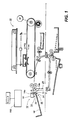
- Fig. 1 is a schematic side view of one example of a duplex copier incorporating the exit roller reversal gate system of the invention;
- Figs. 2 and 3 are otherwise identical perspective views of the exit roller reversal gate portion of the embodiment of Fig. 1, respectively showing the two operating positions of the exemplary exit roller gate mechanism, with respective movement arrows, but with the upper roller set not shown for drawing clarity; and
- Fig. 4 is an enlarged cross-sectional view of the copy sheet exit area of the embodiment of Figs. 1-3, including the exit roller reversal gate portion, with the two operating positions of the exit roller gate respectively shown in solid and phantom lines.
- With reference to the above-noted Figures, there is shown in Fig. 1 a
duplex copier 10 by way of one example of an duplex electrostatographic reproducing machine of a type suitable to utilize the system of the present invention. While themachine 10 is exemplified here as an electrostatographic copier, other types of reproducing machines or apparatus such as laser or ink jet printers, etc., may be envisaged. Although the present system is particularly well adapted for use in such compact copiers or printers, it will be evident from the following description that it is equally well suited for use in a wide variety of reproduction systems and is not limited in application to the particular embodiment shown herein. - The Fig. 1 illustrated
duplex copier 10 per se is that shown and described in the above-cited US-A-4,708,462, and elsewhere, and thus need not be redescribed herein. Thus, the following description relates only to the subject copy sheetoutput path portion 12 of thecopier 10, shown in more detail in Fig. 4 and Figs. 2 & 3. - The subject copy sheet
output path portion 12 particularly includes two mating or nipped sets of copy sheetoutput path rollers 14. Therollers 14 comprise a lower set ofrollers 14b on an axially movable as well asrotatable shaft 15, andupper rollers 14a. One said set of therollers 14 are selectably reversibly driven by areversible drive 16. The other roller set may, conventionally, be idlers. - The
rollers 14 normally continue rotating in one direction to feed and drive the sheets downstream to eject the sheets out of this exit nip to be stacked into output tray 18 (a fixed single tray or or a selected sorter bin), as shown in more detail in Fig. 4. However, for duplexing copy sheets, therollers 14 are reversed while a copy sheet only printed on its first side is still in theroller 14 nip, to transport those copy sheets back into aduplex path 20, for returning those copy sheets to the copy processor with inversion be imaged on their opposite sides to make duplex copies, as shown in Fig. 1. This is taught by the above-cited and other references, particularly the US-A-4,708,462 embodiment disclosed here. To summarize, the sheet reversing for inverting function is integral with the normal exit transport and paper path, implemented by reversal ofrollers 14 and thus reversal of a sheet in the nip thereof. When output of a simplex or fully duplexed copy sheet is desired, therollers 14 simply continue to rotate in the same forward or downstream feeding direction until the sheet is fully ejected from the rollers nip, instead of reversing after only part of the sheet is extending therefrom. - Turning now to the disclosed
system 30 for automatically interposing guide or baffle means to prevent accidental re-acquisition of copy sheets be the reversedrollers 14, this is embodied here by arcuate guide orbaffle fingers 32 mounted topivotal shaft 34 located closely adjacent, slightly under, and parallel to,shaft 15 of the lower set ofrollers 14b. Thefingers 32 are normally spring loaded bytorsion spring 36 into the "up" or first position shown in Fig. 2 (and also shown in phantom or dashed lines in Fig. 4) for normal downstream or forward sheet feeding for ejection and stacking. In this first operating position the arcuate guide orbaffle fingers 32 are substantially inside the radius of the lower set ofrollers 14b, out of normal sheet engagement. - This disclosed embodiment utilizes an exiting axial (side-shifting) movement of the copy
sheet exit rollers 14, serving another purpose, for actuating the automatic interposing of the guide orbaffle system 30 to prevent accidental re-acquisition of copy sheets previously fed from therollers 14 when therollers 14 are reversed. This second operating position of the guide orbaffle fingers 32 is shown in Fig. 3 and also shown in solid lines in Fig. 4. As particularly shown in Fig. 4, in this second operating position of thefingers 32 they are substantially extended outside of the radius of the lower set ofrollers 14b, downward and forward, to push away and hold away the rear edges of previously ejected sheets from thelower rollers 14b, and thus providing an active gate to prevent those sheets already in theexit tray 18 area from being engaged, picked up and fed back into the nip ofrollers 14. That is a particular problem with copy sheets with fluff or curl, which tends to cause their rear edges to engage therollers 14, the surfaces of which are moving upwardly and into the nip when therollers 14 are reversed. With thesystem 30, at least onegate finger 32 is closely operatively associated with eachroller 14b, moving outside of the roller profile when the roller is reversed to shield it. - As shown particularly in Fig. 3,
shaft 15 automatically shifts axially (see the movement arrow) when thereversible drive 16 reverses the direction of drive rotation. This may be accomplished by ahelical coupling 40, or various other conventional, cam or side-shifting mechanisms. As noted above, a similar helix and pin system actuated by roller reversal is disclosed in copending EP Application No. 89 313 566.5. There it is shown shifting the individual rollers, but the same mechanism may be used here at one end of theshaft 15 to shift theshaft 15. Other above-noted examples of sheet lateral (side) shifting or offsetting mechanisms are disclosed in US-A-4,712,786 and US-A-4,480,825. When the rotation of theshaft 15 is reversed, thehelical coupling 40 translates or pulls theshaft 15. Acamming roller 42 onshaft 15 engages an inclinedplane cam follower 44 attached topivotal shaft 36. Thus the axial shifting ofshaft 15 andcamming roller 42 thereon forces downcam follower 44 which causes a corresponding rotation ofshaft 34 and the attached guide orbaffle fingers 32 into the second operating position. This occurs automatically in response to the axial movement of theroller 14 system. - That axial movement of the
reversible roller 14 system is provided for an additional reason and function other than the actuation ofgate system 30. It also provides a de-registration system for duplexing, as per the above-noted copending application. It side-shifts by a small distance (e.g., 3 to 3.5 mm) those copy sheets being reverse fed back into theduplex path 20 so that those sheets may be fed through theduplex path 20 without edge drag, and so that they can subsequently be re-side-registered for the second pass image by side sifting them back in one (known) direction of movement, irrespective of slight misregistrations or skewing in the duplex return path. - As is well known in the art, to control the operation of the
machine 40,m a suitableprogrammable controller 100 and a connecting control panel is preferably conventionally provided. Conventional and/or programmable software microprocessor controls may be used for controlling all machine and paper operations and sensing. - While the embodiment disclosed herein is preferred, it will be appreciated from this teaching that various alternatives, modifications, variations or improvements therein may be made by those skilled in the art, which are intended to be encompassed by the following claims.
Claims (7)
Applications Claiming Priority (2)
| Application Number | Priority Date | Filing Date | Title |
|---|---|---|---|
| US07/398,117 US4916493A (en) | 1989-08-24 | 1989-08-24 | Exit roller reversal gate for duplex printing |
| US398117 | 1989-08-24 |
Publications (3)
| Publication Number | Publication Date |
|---|---|
| EP0414552A2 true EP0414552A2 (en) | 1991-02-27 |
| EP0414552A3 EP0414552A3 (en) | 1991-06-19 |
| EP0414552B1 EP0414552B1 (en) | 1993-12-29 |
Family
ID=23574051
Family Applications (1)
| Application Number | Title | Priority Date | Filing Date |
|---|---|---|---|
| EP90309284A Expired - Lifetime EP0414552B1 (en) | 1989-08-24 | 1990-08-23 | Exit roller reversal gate for duplex printing |
Country Status (4)
| Country | Link |
|---|---|
| US (1) | US4916493A (en) |
| EP (1) | EP0414552B1 (en) |
| JP (1) | JPH0755752B2 (en) |
| DE (1) | DE69005562T2 (en) |
Cited By (1)
| Publication number | Priority date | Publication date | Assignee | Title |
|---|---|---|---|---|
| GB2408019B (en) * | 2002-09-12 | 2005-12-21 | Matsushita Electric Ind Co Ltd | Image forming apparatus |
Families Citing this family (20)
| Publication number | Priority date | Publication date | Assignee | Title |
|---|---|---|---|---|
| US5048724A (en) * | 1988-11-22 | 1991-09-17 | Fedpak Systems, Inc. | Soft serve frozen confection dispenser |
| US5093690A (en) * | 1989-12-06 | 1992-03-03 | Ricoh Company, Ltd. | Paper refeeding device for a copier operable in a two-sided copy mode for refeeding paper sheets from an intermediate tray |
| US5014976A (en) * | 1990-04-04 | 1991-05-14 | Xerox Corporation | Exit roller shield for duplex printing |
| US5058880A (en) * | 1990-08-17 | 1991-10-22 | Xerox Corporation | Disk stacker including wiping member for registration assist |
| WO1993012026A1 (en) * | 1991-12-10 | 1993-06-24 | Fujitsu Limited | Sheet paper conveyor for double-face recording |
| US5273274A (en) * | 1992-09-04 | 1993-12-28 | Xerox Corporation | Sheet feeding system with lateral registration and method for registering sheets |
| US5280901A (en) * | 1993-03-24 | 1994-01-25 | Xerox Corporation | Sheet variable corrugating and feeding nip |
| US5430536A (en) * | 1993-10-12 | 1995-07-04 | Xerox Corporation | Automatic duplex and simplex document handler for electronic input |
| US5549292A (en) * | 1994-10-31 | 1996-08-27 | Xerox Corporation | Sheet stacking and reversing separator |
| US5486911A (en) * | 1994-12-08 | 1996-01-23 | Xerox Corporation | Document handler for imaging system with plural mode output tray |
| JPH10203692A (en) * | 1997-01-17 | 1998-08-04 | Mita Ind Co Ltd | Automatic document conveyer |
| US6103985A (en) * | 1997-08-04 | 2000-08-15 | Unisys Corporation | Turn around loop apparatus for document scanning/processing |
| US6186496B1 (en) | 1998-08-31 | 2001-02-13 | Xerox Corporation | Optimized passive gate inverter |
| US6334042B1 (en) | 2000-11-28 | 2001-12-25 | Xerox Corporation | Side shifting cleaning apparatus and method |
| JP4846651B2 (en) * | 2007-05-01 | 2011-12-28 | 株式会社リコー | Paper discharge device and image forming apparatus |
| US7866661B2 (en) * | 2007-08-29 | 2011-01-11 | Pitney Bowes Inc. | Sheet/page buffer for sheet handling apparatus |
| JP4510899B2 (en) * | 2008-01-11 | 2010-07-28 | シャープ株式会社 | Sheet conveying apparatus, document processing apparatus and image forming apparatus using the same |
| JP2012171779A (en) * | 2011-02-24 | 2012-09-10 | Seiko Epson Corp | Medium discharge device |
| CN105293149A (en) * | 2015-11-26 | 2016-02-03 | 倪煌斌 | Conveying table for collected paper piles |
| JP6972817B2 (en) * | 2017-09-14 | 2021-11-24 | 京セラドキュメントソリューションズ株式会社 | Sheet transfer device, image reader, image forming device |
Citations (1)
| Publication number | Priority date | Publication date | Assignee | Title |
|---|---|---|---|---|
| US4708462A (en) * | 1985-12-30 | 1987-11-24 | Xerox Corporation | Auto duplex reproduction machine |
Family Cites Families (12)
| Publication number | Priority date | Publication date | Assignee | Title |
|---|---|---|---|---|
| US3108801A (en) * | 1960-06-28 | 1963-10-29 | Nederlanden Staat | Device for conducting postal articles, forms or the like |
| US3173684A (en) * | 1962-10-31 | 1965-03-16 | Sperry Rand Corp | Document feeder |
| DE2522264C3 (en) * | 1975-05-20 | 1982-05-06 | Canon K.K., Tokyo | Projection copier |
| JPS52142517A (en) * | 1976-05-21 | 1977-11-28 | Canon Inc | Control device for copying machine |
| US4493483A (en) * | 1979-01-31 | 1985-01-15 | Xerox Corporation | Inverter-reverser for a reproduction machine |
| US4348101A (en) * | 1980-09-30 | 1982-09-07 | Sperry Corporation | Duplex printing apparatus |
| US4508444A (en) * | 1982-08-02 | 1985-04-02 | Xerox Corporation | Multimode document handling apparatus and reproducing apparatus containing same |
| US4494747A (en) * | 1983-07-01 | 1985-01-22 | Diebold, Incorporated | Paper currency dispenser friction picker mechanism |
| DK152315C (en) * | 1984-10-25 | 1988-07-11 | Hans Christian Hyltoft | ELECTROPOTOGRAPHIC INFORMATION PRINTER WITH AUTOMATIC DOUBLE SIDE PRINTING |
| US4787616A (en) * | 1984-10-26 | 1988-11-29 | Canon Kabushiki Kaisha | Sheet stacking device and image forming apparatus provided with same |
| JPS6188956U (en) * | 1984-11-17 | 1986-06-10 | ||
| US4727401A (en) * | 1986-09-26 | 1988-02-23 | Xerox Corporation | Two-up automatic document feeder for simplex to duplex copying |
-
1989
- 1989-08-24 US US07/398,117 patent/US4916493A/en not_active Expired - Lifetime
-
1990
- 1990-08-17 JP JP2217999A patent/JPH0755752B2/en not_active Expired - Fee Related
- 1990-08-23 DE DE69005562T patent/DE69005562T2/en not_active Expired - Fee Related
- 1990-08-23 EP EP90309284A patent/EP0414552B1/en not_active Expired - Lifetime
Patent Citations (1)
| Publication number | Priority date | Publication date | Assignee | Title |
|---|---|---|---|---|
| US4708462A (en) * | 1985-12-30 | 1987-11-24 | Xerox Corporation | Auto duplex reproduction machine |
Cited By (2)
| Publication number | Priority date | Publication date | Assignee | Title |
|---|---|---|---|---|
| GB2408019B (en) * | 2002-09-12 | 2005-12-21 | Matsushita Electric Ind Co Ltd | Image forming apparatus |
| US6983122B2 (en) | 2002-09-12 | 2006-01-03 | Matsushita Electric Industrial Co., Ltd. | Image forming apparatus |
Also Published As
| Publication number | Publication date |
|---|---|
| JPH0755752B2 (en) | 1995-06-14 |
| EP0414552A3 (en) | 1991-06-19 |
| DE69005562T2 (en) | 1994-05-26 |
| EP0414552B1 (en) | 1993-12-29 |
| US4916493A (en) | 1990-04-10 |
| DE69005562D1 (en) | 1994-02-10 |
| JPH03122674A (en) | 1991-05-24 |
Similar Documents
| Publication | Publication Date | Title |
|---|---|---|
| EP0414552B1 (en) | Exit roller reversal gate for duplex printing | |
| US5351112A (en) | Original feeding apparatus and image forming system with it | |
| US6168153B1 (en) | Printer sheet deskewing system with automatically variable numbers of upstream feeding NIP engagements for different sheet sizes | |
| US5014976A (en) | Exit roller shield for duplex printing | |
| EP0623857B1 (en) | Print skip avoidance for on-line compiling | |
| US6173952B1 (en) | Printer sheet deskewing system with automatic variable nip lateral spacing for different sheet sizes | |
| US6038424A (en) | Sheet conveying apparatus and image forming apparatus provided with the same | |
| JP4516894B2 (en) | Automatic document feeder, image forming apparatus having the same, and image reading apparatus | |
| US6817609B2 (en) | Printer sheet lateral registration system with automatic upstream nip disengagements for different sheet size | |
| JPH0313463A (en) | Image forming device having paper refeed and carrying path | |
| US6042098A (en) | Sheet post-processing apparatus | |
| JPS6337069A (en) | Sheet stacker | |
| JP3002216B2 (en) | Double-sided image forming method and apparatus | |
| JP2954630B2 (en) | Double-sided image forming method | |
| JP3695231B2 (en) | Image forming system | |
| JPH10218432A (en) | Paper sheet carrying device | |
| JP2523559B2 (en) | Paper transport method and apparatus for recording apparatus | |
| JPH10218503A (en) | Document feeder | |
| JP3221082B2 (en) | Double-sided image forming device | |
| JP3795488B2 (en) | Image forming apparatus | |
| JP4289739B2 (en) | Image forming apparatus | |
| JPH07121782B2 (en) | Paper reversing device for copier | |
| JPH11349187A (en) | Sheet separation device and picture image formation device | |
| JPH0423779A (en) | Device for neatly arranging sheet width in sheet carrying device | |
| JPH03126959A (en) | Image forming device |
Legal Events
| Date | Code | Title | Description |
|---|---|---|---|
| PUAI | Public reference made under article 153(3) epc to a published international application that has entered the european phase |
Free format text: ORIGINAL CODE: 0009012 |
|
| AK | Designated contracting states |
Kind code of ref document: A2 Designated state(s): DE FR GB |
|
| PUAL | Search report despatched |
Free format text: ORIGINAL CODE: 0009013 |
|
| AK | Designated contracting states |
Kind code of ref document: A3 Designated state(s): DE FR GB |
|
| 17P | Request for examination filed |
Effective date: 19911204 |
|
| 17Q | First examination report despatched |
Effective date: 19930224 |
|
| GRAA | (expected) grant |
Free format text: ORIGINAL CODE: 0009210 |
|
| AK | Designated contracting states |
Kind code of ref document: B1 Designated state(s): DE FR GB |
|
| REF | Corresponds to: |
Ref document number: 69005562 Country of ref document: DE Date of ref document: 19940210 |
|
| ET | Fr: translation filed | ||
| PLBE | No opposition filed within time limit |
Free format text: ORIGINAL CODE: 0009261 |
|
| STAA | Information on the status of an ep patent application or granted ep patent |
Free format text: STATUS: NO OPPOSITION FILED WITHIN TIME LIMIT |
|
| 26N | No opposition filed | ||
| REG | Reference to a national code |
Ref country code: GB Ref legal event code: IF02 |
|
| REG | Reference to a national code |
Ref country code: GB Ref legal event code: 746 Effective date: 20050512 |
|
| PGFP | Annual fee paid to national office [announced via postgrant information from national office to epo] |
Ref country code: FR Payment date: 20050809 Year of fee payment: 16 |
|
| PGFP | Annual fee paid to national office [announced via postgrant information from national office to epo] |
Ref country code: DE Payment date: 20060817 Year of fee payment: 17 |
|
| PGFP | Annual fee paid to national office [announced via postgrant information from national office to epo] |
Ref country code: GB Payment date: 20060823 Year of fee payment: 17 |
|
| REG | Reference to a national code |
Ref country code: FR Ref legal event code: ST Effective date: 20070430 |
|
| GBPC | Gb: european patent ceased through non-payment of renewal fee |
Effective date: 20070823 |
|
| PG25 | Lapsed in a contracting state [announced via postgrant information from national office to epo] |
Ref country code: FR Free format text: LAPSE BECAUSE OF NON-PAYMENT OF DUE FEES Effective date: 20060831 |
|
| PG25 | Lapsed in a contracting state [announced via postgrant information from national office to epo] |
Ref country code: DE Free format text: LAPSE BECAUSE OF NON-PAYMENT OF DUE FEES Effective date: 20080301 |
|
| PG25 | Lapsed in a contracting state [announced via postgrant information from national office to epo] |
Ref country code: GB Free format text: LAPSE BECAUSE OF NON-PAYMENT OF DUE FEES Effective date: 20070823 |