EP0418773A2 - Dimensionally stable laminate, its use, and method of manufacture - Google Patents
Dimensionally stable laminate, its use, and method of manufacture Download PDFInfo
- Publication number
- EP0418773A2 EP0418773A2 EP90117828A EP90117828A EP0418773A2 EP 0418773 A2 EP0418773 A2 EP 0418773A2 EP 90117828 A EP90117828 A EP 90117828A EP 90117828 A EP90117828 A EP 90117828A EP 0418773 A2 EP0418773 A2 EP 0418773A2
- Authority
- EP
- European Patent Office
- Prior art keywords
- composite body
- perforated
- dimensionally stable
- perforations
- body according
- Prior art date
- Legal status (The legal status is an assumption and is not a legal conclusion. Google has not performed a legal analysis and makes no representation as to the accuracy of the status listed.)
- Withdrawn
Links
Images


Classifications
-
- B—PERFORMING OPERATIONS; TRANSPORTING
- B32—LAYERED PRODUCTS
- B32B—LAYERED PRODUCTS, i.e. PRODUCTS BUILT-UP OF STRATA OF FLAT OR NON-FLAT, e.g. CELLULAR OR HONEYCOMB, FORM
- B32B3/00—Layered products comprising a layer with external or internal discontinuities or unevennesses, or a layer of non-planar form; Layered products having particular features of form
- B32B3/26—Layered products comprising a layer with external or internal discontinuities or unevennesses, or a layer of non-planar form; Layered products having particular features of form characterised by a particular shape of the outline of the cross-section of a continuous layer; characterised by a layer with cavities or internal voids ; characterised by an apertured layer
- B32B3/266—Layered products comprising a layer with external or internal discontinuities or unevennesses, or a layer of non-planar form; Layered products having particular features of form characterised by a particular shape of the outline of the cross-section of a continuous layer; characterised by a layer with cavities or internal voids ; characterised by an apertured layer characterised by an apertured layer, the apertures going through the whole thickness of the layer, e.g. expanded metal, perforated layer, slit layer regular cells B32B3/12
-
- B—PERFORMING OPERATIONS; TRANSPORTING
- B32—LAYERED PRODUCTS
- B32B—LAYERED PRODUCTS, i.e. PRODUCTS BUILT-UP OF STRATA OF FLAT OR NON-FLAT, e.g. CELLULAR OR HONEYCOMB, FORM
- B32B27/00—Layered products comprising a layer of synthetic resin
- B32B27/06—Layered products comprising a layer of synthetic resin as the main or only constituent of a layer, which is next to another layer of the same or of a different material
- B32B27/08—Layered products comprising a layer of synthetic resin as the main or only constituent of a layer, which is next to another layer of the same or of a different material of synthetic resin
-
- C—CHEMISTRY; METALLURGY
- C09—DYES; PAINTS; POLISHES; NATURAL RESINS; ADHESIVES; COMPOSITIONS NOT OTHERWISE PROVIDED FOR; APPLICATIONS OF MATERIALS NOT OTHERWISE PROVIDED FOR
- C09J—ADHESIVES; NON-MECHANICAL ASPECTS OF ADHESIVE PROCESSES IN GENERAL; ADHESIVE PROCESSES NOT PROVIDED FOR ELSEWHERE; USE OF MATERIALS AS ADHESIVES
- C09J7/00—Adhesives in the form of films or foils
- C09J7/20—Adhesives in the form of films or foils characterised by their carriers
- C09J7/22—Plastics; Metallised plastics
-
- C—CHEMISTRY; METALLURGY
- C09—DYES; PAINTS; POLISHES; NATURAL RESINS; ADHESIVES; COMPOSITIONS NOT OTHERWISE PROVIDED FOR; APPLICATIONS OF MATERIALS NOT OTHERWISE PROVIDED FOR
- C09J—ADHESIVES; NON-MECHANICAL ASPECTS OF ADHESIVE PROCESSES IN GENERAL; ADHESIVE PROCESSES NOT PROVIDED FOR ELSEWHERE; USE OF MATERIALS AS ADHESIVES
- C09J7/00—Adhesives in the form of films or foils
- C09J7/20—Adhesives in the form of films or foils characterised by their carriers
- C09J7/29—Laminated material
-
- C—CHEMISTRY; METALLURGY
- C09—DYES; PAINTS; POLISHES; NATURAL RESINS; ADHESIVES; COMPOSITIONS NOT OTHERWISE PROVIDED FOR; APPLICATIONS OF MATERIALS NOT OTHERWISE PROVIDED FOR
- C09J—ADHESIVES; NON-MECHANICAL ASPECTS OF ADHESIVE PROCESSES IN GENERAL; ADHESIVE PROCESSES NOT PROVIDED FOR ELSEWHERE; USE OF MATERIALS AS ADHESIVES
- C09J7/00—Adhesives in the form of films or foils
- C09J7/30—Adhesives in the form of films or foils characterised by the adhesive composition
- C09J7/35—Heat-activated
-
- F—MECHANICAL ENGINEERING; LIGHTING; HEATING; WEAPONS; BLASTING
- F41—WEAPONS
- F41H—ARMOUR; ARMOURED TURRETS; ARMOURED OR ARMED VEHICLES; MEANS OF ATTACK OR DEFENCE, e.g. CAMOUFLAGE, IN GENERAL
- F41H5/00—Armour; Armour plates
- F41H5/02—Plate construction
- F41H5/023—Armour plate, or auxiliary armour plate mounted at a distance of the main armour plate, having cavities at its outer impact surface, or holes, for deflecting the projectile
-
- F—MECHANICAL ENGINEERING; LIGHTING; HEATING; WEAPONS; BLASTING
- F41—WEAPONS
- F41H—ARMOUR; ARMOURED TURRETS; ARMOURED OR ARMED VEHICLES; MEANS OF ATTACK OR DEFENCE, e.g. CAMOUFLAGE, IN GENERAL
- F41H5/00—Armour; Armour plates
- F41H5/02—Plate construction
- F41H5/04—Plate construction composed of more than one layer
- F41H5/0471—Layered armour containing fibre- or fabric-reinforced layers
- F41H5/0478—Fibre- or fabric-reinforced layers in combination with plastics layers
-
- B—PERFORMING OPERATIONS; TRANSPORTING
- B32—LAYERED PRODUCTS
- B32B—LAYERED PRODUCTS, i.e. PRODUCTS BUILT-UP OF STRATA OF FLAT OR NON-FLAT, e.g. CELLULAR OR HONEYCOMB, FORM
- B32B2305/00—Condition, form or state of the layers or laminate
- B32B2305/02—Cellular or porous
- B32B2305/026—Porous
-
- B—PERFORMING OPERATIONS; TRANSPORTING
- B32—LAYERED PRODUCTS
- B32B—LAYERED PRODUCTS, i.e. PRODUCTS BUILT-UP OF STRATA OF FLAT OR NON-FLAT, e.g. CELLULAR OR HONEYCOMB, FORM
- B32B2307/00—Properties of the layers or laminate
- B32B2307/50—Properties of the layers or laminate having particular mechanical properties
- B32B2307/514—Oriented
-
- B—PERFORMING OPERATIONS; TRANSPORTING
- B32—LAYERED PRODUCTS
- B32B—LAYERED PRODUCTS, i.e. PRODUCTS BUILT-UP OF STRATA OF FLAT OR NON-FLAT, e.g. CELLULAR OR HONEYCOMB, FORM
- B32B2307/00—Properties of the layers or laminate
- B32B2307/70—Other properties
- B32B2307/732—Dimensional properties
- B32B2307/734—Dimensional stability
-
- C—CHEMISTRY; METALLURGY
- C09—DYES; PAINTS; POLISHES; NATURAL RESINS; ADHESIVES; COMPOSITIONS NOT OTHERWISE PROVIDED FOR; APPLICATIONS OF MATERIALS NOT OTHERWISE PROVIDED FOR
- C09J—ADHESIVES; NON-MECHANICAL ASPECTS OF ADHESIVE PROCESSES IN GENERAL; ADHESIVE PROCESSES NOT PROVIDED FOR ELSEWHERE; USE OF MATERIALS AS ADHESIVES
- C09J2301/00—Additional features of adhesives in the form of films or foils
- C09J2301/10—Additional features of adhesives in the form of films or foils characterized by the structural features of the adhesive tape or sheet
- C09J2301/16—Additional features of adhesives in the form of films or foils characterized by the structural features of the adhesive tape or sheet by the structure of the carrier layer
- C09J2301/162—Additional features of adhesives in the form of films or foils characterized by the structural features of the adhesive tape or sheet by the structure of the carrier layer the carrier being a laminate constituted by plastic layers only
Definitions
- the invention relates to a dimensionally stable composite body in the form of a flat or curved plate, from a number of layered, pressed together, thermoplastic plastic films, which are coated on at least one side with a sealing layer, the melting point of which is lower than the melting point of each of the plastic films and the mono- and / or biaxially stretched, a process for its production and its use.
- thermosetting and thermoplastic polymer materials the mechanical properties of which are improved many times over the unreinforced polymer by incorporating reinforcing materials in the form of textile, glass, carbon or aramid fibers.
- a process-specific measure of this technique namely the use of individual film layers, enables the targeted installation of functional layers at any point on the shaped body and thus the tailoring of properties of the finished shaped body.
- biaxially stretched films can be combined with monoaxial or undrawn films of the same or a different type in order to influence the fracture-mechanical behavior of the molded article in the desired manner.
- the product characteristics achieved in this way are often not sufficient to meet the extreme mechanical requirements of highly stressed materials in practice.
- AT-PS 383 542 is a rigid molded body, such as a plate or a tube, from a plurality of stacked and / or juxtaposed and pressed together, oriented, ie stretched, thermoplastic plastic carrier in film, ribbon, monofilament or fiber form described.
- the stretched plastic carriers on the sides that come into contact with the layers on top of and / or next to one another are coated with thermoplastic, the coating material having a lower crystallite melting temperature than the plastic carriers and the thickness of two adjacent coating dimensions materials is less than the thickness of a plastic carrier.
- the method proposed in the Austrian patent specification AT-PS 383 542 provides high-strength, mechanically stable plates by applying pressure to stretched, coextruded thin plastic films, under the action of heat, the plastic carriers coated on the mutual contact surfaces with thermoplastic plastic at a temperature above the crystallite melting temperature of the Coating material and below the crystallite melting temperature of the plastic carrier are pressed.
- the basic principle of this process compared to alternative plate-making technologies, such as extrusion, casting and calendering, offers the possibility of preventing a noteworthy drop in the mechanical and physical properties achieved by stretching a single plastic carrier by pressing at elevated temperature, so that the molded body , despite its larger dimensions, which substantially exceed the dimensions of the individual plastic carrier, approximately has the mechanical and technological properties of an individual stretched plastic carrier.
- targeted functional layers can either be applied to the surface of the plate or in the form of intermediate layers in the type and structure of the films used Plate are inserted, and on the other hand, corresponding surface structures can be created by selecting suitable press dies.
- the object of the present invention is to develop a dimensionally stable composite body of the type described at the outset into a mechanically high-strength, flexurally rigid, but at the same time, lightweight, composite body.
- This object is achieved in that at least some of the plastic films forming the composite have perforations and that the perforated plastic films are layered one on top of the other in such a way that their perforations overlap or are offset from one another.
- they are the composite body-forming plastic films on the one hand full-surface, homogeneous plastic films without perforations and on the other hand perforated plastic films in a geometrical arrangement, and the perforated and full-surface plastic films are alternately layered so that the perforations are offset from one another.
- the composite body is formed by pressing perforated laminates, each laminate having a thickness of up to 1 mm and consisting of several perforated plastic films.
- the composite body is formed by pressing perforated plastic plates a few millimeters thick, and the individual plastic plate consists of a plurality of laminates pressed in perforated form. It is thus possible for the composite body to be formed by pressing perforated plastic plates a few millimeters thick and for the individual plastic plate to consist of laminates which are only perforated after lamination.
- the composite body expediently consists of at least one perforated plastic plate which is embedded between two non-perforated cover plates.
- the composite body can consist of a plurality of perforated plastic plates which are embedded between two non-perforated cover plates, the perforations being offset from one another to the plastic plate.
- the plastic films are perforated before the pressing, which are layered after the perforation to form a stack of films, the perforations of all plastic films being aligned and / or alternating are offset against each other, and the film stack is finally pressed into an inseparable composite body using heat.
- the composite body is used as a breakthrough and bullet-resistant shielding material in the security field, as a light, high-strength construction element in machine and apparatus construction, in vehicle, automobile and aircraft construction, as a wall, formwork, support and drainage element in deep , Tunnel and high construction and as a decorative cladding component in facade, exhibition stand and interior construction.
- a composite body according to the invention has practically no impairment of its strength properties, but has a reduced weight due to the perforations.
- the mechanical properties of the finished composite body can be specifically determined and at the same time weight reductions of a maximum of 50 to 60% compared to a composite body made of solid material can be realized.
- biaxially stretched films made of polypropylene and polyester are used to produce the composite body.
- These foils are characterized by a low purchase price and, as a result of the biaxial orientation, have high mechanical strength.
- a composite body made from it is an inexpensive semi-finished construction product. The emphasis on polypropylene and polyester films as the base material of the composite body in no way precludes other suitable polymer materials or polymer combinations as the starting material for the composite body.
- the first embodiment according to Figures 1 and 2 represents a simple embodiment of a composite body 1 in the form of a homogeneous, flat plate, which consists of a number of thin, mono- and / or biaxially stretched, coextruded plastic films 5 ', 5 ⁇ , 5 ′′′ outer sealing layers 10 was assembled under pressure and temperature.
- the two outer, full-surface cover films 6 include the plastic films 5 ', 5 ⁇ , 5 ′′′, which form the total thickness of the composite body 1.
- the plastic films 5 ', 5 ⁇ , 5 ′′′ have perforations 7', 7 ⁇ , 7 ′′′ in the form of any shaped recesses. In the example according to FIG. 1, they are shown as round holes.
- FIG. 1 In the plan view of Fig. 1 show the perforations 7 ', which are drawn with full lines that there are recesses in the top plastic film 5'.
- the perforations 7 ⁇ in the underlying plastic film 5 ⁇ are shown in dashed lines, while the perforations 7 ′′′ in the third plastic film 5 ′′′ from above (see FIG. 2) with the perforations 7 'of the top plastic film to cover and therefore in the Top view of FIG. 1 are not recognizable.
- Each of the plastic films 5 ', 5 ⁇ , 5 ′′′ ... carries at least one sealing layer 10, which during the thermal Compression of the composite body melts, the melt filling the perforations 7 ', 7 ⁇ , 7 ′′′ ... and after cooling produces an inseparable bond between the individual plastic films.
- An alternate layering of perforated plastic films 5 ', 5 ⁇ , 5 ′′′ ... with full-area films 5 has the second embodiment of the composite body 1 shown in Fig. 3.
- the stack of perforated and full-area films 5 ', 5 ⁇ 5 ′′′ and 5 is enclosed by cover films 6, which have a greater thickness than the films of the stack.
- the perforations 7 'and 7 ⁇ or 7 ⁇ and 7 ′′′ are congruent or offset from each other.
- the cover films 6 are both structured in relief, but it is obvious that both can also be smooth or only the upper or only the lower cover film can be smooth.
- the third embodiment of the composite body 1 according to FIGS. 4 and 5 differs from the exemplary embodiments according to FIGS. 1 to 3 in that the stratification of the individual plastic films 5 ', 5 ⁇ , 5 ′′′ takes place in such a way that the perforations 7', 7 ⁇ , 7 ′′′ cover.
- This geometric arrangement results in a composite body in the form of a heavy-duty perforated plate with open cross sections.
- the exemplary embodiments of the composite body shown in FIGS. 1 to 5 are produced from thin, stretched foils in the thickness range from 10 to 500 ⁇ m, the production of the composite body in the same way is of course also possible from much thicker laminates.
- the thin plastic films 5 ', 5 ⁇ , 5 ′′′ or 5 are replaced by laminates 2', 2 ⁇ , 2 ′′′ or 2 lying in the thickness range of several millimeters, which are made in a preliminary stage in an identical manner to the composite body the film single cell layers are thermally braced. It is irrelevant for the end result whether the perforations are already punched into the individual foils intended for the production of the laminate or only afterwards in the fully pressed laminate.
- the laminates are indicated by parenthesized reference numbers 2 ', 2 ⁇ , 2 ′′′ and 2.
- the fourth embodiment of the invention shown in FIG. 6 has an increased axial moment of inertia of the composite body 1 against bending stress, by increasing the thickness of the resilient cross-section while minimizing the weight increase due to the increased thickness of the composite body 1. This is achieved by combining the two cover plates 4 with a high-strength spacer plate 13 having cutouts 12 and thus significantly reduced in weight , which is equipped on the top and bottom with a sealing layer 10.
- the composite body 1 can be produced in one operation either by pressing appropriately layered, full-surface or already perforated film layers, or by combining the laminates pressed and perforated from individual films in separate individual steps.
- the fifth embodiment of the composite body 1 shown in Figure 7 has a plurality of thin perforated plastic plates 9 ', 9 ⁇ , 9 ′′′ between the two cover plates 4.
- This concept enables the tailoring of composite bodies tailored to the load or the respective area of application.
- the thickness and number of plastic plates and their arrangement in the layer composite for example varying the plate thickness from the inside out, can be changed.
- the properties of the finished composite body can be influenced by the choice of the perforation geometry, that is to say the cross-sectional size, shape and hole division of each individual plate, and the geometric arrangement of the perforations in the overall composite.
- FIG. 8 shows a sixth embodiment of the composite body 1.
- perforated plastic plates 9 ', 9 ⁇ and 9 ⁇ , 9 ′′′ additional full-surface plastic plates 9 installed.
- This sandwich construction lends itself to the combination of panels made of different materials, whereby in addition to polymeric materials in non-reinforced form, also through materials such as glass, textile, metal or carbon fibers, also through metal sheets or metal mesh or textiles made of natural or synthetic materials Fiber reinforced, polymeric materials come into consideration. It is necessary to install suitable adhesion promoters or adhesive layers for the connection of different materials.
- Both cover plates 4 are structured in relief, but only one cover plate can be structured, while the other cover plate is smooth.
- the seventh embodiment shown in FIG. 9 differs from this in that it has a perforated surface.
- the composite body 1 is composed of plastic plates 14 ', 14 ⁇ , ... 14 iv with perforations 15', 15 ⁇ ... 15 iv , which have different diameters or dimensions and are mutually offset so that the perforations of the plastic sheets stacked one on top of the other overlap in spite of mutual displacement, and are connected to one another when viewed in the direction of the sheet thickness, ie form open cross sections.
- layers of the plastic plates are also possible in which the offset of the perforations leads to closed cross sections. 9 shows the sealing layers 10 on the individual plastic plates.
- perforated plastic plates 14 ', 14' consisting of different polymers with such perforated plates 14, the perforations 15 of which are made of different materials 16, 16 ', 16'. .. are filled out, extensive options for property modification of the composite body.
- perforations of the plates 14 for example die-cuts made of polymers, metals, natural or synthetic textiles, glass, ceramics, wood, leather, natural or synthetic rubbers corresponding to the perforation shape can be used.
- Shaped bodies in the form of spheres for example made of metal, or mineral materials, such as glass or ceramic, and platelets, for example, also come out as filler material Mica, or granules, such as polymer granules, into consideration.
- the perforations can also be filled with powders and dusts of any kind. If liquids are used whose evaporation temperature is above the pressing temperature, these materials can also be used.
- reactive media such as foamable products, the reaction mechanism of which is triggered either when the molded body is manufactured or only when it is subjected to a specific load, for example thermal stress in the event of fire, or air contact in the event of mechanical damage to the composite body.
- the installation of reactive components results in plates with a so-called “self-healing effect", ie reactions of released products on damaged areas of the composite body cause the local defect to be closed.
- Thermoplastic plastic films with at least one heat seal layer are suitable for producing the multilayer composite bodies.
- Films made of thermoplastics from the group of polyesters and polyolefins are particularly suitable.
- Polyester is to be understood as meaning polyester homopolymers and copolymers, mixtures of different polyesters and mixtures of polyesters with other polymers.
- propylene homopolymers or copolymers are used as polyesters, the latter being predominantly composed of propylene units.
- the coatings which are usually used for this purpose in film production can be used as heat-sealing layers. These are preferably statistical copolymers of ethylene-propylene units and copolyesters containing ethylene terephthalate and isophthalate units. Furthermore, ethylene-vinyl acetate copolymers, polyurethanes, polyvinyl butyral, acrylate copolymers and copolyamides are suitable as sealing or adhesion promoter layers.
- films of the type described above have a thickness in the range from 10 to 300 ⁇ m, in particular from 40 to 200 ⁇ m.
- the thickness of the heat seal layer, which is applied to the plastic film or the plastic plate on one or both sides, usually does not exceed 10% of the thickness of the carrier film and is in the range from 0.5 to 5 ⁇ m.
- the starting material for producing the composite body In addition to the laminates described, pressed from a number of plastic films in a separate step, several mm thick, stiff plastic plates that are already pressed from the laminates are suitable as the starting material for producing the composite body.
- the perforations can either be made in the starting foils or can be made afterwards on the laminates or plastic plates by punching.
- Construction elements with high mechanical strength and the lowest possible weight are aimed for.
- the labyrinthine structure of the composite body makes it particularly suitable for use as a breakthrough and bullet-resistant shielding material.
- Composite bodies can be used for drainage systems in road, tunnel and civil engineering. It can also be used as a screen and noise shield with reduced wind loads.
Landscapes
- Chemical & Material Sciences (AREA)
- Organic Chemistry (AREA)
- Engineering & Computer Science (AREA)
- General Engineering & Computer Science (AREA)
- Ceramic Engineering (AREA)
- Laminated Bodies (AREA)
Abstract
Description
Die Erfindung betrifft einen dimensionsstabilen Verbundkörper in Gestalt einer ebenen oder gekrümmten Platte, aus einer Anzahl übereinander geschichteter, miteinander verpreßter, thermoplastischer Kunststoffolien, die zumindest einseitig mit einer Siegelschicht beschichtet sind, deren Schmelzpunkt niedriger als der Schmelzpunkt jeder der Kunststoffolien ist und die mono- und/oder biaxial verstreckt sind, ein Verfahren zu seiner Herstellung und seine Verwendung.The invention relates to a dimensionally stable composite body in the form of a flat or curved plate, from a number of layered, pressed together, thermoplastic plastic films, which are coated on at least one side with a sealing layer, the melting point of which is lower than the melting point of each of the plastic films and the mono- and / or biaxially stretched, a process for its production and its use.
In den letzten Jahren ist seitens verschiedener Branchen, wie z.B. dem Fahrzeugbau, Flugzeugbau, Apparatebau, ein verstärkter Trend zum Einsatz von Hochleistungsverbundwerkstoffen zu beobachten. Hierunter einzuordnen sind u.a. duroplastische und thermoplastische Polymerwerkstoffe, deren mechanische Eigenschaften durch Einarbeitung von Verstärkungsmaterialien in Form von Textil-, Glas-, Kohlenstoff- oder Aramidfasern um ein Vielfaches gegenüber dem unverstärkten Polymeren verbessert werden.In recent years, various industries, such as vehicle construction, aircraft construction, apparatus construction, an increasing trend towards the use of high-performance composite materials can be observed. These include: thermosetting and thermoplastic polymer materials, the mechanical properties of which are improved many times over the unreinforced polymer by incorporating reinforcing materials in the form of textile, glass, carbon or aramid fibers.
Alternativ zu dem Einarbeiten von Verstärkungsmaterialien wurden Techniken entwickelt, hochfeste Kunststoffplatten durch Orientierungsprozesse herzustellen. Als eine Technik im Rahmen der Orientierungsprozesse kann das in der EP-A1 - 0 207 047 beschriebene Verfahren gelten, bei dem eine Vielzahl biaxial verstreckter, mit dünnen koextrudierten Siegelschichten ausgerüsteter Folien zu einer dicken, homogenen Platte unter Druck und Temperatur verpreßt werden.As an alternative to the incorporation of reinforcement materials, techniques have been developed to produce high-strength plastic plates using orientation processes. The technique described in EP-A1-0 207 047, in which a multiplicity of biaxially oriented, with thin co-extruded sealing layers of finished films can be pressed to form a thick, homogeneous plate under pressure and temperature.
Eine verfahrensspezifische Maßnahme dieser Technik, nämlich die Verwendung einzelner Folienlagen, ermöglicht den gezielten Einbau von Funktionsschichten an beliebiger Stelle des Formkörpers und damit die Maßschneiderei von Eigenschaften des fertigen Formkörpers. So können beispielsweise biaxial verstreckte Folien mit monoaxial oder unverstreckten artgleichen oder artfremden Folien kombiniert werden, um das bruchmechanische Verhalten des Formkörpers in gewünschter Weise zu beeinflussen. Die auf diese Weise erzielten Produkteigenschaften reichen vielfach aber nicht aus, um den extremen mechanischen Anforderungen hochbeanspruchter Materialien in der Praxis gerecht zu werden.A process-specific measure of this technique, namely the use of individual film layers, enables the targeted installation of functional layers at any point on the shaped body and thus the tailoring of properties of the finished shaped body. For example, biaxially stretched films can be combined with monoaxial or undrawn films of the same or a different type in order to influence the fracture-mechanical behavior of the molded article in the desired manner. The product characteristics achieved in this way are often not sufficient to meet the extreme mechanical requirements of highly stressed materials in practice.
In der AT-PS 383 542 ist ein steifer Formkörper, wie eine Platte oder ein Rohr, aus einer Vielzahl übereinander und/oder nebeneinander geschichteter und miteinander verpreßter, orientierter, d.h. verstreckter, thermoplastischer Kunststoffträger in Folien-, Bändchen-, Monofil- oder Faserform beschrieben. Die verstreckten Kunststoffträger an den beim Über- und/oder Nebeneinanderschichten zur Anlage gelangenden Seiten sind mit thermoplastischem Kunststoff beschichtet, wobei das Beschichtungsmaterial eine niedrigere Kristallitschmelztemperatur aufweist als die Kunststoffträger und die Dicke von je zwei aneinanderliegenden Beschichtungsma terialien geringer ist als die Dicke eines Kunststoffträgers.In AT-PS 383 542 is a rigid molded body, such as a plate or a tube, from a plurality of stacked and / or juxtaposed and pressed together, oriented, ie stretched, thermoplastic plastic carrier in film, ribbon, monofilament or fiber form described. The stretched plastic carriers on the sides that come into contact with the layers on top of and / or next to one another are coated with thermoplastic, the coating material having a lower crystallite melting temperature than the plastic carriers and the thickness of two adjacent coating dimensions materials is less than the thickness of a plastic carrier.
Das in der österreichischen Patentschrift AT-PS 383 542 vorgeschlagene Verfahren liefert hochfeste, mechanisch stabile Platten durch Druckanwendung auf verstreckte, koextrudierte dünne Kunststoffolien, unter Einwirkung von Wärme, wobei die an den gegenseitigen Berührungsflächen mit thermoplastischem Kunststoff beschichteten Kunststoffträger bei einer Temperatur oberhalb der Kristallitschmelztemperatur des Beschichtungsmaterials und unterhalb der Kristallitschmelztemperatur des Kunststoffträgers verpreßt werden. Dieses Verfahren bietet von seinem Grundprinzip her gegenüber alternativen Plattenherstelltechnologien, wie z.B. Extrusion, Gießen und Kalandrieren, die Möglichkeit, durch Verpressen bei erhöhter Temperatur einen nennenswerten Abfall der durch das Verstrecken eines einzelnen Kunststoffträgers erzielten günstigen mechanischen und physikalischen Eigenschaften zu verhindern, so daß der Formkörper, trotz seiner größeren, die Abmessungen des einzelnen Kunststoffträgers wesentlich überschreitenden Dimensionen näherungsweise die mechanischen und technologischen Eigenschaften eines einzelnen verstreckten Kunststoffträgers aufweist. Da ein Folienstapel aus einzelnen, gleichartigen oder unterschiedlichen Folien beliebig geschichtet und gepreßt wird, können einerseits über die Art und den Aufbau der verwendeten Folien gezielte Funktionsschichten entweder auf die Oberfläche der Platte aufgebracht oder in Form von Zwischenschichten in die Platte eingefügt werden, und andererseits durch die Auswahl geeigneter Preßmatrizen gleichzeitig entsprechende Oberflächenstrukturierungen geschaffen werden.The method proposed in the Austrian patent specification AT-PS 383 542 provides high-strength, mechanically stable plates by applying pressure to stretched, coextruded thin plastic films, under the action of heat, the plastic carriers coated on the mutual contact surfaces with thermoplastic plastic at a temperature above the crystallite melting temperature of the Coating material and below the crystallite melting temperature of the plastic carrier are pressed. The basic principle of this process compared to alternative plate-making technologies, such as extrusion, casting and calendering, offers the possibility of preventing a noteworthy drop in the mechanical and physical properties achieved by stretching a single plastic carrier by pressing at elevated temperature, so that the molded body , despite its larger dimensions, which substantially exceed the dimensions of the individual plastic carrier, approximately has the mechanical and technological properties of an individual stretched plastic carrier. Since a film stack of individual, similar or different films is layered and pressed as desired, targeted functional layers can either be applied to the surface of the plate or in the form of intermediate layers in the type and structure of the films used Plate are inserted, and on the other hand, corresponding surface structures can be created by selecting suitable press dies.
Auf vielen Anwendungsgebieten, wo einerseits aus konstruktiven Gründen eine Mindestdicke der Platten unumgänglich ist, bzw. andererseits hohe Trägheitsmomente zur Erzielung biegesteifer Produkte wünschenswert sind, steht vielfach die zwangsläufig damit einhergehende Gewichtszunahme der Produkte einem Einsatz im Wege. Deshalb kämen leichte, gleichzeitig aber auch mechanisch hochfeste, biegesteife Produkte den Interessen vieler Anwender sehr entgegen. Eine praktizierbare Lösung im vorgenannten Sinne stellen z.B. Sandwich-Konstruktionen, u.a. in Form der Wabenstrukturbauweise, dar.In many areas of application, where on the one hand a minimum thickness of the panels is unavoidable for constructional reasons, or on the other hand high moments of inertia are desirable to achieve rigid products, the inevitable increase in weight of the products often stands in the way of use. That is why light, but at the same time mechanically high-strength, rigid products would meet the interests of many users. A practicable solution in the aforementioned sense is e.g. Sandwich constructions, e.g. in the form of the honeycomb structure.
Aufgabe der vorliegenden Erfindung ist es, einen dimensionsstabilen Verbundkörper der eingangs beschriebenen Art zu einem mechanisch hochfesten, biegesteifen, gleichzeitig aber, vom Gewicht her, leichten Verbundkörper weiterzuentwickeln.The object of the present invention is to develop a dimensionally stable composite body of the type described at the outset into a mechanically high-strength, flexurally rigid, but at the same time, lightweight, composite body.
Diese Aufgabe wird erfindungsgemäß dadurch gelöst, daß zumindest einige der den Verbund bildenden Kunststofffolien Perforationen aufweisen und daß die perforierten Kunststoffolien derart übereinandergeschichtet sind, daß ihre Perforationen sich decken bzw. zueinander versetzt sind.This object is achieved in that at least some of the plastic films forming the composite have perforations and that the perforated plastic films are layered one on top of the other in such a way that their perforations overlap or are offset from one another.
In Weiterbildung der Erfindung sind die den Verbund körper bildenden Kunststoffolien einerseits vollflächige, homogene Kunststoffolien ohne Perforationen und andererseits in geometrischer Anordnung perforierte Kunststoffolien, und sind die perforierten und vollflächigen Kunststoffolien alternierend so übereinandergeschichtet, daß die Perforationen zueinander versetzt sind.In a further development of the invention, they are the composite body-forming plastic films on the one hand full-surface, homogeneous plastic films without perforations and on the other hand perforated plastic films in a geometrical arrangement, and the perforated and full-surface plastic films are alternately layered so that the perforations are offset from one another.
In weiterer Ausgestaltung der Erfindung ist der Verbundkörper durch Verpressung perforierter Laminate gebildet, wobei jedes Laminat eine Dicke bis zu 1 mm hat und aus mehreren perforierten Kunststoffolien besteht.In a further embodiment of the invention, the composite body is formed by pressing perforated laminates, each laminate having a thickness of up to 1 mm and consisting of several perforated plastic films.
In einer anderen Ausgestaltung der Erfindung ist der Verbundkörper durch Verpressen von, einige Millimeter dicken perforierten Kunststoffplatten gebildet und besteht die einzelne Kunststoffplatte aus mehreren, in perforierter Form verpreßten Laminaten. So ist es möglich, daß der Verbundkörper durch Verpressen von, einige Millimeter dicken perforierten Kunststoffplatten gebildet ist und die einzelne Kunststoffplatte aus Laminaten besteht, die nach dem Laminieren erst perforiert werden. Zweckmäßigerweise besteht der Verbundkörper aus mindestens einer perforierten Kunststoffplatte, die zwischen zwei nicht perforierten Deckplatten eingebettet ist. Ebenso kann der Verbundkörper aus mehreren perforierten Kunststoffplatten bestehen, die zwischen zwei nicht perforierten Deckplatten eingebettet sind, wobei die Perforationen von Kunststoffplatte zu Kunststoffplatte zueinander versetzt sind. Eine weitere Al ternative ergibt sich dadurch, dall der Verbundkörper aus mehreren alternierend geschichteten, perforierten und nicht perforierten Kunststoffplatten besteht, die zwischen zwei nicht perforierten Deckplatten eingebettet sind. Die sonstige Weiterbildung der Erfindung ergibt sich aus den Merkmalen der Patentansprüche 2 bis 5, 7, 13 bis 24.In another embodiment of the invention, the composite body is formed by pressing perforated plastic plates a few millimeters thick, and the individual plastic plate consists of a plurality of laminates pressed in perforated form. It is thus possible for the composite body to be formed by pressing perforated plastic plates a few millimeters thick and for the individual plastic plate to consist of laminates which are only perforated after lamination. The composite body expediently consists of at least one perforated plastic plate which is embedded between two non-perforated cover plates. Likewise, the composite body can consist of a plurality of perforated plastic plates which are embedded between two non-perforated cover plates, the perforations being offset from one another to the plastic plate. Another Al The alternative arises from the fact that the composite body consists of several alternately layered, perforated and non-perforated plastic sheets which are embedded between two non-perforated cover sheets. The other development of the invention results from the features of
Zur Herstellung eines Verbundkörpers durch Verpressen übereinandergeschichteter, biaxial und/oder monoaxial verstreckter thermoplastischer, koextrudierter Kunststoffolien werden vor dem Verpressen die Kunststoffolien perforiert, die im Anschluß an das Perforieren zu einem Folienstapel geschichtet werden, wobei die Perforationen aller Kunststoffolien miteinander fluchtend ausgerichtet und/oder alternierend gegeneinander versetzt werden, und wird der Folienstapel zuletzt zu einem untrennbaren Verbundkörper unter Wärmeanwendung verpreßt.To produce a composite body by pressing superimposed, biaxially and / or monoaxially stretched thermoplastic, co-extruded plastic films, the plastic films are perforated before the pressing, which are layered after the perforation to form a stack of films, the perforations of all plastic films being aligned and / or alternating are offset against each other, and the film stack is finally pressed into an inseparable composite body using heat.
Die weitere Ausgestaltung des Verfahrens zur Herstellung eines Verbundkörpers ergibt sich aus den Merkmalen der Patentansprüche 26 bis 28.The further embodiment of the method for producing a composite body results from the features of claims 26 to 28.
Nach der Erfindung findet der Verbundkörper Verwendung als durchbruch- und durchschußhemmendes Abschirmmaterial im Sicherheitsbereich, als leichtes hochfestes Konstruktionselement im Maschinen- und Apparate-, im Fahrzeug-, Automobil- und Flugzeugbau, als Wand-, Schal-, Stütz- und Drainageelement im Tief-, Tunnel- und Hoch bau und als dekoratives Verkleidungsbauteil im Fassaden-, Messestand- und Innenausbau.According to the invention, the composite body is used as a breakthrough and bullet-resistant shielding material in the security field, as a light, high-strength construction element in machine and apparatus construction, in vehicle, automobile and aircraft construction, as a wall, formwork, support and drainage element in deep , Tunnel and high construction and as a decorative cladding component in facade, exhibition stand and interior construction.
Ein Verbundkörper nach der Erfindung weist praktisch keinerlei Beeinträchtigung seiner Festigkeitseigenschaften auf, besitzt aber ein infolge der Perforationen reduziertes Gewicht. Je nach Auslegung der Perforationsgeometrie, beispielsweise des Stanzlochquerschnittes und der Lochteilung, lassen sich die mechanischen Eigenschaften des fertigen Verbundkörpers gezielt festlegen und gleichzeitig Gewichtsreduzierungen von maximal 50 bis 60 % gegenüber einem Verbundkörper aus Vollmaterial realisieren.A composite body according to the invention has practically no impairment of its strength properties, but has a reduced weight due to the perforations. Depending on the design of the perforation geometry, for example the punch hole cross-section and the hole division, the mechanical properties of the finished composite body can be specifically determined and at the same time weight reductions of a maximum of 50 to 60% compared to a composite body made of solid material can be realized.
Zur Herstellung des Verbundkörpers werden insbesondere biaxial verstreckte Folien aus Polypropylen und Polyester verwendet. Diese Folien zeichnen sich durch einen günstigen Anschaffungspreis aus und besitzen, als Folge der biaxialen Orientierung, hohe mechanisch Festigkeit. Ein daraus gefertigter Verbundkörper ist ein preiswertes Konstruktionshalbzeug. Die Hervorhebung von Polypropylen- und Polyesterfolien als Basiswerkstoff des Verbundkörpers schließt in keiner weise andere geeignete Polymerwerkstoffe bzw. Polymerkombinationen als Ausgangswerkstoff für den Verbundkörper aus.In particular, biaxially stretched films made of polypropylene and polyester are used to produce the composite body. These foils are characterized by a low purchase price and, as a result of the biaxial orientation, have high mechanical strength. A composite body made from it is an inexpensive semi-finished construction product. The emphasis on polypropylene and polyester films as the base material of the composite body in no way precludes other suitable polymer materials or polymer combinations as the starting material for the composite body.
Die Erfindung wird im folgenden anhand von Ausführungsbeispielen näher erläutert. Es zeigen:
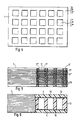
- Fig. 1 in Draufsicht einen Verbundkörper in einer er sten Ausführungsform mit einer geometrischen Anordnung von Perforationen in dem Verbundkörper,
- Fig. 2 im Schnitt den plattenförmigen Verbundkörper nach Fig. 1, bestehend aus perforierten Kunststoffolien und vollflächigen Deckfolien,
- Fig. 3 im Schnitt eine zweite Ausführungsform eines Verbundkörpers, mit einem Plattenkern aus perforierten Kunststoffolien und vollflächigen Folien,
- Fig. 4 in Draufsicht eine dritte Ausführungsform eines ebenen Verbundkörpers, mit rechteckförmigen bzw. quadratischen Perforationen,
- Fig. 5 einen Schnitt durch den Verbundkörper nach Fig. 4, als Lochplatte mit durchgehenden Perforationen,
- Fig. 6 im Schnitt, mit teilweise vergrößertem Ausschnitt, eine vierte Ausführungsform eines Verbundkörpers mit einer einzelnen perforierten Kernplatte und vollflächigen Deckplatten,
- Fig. 7 einen Schnitt, mit teilweise vergrößertem Ausschnitt, durch eine fünfte Ausführungsform des Verbundkörpers, die aus mehreren gekrümmten perforierten Kernplatten und gekrümmten vollflächigen Deckplatten besteht, wobei die geometrische Anordnung der Perforationen von Kernplatte zu Kernplatte variiert,
- Fig. 8 im Schnitt, mit vergrößertem Ausschnitt, eine sechste Ausführungsform eines Verbundkörpers aus perforierten und vollflächigen Platten, bei denen die Größe und geometrische Anordnung der Perforationen von Platte zu Platte sich ändert,
- Fig. 9 im Schnitt, mit vergrößertem Ausschnitt, eine siebente Ausführungsform eines Verbundkörpers, der aus mehreren, perforierten Kernplatten aufgebaut ist, bei denen die geometrische Anordnung der Perforationen von Kernplatte zu Kernplatte sich ändert,
und - Fig. 10 einen Schnitt, mit vergrößertem Ausschnitt, durch eine achte Ausführungsform eines Verbundkörpers, bestehend aus einem aus perforierten Platten zusammengesetzten Kern und vollflächigen Deckplatten, wobei die perforierten Platten unterschiedliche geometrische Anordnung der Perforationen zueinander aufweisen und die Platten mit offenen Perforationen mit solchen abwechseln, deren Perforationen mit Füllmaterialien ausgefüllt sind.
- Fig. 1 in plan view of a composite body in a he most embodiment with a geometrical arrangement of perforations in the composite body,
- 2 in section the plate-shaped composite body according to FIG. 1, consisting of perforated plastic films and full-surface cover films,
- 3 shows in section a second embodiment of a composite body, with a plate core made of perforated plastic films and full-area films,
- 4 is a plan view of a third embodiment of a flat composite body, with rectangular or square perforations,
- 5 shows a section through the composite body according to FIG. 4, as a perforated plate with continuous perforations,
- 6 in section, with a partially enlarged cutout, a fourth embodiment of a composite body with a single perforated core plate and full-surface cover plates,
- Fig. 7 shows a section, with a partially enlarged section, through a fifth embodiment of the Composite body, which consists of several curved perforated core plates and curved full-surface cover plates, the geometric arrangement of the perforations varying from core plate to core plate,
- 8 in section, with an enlarged cutout, a sixth embodiment of a composite body made of perforated and full-surface plates, in which the size and geometric arrangement of the perforations changes from plate to plate,
- 9 in section, with an enlarged detail, a seventh embodiment of a composite body which is constructed from a plurality of perforated core plates, in which the geometrical arrangement of the perforations changes from core plate to core plate,
and - 10 shows a section, with an enlarged cutout, through an eighth embodiment of a composite body, consisting of a core composed of perforated plates and full-area cover plates, the perforated plates having different geometrical arrangements of the perforations with respect to one another and the plates with open perforations alternating with those, the perforations are filled with filling materials.
Die erste Ausführungsform nach den Figuren 1 und 2 stellt eine einfache Ausführungsform eines Verbundkörpers 1 in Getalt einer homogenen, ebenen Platte dar, die aus einer Anzahl dünner, mono- und/oder biaxial verstreckter, koextrudierter Kunststoffolien 5′, 5˝, 5‴ mit äußeren Siegelschichten 10 unter Druck und Temperatur zusammengefügt wurde. Die beiden äußeren, vollflächigen Deckfolien 6 schließen die Kunststoffolien 5′, 5˝, 5‴, welche die Gesamtdicke des Verbundkörpers 1 bilden, ein. Die Kunststoffolien 5′, 5˝, 5‴ haben Perforationen 7′, 7˝, 7‴ in Gestalt beliebig geformter Aussparungen. Im Beispiel nach Fig. 1 sind sie als runde Löcher gezeigt. Durch entsprechendes, sich an der Geometrie der Perforationen 7′, 7˝, 7‴ orientierendes Schichten der einzelnen Kunststoffolien 5′, 5˝, 5‴... werden die Aussparungen gemäß Figur 1 zueinander versetzt, d.h. alternierend gegeneinander auf Lücke angeordnet.The first embodiment according to Figures 1 and 2 represents a simple embodiment of a composite body 1 in the form of a homogeneous, flat plate, which consists of a number of thin, mono- and / or biaxially stretched, coextruded
In der Draufsicht nach Fig. 1 zeigen die Perforationen 7′ an, die mit vollen Linien gezeichnet sind, daß es sich um Ausnehmungen in der obersten Kunststoffolie 5′ handelt. Die Perforationen 7˝ in der darunter liegenden Kunststoffolie 5˝ sind gestrichelt eingezeichnet, während die Perforationen 7‴ in der dritten Kunststoffolie 5‴ von oben (s. Fig. 2) mit den Perforationen 7′ der obersten Kunststoffolie zur Deckung kommen und daher in der Draufsicht nach Fig. 1 nicht erkennbar sind. Jede der Kunststoffolien 5′, 5˝, 5‴ ... trägt zumindest eine Siegelschicht 10, die während des thermischen Verpressens des Verbundkörpers schmilzt, wobei die Schmelze die Perforationen 7′, 7˝, 7‴ ... auffüllt und nach dem Abkühlen einen untrennbaren Verbund zwischen den einzelnen Kunststoffolien herstellt.In the plan view of Fig. 1 show the perforations 7 ', which are drawn with full lines that there are recesses in the top plastic film 5'. The
Eine wechselweise Schichtung von perforierten Kunststoffolien 5′, 5˝, 5‴ ... mit vollflächigen Folien 5 weist die in Fig. 3 gezeigte zweite Ausführungsform des Verbundkörpers 1 auf. Der Stapel aus perforierten und vollflächigen Folien 5′, 5˝ 5‴ und 5 wird von Deckfolien 6 umschlossen, die eine größere Dicke als die Folien des Stapels aufweisen. Die Perforationen 7′ und 7˝ bzw. 7˝ und 7‴ sind deckungsgleich bzw. zueinander versetzt angeordnet.An alternate layering of perforated
Die Deckfolien 6 sind beide reliefartig strukturiert, jedoch liegt es auf der Hand, daß beide auch glatt oder nur die obere oder nur die untere Deckfolie glatt sein können.The
Die dritte Ausführungsform des Verbundkörpers 1 nach den Figuren 4 und 5 unterscheidet sich von den Ausführungsbeispielen nach den Figuren 1 bis 3 dadurch, daß die Schichtung der einzelnen Kunststoffolien 5′, 5˝, 5‴ so erfolgt, daß sich die Perforationen 7′, 7˝, 7‴ decken. Aus dieser geometrischen Anordnung resultiert ein Verbundkörper in Gestalt einer hoch beanspruchbaren Lochplatte mit offenen Querschnitten.The third embodiment of the composite body 1 according to FIGS. 4 and 5 differs from the exemplary embodiments according to FIGS. 1 to 3 in that the stratification of the individual
In der Draufsicht von Fig. 4 sind die rechteckförmigen bzw. quadratischen Perforationen 7′, 7˝, 7‴ ... der Kunststoffolien 5′, 5˝, 5‴ ... erkennbar, die miteinander fluchten und somit offene Querschnitte des Verbundkörpers 1 bilden. Die Schnittdarstellung der Fig. 5 zeigt die einzelnen, übereinandergeschichteten Kunststoffolien 5′, 5˝, 5‴ .... Bei dieser dritten Ausführungsform des Verbundkörpers 1 sind Deckfolien nicht vorhanden. Jede der Kunststoffolien 5′, 5˝, 5‴ ist mit mindestens einer Siegelschicht 10 ausgestattet.4, the rectangular or
Während die in den Figuren 1 bis 5 gezeigten Ausführungsbeispiele des Verbundkörpers aus dünnen, verstreckten Folien, im Dickenbereich von 10 bis 500 µm, hergestellt werden, ist die Fertigung des Verbundkörpers in derselben Weise selbstverständlich auch aus wesentlich dickeren Laminaten möglich. In diesen Fällen sind die dünnen Kunststoffolien 5′, 5˝, 5‴ bzw. 5 durch im Dickenbereich von mehreren Millimetern liegende Laminate 2′, 2˝, 2‴ bzw. 2 ersetzt, die in einer Vorstufe in identischer Weise wie der Verbundkörper aus den Folieneinzellagen thermisch verprebt werden. Dabei ist es für das Endergebnis unerheblich, ob die Perforationen bereits in die für die Laminatherstellung vorgesehenen Einzelfolien oder erst nachträglich in das fertig verpreßte vollflächige Laminat eingestanzt werden. In den Figuren 2 und 3 werden die Laminate durch in Klammer gesetzte Bezugszahlen 2′, 2˝, 2‴ und 2 angedeutet.While the exemplary embodiments of the composite body shown in FIGS. 1 to 5 are produced from thin, stretched foils in the thickness range from 10 to 500 μm, the production of the composite body in the same way is of course also possible from much thicker laminates. In these cases, the thin
Die in Figur 6 gezeigte vierte Ausführungsform der Erfindung besitzt ein erhöhtes axiales Trägheitsmoment des Verbundkörpers 1 gegen Biegebeanspruchung, durch Vergrößerung der Dicke des belastbaren Querschnittes bei gleichzeitiger Minimierung der Gewichtszunahme infolge der vergrößerten Dicke des Verbundkörpers 1. Erreicht wird dies durch Kombination der beiden Deckplatten 4 mit einer hochfesten, Aussparungen 12 aufweisenden und damit im Gewicht deutlich reduzierten Distanzplatte 13, die an der Ober- und Unterseite mit einer Siegelschicht 10 ausgestattet ist. Der Verbundkörper 1 läßt sich in einem Arbeitsgang entweder durch Verpressung entsprechend geschichteter, vollflächiger oder bereits perforierter Folienlagen herstellen, oder durch Kombination der in separaten Einzelschritten aus Einzelfolien gepreßten und perforierten Laminate.The fourth embodiment of the invention shown in FIG. 6 has an increased axial moment of inertia of the composite body 1 against bending stress, by increasing the thickness of the resilient cross-section while minimizing the weight increase due to the increased thickness of the composite body 1. This is achieved by combining the two cover plates 4 with a high-
Gegenüber der vierten Ausführungsform der Figur 6 weist die in Figur 7 dargestellte fünfte Ausführungsform des Verbundkörpers 1 mehrere dünne perforierte Kunststoffplatten 9′, 9˝, 9‴ zwischen den zwei Deckplatten 4 auf. Dieses Konzept ermöglicht die Maßschneiderei von auf den Belastungsfall bzw. das jeweilige Anwendungsgebiet zugeschnittener Verbundkörper. Im einfachsten Fall lassen sich Dicke und Anzahl der Kunststoffplatten sowie deren Anordnung im Schichtenverbund, beispielsweise das Variieren der Plattendicke von innen nach außen, verändern. Desweiteren kann durch die Wahl der Perforationsgeometrie, d.h. der Querschnittsgröße, Form und Lochteilung jeder einzelnen Platte, sowie der geometrischen Anordnung der Perforationen im Gesamtverbund, Einfluß auf die Eigenschaften des fertigen Verbundkörpers genommen werden.Compared to the fourth embodiment of Figure 6, the fifth embodiment of the composite body 1 shown in Figure 7 has a plurality of thin
Eine sechste Ausführungsform des Verbundkörpers 1 gibt Figur 8 wieder. Hierbei sind zwischen perforierten Kunststoffplatten 9′, 9˝ und 9˝, 9‴ zusätzliche vollflächige Kunststoffplatten 9 eingebaut. Diese Sandwich-Bauweise bietet sich zur Kombination von Platten aus unterschiedlichen Werkstoffen an, wobei neben polymeren Werkstoffen in nicht verstärkter Form auch durch Materialien, wie Glas-, Textil-, Metall- oder Karbonfasern, ferner durch Metallbleche oder Metallgewebe oder Textilien aus natürlichen oder synthetischen Fasern verstärkte, polymere Werkstoffe in Betracht kommen. Dabei ist es notwendig, für die Verbindung der unterschiedlichsten Werkstoffe gegebenenfalls geeignete Haftvermittler- oder Kleberschichten einzubauen.FIG. 8 shows a sixth embodiment of the composite body 1. Here are between perforated
Beide Deckplatten 4 sind reliefartig strukturiert, jedoch kann auch nur eine Deckplatte strukturiert sein, während die andere Deckplatte glatt ausgebildet ist.Both cover plates 4 are structured in relief, but only one cover plate can be structured, while the other cover plate is smooth.
Während die in den Figuren 6 bis 8 gezeigten Ausführungsformen des Verbundkörpers durch Verwendung von Deckplatten stets eine geschlossene, ebene oder reliefartig strukturierte Oberfläche aufweisen, unterscheidet sich davon die in Figur 9 dargestellte siebente Ausführungsform durch eine perforierte Oberfläche.While the embodiments of the composite body shown in FIGS. 6 to 8 always have a closed, flat or relief-like structured surface by using cover plates, the seventh embodiment shown in FIG. 9 differs from this in that it has a perforated surface.
Der Verbundkörper 1 ist aus Kunststoffplatten 14′, 14˝, ... 14iv mit Perforationen 15′, 15˝ ... 15iv zusammengesetzt, die unterschiedliche Durchmesser bzw. Abmessungen haben und gegeneinander so versetzt sind, daß die Perforationen der übereinandergeschichteten Kunststoffplatten trotz gegenseitiger Versetzung sich teilweise überlappen, und bei Betrachtung in Richtung der Plattendicke miteinander in Verbindung stehen, d.h. offene Querschnitte bilden. Selbstverständlich sind auch Schichtungen der Kunststoffplatten möglich, bei denen die Versetzung der Perforationen zueinander zu geschlossenen Querschnitten führen. In Figur 9 sind auch die Siegelschichten 10 auf den einzelnen Kunststoffplatten eingezeichnet.The composite body 1 is composed of
Durch geeignete Auswahl und geometrische Anordnung der Perforationen in den den Verbundkörper 1 bildenden Einzelplatten 14′, 14˝, 14‴ ... können somit hochfeste, geschlossene sowie durchlässige, freie Querschnitte unterschiedlicher Größen aufweisende Verbundplatten gefertigt werden.Through suitable selection and geometrical arrangement of the perforations in the
Neben der hervorragenden Biegesteifigkeit der Verbundkörper ergibt deren Sandwich-Bauweise auch erhebliche Verbesserungen des Durchbruchverhaltens bei stoßartiger Belastung, wie sie bei der Anwendung der Verbundkörper als durchbruch- und durchschußhemmende Abschirmmaterialien vor allem verlangt werden. Erfahrungsgemäß weisen homogene Materialien bei Beschädigungen, z.B. in Form von An- oder Einrissen ein meistens unerwünschtes Rißfortpflanzungsverhalten auf, das die Durchbruch- und Durchschußfestigkeit verringert. Eine Maßnahme zur Beeinflussung dieses Phänomens stellt der gezielte Einbau von Störstellen in das Material dar. Beispielsweise kann in einfachster Ausführung der Aufbau des in Figur 7 gezeigten Verbundkörpers für durchschußhemmende Abschirmungen verwendet werden. Bei den durch ihre versetzt ausgerichteten Perforationen als "Labyrinth-Platten" einzustufenden Verbundkörpern wird der Effekt ausgenutzt, daß ein eindringendes Projektil infolge Durchdringens von zonen, wie Hohlraum und Festkörper, mit unterschiedlichen Widerständen gegenüber der Geschoßenergie stets hohe Schädigungsarbeit verrichten muß und somit zwangsläufig schneller in einem solchen Material als in einem homogenen Material abgebremst wird. Die Aufzehrung der Geschoßenergie bewirken die wechselnden Materialzonen in zweifacher Hinsicht, nämlich zum einen dadurch, daß das Projektil zusätzlich aus seiner geradlinigen Bahn abgelenkt wird und zum anderen durch die wechselnden Widerstände der Materialzonen. Die in Figur 10 dargestellten Ausführungsformen des Verbundkörpers 1 bieten durch Kombination homogener, geschlossener Deckplatten 4 mit perforierten, aus unterschiedlichen Polymeren bestehenden Kunststoffplatten 14′, 14˝ mit solchen perforierten Platten 14, deren Perforationen 15 mit unterschiedlichen Materialien 16, 16′, 16˝ ... ausgefüllt sind, umfangreiche Möglichkeiten zur Eigenschaftsmodifikation des Verbundkörpers. Zur Befüllung der Perforationen der Platten 14 können z.B. mit der Perforationsform korrespondierende Stanzlinge aus Polymeren, Metallen, natürlichen oder synthetischen Textilien, Glas, Keramik, Holz, Leder, natürlichen oder synthetischen Kautschuken herangezogen werden. Weiterhin kommen als Füllmaterial Formkörper in Gestalt von Kugeln, wie z.B. aus Metall, oder mineralischen Werkstoffen, wie Glas oder Keramik, Plättchen, wie z.B. aus Glimmer, oder Körnchen, wie z.B. Polymergranulaten, in Betracht. Selbstverständlich lassen sich die Perforationen auch mit Pulvern und Stäuben jeglicher Art befüllen. Sofern auf Flüssigkeiten zurückgegriffen wird, deren Verdampfungstemperatur über der der Preßtemperatur liegt, sind auch diese Materialien einsetzbar. Dasselbe gilt auch für reaktive Medien, wie z.B. schäumbare Produkte, deren Reaktionsmechanismus entweder schon beim Fertigen des Formkörpers oder erst bei einer spezifischen Beanspruchung, z.B. Temperaturbelastung im Brandfall, oder Luftkontakt bei mechanischer Beschädigung, des Verbundkörpers ausgelöst wird. Der Einbau reaktiver Komponenten ergibt Platten mit einem sogenannten "Selbstheilungseffekt", d.h. an Schadstellen des Verbundkörpers bewirken Reaktionen freigesetzter Produkte den Verschluß des lokalen Defektes.In addition to the excellent bending stiffness of the composite body, their sandwich construction also results in significant improvements in the breakthrough behavior under impact loads, as are required above all when using the composite body as a breakthrough and bullet-resistant shielding material. Experience has shown that homogeneous materials, in the event of damage, for example in the form of tears or tears, usually have an undesirable crack propagation behavior which reduces the resistance to breakdown and bullet penetration. One measure for influencing this phenomenon is the targeted incorporation of impurities in the material. For example, the structure of the structure shown in FIG 7 composite body shown for bullet-resistant shields can be used. In the case of the composite bodies, which are classified as "labyrinth plates" due to their staggered perforations, the effect is exploited that an penetrating projectile due to penetration of zones, such as cavities and solid bodies, with different resistances to the projectile energy must always do a great deal of damage work and thus inevitably faster such a material is braked as in a homogeneous material. The consumption of the projectile energy causes the changing material zones in two ways, firstly by the fact that the projectile is additionally deflected from its straight path and secondly by the changing resistances of the material zones. The embodiments of the composite body 1 shown in FIG. 10 offer a combination of homogeneous, closed cover plates 4 with perforated plastic plates 14 ', 14' consisting of different polymers with such
Geeignet zur Herstellung der vielschichtigen Verbundkörper sind thermoplastische Kunststoffolien mit mindestens einer Heißsiegelschicht. Besonders geeignet sind Folien aus thermoplastischen Kunststoffen aus der Gruppe der Polyester und der Polyolefine.Thermoplastic plastic films with at least one heat seal layer are suitable for producing the multilayer composite bodies. Films made of thermoplastics from the group of polyesters and polyolefins are particularly suitable.
Unter Polyester sind Polyester-Homo- und -Copolymere, Gemische verschiedener Polyester sowie Abmischungen von Polyestern mit anderen Polymeren zu verstehen.Polyester is to be understood as meaning polyester homopolymers and copolymers, mixtures of different polyesters and mixtures of polyesters with other polymers.
Als Polyester werden insbesondere Propylen-Homopolymere oder -Copolymere eingesetzt, wobei letztere zum überwiegenden Teil aus Propyleneinheiten zusammengesetzt sind.In particular, propylene homopolymers or copolymers are used as polyesters, the latter being predominantly composed of propylene units.
Als Heißsiegelschichten können die üblicherweise zu diesem Zweck bei der Folienherstellung eingesetzten Beschichtungen verwendet werden. Dies sind bevorzugt statistische Copolymere aus Ethylen-Propylen-Bausteinen sowie Copolyester, enthaltend Ethylenterephthalat- und Isophthalat-Einheiten. Desweiteren kommen als Siegel- oder Haftvermittlerschichten Ethylenvinylacetatcopolymere, Polyurethane, Polyvinylbutyral, Acrylat-Copolymere und Copolyamide in Betracht.The coatings which are usually used for this purpose in film production can be used as heat-sealing layers. These are preferably statistical copolymers of ethylene-propylene units and copolyesters containing ethylene terephthalate and isophthalate units. Furthermore, ethylene-vinyl acetate copolymers, polyurethanes, polyvinyl butyral, acrylate copolymers and copolyamides are suitable as sealing or adhesion promoter layers.
Was die einzelnen Folienlagen des den Verbundkörper bildenden Preßlaminates betrifft, handelt es sich um Folien der vorbeschriebenen Art, die eine Dicke im Bereich von 10 bis 300 µm, insbesondere von 40 bis 200 µm, aufweisen. Die Dicke der Heißsiegelschicht, die ein- oder beidseitig auf der Kunststoffolie bzw. der Kunststoffplatte aufgebracht ist, überschreitet üblicherweise 10 % der Dicke der Trägerfolie nicht und liegt im Bereich von 0,5 bis 5 µm.As far as the individual film layers of the press laminate forming the composite body are concerned, films of the type described above have a thickness in the range from 10 to 300 μm, in particular from 40 to 200 μm. The thickness of the heat seal layer, which is applied to the plastic film or the plastic plate on one or both sides, usually does not exceed 10% of the thickness of the carrier film and is in the range from 0.5 to 5 μm.
Als Ausgangsmaterial zur Fertigung des verbundkörpers sind neben den beschriebenen Laminaten, gepreßt aus einer Anzahl der Kunststoffolien in einem separaten Schritt, auch aus den Laminaten in einem weiteren Schritt bereits gepreßte, mehrere Millimeter dicke, steife Kunststoffplatten geeignet. Die Perforationen können entweder in den Ausgangsfolien eingebracht sein oder im Nachhinein an den Laminaten bzw. Kunststoffplatten durch Stanzen vorgenommen werden.In addition to the laminates described, pressed from a number of plastic films in a separate step, several mm thick, stiff plastic plates that are already pressed from the laminates are suitable as the starting material for producing the composite body. The perforations can either be made in the starting foils or can be made afterwards on the laminates or plastic plates by punching.
Hinsichtlich der Ausgestaltung der Perforationen sowie deren geometrischen Anordnung im Verbundkörper ist nach Berücksichtigung der für die Anwendung der Platte wesentlichen Festigkeitskriterien eine Vielzahl von Variationen möglich. Es kann dabei auf eine Vielfalt von funktionellen sowie dekorativen Lochmustern zurückgegriffen werden, wie sie von der einschlägigen Industrie seit langem zur Produktion von Loch- oder Zierblechen eingesetzt werden. Die Kombination von farbigen Platten mit Zierlochungen liefert dekorative Vebundkörper für entsprechende Anwendungen.With regard to the design of the perforations as well their geometrical arrangement in the composite body, after taking into account the strength criteria essential for the use of the plate, a large number of variations is possible. A variety of functional and decorative hole patterns can be used, as have long been used by the relevant industry to produce perforated or decorative plates. The combination of colored panels with decorative perforations provides decorative composite bodies for corresponding applications.
Für verschiedene Verbundkörper ergeben sich unterschiedliche Anwendungsmöglichkeiten. Besondere Einsatzmöglichkeiten sind im Fahrzeug- (Auto, Flugzeug, Eisenbahn) und im Apparatebau vorhanden, da auf beiden GebietenDifferent application possibilities arise for different composite bodies. Special applications are available in vehicle (car, plane, railroad) and apparatus construction, as in both areas
Konstruktionselemente mit hoher mechanischer Festigkeit und möglichst niedrigem Gewicht angestrebt werden.Construction elements with high mechanical strength and the lowest possible weight are aimed for.
Der labyrinthartige Aufbau des Verbundkörpers macht ihn für einen Einsatz als durchbruch- und durchschußhemmendes Abschirmmaterial insbesondere geeignet.The labyrinthine structure of the composite body makes it particularly suitable for use as a breakthrough and bullet-resistant shielding material.
Die Ausbildung beliebiger Perforationsgeometrien und deren Anordnung im Verbund sowie die Kombination farblich unterschiedlicher Schichten eröffnen dem Verbundkörper die Anwendung für Dekorationszwecke im Messebau, Bauwesen, Innenausbau, Fassadenbau und sonstiger architektonischer Gestaltung in und an Gebäuden.The formation of any perforation geometries and their arrangement in the composite as well as the combination of different layers of color open the composite body to use for decorative purposes in trade fair construction, construction, interior design, facade construction and other architectural design in and on buildings.
Die mit offenen Perforationsquerschnitten ausgerüsteten Verbundkörper sind für Drainagesysteme im Straßen-, Tunnel- und Tiefbau einsetzbar. Die Verwendung als Sicht- und Lärmschutzblende mit reduzierten Windbelastungen ist ferner möglich.Those equipped with open perforation cross sections Composite bodies can be used for drainage systems in road, tunnel and civil engineering. It can also be used as a screen and noise shield with reduced wind loads.
Claims (29)
Applications Claiming Priority (2)
| Application Number | Priority Date | Filing Date | Title |
|---|---|---|---|
| DE3931451A DE3931451A1 (en) | 1989-09-21 | 1989-09-21 | DIMENSIONALLY STABLE COMPOSITE BODY, METHOD FOR THE PRODUCTION THEREOF AND ITS USE |
| DE3931451 | 1989-09-21 |
Publications (2)
| Publication Number | Publication Date |
|---|---|
| EP0418773A2 true EP0418773A2 (en) | 1991-03-27 |
| EP0418773A3 EP0418773A3 (en) | 1991-11-13 |
Family
ID=6389848
Family Applications (1)
| Application Number | Title | Priority Date | Filing Date |
|---|---|---|---|
| EP19900117828 Withdrawn EP0418773A3 (en) | 1989-09-21 | 1990-09-17 | Dimensionally stable laminate, its use, and method of manufacture |
Country Status (3)
| Country | Link |
|---|---|
| EP (1) | EP0418773A3 (en) |
| JP (1) | JPH03138135A (en) |
| DE (1) | DE3931451A1 (en) |
Cited By (5)
| Publication number | Priority date | Publication date | Assignee | Title |
|---|---|---|---|---|
| US5356705A (en) * | 1992-01-09 | 1994-10-18 | The Dow Chemical Company | Laminated, weatherable film-capped siding structure |
| WO2002011978A1 (en) * | 2000-08-08 | 2002-02-14 | 3M Innovative Properties Company | Cloth-like polymeric films |
| WO2003059750A3 (en) * | 2002-01-16 | 2004-03-04 | Mega Plast S A | Perforierte stretchfolie |
| US7138169B2 (en) | 2003-03-05 | 2006-11-21 | 3M Innovative Properties Company | Cloth-like polymeric film with directional tear |
| EP3484603A4 (en) * | 2016-07-18 | 2020-03-18 | Entegris, Inc. | Spacer film with integrated lamination strip |
Families Citing this family (3)
| Publication number | Priority date | Publication date | Assignee | Title |
|---|---|---|---|---|
| JPH10291250A (en) * | 1997-02-24 | 1998-11-04 | Sekisui Chem Co Ltd | Polyolefin molded body and its manufacture |
| DE19853265C1 (en) * | 1998-11-18 | 2000-07-20 | Hightech Produktions Ges M B H | Sliding board |
| DE102018105246B4 (en) | 2017-04-25 | 2024-02-15 | Deutsches Zentrum für Luft- und Raumfahrt e.V. | Method for producing a reinforced fiber composite material, fiber composite material and aircraft or spacecraft |
Citations (4)
| Publication number | Priority date | Publication date | Assignee | Title |
|---|---|---|---|---|
| DE1704996A1 (en) * | 1967-07-18 | 1971-07-22 | Gustav Sachsenroeder Sen | Process for the production of laminates |
| US3919382A (en) * | 1971-12-29 | 1975-11-11 | Union Carbide Corp | Expanding process with non-aligned molds |
| EP0207047A1 (en) * | 1985-01-25 | 1986-12-30 | Harald Dipl.-Ing. Schobermayr | Stiff moulding consisting of pressed oriented plastic layers as well as method of producing same |
| EP0259128A2 (en) * | 1986-09-01 | 1988-03-09 | Nitto Denko Corporation | Composite porous sheet of thermoplastics layers on support |
Family Cites Families (3)
| Publication number | Priority date | Publication date | Assignee | Title |
|---|---|---|---|---|
| US4274901A (en) * | 1978-03-24 | 1981-06-23 | The United States Of America As Represented By The Administrator Of The National Aeronautics And Space Administration | Method of making a partial interlaminar separation composite system |
| DE3708780A1 (en) * | 1987-03-18 | 1988-09-29 | Helio Folien Gmbh | MULTILAYER FILM |
| US4935271A (en) * | 1988-09-06 | 1990-06-19 | W. R. Grace & Co.-Conn. | Lettuce packaging film |
-
1989
- 1989-09-21 DE DE3931451A patent/DE3931451A1/en not_active Withdrawn
-
1990
- 1990-09-17 EP EP19900117828 patent/EP0418773A3/en not_active Withdrawn
- 1990-09-20 JP JP2251679A patent/JPH03138135A/en active Pending
Patent Citations (4)
| Publication number | Priority date | Publication date | Assignee | Title |
|---|---|---|---|---|
| DE1704996A1 (en) * | 1967-07-18 | 1971-07-22 | Gustav Sachsenroeder Sen | Process for the production of laminates |
| US3919382A (en) * | 1971-12-29 | 1975-11-11 | Union Carbide Corp | Expanding process with non-aligned molds |
| EP0207047A1 (en) * | 1985-01-25 | 1986-12-30 | Harald Dipl.-Ing. Schobermayr | Stiff moulding consisting of pressed oriented plastic layers as well as method of producing same |
| EP0259128A2 (en) * | 1986-09-01 | 1988-03-09 | Nitto Denko Corporation | Composite porous sheet of thermoplastics layers on support |
Cited By (9)
| Publication number | Priority date | Publication date | Assignee | Title |
|---|---|---|---|---|
| US5356705A (en) * | 1992-01-09 | 1994-10-18 | The Dow Chemical Company | Laminated, weatherable film-capped siding structure |
| WO2002011978A1 (en) * | 2000-08-08 | 2002-02-14 | 3M Innovative Properties Company | Cloth-like polymeric films |
| US6635334B1 (en) | 2000-08-08 | 2003-10-21 | 3M Innovative Properties Company | Cloth-like polymeric films |
| KR100736190B1 (en) * | 2000-08-08 | 2007-07-06 | 쓰리엠 이노베이티브 프로퍼티즈 캄파니 | Cloth-like polymeric films |
| WO2003059750A3 (en) * | 2002-01-16 | 2004-03-04 | Mega Plast S A | Perforierte stretchfolie |
| US7682683B2 (en) | 2002-01-16 | 2010-03-23 | Mega Plast S.A. | Stretch film |
| US7138169B2 (en) | 2003-03-05 | 2006-11-21 | 3M Innovative Properties Company | Cloth-like polymeric film with directional tear |
| CN100415842C (en) * | 2003-03-05 | 2008-09-03 | 3M创新有限公司 | Cloth-like polymeric film with directional tear |
| EP3484603A4 (en) * | 2016-07-18 | 2020-03-18 | Entegris, Inc. | Spacer film with integrated lamination strip |
Also Published As
| Publication number | Publication date |
|---|---|
| JPH03138135A (en) | 1991-06-12 |
| DE3931451A1 (en) | 1991-04-11 |
| EP0418773A3 (en) | 1991-11-13 |
Similar Documents
| Publication | Publication Date | Title |
|---|---|---|
| DE69532193T2 (en) | HEAT-CONDUCTIVE NON-METAL HONEYCOMB STRUCTURES AND METHOD | |
| EP2715835B1 (en) | Energy storage module comprising a plurality of, in particular, prismatic storage cells, and method for producing an energy storage module, and also method for producing an end plate for an energy storage module | |
| DE60018969T2 (en) | SUPPORT STRUCTURE FOR COMPOSITE COMPONENTS | |
| EP0557597B1 (en) | Thermal and acoustic insulating laminate | |
| DE3620388A1 (en) | DRAIN MAT WITH HIGH PRESSURE RESISTANCE | |
| DE102013206086A1 (en) | Multilayer structural component | |
| DE19939227B4 (en) | Composite material | |
| WO2007088048A1 (en) | Sound-absorbing insulation part having hardening embossings | |
| EP0229977A2 (en) | Sound-reducing cladding for the engine compartment of a motor vehicle | |
| DE3934555A1 (en) | Rigid for laminate for coachwork parts - has laminar construction reinforced with core of polymer fibres and multilayer skins of carbon fibre, all impregnated with epoxy] resin | |
| DE102006056612B4 (en) | Method for producing a composite sandwiched material and composite material | |
| EP0418773A2 (en) | Dimensionally stable laminate, its use, and method of manufacture | |
| EP0418772A2 (en) | Dimensionally stable laminate, and method of manufacture | |
| DE102008062678B4 (en) | Composite component with a honeycomb structure | |
| EP1698452A1 (en) | Composite panel | |
| DE10317670A1 (en) | A hollow chamber element for motor cars with a reinforcing core layer, chambers and a crosslinked synthetic plastic foam sheath useful in motor car construction | |
| DE3220768C2 (en) | Process for the production of molded parts from fiber nonwovens provided with a structured decorative layer | |
| WO2001055524A1 (en) | Structural component and a method for producing same | |
| EP0248199B2 (en) | Multilayer lining element | |
| EP3877171B1 (en) | Method for producing a thermoplastically deformable fibre-reinforced flat semi-finished product | |
| DE10060816A1 (en) | Multi-layer molded body with locally limited reinforcement elements | |
| EP0445638A2 (en) | High-stregth laminate of compressed, orientated thermoplastic sheets and method of making it | |
| DE3013134C2 (en) | Process for the production of molded parts by deep drawing and / or pressing | |
| DE3839218A1 (en) | DIMENSIONALLY STABLE COMPOSITE BODY | |
| DE102020003819B4 (en) | Underbody paneling part for a vehicle and method for its manufacture |
Legal Events
| Date | Code | Title | Description |
|---|---|---|---|
| PUAI | Public reference made under article 153(3) epc to a published international application that has entered the european phase |
Free format text: ORIGINAL CODE: 0009012 |
|
| AK | Designated contracting states |
Kind code of ref document: A2 Designated state(s): AT BE CH DE FR GB IT LI LU NL SE |
|
| PUAL | Search report despatched |
Free format text: ORIGINAL CODE: 0009013 |
|
| AK | Designated contracting states |
Kind code of ref document: A3 Designated state(s): AT BE CH DE FR GB IT LI LU NL SE |
|
| 17P | Request for examination filed |
Effective date: 19920327 |
|
| STAA | Information on the status of an ep patent application or granted ep patent |
Free format text: STATUS: THE APPLICATION HAS BEEN WITHDRAWN |
|
| 18W | Application withdrawn |
Withdrawal date: 19930212 |