EP0419320A1 - Automatic harmonizing device for an opto-electronic system - Google Patents
Automatic harmonizing device for an opto-electronic system Download PDFInfo
- Publication number
- EP0419320A1 EP0419320A1 EP90402493A EP90402493A EP0419320A1 EP 0419320 A1 EP0419320 A1 EP 0419320A1 EP 90402493 A EP90402493 A EP 90402493A EP 90402493 A EP90402493 A EP 90402493A EP 0419320 A1 EP0419320 A1 EP 0419320A1
- Authority
- EP
- European Patent Office
- Prior art keywords
- laser
- image
- sensor
- reticle
- source
- Prior art date
- Legal status (The legal status is an assumption and is not a legal conclusion. Google has not performed a legal analysis and makes no representation as to the accuracy of the status listed.)
- Granted
Links
Images


Classifications
-
- F—MECHANICAL ENGINEERING; LIGHTING; HEATING; WEAPONS; BLASTING
- F41—WEAPONS
- F41G—WEAPON SIGHTS; AIMING
- F41G3/00—Aiming or laying means
- F41G3/32—Devices for testing or checking
- F41G3/326—Devices for testing or checking for checking the angle between the axis of the gun sighting device and an auxiliary measuring device
Definitions
- the invention relates to an automatic harmonization device for an optronic system comprising a laser and two image sensors operating respectively in two different domains of spectral sensitivity.
- the system includes: a laser rangefinder; a distance meter; and a tracking and identification device.
- These devices comprise a common optical channel constituted in particular by means for orienting a common line of sight.
- Harmonization consists in superimposing the optical axes of these three devices so that they have a common line of sight.
- a harmonization carried out on a test bench, in the factory is not preserved after a certain time of operational use of the system. Harmonization must be able to be redone during operational use, as a particular phase of operation, and must be automatic.
- the invention relates more particularly to optronic systems in which the distance meter and the tracking and identification device respectively comprise two image sensors, operating respectively in two different spectral sensitivity domains, having no common wavelength .
- the distance meter comprises an image sensor operating in the band of three to five microns, or in the band of eight to twelve microns, to locate a target in elevation and in bearing
- the identification device and tracking includes an image sensor operating in the 0.7 to 0.9 micron band, that is to say the band of visible and near IR radiation.
- the laser rangefinder transmits at a wavelength not belonging to none of these spectral sensitivity ranges, for example 1.54 microns.
- US Patent 4,155,096 describes an automatic harmonization device for an optronic target designation system, comprising an image sensor and a laser.
- the laser has a wavelength of 1.06 micron, which belongs to the spectral sensitivity range of the image sensor, which extends from 0.4 to 1.1 micron.
- This harmonization device comprises a cube corner towards which the line of sight is oriented, during harmonization. This also consists of switching on the laser.
- the cube corner reflects, towards the image sensor, a fraction of the laser beam.
- the laser beam therefore forms a light spot on the image sensor.
- Image processing makes it possible to determine the difference between this task and the center of the image sensor, and to deduce therefrom a harmonization correction.
- This known device cannot be used when the laser does not have a wavelength within the spectral sensitivity range of the image sensor.
- US Patent 4,422,758 describes a harmonization device for an optronic target designation system, this system comprising: a laser operating at 1.06 micron, an image sensor in the visible radiation domain, and a sensor for images in the field of infrared radiation.
- the harmonization device includes a collimator to which the line of sight is directed, during harmonization.
- a refractory target is placed in the focal plane of the collimator.
- the laser is on and its radiation is focused on the target to create a hot spot emitting visible and infrared radiation.
- the image of this hot spot is detectable simultaneously by the two image sensors and makes it possible to measure the harmonization errors of the axis of the laser with respect to the axes of the two image sensors.
- the drawback of this device is that it requires focusing a large amount of energy on the refractory target. Obtaining a very hot spot is not easy to achieve when the laser has only one medium or low power. On the other hand, the use of the laser leads to a certain energy consumption and a certain reduction in the lifetime of the laser.
- the object of the invention is to propose a harmonization device independent of the power and the wavelength of the laser.
- the object of the invention is a device making it possible to achieve harmonization in two stages.
- a first step is performed using a source associated with the laser, so as to have the same optical axis, and emitting in the spectral sensitivity range of a first sensor.
- a second step is carried out by means of a broadband collimator comprising, in its focal plane, a reticle emitting radiation in the ranges of sensitivity of the two sensors, and which is visible simultaneously by these two sensors.
- an automatic harmonization device for an optronic system comprising a single pupil for a laser, a first and a second image sensor, operating respectively in two different domains of spectral sensitivity; is characterized in that it comprises: a source of collimated radiation, associated with the laser, emitting in the optical axis of the laser, with a wavelength belonging to the spectral sensitivity range of the first sensor; - optical means reflecting the radiation from the source associated with the laser, to form a light spot on the first sensor; - a broadband collimator, comprising, in its focal plane, a screen cut out of holes constituting a reticle illuminated by a source emitting in the two spectral sensitivity domains; this collimator being placed so as to be visible simultaneously by the first and the second image sensor, to form thereon respectively two images of the reticle; means for measuring, on the first sensor, the difference between the positions of the image of the reticle and of the task formed by the source, and deduce therefrom a first harmon
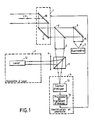
- FIG. 1 represents an example of a conventional optronic system, without a harmonization device, in order to illustrate the operation of the system during its operation outside the harmonization period.
- This system includes: - a rangefinder 2 essentially comprising a laser 12 emitting at the wavelength of 1.54 microns; - a distance meter 3 comprising in particular a sensitive image sensor in the infrared range, from 0.7 to 0.9 micron; a device 4 for target identification and tracking, essentially comprising an image sensor, 13, and an image processing processor, 14.
- the rangefinder 2, the distance meter 3, and the device 4 have a common line of ylsée LV which is orientable by means of a common pointing head, 1, comprising movable mirrors, 10 and 11, driven by servo-mechanisms not shown which are controlled by signals supplied by the image processing processor 14 in order to track a target.
- the rays received by the system are separated by a dichroic blade 8 which lets the infrared radiation intended for the distance meter 3 pass and which reflects the visible radiation intended for the device 4.
- the infrared radiation is then deflected by a mirror 9, then is focused by a converging lens 15 on the sensor of the deviation meter 3.
- the visible radiation is then focused by a converging lens 7 on the image sensor 13.
- a dichroic cube 5 is interposed between the lens 7 and the image sensor 13, to allow the optical axis of the laser beam of the rangefinder 2 to be superimposed on the optical axis of the visible radiation beam focused by the lens 7.
- the beam from the rangefinder 2 is supplied by a laser 12. It passes through a divergent lens 6, then is reflected by the dichroic surface of the dichroic cube 5, then it passes through the convergent lens 7, then is reflected by the dichroic blade 8, and finally it crosses the pointing head 1.
- the diverging lens 6 and the converging lens 7 constitute an afocal system which enlarges the laser beam by reducing its divergence.
- FIG. 2 schematically represents part of a first embodiment of the harmonization device according to the invention.
- This part is a broadband collimator 20, which comprises: a catoptic system of the Casse type grain consisting of two spherical mirrors 24 and 25; a screen 22 cut out of holes 23 constituting a reticle which is lit by a lamp 21 placed behind the screen 22. The center of the reticle is aligned with the optical axis of the mirrors 24 and 25.
- the holes 23 are 4 in number and each have an elongated shape. They form a cross but have no point of intersection.
- the surface 26 of the screen 22, on the side of the catoptric system, is covered with a retroreflective material, such as the paint sold under the brand SCOTCHLITE by the company 3M.
- This paint consists of micro glass beads fixed in a transparent binder. Each micro-ball behaves like a cube corner, returning each ray of light in the direction from which it comes.
- the lamp 21 is an incandescent lamp of the quartz-iodine type, for example, fitted with a filter. This lamp emits both in the field of visible radiation and in the field of infrared radiation.
- the filter makes it possible to balance the light intensity emitted in the visible range with the light intensity emitted in the spectral sensitivity range of the sensor of the deviation meter 3.
- This collimator 20 is integral with the optronic system. It is located outside the useful angular range of the system but it is located in the range accessible by the LV line of sight.
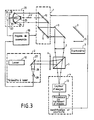
- FIG 3 shows the same system as Figure 1 and a first embodiment of the device according to the invention.
- This figure illustrates a first stage of harmonization consisting in harmonizing the optical axis of the laser 12 with the optical axis of the identification and tracking device 4.
- This first embodiment of the device according to the invention comprises, in addition to the collimator 20: control means 30; and a source of collimated radiation which is associated with the laser 12 so as to have an optical axis coincident with that of the laser 12.
- This source consists of a light-emitting diode 29, a converging lens 28, and a dichroic plate 27. The light beam emitted by the diode 29 visited.
- the control means 30 have outputs connected respectively to inputs of the pointing head 1, of the lamp 21, and the diode 29.
- the control means 30 do not light the lamp 21 but light the diode 29 so that it emits radiation replacing the beam of the laser 12 by having a wavelength which belongs to the field of sensitivity of the image sensor 13.
- the rays emitted by the diode 29 are reflected by the dichroic surface of the cube 5, then are transmitted by the lens 7, then are reflected by the dichroic surface 8, then are transmitted by the head 1 towards the collimator 20.
- the control means 30 orient the line of sight LV of the head 1 in the direction of the collimator 20 throughout the duration of the harmonization.
- the means 30 do not light the lamp 21, the reticle formed by the holes 23 therefore emits no ray.
- the rays emitted by the diode 29 are focused by the retro-reflecting system 24, 25 and form a light spot on the surface 26 of the screen 22.
- the paint covering the surface 26 reflects these rays in the direction from which they originate. They follow the same path in reverse to the dichroic cube 5. About where 50% of the energy of these rays is reflected towards the rangefinder 2 and about 50% of the energy of these rays is transmitted towards the sensor 13.
- the dichroic plate 8 fully reflects the rays emitted by the diode 29 and the rays returned by the collimator 20 because its transition wavelength is located at wavelengths greater than that of the emission of diode 29.
- the lens 7 forms on the image sensor 13 an image of the light spot formed on the screen 22.
- the processor 14 determines and stores the position of this image. This position constitutes a reference for the second stage of harmonization.
- FIG. 4 schematically represents the same optronic system and the same exemplary embodiment of the device according to the invention, illustrating the second step of harmonization.
- the control means 30 no longer light the light-emitting diode 29 but light the lamp 21 of the collimator 20.
- the line of sight LV of the head 1 remains pointed towards the collimator 20.
- the holes 23 cut in the screen 22 constitute a luminous crosshair reticle which is visible simultaneously in the visible radiation field and in the infrared radiation field thanks to the broad emission spectrum of the incandescent lamp 21.
- the rays emitted by the reticle are transmitted by the system catadioptric, 24, 25, then by the head 1, then are separated into two beams by the dichroic blade 8.
- the blade 8 transmits the infrared rays towards the deflection mirror 9, while it reflects the visible rays, towards the lens 7.
- the lens 15 therefore forms an image of the reticle on the sensor of the deviation meter 3 and the lens 7 forms an image of the reticle on the image sensor 13.
- the dichroic blade of cube 5 allows the visible rays from lens 7 to pass entirely.
- the distance meter 3 determines the position of the image of the reticle on its sensor, relative to a reference point of this sensor.
- the image processing processor 14 determines the position of the image of the reticle on the sensor 13, and stores it. It determines two coordinates translating the difference between the position of the image of the reticle and the position, determined previously, of the image of the light spot formed by the diode 29 on the screen 22. The differences thus determined by the variometer 3 and by processor 14 make it possible to deduce therefrom a first and a second corresponding harmonization correction Dant respectively to the harmonization error of the deviation meter with respect to the laser and to the harmonization error of the device 4 with respect to the laser.
- a first possibility of carrying out these corrections consists in memorizing the deviations and in subtracting them from the measurements carried out subsequently by the devometer, on the one hand, and by the processor 14, on the other hand.
- a second possibility of correction consists in canceling the difference observed by the device 4, by modifying the orientation of the optical axis of the laser by means of a deflection mirror mounted on three piezoelectric wedges. The production of such a deflection mirror and of the circuits for controlling the piezoelectric shims is conventional. In this case, it remains to correct the difference observed by the distance meter 3, by subtracting this difference from the measurements made subsequently by the distance meter 3.
- FIG. 5 represents the screen 22 seen from the front, when the light emitted by the light-emitting diode 29 forms a light spot 27 on this screen.
- the light spot 27 has a circular shape, and a surface much greater than that of the holes 23 constituting the reticle.
- FIG. 6 represents an alternative embodiment 22 ′ of the screen 22, comprising holes 23 ′ which constitute a reticle having the shape of a square whose sides are interrupted, to allow this reticle to be produced by photoengraving on a plate metallic, for example.
- the rays emitted by the diode 29 form a light spot 27 ′.
- the width of the holes 23 ′ of the reticle must be small compared to the diameter of the light spot 27 or 27 ′, so that the portion of non-reflecting surface, located inside the light spot, is small compared to the surface of this light spot.
- the harmonization carried out by means of the device according to the invention can be done in two stages, as it was described above, but it can also be done by simultaneously lighting the diode 29 and the lamp 21 of the collimator 20. But then the image processing performed by the processor 14 is more complex since it must distinguish on the sensor 13 the image of the light spot 27 and the image of the reticle formed by the holes 23 which are illuminated by the lamp 21 However, this discrimination is achievable by a conventional method of pattern recognition by correlation, the shape of the task 27 and the shape of the holes 23 being known a priori.
- the light intensity of the image of the task 27 and the light intensity of the image of the reticle, on the sensor 13, can be adjusted independently by acting on the intensity of the supply current of the lamp 21 and on the supply intensity of the diode 29.
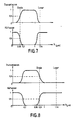
- Figures 7 and 8 show diagrams illustrating the operation of the dichroic cube 5 respectively in two variants of this first embodiment, where the light emitting diode 29 emits at the wavelength of 0.65 microns or else emits at the length d wave of 0.9 micron. In both cases its emission wavelength is close to one of the ends of the spectral sensitivity range of the image sensor 13.
- the dichroic cube 5 must satisfy three requirements simultaneously: - have a reflection coefficient close to 1 for the wavelength of the laser: 1.54 micron; - have a transmission coefficient close to 1 for the entire spectral sensitivity range of sensor 13: 0.7 to 1 micron in this example; - have a reflection coefficient and a transmission coefficient close to 0.5 for the wavelength of the light-emitting diode 29.
- Such a dichroic cube can be produced by conventional methods consisting of deposits of multiple dichroic layers.
- FIG. 7 represents the graph of the transmission coefficient and the graph of the reflection coefficient of the cube 5, as a function of the wavelength, for the variant embodiment comprising a diode 29 emitting at the wavelength of 0.65 micron.
- the two graphs are complementary because practically all the energy which is not transmitted is reflected.
- the transmission coefficient graph includes a plateau of value 1 between 0.7 and 1 micron, with a transition at 0.65 micron, passing to the value 0.5 for the wavelength of the diode, and a transition at above 1 micron which corresponds to the sensitivity limit of the sensor 13, while being less than the wavelength of the laser: 1.54 micron.
- FIG. 8 represents the graph of the transmission coefficient and the graph of the reflection coefficient of the cube 5 for the alternative embodiment comprising a diode 29 emitting at 0.9 micron, the laser still having the same wavelength: 1.54 micron.
- the transmission coefficient graph includes a plateau of value 1 between 0.7 micron and 0.85 micron approximately, with a transition at a wavelength slightly less than 0.7 micron, which is the first border of the sensitivity domain of the sensor 13, and a transition passing through the value 0.5 for the wavelength 0.9 micron which is the emission wavelength of the diode, and which is very close to the second boundary of the domain of sensor sensitivity 13, 1 micron; while being less than the laser wavelength: 1.54 micron.
- the optical means reflecting the radiation from the source associated with the laser may be different from the microbeads covering the surface of the screen 22 of the collimator 20.
- these means consist of a metallic coating constituting a plane mirror in the focal plane of the collimator. The collimator then behaves like a converging lens provided with a plane mirror in its focal plane, it returns a light ray parallel to itself.
- these means consist of a cube corner placed next to the collimator 20, in the angular range accessible to the line of sight LV. It is then necessary for the control means 30 to move the line of sight successively in the direction of the cube corner and in the direction of the collimator 20 in order to carry out the first and second stages of harmonization respectively.
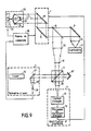
- FIG. 9 represents a second embodiment of the device according to the invention, in which the retroreflective optical means consist of a cube corner 26 ⁇ placed in the extension of the collimated beam emitted by the diode 29, the lens 28, and the semi-transparent plate 27, beyond the dichroic cube 5.
- the dichroic cube 5 is the same as in the first embodiment described above. It reflects 50% of the energy of the radiation from the diode in the direction of the dichroic plate 8, without any utility, and it transmits 50% towards the cube corner 26 ⁇ .
- the rays reflected by the cube corner 26 ⁇ are parallel to the rays arriving on it and they therefore return to the dichroic surface of the cube 5.
- the latter reflects 50% of their energy towards the image sensor 13 where they are focused by a converging lens 33, and it transmits 50% of the energy towards the diode 29, without any utility.
- lenses 6 and 7, which formed an afocal system are eliminated.
- an afocal system consisting of a diverging lens 31 and a converging lens 32, having the function of enlarging the laser beam by reducing its divergence.
- the converging lens 33 is added between the cube 5 and the image sensor 13 in order to focus on the latter the parallel light rays coming either from the afocal system 31, 32, or coming from the diode 29 and collimated by the lens 28.
- the rays coming from the reticle of the collimator 20 are represented at the same time as the rays coming from the diode 29, which corresponds to the case where the two stages of harmonization are carried out simultaneously.
- the rays coming from the reticle are represented with a simple arrow.
- the rays coming from the diode 29 are represented with a double arrow.
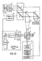
- FIG. 10 schematically represents a third embodiment example adapted to an optronic system similar to those described above but in which the laser is a Raman laser.
- This Raman effect laser comprises an excitation laser 40, of the YAG type, emitting at a wavelength of 1.06 microns, and a Raman effect cell 42 which converts the energy of the excitation laser into radiation. 1.54 micron wavelength laser.
- a deflection mirror 41 is interposed between the laser 40 and the cell 42.
- a filtering device is interposed between the cell 42 and the output of the range finder 2.
- This filtering device consists of an absorber 44 and a dichroic blade 43, inclined at 45 ° with respect to the optical axis of the laser beam leaving the cell 42, to deflect radiation of wavelength 1.06 micron towards the absorber 44. In a conventional rangefinder, this filtering device completely eliminates 1.06 micron wavelength radiation.
- the wavelength of 1.06 micron can be dangerous for the eyes, while the wavelength of 1.54 mlcron is not dangerous. In practice, the energy of the radiation required to achieve harmonization is much lower than the maximum admissible intensity that is safe for the eyes. In addition, it is always possible to provide a rejector filter for the wavelength of 1.06 micron, inserted between the dichroic cube 5 and the pointing head 1.
- This third embodiment has the advantage of avoiding adding an electroluminescent dlode 29, a converging lens 28 and a dichroic plate 27. It only requires modifying the output filter a little, so that it allows a fraction of the radiation to pass through. at the wavelength of 1.06 micron.
- the dichroic cube 5 is replaced by a dichroic cube 5 ′ slightly different from the cube 5 described for the second and the third exemplary embodiment.
- FIG. 11 represents the graph of the transmission coefficient and the graph of the reflection coefficient of the dichroic cube 5 ′, as a function of the wavelength, for this third exemplary embodiment.
- the transmission coefficient graph includes a plateau, of value 1, between the wavelengths from 0.7 micron to 1 micron, the transition to 0.5 taking place at 1.06 micron, wavelength emitted by the excitation laser.
- the wavelength of 1.54 micron, emitted by the Raman effect cell falls in a domain where the transmission coefficient is zero and where the reflection coefficient is equal to 1.
- the production of such a dichroic cube tube is within the reach of ordinary skill in the art.
- This embodiment of the collimated radiation source associated with the laser is entirely compatible with the various examples of embodiment of the retroreflective means, described above, and comprising glass microbeads on the screen 22, or comprising a cube corner placed near the collimator 20.
Abstract
Ce dispositif permet d'harmoniser les axes optiques d'un système comportant par exemple : un écartomètre infrarouge une caméra de télévision, sensible dans la bande visible ; et un télémètre à laser, qui n'émet pas dans les domaines de sensibilité spectrale de l'écartomètre et de la caméra. Un mode de réalisation comporte : - une source de rayonnement visible collimaté, associée au laser ; - un collimateur (20), à large bande, comportant dans son plan focal, un écran (22) découpé de trous (23) constituant un réticule éclairé par une ampoule à incandescence (21), la surface (26) de l'écran (22) étant recouverte de microbilles de verre. La source associée au laser forme sur l'écran (22) une tâche lumineuse qui est visible par la caméra de télévision. Les trous (23) forment un réticule visible à la fois par la caméra de télévision et par l'écartomètre. L'écartomètre détermine l'écart entre l'image du réticule et un point de référence sur son capteur d'images. Un processeur d'image associé 'à la caméra de télévision détermine l'écart, sur le capteur d'image de la caméra, entre l'image du réticule et l'image de la tâche lumineuse.This device makes it possible to harmonize the optical axes of a system comprising for example: an infrared distance meter a television camera, sensitive in the visible band; and a laser rangefinder, which does not emit in the spectral sensitivity ranges of the distance meter and the camera. One embodiment comprises: - a source of collimated visible radiation, associated with the laser; - a collimator (20), with a broad band, comprising in its focal plane, a screen (22) cut out of holes (23) constituting a reticle lit by an incandescent bulb (21), the surface (26) of the screen (22) being covered with glass microbeads. The source associated with the laser forms a light spot on the screen (22) which is visible by the television camera. The holes (23) form a reticle visible both by the television camera and by the distance meter. The distance meter determines the distance between the image of the reticle and a reference point on its image sensor. An image processor associated with the television camera determines the difference, on the image sensor of the camera, between the image of the reticle and the image of the light spot.
Description
L'invention concerne un dispositif d'harmonisation automatique pour un système optronique comportant un laser et deux capteurs d'images fonctionnant respectivement dans deux domaines différents de sensibilité spectrale. Par exemple le système comporte : un télémètre à laser ; un écartomètre ; et un dispositif de poursuite et d'identification. Ces dispositifs comportent une voie optique commune constituée notamment par des moyens pour orienter une ligne de visée commune. L'harmonisation consiste à superposer les axes optiques de ces trois dispositifs afin qu'ils aient une ligne de visée commune. En général, une harmonisation effectuée sur un banc de test, en usine, n'est pas conservée après un certain temps d'utilisation opérationnelle du système. L'harmonisation doit pouvoir être refaite en cours d'utilisation opérationnelle, comme une phase particulière de fonctionnement, et doit être automatique. De plus, il est souhaitable de pouvoir changer un sous-ensemble du système, notamment le télémètre à laser, sans avoir à refaire de réglages manuels.The invention relates to an automatic harmonization device for an optronic system comprising a laser and two image sensors operating respectively in two different domains of spectral sensitivity. For example, the system includes: a laser rangefinder; a distance meter; and a tracking and identification device. These devices comprise a common optical channel constituted in particular by means for orienting a common line of sight. Harmonization consists in superimposing the optical axes of these three devices so that they have a common line of sight. In general, a harmonization carried out on a test bench, in the factory, is not preserved after a certain time of operational use of the system. Harmonization must be able to be redone during operational use, as a particular phase of operation, and must be automatic. In addition, it is desirable to be able to change a subset of the system, in particular the laser rangefinder, without having to redo manual settings.
L'invention concerne plus particulièrement les systèmes optroniques dans lesquels l'écartomètre et le dispositif de poursuite et d'identification comportent respectivement deux capteurs d'images, fonctionnant respectivement dans deux domaines de sensibilité spectrale différents, n'ayant aucune longueur d'onde commune. Par exemple, l'écartomètre comporte un capteur d'images fonctionnant dans la bande de trois à cinq microns, ou dans la bande de huit à douze microns, pour localiser une cible en site et en gisement, alors que le dispositif d'identification et de poursuite comporte un capteur d'images fonctionnant dans la bande de 0,7 à 0,9 micron, c'est-à-dire la bande des radiations visibles et proche IR. Dans certaines applications, le télémètre à laser émet à une longueur d'onde n'appartenant à aucun de ces domaines de sensibilité spectrale, par exemple de 1,54 micron.The invention relates more particularly to optronic systems in which the distance meter and the tracking and identification device respectively comprise two image sensors, operating respectively in two different spectral sensitivity domains, having no common wavelength . For example, the distance meter comprises an image sensor operating in the band of three to five microns, or in the band of eight to twelve microns, to locate a target in elevation and in bearing, while the identification device and tracking includes an image sensor operating in the 0.7 to 0.9 micron band, that is to say the band of visible and near IR radiation. In some applications, the laser rangefinder transmits at a wavelength not belonging to none of these spectral sensitivity ranges, for example 1.54 microns.
Le brevet US 4 155 096 décrit un dispositif d'harmonisation automatique pour un système optronique de désignation de cible, comportant un capteur d'images et un laser. Le laser a une longueur d'onde de 1,06 micron, qui appartient au domaine de sensibilité spectrale du capteur d'images, celui-ci s'étendant de 0,4 à 1,1 micron. Ce dispositif d'harmonisation comporte un coin de cube vers lequel est orientée la ligne de visée, pendant l'harmonisation. Celle-ci consiste en outre à allumer le laser. Le coin de cube réfléchit, vers le capteur d'images, une fraction du faisceau laser. Le faisceau laser forme donc une tAche lumineuse sur le capteur d'images. Un traitement d'images permet de déterminer l'écart entre cette tâche et le centre du capteur d'images, et d'en déduire une correction d'harmonisation. Ce dispositif connu ne peut pas être utilisé lorsque le laser n'a pas une longueur d'onde comprise dans le domaine de sensibilité spectrale du capteur d'images.US Patent 4,155,096 describes an automatic harmonization device for an optronic target designation system, comprising an image sensor and a laser. The laser has a wavelength of 1.06 micron, which belongs to the spectral sensitivity range of the image sensor, which extends from 0.4 to 1.1 micron. This harmonization device comprises a cube corner towards which the line of sight is oriented, during harmonization. This also consists of switching on the laser. The cube corner reflects, towards the image sensor, a fraction of the laser beam. The laser beam therefore forms a light spot on the image sensor. Image processing makes it possible to determine the difference between this task and the center of the image sensor, and to deduce therefrom a harmonization correction. This known device cannot be used when the laser does not have a wavelength within the spectral sensitivity range of the image sensor.
Le brevet US 4 422 758 décrit un dispositif d'harmonisation pour un système optronique de désignation de cible, ce système comportant : un laser fonctionnant à 1,06 micron, un capteur d'images dans le domaine des radiations visibles, et un capteur d'images dans le domaine des radiations infrarouges. Le dispositif d'harmonisation comporte un collimateur vers lequel est dirigée la ligne de visée, pendant l'harmonisation. Une cible réfractaire est placée dans le plan focal du collimateur. Le laser est allumé et son rayonnement est focalisé sur la cible pour créer un point chaud émettant des radiations visibles et des radiations infrarouges. L'image de ce point chaud est détectable simultanément par les deux capteurs d'images et permet de mesurer les erreurs d'harmonisation de l'axe du laser par rapport aux axes des deux capteurs d'images. Ce dispositif a pour inconvénient de nécessiter la focalisation d'une énergie importante sur la cible réfractaire. L'obtention d'un point très chaud n'est pas facile à réaliser lorsque le laser n'a qu'une puissance moyenne ou faible. D'autre part, l'utilisation du laser conduit à une certaine consommation d'énergie et à une certaine réduction de la durée de vie du laser.US Patent 4,422,758 describes a harmonization device for an optronic target designation system, this system comprising: a laser operating at 1.06 micron, an image sensor in the visible radiation domain, and a sensor for images in the field of infrared radiation. The harmonization device includes a collimator to which the line of sight is directed, during harmonization. A refractory target is placed in the focal plane of the collimator. The laser is on and its radiation is focused on the target to create a hot spot emitting visible and infrared radiation. The image of this hot spot is detectable simultaneously by the two image sensors and makes it possible to measure the harmonization errors of the axis of the laser with respect to the axes of the two image sensors. The drawback of this device is that it requires focusing a large amount of energy on the refractory target. Obtaining a very hot spot is not easy to achieve when the laser has only one medium or low power. On the other hand, the use of the laser leads to a certain energy consumption and a certain reduction in the lifetime of the laser.
Le but de l'invention est de proposer un dispositif d'harmonisation indépendant de la puissance et de la longueur d'onde du laser. L'objet de l'invention est un dispositif permettant de réaliser une harmonisation en deux étapes. Une première étape est réalisée à l'aide d'une source associée au laser, de façon à avoir le même axe optique, et émettant dans le domaine de sensibilité spectrale d'un premier capteur. Une seconde étape est réalisée au moyen d'un collimateur à large bande comportant, dans son plan focal, un réticule émettant des radiations dans les domaines de sensibilité des deux capteurs, et qui est visible simultanément par ces deux capteurs.The object of the invention is to propose a harmonization device independent of the power and the wavelength of the laser. The object of the invention is a device making it possible to achieve harmonization in two stages. A first step is performed using a source associated with the laser, so as to have the same optical axis, and emitting in the spectral sensitivity range of a first sensor. A second step is carried out by means of a broadband collimator comprising, in its focal plane, a reticle emitting radiation in the ranges of sensitivity of the two sensors, and which is visible simultaneously by these two sensors.
Selon l'invention, un dispositif d'harmonisation automatique pour un système optronique comportant une pupille unique pour un laser, un premier, et un second capteur d'images, fonctionnant respectivement dans deux domaines différents de sensibilité spectrale ;
est caractérisé en ce qu'il comporte :
- une source de rayonnement collimaté, associée au laser, émettant dans l'axe optique du laser, avec une longueur d'onde appartenant au domaine de sensibilité spectrale du premier capteur ;
- des moyens optiques réfléchissant le rayonnement de la source associée au laser, pour former une tâche lumineuse sur le premier capteur ;
- un collimateur à large bande, comportant, dans son plan focal, un écran découpé de trous constituant un réticule éclairé par une source émettant dans les deux domaines de sensibilité spectrale ; ce collimateur étant placé de manière à être visible simultanément par le premier et le second capteur d'images, pour former sur ceux-ci respectivement deux images du réticule ;
- des moyens pour mesurer, sur le premier capteur, l'écart entre les positions de l'image du réticule et de la tâche formée par la source, et en déduire une première correction d'harmonisation ;
- des moyens pour mesurer, sur le second capteur, l'écart entre la position de l'image du réticule et un point de référence ; et en déduire une seconde correction d'harmonisation.According to the invention, an automatic harmonization device for an optronic system comprising a single pupil for a laser, a first and a second image sensor, operating respectively in two different domains of spectral sensitivity;
is characterized in that it comprises:
a source of collimated radiation, associated with the laser, emitting in the optical axis of the laser, with a wavelength belonging to the spectral sensitivity range of the first sensor;
- optical means reflecting the radiation from the source associated with the laser, to form a light spot on the first sensor;
- a broadband collimator, comprising, in its focal plane, a screen cut out of holes constituting a reticle illuminated by a source emitting in the two spectral sensitivity domains; this collimator being placed so as to be visible simultaneously by the first and the second image sensor, to form thereon respectively two images of the reticle;
means for measuring, on the first sensor, the difference between the positions of the image of the reticle and of the task formed by the source, and deduce therefrom a first harmonization correction;
- Means for measuring, on the second sensor, the difference between the position of the image of the reticle and a reference point; and deduce a second harmonization correction.
L'invention sera mieux comprise et d'autres détails apparaîtront à l'aide de la description ci-dessous et des figures l'accompagnant :
- - la figure 1 représente le schéma synoptique d'un système optronique classique comportant un télémètre à laser, un dispositif d'identification et de poursuite, et un écartomètre ;
- - la figure 2 représente schématiquement une partie d'un premier exemple de réalisation du dispositif d'harmonisation selon l'invention ;
- - les figures 3 et 4 représentent le système optronique de la figure 1 et un premier exemple de réalisation du dispositif d'harmonisation selon l'invention, respectivement au cours des deux étapes de l'harmonisation ;
- - les figures 5 et 6 illustrent le fonctionnement du premier exemple de réalisation du dispositif selon l'invention, et d'une variante de celui-ci ;
- - les figures 7 et 8 représentent des diagrammes de transmission et de réflexion d'une surface dichroïque que comporte ce premier exemple de réalisation du dispositif selon l'invention ;
- - les figures 9 et 10 représentent le système de la figure 1 muni respectivement d'un deuxième et d'un troisième exemple de réalisation du dispositif d'harmonisation selon l'invention ;
- - la figure 11 représente des diagrammes de transmission et de réflexion d'une lame dichroïque que comporte l'exemple de réalisation représenté sur la figure 10.
- - Figure 1 shows the block diagram of a conventional optronic system comprising a laser rangefinder, an identification and tracking device, and a distance meter;
- - Figure 2 schematically shows part of a first embodiment of the harmonization device according to the invention;
- - Figures 3 and 4 show the optronic system of Figure 1 and a first embodiment of the harmonization device according to the invention, respectively during the two stages of harmonization;
- - Figures 5 and 6 illustrate the operation of the first embodiment of the device according to the invention, and a variant thereof;
- - Figures 7 and 8 show diagrams of transmission and reflection of a dichroic surface that includes this first embodiment of the device according to the invention;
- - Figures 9 and 10 show the system of Figure 1 respectively provided with a second and a third embodiment of the harmonization device according to the invention;
- FIG. 11 represents diagrams of transmission and reflection of a dichroic blade that includes the embodiment shown in FIG. 10.
La figure 1 représente un exemple de système optronique classique, sans dispositif d'harmonisation, afin d'illustrer le fonctionnement du système pendant son exploitation en dehors de la période d'harmonisation. Ce système comporte :
- un télémètre 2 comportant essentiellement un laser 12 émettant à la longueur d'onde de 1,54 micron ;
- un écartomètre 3 comportant notamment un capteur d'images sensible dans le domaine infrarouge, de 0,7 à 0,9 micron ;
- un dispositif 4 d'identification et de poursuite de cible, comportant essentiellement un capteur d'images, 13, et un processeur de traitement d'images, 14.FIG. 1 represents an example of a conventional optronic system, without a harmonization device, in order to illustrate the operation of the system during its operation outside the harmonization period. This system includes:
- a
- a
a device 4 for target identification and tracking, essentially comprising an image sensor, 13, and an image processing processor, 14.
Le télémètre 2, l'écartomètre 3, et le dispositif 4 ont une ligne de ylsée commune LV qui est orientable au moyen d'une tête de pointage commune, 1, comportant des miroirs mobiles, 10 et 11, mus par des servo-mécanismes non représentés qui sont commandés par des signaux fournis par le processeur de traitement d'images 14 afin de poursuivre une cible. Les rayons reçus par le système sont séparés par une lame dichroïque 8 qui laisse passer le rayonnement Infrarouge destiné à l'écartomètre 3 et qui réfléchit le rayonnement visible destiné au dispositif 4. Le rayonnement infrarouge est ensuite dévié par un miroir 9, puis est focalisé par une lentille convergente 15 sur le capteur de l'écartomètre 3. Le rayonnement visible est ensuite focalisé par une lentille convergente 7 sur le capteur d'images 13.The
Un cube dichroïque 5 est intercalé entre la lentille 7 et le capteur d'images 13, pour permettre de superposer l'axe optique du faisceau laser du télémètre 2, à l'axe optique du faisceau de rayonnement visible focalisé par la lentille 7. Le faisceau du télémètre 2 est fourni par un laser 12. Il traverse une lentille divergente 6, puis est réfléchi par la surface dichroïque du cube dichroïque 5, puis il traverse la lentille convergente 7, puis est réfléchi par la lame dichroïque 8, et enfin il traverse la tête de pointage 1. La lentille divergente 6 et la lentille convergente 7 constituent un système afocal qui agrandit le faisceau laser en réduisant sa divergence.A
La figure 2 représente schématiquement une partie d'un premier exemple de réalisation du dispositif d'harmonisation, selon l'invention. Cette partie est un collimateur 20, à large bande, qui comporte : un système catoptrique du type Casse grain constitué de deux miroirs sphériques 24 et 25 ; un écran 22 découpé de trous 23 constituant un réticule qui est éclairé par une lampe 21 placée derrière l'écran 22. Le centre du réticule est aligné sur l'axe optique des miroirs 24 et 25. Les trous 23 sont au nombre de 4 et ont chacun une forme allongée. Ils forment une croix mais n'ont pas de point d'intersection. La surface 26 de l'écran 22, du côté du système catoptrique, est recouverte d'un matériau rétroréfléchissant, tel que la peinture vendue sous la marque SCOTCHLITE par la Société 3M. Cette peinture est constituée de micro-billes de verre fixées dans un liant transparent. Chaque micro-bille se comporte comme un coin de cube, renvoyant chaque rayon lumineux dans la direction d'où il vient.FIG. 2 schematically represents part of a first embodiment of the harmonization device according to the invention. This part is a
La lampe 21 est une lampe à incandescence du type quartz-iode, par exemple, munie d'un filtre. Cette lampe émet à la fois dans le domaine des radiations visibles et dans le domaine des radiations infrarouges. Le filtre permet d'équilibrer l'intensité lumineuse émise dans le domaine visible et l'intensité lumineuse émise dans le domaine de sensibilité spectrale du capteur de l'écartomètre 3.The
Ce collimateur 20 est solidaire du système optronique. Il est situé en dehors du domaine angulaire utile du système mais il est situé dans le domaine accessible par la ligne de visée LV.This
La figure 3 représente le même système que la figure 1 et un premier exemple de réalisation du dispositif selon l'invention. Cette figure illustre une première étape de l'harmonisation consistant à harmoniser l'axe optique du laser 12 avec l'axe optique du dispositif 4 d'identification et de poursuite. Ce premier exemple de réalisation du dispositif selon l'invention comporte, en plus du collimateur 20 : des moyens de commande 30 ; et une source de rayonnement collimaté qui est associée au laser 12 de façon à avoir un axe optique confondu avec celui du laser 12. Cette source est constituée d'une diode électroluminescente 29, d'une lentille convergente 28, et d'une lame dichroïque 27. Le faisceau lumineux émis par la diode 29 est rendu. parallèle par la lentiile 28 puis est réfléchi par la lame dichroïque 27 qui est Inclinée A 450 par rapport à l'axe optique du laser 12. Les moyens de commande 30 possèdent des sorties reliées respectivement à des entrées de la tête de pointage 1, de la lampe 21, et de la diode 29.Figure 3 shows the same system as Figure 1 and a first embodiment of the device according to the invention. This figure illustrates a first stage of harmonization consisting in harmonizing the optical axis of the
Pendant la première étape de l'harmonisation, les moyens de commande 30 n'allument pas la lampe 21 mais allument la diode 29 pour qu'elle émette un rayonnement remplaçant le faisceau du laser 12 en ayant une longueur d'onde qui appartient au domaine de sensibilité du capteur d'images 13. Les rayons émis par la diode 29 sont réfléchis par la surface dichroïque du cube 5, puis sont transmis par la lentffle 7, puis sont réfléchis par la surface dichroïque 8, puis sont transmis par la tête 1 en direction du collimateur 20.During the first stage of harmonization, the control means 30 do not light the
Les moyens de commande 30 orientent la ligne de visée LV de la tête 1 en direction du collimateur 20 pendant toute la durée de l'harmonisation. Pendant la première étape de l'harmonisation, les moyens 30 n'allument pas la lampe 21, le réticule constitué par les trous 23 n'émet donc aucun rayon. Les rayons émis par la diode 29 sont focalisés par le système catadioptrique 24, 25 et forment une tAche lumineuse sur la surface 26 de l'écran 22. La peinture couvrant la surface 26 réfléchit ces rayons dans la direction d'où ils proviennent. Ils suivent le même chemin en sens inverse jusqu'au cube dichroïque 5. Environ où 50% de l'énergie de ces rayons est réfléchie en direction du télémètre 2 et environ 50% de l'énergie de ces rayons est transmise en direction du capteur 13. Pour obtenir une telle répartition de l'énergie réfléchie et de l'énergie transmise par le cube dichroïque 5, il est nécessaire que sa surface dichroïque ait une longueur d'onde de transition correspondant exactement à la longueur d'onde d'émission de la diode 29. La lame dichroïque 8 réfléchit intégralement les rayons émis par la diode 29 et les rayons renvoyés par le collimateur 20 car sa longueur d'onde de transition est située à des longueurs d'ondes supérieures à celles de l'émission de la diode 29.The control means 30 orient the line of sight LV of the
La lentille 7 forme sur le capteur d'images 13 une image de la tâche lumineuse formée sur l'écran 22. Le processeur 14 détermine et mémorise la position de cette image. Cette position constitue une référence pour la seconde étape de l'harmonisation.The lens 7 forms on the
La figure 4 représente schématiquement le même système optronique et le même exemple de réalisation du dispositif selon l'invention, en illustrant la seconde étape de l'harmonisation. Les moyens de commande 30 n'allument plus la diode électroluminescente 29 mais allument la lampe 21 du collimateur 20. La ligne de visée LV de la tête 1 reste pointée en direction du collimateur 20. Les trous 23 découpés dans l'écran 22 constituent un réticule lumineux, en forme de croix, qui est visible simultanément dans le domaine des radiations visibles et dans le domaine des radiations infrarouges grâce au large spectre d'émission de la lampe à incandescence 21. Les rayons émis par le réticule sont transmis par le système catadioptrique, 24, 25, puis par la tête 1, puis sont séparés en deux faisceaux par la lame dichroïque 8.FIG. 4 schematically represents the same optronic system and the same exemplary embodiment of the device according to the invention, illustrating the second step of harmonization. The control means 30 no longer light the light-emitting
La lame 8 transmet les rayons infrarouges en direction du miroir de renvoi 9, alors qu'elle réfléchit les rayons visibles, en direction de la lentille 7. La lentille 15 forme donc une image du réticule sur le capteur de l'écartomètre 3 et la lentille 7 forme une image du réticule sur le capteur d'images 13. La lame dichroïque du cube 5 laisse passer intégralement les rayons visibles issus de la lentffle 7.The
L'écartomètre 3 détermine la position de l'image du réticule sur son capteur, par rapport à un point de référence de ce capteur. Le processeur de traitement d'images 14 détermine la position de l'image du réticule sur le capteur 13, et la met en mémoire. Il détermine deux coordonnées traduisant l'écart entre la position de l'image du réticule et la position, déterminée précédemment, de l'image de la tâche lumineuse formée par la diode 29 sur l'écran 22. Les écarts ainsi déterminés par l'écartomètre 3 et par le processeur 14 permettent d'en déduire une première et une seconde correction d'harmonisation correspon dant respectivement à l'erreur d'harmonisation de l'écartomètre par rapport au laser et à l'erreur d'harmonisation du dispositif 4 par rapport au laser.The
Une première possibilité de réalisation de ces corrections consiste à mémoriser les écarts et à les soustraire aux mesures réalisées ultérieurement par l'écartomètre, d'une part, et par le processeur 14, d'autre part. Une seconde possibilité de correction consiste à annuler l'écart constaté par le dispositif 4, en modifiant l'orientation de l'axe optique du laser au moyen d'un miroir de renvoi monté sur trois cales piézoélectriques. La réalisation d'un tel miroir de renvoi et des circuits de commande des cales piézoélectriques est classique. Dans ce cas, il reste à corriger l'écart constaté par l'écartomètre 3, en soustrayant cet écart aux mesures réalisées ultérieurement par l'écartomètre 3.A first possibility of carrying out these corrections consists in memorizing the deviations and in subtracting them from the measurements carried out subsequently by the devometer, on the one hand, and by the
La figure 5 représente l'écran 22 vu de face, lorsque la lumière émise par la diode électroluminescente 29 forme une tâche lumineuse 27 sur cet écran. La tâche lumineuse 27 a une forme circulaire, et une surface très supérieure à celle des trous 23 constituant le réticule.FIG. 5 represents the
La figure 6 représente une variante de réalisation 22′ de l'écran 22, comportant des trous 23′ qui constituent un réticule ayant la forme d'un carré dont les côtés sont interrompus, pour permettre de réaliser ce réticule par une photogravure sur une plaque métallique, par exemple. Les rayons émis par la diode 29 forment une tâche lumineuse 27′.FIG. 6 represents an
La largeur des trous 23′ du réticule doit être faible par rapport au diamètre de la tâche lumineuse 27 ou 27′, pour que la portion de surface non réfléchissante, située à l'intérieur de la tâche lumineuse, soit faible par rapport à la surface de cette tâche lumineuse.The width of the
L'harmonisation réalisée au moyen du dispositif selon l'invention peut être faite en deux étapes, comme elle a été décrite précédemment, mais elle peut aussi être faite en allumant simultanément la diode 29 et la lampe 21 du collimateur 20. Mais alors le traitement d'images réalisé par le processeur 14 est plus complexe puisqu'il doit distinguer sur le capteur 13 l'image de la tâche lumineuse 27 et l'image du réticule constitué par les trous 23 qui sont éclairés par la lampe 21. Néanmoins cette discrimination est réalisable par un procédé classique de reconnaissance de formes par corrélation, la forme de la tâche 27 et la forme des trous 23 étant connues a priori.The harmonization carried out by means of the device according to the invention can be done in two stages, as it was described above, but it can also be done by simultaneously lighting the
L'intensité lumineuse de l'image de la tâche 27 et l'intensité lumineuse de l'image du réticule, sur le capteur 13, peuvent être réglées indépendamment en agissant sur l'intensité du courant d'alimentation de la lampe 21 et sur l'intensité d'alimentation de la diode 29.The light intensity of the image of the
La modification d'un télémètre classique pour rajouter la source de rayonnement collimaté constituée de la diode 29, la lentille 28, et la lame dichroïque 27, est à la portée de l'Homme de l'Art ; de même que les opérations de réglage de la lame 27 pour confondre l'axe du faisceau issu de cette source collimatée, avec l'axe de sortie du laser. Ce réglage peut être fait une fois pour toutes, en usine. Il est suffisamment stable pour permettre d'interchanger le laser et la source collimatée, sans avoir à refaire ce réglage.The modification of a conventional rangefinder to add the source of collimated radiation constituted by the
Les figures 7 et 8 représentent des diagrammes illustrant le fonctionnement du cube dichroïque 5 respectivement dans deux variantes de ce premier exemple de réalisation, où la diode électroluminescente 29 émet à la longueur d'onde de 0,65 micron ou bien émet à la longueur d'onde de 0,9 micron. Dans les deux cas sa longueur d'onde d'émission est proche de l'une des extrémités du domaine de sensibilité spectrale du capteur d'images 13. En effet, le cube dichroïque 5 doit satisfaire à trois exigences simultanément :
- avoir un coefficient de réflexion voisin de 1 pour la longueur d'onde du laser : 1,54 micron ;
- avoir un coefficient de transmission voisin de 1 pour tout le domaine de sensibilité spectrale du capteur 13 : 0,7 à 1 micron dans cet exemple ;
- avoir un coefficient de réflexion et un coefficient de transmission voisins de 0,5 pour la longueur d'onde de la diode électroluminescente 29.Figures 7 and 8 show diagrams illustrating the operation of the
- have a reflection coefficient close to 1 for the wavelength of the laser: 1.54 micron;
- have a transmission coefficient close to 1 for the entire spectral sensitivity range of sensor 13: 0.7 to 1 micron in this example;
- have a reflection coefficient and a transmission coefficient close to 0.5 for the wavelength of the light-emitting
Un tel cube dichroïque est réalisable au moyen de procédés classiques consistant en des dépôts de couches dichroïques multiples.Such a dichroic cube can be produced by conventional methods consisting of deposits of multiple dichroic layers.
La figure 7 représente le graphe du coefficient de transmission et le graphe du coefficient de réflexion du cube 5, en fonction de la longueur d'onde, pour la variante de réalisation comportant une diode 29 émettant à la longueur d'onde de 0,65 micron. Les deux graphes sont complémentaires car pratiquement toute l'énergie qui n'est pas transmise est réfléchie. Le graphe du coefficient de transmission comporte un plateau de valeur 1 entre 0,7 et 1 micron, avec une transition à 0,65 micron, passant à la valeur 0,5 pour la longueur d'onde de la diode, et une transition au dessus de 1 micron qui correspond à la limite de sensibilité du capteur 13, tout en étant inférieure à la longueur d'onde du laser : 1,54 micron.FIG. 7 represents the graph of the transmission coefficient and the graph of the reflection coefficient of the
La figure 8 représente le graphe du coefficient de transmission et le graphe du coefficient de réflexion du cube 5 pour la variante de réalisation comportant une diode 29 émettant à 0,9 micron, le laser ayant encore la même longueur d'onde : 1,54 micron. Le graphe du coefficient de transmission comporte un plateau de valeur 1 entre 0,7 micron et 0,85 micron environ, avec une transition à une longueur d'onde légèrement inférieure à 0,7 micron, qui est la première frontière du domaine de sensibilité du capteur 13, et une transition passant par la valeur 0,5 pour la longueur d'onde 0,9 micron qui est la longueur d'onde d'émission de la diode, et qui est très proche de la seconde frontière du domaine de sensibilité du capteur 13, 1 micron ; tout en étant inférieure à la longueur d'onde du laser : 1,54 micron.FIG. 8 represents the graph of the transmission coefficient and the graph of the reflection coefficient of the
Naturellement, il est possible de permuter la position du télémètre 2 et la position du dispositif 4 d'identification et de poursuite, à condition d'utiliser un cube dichroïque 5 dont les graphes des coefficients de transmission et de réflexion sont permutés, par rapport à ceux décrits précédemment.Naturally, it is possible to swap the position of the
Les moyens optiques réfléchissant le rayonnement de la source associée au laser peuvent être différents des microbilles couvrant la surface de l'écran 22 du collimateur 20. Dans un deuxième exemple de réalisation, ces moyens sont constitués d'un revêtement métallique constituant un miroir plan dans le plan focal du collimateur. Le collimateur se comporte alors comme une lentille convergente munie d'un miroir plan dans son plan focal, il renvoie un rayon lumineux parallèlement à lui-même. Dans un troisième exemple de réalisation, ces moyens sont constitués par un coin de cube placé à côté du collimateur 20, dans le domaine angulaire accessible à la ligne de visée LV. Il est alors nécessaire que les moyens de commande 30 déplacent la ligne de visée successivement en direction du coin de cube et en direction du collimateur 20 pour réaliser respectivement la première et la seconde étape de l'harmonisation.The optical means reflecting the radiation from the source associated with the laser may be different from the microbeads covering the surface of the
La figure 9 représente un deuxième exemple de réalisation du dispositif selon l'invention, dans lequel les moyens optiques rétroréfléchissant sont constitués d'un coin de cube 26˝ placé dans le prolongement du faisceau collimaté émis par la diode 29, la lentilie 28, et la lame semi-transparent 27, au-delà du cube dichroïque 5. Le cube dichroïque 5 est le même que dans le premier exemple de réalisation décrit précédemment. Il réfléchit 50% de l'énergie du rayonnement de la diode en direction de la lame dichroïque 8, sans aucune utilité, et il en transmet 50% vers le coin de cube 26˝. Les rayons réfléchis par le coin de cube 26˝ sont parallèles aux rayons arrivant sur celui-ci et ils reviennent donc sur la surface dichroïque du cube 5. Celle-ci réfléchit 50% de leur énergie en direction du capteur d'images 13 où ils sont focalisés par une lentilie convergente 33, et elle transmet 50% de l'énergie en direction de la diode 29, sans aucune utilité.FIG. 9 represents a second embodiment of the device according to the invention, in which the retroreflective optical means consist of a
Il est à remarquer que les lentilles 6 et 7, qui formaient un système afocal, sont supprimées. Entre la lame dichroïque 8 et le cube dichroïque 5, est ajouté un système afocal constitué d'une lentilie divergente 31 et d'une lentilie convergente 32, ayant pour fonction d'agrandir le faisceau du laser en réduisant sa divergence. La lentilie convergente 33 est ajoutée entre le cube 5 et le capteur d'images 13 afin de focaliser sur ce dernier les rayons lumineux parallèles provenant soit du système afocal 31, 32, soit provenant de la diode 29 et collimatés par la lentille 28.It should be noted that lenses 6 and 7, which formed an afocal system, are eliminated. Between the
Sur la figure 9, les rayons provenant du réticule du collimateur 20 sont représentés en même temps que les rayons provenant de la diode 29, ce qui correspond au cas où les deux étapes de l'harmonisation sont réalisées simultanément. Les rayons provenant du réticule sont représentés avec une simple flèche. Les rayons provenant de la diode 29 sont représentés avec une double flèche.In FIG. 9, the rays coming from the reticle of the
La figure 10 représente schématiquement un troisième exemple de réalisation adapté à un système optronique analogue à ceux décrits précédemment mais dans lequel le laser est un laser est à effet Raman. Ce laser à effet Raman comporte un laser d'excitation 40, du type YAG, émettant à la longueur d'onde de 1,06 micron, et une cellule à effet Raman 42 qui convertit l'énergie du laser d'excitation en une radiation laser de longueur d'onde 1,54 micron. Un miroir de renvoi 41 est intercalé entre le laser 40 et la cellule 42. Un dispositif de filtrage est intercalé entre la cellule 42 et la sortie du télémètre 2. Ce dispositif de filtrage est constitué d'un absorbeur 44 et d'une lame dichroïque 43, inclinée à 45° par rapport à l'axe optique du faisceau laser sortant de la cellule 42, pour dévier les radiations de longueur d'onde 1,06 micron vers l'absorbeur 44. Dans un télémètre classique, ce dispositif de filtrage élimine totalement les radiations de longueur d'onde 1,06 micron.FIG. 10 schematically represents a third embodiment example adapted to an optronic system similar to those described above but in which the laser is a Raman laser. This Raman effect laser comprises an
Pour constituer une source de rayonnement collimaté émettant dans l'axe optique de la sortie du télémètre laser, il est envisageable de modifier le dispositif de filtrage, de façon à laisser sortir du télémètre une fraction des radiations de lon gueur d'onde 1,06 micron, ce qui évite d'avoir à ajouter le dispositif décrit précédemment, constitué d'une diode électroluminescente 29, d'une lentilie convergente 28, et d'une lame dichroïque 27. Par contre, cette variante a pour inconvénient de nécessiter le fonctionnement du télémètre à laser pendant l'harmonisation du système.To constitute a source of collimated radiation emitting in the optical axis of the output of the laser rangefinder, it is possible to modify the filtering device, so as to let out of the rangefinder a fraction of the lon radiation wavelength 1.06 micron, which avoids having to add the device described above, consisting of a
La longueur d'onde de 1,06 micron peut être dangereuse pour les yeux, alors que la longueur d'onde de 1,54 mlcron n'est pas dangereuse. En pratique, l'énergie du rayonnement nécessaire pour réaliser l'harmonisation est très inférieure à l'intensité maximale admissible sans danger pour les yeux. En outre, il est toujours possible de prévoir un filtre réjecteur pour la longueur d'onde de 1,06 micron, inséré entre le cube dichroïque 5 et la tête de pointage 1.The wavelength of 1.06 micron can be dangerous for the eyes, while the wavelength of 1.54 mlcron is not dangerous. In practice, the energy of the radiation required to achieve harmonization is much lower than the maximum admissible intensity that is safe for the eyes. In addition, it is always possible to provide a rejector filter for the wavelength of 1.06 micron, inserted between the
Ce troisième exemple de réalisation a pour avantage d'éviter de rajouter une dlode électroluminescente 29, une lentille convergente 28 et une lame dichroïque 27. Il nécessite seulement de modifier un peu le filtre de sortie, afin qu'il laisse passer une fraction des radiations à la longueur d'onde de 1,06 micron.This third embodiment has the advantage of avoiding adding an
Le cube dichroïque 5 est remplacé par un cube dichroïque 5′ légèrement différent du cube 5 décrit pour le deuxième et le troisième exemple de réalisation.The
La figure 11 représente le graphe du coefficient de transmission et le graphe du coefficient de réflexion du cube dichroïque 5′, en fonction de la longueur d'onde, pour ce troisième exemple de réalisation. Le graphe du coefficient de transmission comporte un plateau, de valeur 1, entre les longueurs d'onde de 0,7 micron à 1 micron, la transition à 0,5 ayant lieu à 1,06 micron, longueur d'onde émise par le laser d'excitation. La longueur d'onde de 1,54 micron, émise par la cellule à effet Raman, tombe dans un domaine où le coefficient de transmission est nul et où le coefficient de réflexion est égal à 1. La réalisation d'un tel tube cube dichroïque est à la portée de l'homme de l'art.FIG. 11 represents the graph of the transmission coefficient and the graph of the reflection coefficient of the
Ce mode de réalisation de la source de rayonnement collimaté associée au laser est tout à fait compatible avec les différents exemples de réalisation des moyens rétroréfléchissant, décrits précédemment, et comportant des microbilles de verre sur l'écran 22, ou comportant un coin de cube placé à proximité du collimateur 20.This embodiment of the collimated radiation source associated with the laser is entirely compatible with the various examples of embodiment of the retroreflective means, described above, and comprising glass microbeads on the
Claims (7)
caractérisé en ce qu'il comporte :
- une source (27 à 29 ; 40) de rayonnement collimaté, associée au laser (12 ; 42), émettant dans l'axe optique du laser, avec une longueur d'onde appartenant au domaine de sensibilité spectrale du premier capteur (13) ;
- des moyens optiques (26 ; 26′ ; 26˝) réfléchissant le rayonnement de la source (27 à 29) associée au laser, pour former une tâche lumineuse sur le premier capteur (13) ;
- un collimateur (20) à large bande, comportant, dans son plan focal, un écran (22) découpé de trous (23) constituant un réticule éclairé par une source (21) émettant dans les deux domaines de sensibilité spectrale ; ce collimateur (20) étant placé de manière à être visible simultanément par le premier et le second capteur d'images (13, 3), pour former sur ceux-ci respectivement deux images du réticule ;
- des moyens (14) pour mesurer, sur le premier capteur (13), l'écart entre les positions de l'image du réticule (23) et de la tâche formée par la source (27 à 29), et en déduire une première correction d'harmonisation ;
- des moyens (3) pour mesurer, sur le second capteur (3), l'écart entre la position de l'image du réticule (23) et un point de référence ; et en déduire une seconde correction d'harmonisation.1. Automatic harmonization device for an optronic system comprising a single pupil for a laser (12), a first (13), and a second (3) image sensor, operating respectively in two different domains of spectral sensitivity;
characterized in that it comprises:
- a source (27 to 29; 40) of collimated radiation, associated with the laser (12; 42), emitting in the optical axis of the laser, with a wavelength belonging to the spectral sensitivity range of the first sensor (13) ;
- optical means (26; 26 ′; 26˝) reflecting the radiation from the source (27 to 29) associated with the laser, to form a light spot on the first sensor (13);
- a broadband collimator (20), comprising, in its focal plane, a screen (22) cut out of holes (23) constituting a reticle illuminated by a source (21) emitting in the two spectral sensitivity domains; this collimator (20) being placed so as to be visible simultaneously by the first and the second image sensor (13, 3), to form thereon respectively two images of the reticle;
- Means (14) for measuring, on the first sensor (13), the difference between the positions of the image of the reticle (23) and of the task formed by the source (27 to 29), and to deduce therefrom first harmonization correction;
- Means (3) for measuring, on the second sensor (3), the difference between the position of the image of the reticle (23) and a reference point; and deduce a second harmonization correction.
- une diode électroluminescente (29) ;
- une lame semi-transparente (27) ;
- un dispositif de collimation (28).6. Device according to claim 1, characterized in that the source associated with the laser (12) comprises:
- a light emitting diode (29);
- a semi-transparent blade (27);
- a collimation device (28).
Applications Claiming Priority (2)
| Application Number | Priority Date | Filing Date | Title |
|---|---|---|---|
| FR8912257A FR2652166B1 (en) | 1989-09-19 | 1989-09-19 | AUTOMATIC HARMONIZATION DEVICE FOR AN OPTRONIC SYSTEM. |
| FR8912257 | 1989-09-19 |
Publications (2)
| Publication Number | Publication Date |
|---|---|
| EP0419320A1 true EP0419320A1 (en) | 1991-03-27 |
| EP0419320B1 EP0419320B1 (en) | 1994-06-15 |
Family
ID=9385625
Family Applications (1)
| Application Number | Title | Priority Date | Filing Date |
|---|---|---|---|
| EP90402493A Expired - Lifetime EP0419320B1 (en) | 1989-09-19 | 1990-09-11 | Automatic harmonizing device for an opto-electronic system |
Country Status (5)
| Country | Link |
|---|---|
| US (1) | US5054917A (en) |
| EP (1) | EP0419320B1 (en) |
| JP (1) | JPH03122517A (en) |
| DE (1) | DE69009921T2 (en) |
| FR (1) | FR2652166B1 (en) |
Cited By (6)
| Publication number | Priority date | Publication date | Assignee | Title |
|---|---|---|---|---|
| EP0520866A1 (en) * | 1991-06-25 | 1992-12-30 | Eurocopter France | Method for harmonisation of camera sighting axes |
| EP0601870A1 (en) * | 1992-12-11 | 1994-06-15 | Hughes Aircraft Company | Common aperture multi-sensor boresight mechanism |
| WO1994027108A1 (en) * | 1993-05-12 | 1994-11-24 | Pilkington P E Limited | Method of monitoring coalignment of a sighting or surveillance sensor suite |
| CN103486906A (en) * | 2013-09-06 | 2014-01-01 | 北京理工大学 | Laser, infrared point source and infrared imaging combined target simulator |
| WO2014009944A1 (en) * | 2012-07-08 | 2014-01-16 | Israel Aerospace Industries Ltd. | Calibration systems and methods for sensor payloads |
| CN114877749A (en) * | 2022-04-29 | 2022-08-09 | 中国电子科技集团公司第十四研究所 | Broadband automatic water column deviation measuring method, system, equipment and computer medium |
Families Citing this family (23)
| Publication number | Priority date | Publication date | Assignee | Title |
|---|---|---|---|---|
| FR2679077B1 (en) * | 1991-07-09 | 1993-09-24 | Thomson Csf | MOTORIZED DEVICE COMPRISING A TACHYMETRIC GENERATOR CONFIGURABLE AS A BACKUP MOTOR. |
| FR2679654B1 (en) * | 1991-07-23 | 1996-02-09 | Thomson Csf | IMAGING SYSTEM WITH INTEGRATED MEASUREMENT OF THE WEAR OF ITS OPTICAL ELEMENTS WORKING IN TRANSMISSION, AND OPTRONIC IMAGING EQUIPMENT COMPRISING SUCH AN IMAGING SYSTEM. |
| IL99346A (en) * | 1991-08-30 | 1996-05-14 | Israel Aircraft Ind Ltd | Boresight system and calibration method |
| US5189463A (en) * | 1992-02-12 | 1993-02-23 | David G. Capper | Camera aiming mechanism and method |
| US5694632A (en) * | 1991-12-23 | 1997-12-02 | Capper Technologies, Inc. | Camera with autofocus and aiming mechanism and method |
| WO1993013452A1 (en) * | 1991-12-23 | 1993-07-08 | Capper David G | Camera with autofocus and aiming mechanism and method |
| FR2698182B1 (en) * | 1992-11-13 | 1994-12-16 | Commissariat Energie Atomique | Device for controlling the centering of a light beam, application to the introduction of this beam into an optical fiber. |
| US5398081A (en) * | 1993-06-07 | 1995-03-14 | Raychem Corporation | Apparatus for projecting colored images |
| FR2733111B1 (en) * | 1995-04-11 | 1997-05-23 | Thomson Csf | DETECTION METHOD WITH DISTRIBUTED INTEGRATION AND READING CYCLES FOR SCANNING CAMERA, AND CORRESPONDING DETECTION BAR |
| US5783825A (en) * | 1996-08-22 | 1998-07-21 | Lockheed Martin Corporation | Method and apparatus for correcting infrared search and track system error |
| FR2752619B1 (en) | 1996-08-23 | 1998-11-13 | Thomson Csf | AIR-TO-GROUND RECOGNITION METHOD AND DEVICE FOR OPTRONIC EQUIPMENT |
| US6396647B1 (en) | 2000-04-03 | 2002-05-28 | Raytheon Company | Optical system with extended boresight source |
| FR2816118B1 (en) * | 2000-10-27 | 2003-01-31 | Thomson Csf | DEVICE FOR THE HARMONIZATION BETWEEN A LASER TRANSMISSION CHANNEL AND A PASSIVE OBSERVATION CHANNEL |
| US6653611B2 (en) * | 2001-04-09 | 2003-11-25 | A-Tech Corporation | Optical line of sight pointing and stabilization system |
| US7952688B2 (en) * | 2008-06-10 | 2011-05-31 | Raytheon Company | Multi-waveband sensor system and methods for seeking targets |
| SG170644A1 (en) * | 2009-11-02 | 2011-05-30 | Dso Nat Lab | A device for illuminating a target |
| FR2999303B1 (en) * | 2012-12-12 | 2018-03-30 | Thales | METHOD OF GEO PRECISE LOCATION OF AN ON-BOARD IMAGE SENSOR ABOVE AN AIRCRAFT |
| CN103644899A (en) * | 2013-12-06 | 2014-03-19 | 苏州迅威光电科技有限公司 | Laser centering module for total station |
| CN104019806A (en) * | 2014-06-09 | 2014-09-03 | 国家电网公司 | Adjustment device and method for laser alignment device in measurement instrument base |
| US9612111B2 (en) * | 2015-08-31 | 2017-04-04 | The Boeing Company | Integrated optical boresighting target |
| US10133020B2 (en) * | 2015-10-29 | 2018-11-20 | Raytheon Company | Boresight alignment module |
| AT518379B1 (en) * | 2016-02-29 | 2021-02-15 | Swarovski Optik Kg | Device for displaying a target mark |
| US11747481B2 (en) * | 2018-07-20 | 2023-09-05 | The Boeing Company | High performance three dimensional light detection and ranging (LIDAR) system for drone obstacle avoidance |
Citations (5)
| Publication number | Priority date | Publication date | Assignee | Title |
|---|---|---|---|---|
| US4155096A (en) * | 1977-03-22 | 1979-05-15 | Martin Marietta Corporation | Automatic laser boresighting |
| US4422758A (en) * | 1981-07-24 | 1983-12-27 | The United States Of America As Represented By The Secretary Of The Army | Boresighting of airborne laser designation systems |
| GB2132049A (en) * | 1982-12-03 | 1984-06-27 | Marconi Avionics | Aligning two radiation sensors |
| EP0179186A2 (en) * | 1984-10-26 | 1986-04-30 | ELTRO GmbH Gesellschaft für Strahlungstechnik | Harmonizing device for the lines of sight of two observation appliances |
| FR2602347A1 (en) * | 1986-07-31 | 1988-02-05 | Applic Gles Electricite Me | Alignment device for a sighting apparatus having several channels |
Family Cites Families (3)
| Publication number | Priority date | Publication date | Assignee | Title |
|---|---|---|---|---|
| US3644043A (en) * | 1969-08-11 | 1972-02-22 | Hughes Aircraft Co | Integrated infrared-tracker-receiver laser-rangefinder target search and track system |
| US4798462A (en) * | 1985-12-20 | 1989-01-17 | Hughes Aircraft Company | Auto-boresight technique for self-aligning phase conjugate laser |
| EP0287032B1 (en) * | 1987-04-13 | 1996-02-28 | Nec Corporation | Optical alignment system |
-
1989
- 1989-09-19 FR FR8912257A patent/FR2652166B1/en not_active Expired - Lifetime
-
1990
- 1990-09-11 DE DE69009921T patent/DE69009921T2/en not_active Expired - Fee Related
- 1990-09-11 EP EP90402493A patent/EP0419320B1/en not_active Expired - Lifetime
- 1990-09-13 US US07/581,796 patent/US5054917A/en not_active Expired - Fee Related
- 1990-09-17 JP JP2246944A patent/JPH03122517A/en active Pending
Patent Citations (5)
| Publication number | Priority date | Publication date | Assignee | Title |
|---|---|---|---|---|
| US4155096A (en) * | 1977-03-22 | 1979-05-15 | Martin Marietta Corporation | Automatic laser boresighting |
| US4422758A (en) * | 1981-07-24 | 1983-12-27 | The United States Of America As Represented By The Secretary Of The Army | Boresighting of airborne laser designation systems |
| GB2132049A (en) * | 1982-12-03 | 1984-06-27 | Marconi Avionics | Aligning two radiation sensors |
| EP0179186A2 (en) * | 1984-10-26 | 1986-04-30 | ELTRO GmbH Gesellschaft für Strahlungstechnik | Harmonizing device for the lines of sight of two observation appliances |
| FR2602347A1 (en) * | 1986-07-31 | 1988-02-05 | Applic Gles Electricite Me | Alignment device for a sighting apparatus having several channels |
Non-Patent Citations (1)
| Title |
|---|
| OPTICAL ENGINEERING, vol. 20, no. 6, novembre/décembre 1981, pages 854-860, Society of Photo-Optical Instrumentation Engineers, Bellingham, US; T.E. GODFREY et al.: "Boresighting of airborne laser designator systems" * |
Cited By (11)
| Publication number | Priority date | Publication date | Assignee | Title |
|---|---|---|---|---|
| EP0520866A1 (en) * | 1991-06-25 | 1992-12-30 | Eurocopter France | Method for harmonisation of camera sighting axes |
| FR2678461A1 (en) * | 1991-06-25 | 1992-12-31 | Aerospatiale | METHOD FOR DETERMINING THE POSITION OF THE SIGHT LINE OF A SHOOTING DEVICE SUBJECT TO VIBRATION, DEVICE FOR ITS IMPLEMENTATION AND APPLICATION TO THE HARMONIZATION OF SHOOTING DEVICES. |
| US5309250A (en) * | 1991-06-25 | 1994-05-03 | Societe Anonyme Dite: Aerospatiale Societe Nationale Industrielle | Method for determining the stationary position of the line of sight of a filming device subject to vibrations, device for implementation thereof and application to the harmonization of filming devices |
| EP0601870A1 (en) * | 1992-12-11 | 1994-06-15 | Hughes Aircraft Company | Common aperture multi-sensor boresight mechanism |
| WO1994027108A1 (en) * | 1993-05-12 | 1994-11-24 | Pilkington P E Limited | Method of monitoring coalignment of a sighting or surveillance sensor suite |
| US5786889A (en) * | 1993-05-12 | 1998-07-28 | Pilkington P E Limited | Method of monitoring coalignment of a sighting or surveillance sensor suite |
| WO2014009944A1 (en) * | 2012-07-08 | 2014-01-16 | Israel Aerospace Industries Ltd. | Calibration systems and methods for sensor payloads |
| CN103486906A (en) * | 2013-09-06 | 2014-01-01 | 北京理工大学 | Laser, infrared point source and infrared imaging combined target simulator |
| CN103486906B (en) * | 2013-09-06 | 2015-11-11 | 北京理工大学 | The complex target simulator of a kind of laser, IR point source and infrared imaging |
| CN114877749A (en) * | 2022-04-29 | 2022-08-09 | 中国电子科技集团公司第十四研究所 | Broadband automatic water column deviation measuring method, system, equipment and computer medium |
| CN114877749B (en) * | 2022-04-29 | 2023-12-12 | 中国电子科技集团公司第十四研究所 | Broadband automatic water column deviation measuring method, system, equipment and computer medium |
Also Published As
| Publication number | Publication date |
|---|---|
| JPH03122517A (en) | 1991-05-24 |
| DE69009921D1 (en) | 1994-07-21 |
| EP0419320B1 (en) | 1994-06-15 |
| FR2652166A1 (en) | 1991-03-22 |
| US5054917A (en) | 1991-10-08 |
| DE69009921T2 (en) | 1994-10-06 |
| FR2652166B1 (en) | 1991-10-31 |
Similar Documents
| Publication | Publication Date | Title |
|---|---|---|
| EP0419320B1 (en) | Automatic harmonizing device for an opto-electronic system | |
| EP0033679B1 (en) | Laser object-designation system | |
| EP0251920B1 (en) | Device for the mutual alignment of multicolour light beams, and optical sight comprising such a device | |
| FR2458830A1 (en) | OPTICAL REPRESENTATION SYSTEM PROVIDED WITH AN OPTOELECTRONIC DETECTION SYSTEM FOR DETERMINING A GAP BETWEEN THE IMAGE PLAN OF THE REPRESENTATION SYSTEM AND A SECOND PLAN FOR REPRESENTATION | |
| US20210333365A1 (en) | Optical system for detecting a scanning field | |
| EP2173042B1 (en) | Optical transmission-reception unit with controllable transmission direction | |
| EP0702246B1 (en) | Portable device for measuring the backscattering of light | |
| FR2861851A1 (en) | Obstacles detection device for aircraft e.g. helicopter, has scanning unit formed with polygonal mirror having reflecting surfaces, and generator whose light beam passes via one surface in response to rotating position of mirror | |
| CA2308864A1 (en) | Process and device for detecting axis harmonization errors in an optical instrument | |
| FR2505505A1 (en) | Laser detecting and neutralising enemy tank optical system - uses optical system with aligning mirror to control beam elevation and bearing | |
| FR2981148A1 (en) | MEASURING EQUIPMENT FOR CONTROLLING AN APPROACH TRACK INDICATOR FOR AIRCRAFT LANDING, AND CORRESPONDING CONTROL DEVICE. | |
| FR2724013A1 (en) | ORIENTATION MARKING SYSTEM FOR AN OBSERVATION INSTRUMENT. | |
| EP2554941A1 (en) | Optical system for measuring the orientation of a helmet with corner cubes and telecentric transmission optic | |
| EP0189217A1 (en) | Optical-mechanical analyser with a fixed telemetric field | |
| EP0401062B1 (en) | Device for the mutual alignment of multicolour lightbeams and optical sight comprising such a device | |
| FR2690584A1 (en) | Digital word detector for laser beam communication or data acquisition system - has focussing system to central hole for aligning two light detectors on same axis positionally adjusting laser beam | |
| EP0090713B1 (en) | Fire control system with a sighting telescope controlled by an automatic tracking device | |
| EP0493247B1 (en) | Distance measuring device for detecting and localizing reflecting objects or substances | |
| EP1856552B1 (en) | Device for countering and tracking a threat in the form of a homing-head missile | |
| FR2602347A1 (en) | Alignment device for a sighting apparatus having several channels | |
| FR2647557A2 (en) | Polychromatic mutual alignment device and sighting apparatus involving the application thereof | |
| WO2020216728A1 (en) | Light module | |
| FR2783318A1 (en) | Non-contact measurement system for the dimensional measurement of a workpiece has an arrangement of digital cameras or similar that can accurately determine the position of the dimension sensor | |
| FR2845777A1 (en) | Object optical examination method in which incident beams from first and second sources are incident on a common detector with a mirror arranged in one of the beam paths to permit optical power adjustment | |
| FR2730818A1 (en) | Laser telemetry system using timing of reflection of modulated light |
Legal Events
| Date | Code | Title | Description |
|---|---|---|---|
| PUAI | Public reference made under article 153(3) epc to a published international application that has entered the european phase |
Free format text: ORIGINAL CODE: 0009012 |
|
| AK | Designated contracting states |
Kind code of ref document: A1 Designated state(s): BE DE ES GB IT NL |
|
| 17P | Request for examination filed |
Effective date: 19910706 |
|
| 17Q | First examination report despatched |
Effective date: 19931020 |
|
| RAP1 | Party data changed (applicant data changed or rights of an application transferred) |
Owner name: THOMSON-CSF |
|
| GRAA | (expected) grant |
Free format text: ORIGINAL CODE: 0009210 |
|
| AK | Designated contracting states |
Kind code of ref document: B1 Designated state(s): BE DE ES GB IT NL |
|
| PG25 | Lapsed in a contracting state [announced via postgrant information from national office to epo] |
Ref country code: IT Free format text: LAPSE BECAUSE OF FAILURE TO SUBMIT A TRANSLATION OF THE DESCRIPTION OR TO PAY THE FEE WITHIN THE PRE;WARNING: LAPSES OF ITALIAN PATENTS WITH EFFECTIVE DATE BEFORE 2007 MAY HAVE OCCURRED AT ANY TIME BEFORE 2007. THE CORRECT EFFECTIVE DATE MAY BE DIFFERENT FROM THE ONE RECORDED.SCRIBED TIME-LIMIT Effective date: 19940615 Ref country code: ES Free format text: THE PATENT HAS BEEN ANNULLED BY A DECISION OF A NATIONAL AUTHORITY Effective date: 19940615 |
|
| REF | Corresponds to: |
Ref document number: 69009921 Country of ref document: DE Date of ref document: 19940721 |
|
| GBT | Gb: translation of ep patent filed (gb section 77(6)(a)/1977) |
Effective date: 19940822 |
|
| PG25 | Lapsed in a contracting state [announced via postgrant information from national office to epo] |
Ref country code: BE Effective date: 19940930 |
|
| BERE | Be: lapsed |
Owner name: THOMSON-CSF Effective date: 19940930 |
|
| PG25 | Lapsed in a contracting state [announced via postgrant information from national office to epo] |
Ref country code: NL Effective date: 19950401 |
|
| PLBE | No opposition filed within time limit |
Free format text: ORIGINAL CODE: 0009261 |
|
| STAA | Information on the status of an ep patent application or granted ep patent |
Free format text: STATUS: NO OPPOSITION FILED WITHIN TIME LIMIT |
|
| NLV4 | Nl: lapsed or anulled due to non-payment of the annual fee | ||
| 26N | No opposition filed | ||
| REG | Reference to a national code |
Ref country code: GB Ref legal event code: 746 Effective date: 19960327 |
|
| PGFP | Annual fee paid to national office [announced via postgrant information from national office to epo] |
Ref country code: DE Payment date: 20010821 Year of fee payment: 12 |
|
| PGFP | Annual fee paid to national office [announced via postgrant information from national office to epo] |
Ref country code: GB Payment date: 20010822 Year of fee payment: 12 |
|
| REG | Reference to a national code |
Ref country code: GB Ref legal event code: IF02 |
|
| PG25 | Lapsed in a contracting state [announced via postgrant information from national office to epo] |
Ref country code: GB Free format text: LAPSE BECAUSE OF NON-PAYMENT OF DUE FEES Effective date: 20020911 |
|
| PG25 | Lapsed in a contracting state [announced via postgrant information from national office to epo] |
Ref country code: DE Free format text: LAPSE BECAUSE OF NON-PAYMENT OF DUE FEES Effective date: 20030401 |
|
| GBPC | Gb: european patent ceased through non-payment of renewal fee |
Effective date: 20020911 |