EP0420214A2 - Lamp device and method of bonding mirror reflector to lamp - Google Patents
Lamp device and method of bonding mirror reflector to lamp Download PDFInfo
- Publication number
- EP0420214A2 EP0420214A2 EP90118509A EP90118509A EP0420214A2 EP 0420214 A2 EP0420214 A2 EP 0420214A2 EP 90118509 A EP90118509 A EP 90118509A EP 90118509 A EP90118509 A EP 90118509A EP 0420214 A2 EP0420214 A2 EP 0420214A2
- Authority
- EP
- European Patent Office
- Prior art keywords
- lamp
- adhesive
- mounting portion
- reflector
- lamp mounting
- Prior art date
- Legal status (The legal status is an assumption and is not a legal conclusion. Google has not performed a legal analysis and makes no representation as to the accuracy of the status listed.)
- Withdrawn
Links
Images


Classifications
-
- F—MECHANICAL ENGINEERING; LIGHTING; HEATING; WEAPONS; BLASTING
- F21—LIGHTING
- F21V—FUNCTIONAL FEATURES OR DETAILS OF LIGHTING DEVICES OR SYSTEMS THEREOF; STRUCTURAL COMBINATIONS OF LIGHTING DEVICES WITH OTHER ARTICLES, NOT OTHERWISE PROVIDED FOR
- F21V9/00—Elements for modifying spectral properties, polarisation or intensity of the light emitted, e.g. filters
- F21V9/04—Elements for modifying spectral properties, polarisation or intensity of the light emitted, e.g. filters for filtering out infrared radiation
-
- F—MECHANICAL ENGINEERING; LIGHTING; HEATING; WEAPONS; BLASTING
- F21—LIGHTING
- F21V—FUNCTIONAL FEATURES OR DETAILS OF LIGHTING DEVICES OR SYSTEMS THEREOF; STRUCTURAL COMBINATIONS OF LIGHTING DEVICES WITH OTHER ARTICLES, NOT OTHERWISE PROVIDED FOR
- F21V19/00—Fastening of light sources or lamp holders
- F21V19/0005—Fastening of light sources or lamp holders of sources having contact pins, wires or blades, e.g. pinch sealed lamp
-
- F—MECHANICAL ENGINEERING; LIGHTING; HEATING; WEAPONS; BLASTING
- F21—LIGHTING
- F21V—FUNCTIONAL FEATURES OR DETAILS OF LIGHTING DEVICES OR SYSTEMS THEREOF; STRUCTURAL COMBINATIONS OF LIGHTING DEVICES WITH OTHER ARTICLES, NOT OTHERWISE PROVIDED FOR
- F21V7/00—Reflectors for light sources
- F21V7/22—Reflectors for light sources characterised by materials, surface treatments or coatings, e.g. dichroic reflectors
- F21V7/24—Reflectors for light sources characterised by materials, surface treatments or coatings, e.g. dichroic reflectors characterised by the material
-
- H—ELECTRICITY
- H01—ELECTRIC ELEMENTS
- H01J—ELECTRIC DISCHARGE TUBES OR DISCHARGE LAMPS
- H01J9/00—Apparatus or processes specially adapted for the manufacture, installation, removal, maintenance of electric discharge tubes, discharge lamps, or parts thereof; Recovery of material from discharge tubes or lamps
- H01J9/24—Manufacture or joining of vessels, leading-in conductors or bases
-
- H—ELECTRICITY
- H01—ELECTRIC ELEMENTS
- H01K—ELECTRIC INCANDESCENT LAMPS
- H01K1/00—Details
- H01K1/42—Means forming part of the lamp for the purpose of providing electrical connection, or support for, the lamp
Definitions
- the present invention relates to a lamp device and a method of bonding a mirror reflector to the lamp and, more particularly, to a structure obtained by bonding the mirror reflector and the lamp and a method of injecting an adhesive.
- a lamp with a mirror reflector is used in a light source unit of a cineprojector, a general projector, or the like.
- lamps with mirror reflectors have been used as light sources for so-called “spot down lights”.
- a lamp with a mirror reflector used in such a field i.e., a field of article illumination, has an integral structure obtained by bonding the mirror reflector to the lamp.
- the reflector comprises a reflector body made of glass or a metal and a dichroic film formed on the inner surface of the reflector body.
- the reflector body has a reflector axis and a curved surface.
- the curved surface is, for example, a surface of second degree having the reflector axis as its center of revolution.
- the surface of the second degree is, for example, an ellipsoidal or paraboloidal surface of revolution.
- a front-surface light projection portion is located at a front end portion of this curved surface, and a lamp mounting portion is located at its rear end portion.
- the lamp mounting portion comprises a cylinder having a hollow structure and extends backward from the quadratic surface of revolution.
- the dichroic film is formed on the inner surface of the curved surface of the reflector body and has an optical interference function of reflecting visible light rays and transmitting infrared rays.
- the lamp comprises, for example, a halogen lamp.
- This lamp comprises a bulb made of quartz glass and a filament made of a tungsten coil arranged inside the bulb.
- a sealing portion having a pinch seal structure is formed at one end portion of the bulb.
- Metal foils made of molybdenum are sealed on the pinch sealing portion.
- Inner and outer wells are respectively connected to these metal foils. The inner wells are connected to the filament stored in the bulb, and the outer wells are guided outside the bulb from the end portion of the sealing portion. The outer wells are then connected to terminal pins outside the sealing portion.
- the lamp having the above structure is bonded to the reflector body by an adhesive.
- the adhesive can be a heat-resistant inorganic adhesive (inorganic cement) having a metal oxide such as alumina, silica, magnesia, or zirconia as a major constituent.
- This adhesive is filled between the outer surface of the lamp sealing portion of the curved surface and the inner surface of the lamp mounting portion while the sealing portion of the lamp is inserted into the hollow portion of the lamp mounting portion. Therefore, the adhesive can bond the lamp sealing portion to the lamp mounting portion of the mirror reflector.
- the lamp is located inside the reflector body such that the center of light emitted from the filament is almost aligned with a focal position of the reflector.
- the visible light reflected by the dichroic film is projected forward from the light projection portion and illuminates objects such as articles.
- Light emitted from the lamp with the reflector contains only a small amount of heat, and temperatures of the objects such as articles are not increased, thereby preventing the objects from being adversely affected by heat.
- the filament When the filament emits light, it is heated. Heat from the filament is conducted to the sealing portion through the inner wells. The temperature of the sealing portion is increased. Infrared rays emitted from the filament cause an increase in temperature of the bulb wall. Heat from the bulb wall is conducted to the sealing portion to increase the temperature of the sealing portion.
- the dichroic film When the dichroic film is formed on the reflecting surface as in the conventional lamp with a reflector, the infrared rays having passed through the dichroic film by the optical interference of the dichroic film reach the mirror reflector body to increase the temperature of the reflector body. Heat from the reflector body is conducted to the lamp mounting portion of the reflector. This heat is then conducted to the lamp sealing portion through the adhesive filled between the inner surface of the lamp mounting portion and the outer surface of the lamp sealing portion.
- the temperature of the sealing portion is excessively increased to cause a thermal stress.
- the following conventional method is used to bond the lamp to the reflector.
- the lamp is inserted into the reflector from the front opening of the reflector so that the sealing portion of the lamp passes the opening first, so that the sealing portion is inserted into the lamp mounting portion.
- the central axis of the lamp is aligned with the center line of the reflector, and at the same time the center of emission of the lamp is located at the focal point of the reflector. The reflector and the lamp are maintained in this state.
- an operator holds an adhesive injection nozzle and inserts it into the lamp mounting portion from the front opening of the reflector.
- the adhesive is then injected from the injection nozzle and is filled in a space between the sealing portion of the lamp and the lamp mounting portion of the reflector.
- the adhesive is injected at two positions in the space between the sealing portion and the lamp mounting portion.
- the adhesive is dried and hardened.
- the adhesive injection nozzle since the adhesive injection nozzle is held by the operator and is inserted into the space in the mounting portion through the front opening of the reflector, the adhesive may leak from the tip of the injection nozzle during its insertion, and this adhesive droplet may be attached to the reflecting surface.
- the adhesive when the adhesive is to be injected into the space between the sealing portion and the lamp mounting portion, the adhesive is filled twice, i.e., at two positions in the entire space.
- the adhesive tends to leak from the tip of the injection nozzle, and the resultant droplets may be attached to the reflecting surface.
- the adhesive When the adhesive is attached to the reflecting surface even in a very small amount, the reflecting surface is contaminated to degrade the reflecting performance. Therefore, the attached adhesive must be immediately removed from the reflecting surface.
- the method of inserting the adhesive injection nozzle from the front opening of the reflector results in poor adhesive supply efficiency and disables automatic adhesive filling.
- a lamp device comprising: a mirror reflector including a reflector body having a reflector axis and a curved surface and a lamp mounting portion extending along a direction of the reflector axis at one end thereof, and the lamp mounting portion being constituted by a cylinder of a hollow structure open at an end corresponding to the curved surface and an end opposite thereto, and an interference film, formed on at least an inner surface of the curved surface of the reflector body; a lamp including a bulb having a lamp axis and a sealing portion at an end of the lamp axis, electrode means arranged inside the bulb, and terminal means electrically connected to the electrode means and guided outside from the sealing portion; an adhesive, filled in a space between an outer surface of the sealing portion and an inner surface of the lamp mounting portion while the sealing portion of the lamp is inserted in a hollow portion of the lamp mounting portion of the reflector body, for adhering the sealing portion to the lamp mounting portion
- a method of bonding a mirror reflector to a lamp with an adhesive in a lamp with a mirror reflector comprising a mirror reflector including a reflector body having a reflector axis and a curved surface and a lamp mounting portion extending along a direction of the reflector axis at one end thereof, and the lamp mounting portion being constituted by a cylinder of a hollow structure open at an end corresponding to the curved surface and an end opposite thereto, and a light-reflecting surface formed on at least an inner surface of the curved surface of the reflector body; a lamp including a bulb having a lamp axis and a sealing portion at an end of the lamp axis, electrode means arranged inside the bulb, and terminal means electrically connected to the electrode means and guided outside from the sealing portion; and an adhesive, filled in a space between an outer surface of the sealing portion and an inner surface of the lamp mounting portion while the sealing portion of the lamp is inserted in a hollow
- the space region not filled with the adhesive is formed in a portion surrounded by the inner surface of the lamp mounting portion, the outer surface of the sealing portion of the bulb, and the adhesive filled therebetween, and the space region not filled with the adhesive is open at the end opposite to the curved surface of the reflector body, heat of the reflector body heated by infrared transmission through the interference film is conducted in a minimum amount to the sealing portion of the lamp through the lamp mounting portion. For this reason, the temperature rise of the lamp sealing portion can be suppressed.
- the adhesive is injected by using the adhesive injection tool from the opening at the rear end portion of the lamp mounting portion into the lamp mounting portion, the adhesive is not dropped or attached to the reflecting surface of the mirror reflector.
- the adhesive is injected through the opening at the rear end of the lamp mounting portion, the distance between this opening of the lamp mounting portion and the sealing portion is shortened, and it is easy to insert the nozzle, thus facilitating operations and improving adhesive injection efficiency.
- reference numeral 10 denotes a mirror reflector.
- the mirror reflector 10 comprises a reflector body 11 made of glass or a metal.
- the reflector body is made of glass.
- This reflector body 11 has a reflector axis O1 - O1 and comprises a curved surface 111 having the reflector axis O1 - O1 as its center of revolution.
- the curved surface 111 is part of an ellipsoidal surface of revolution.
- a light projection portion 112 is open at one end portion, i.e., the front end portion of the quadratic surface 111 of revolution of the reflector body 11.
- a lamp mounting portion 113 extending along the direction of the reflector axis O1 - O1 is arranged at the other end portion, i.e., the rear end portion of the quadratic surface 111.
- the lamp mounting portion 113 integrally extends backward from the curved surface 111.
- the lamp mounting portion 113 comprises a cylinder of a hollow structure.
- the lamp mounting portion 113 has a rectangular parallelepiped hollow body.
- a rear end opening 114 has a rectangular opening having an area smaller than the sectional area of the mounting portion 113.
- a dichroic film 12 is formed on the inner surface of the curved surface 111 of the reflector body 11.
- the film 12 comprises a multilayered (17 to 21 layers) structure obtained by alternately stacking metal oxide films of a high refractive index such as TiO2, ZrO2, or ZnS, and metal oxide films of a low refractive index such as SiO2 or MgF2.
- the dichroic film 12 having the above structure has the nature for reflecting visible light and transmitting infrared rays. That is, the dichroic film 12 is a kind of an optical interference film.
- a lamp 20 is mounted in the mirror reflector 10.
- the lamp 20 comprises, for example, a halogen lamp, and comprises a bulb 21 made of quartz glass.
- the bulb 21 has a lamp axis O2 - O2 and a cylindrical shape along the lamp axis O2 - O2.
- the bulb 21 has a pinch sealing portion 22 at one end along the lamp axis O2 - O2.
- An electrode means 23 is housed inside the bulb 21 and comprises a filament, e.g., made of a tungsten coil. Both ends of the filament 23 are connected to a pair of inner wells 24. These inner wells 24 are connected to a pair of metal foils 25 made of Mo bonded to the pinch sealing portion 22. A pair of outer wells 26 are connected to these metal foils 25, respectively. The pair of outer wells 26 are guided outside from the pinch sealing portion 22 and are respectively connected to a pair of terminal means 271 and 272.
- the terminal means 271 and 272 are terminal pins.
- the halogen lamp 20 is bonded to the mirror reflector 10 through an adhesive 30.
- the adhesive 30 is a heat-resistant inorganic adhesive containing a metal oxide such as AlO2, SiO2, MgO, or ZrO2 as a major constituent and using water as a binder.
- a metal oxide such as AlO2, SiO2, MgO, or ZrO2
- the adhesive 30 is filled in a space between the sealing portion 22 of the lamp 20 and the inner surface of the lamp mounting portion 113 of the mirror reflector 10 to fix the lamp 20 and the mirror reflector 10.
- the lamp axis O2 - O2 is aligned with the reflector axis O1 - O1 of the mirror 10, or is located close thereto within an allowable error range.
- the center of emission of the lamp is aligned with the focal position of the mirror 10 or is located close thereto.
- the sealing portion 22 is inserted into the hollow portion of the lamp mounting portion 113 of the reflector body 11, and a space 135 is formed between the outer surface of the lamp sealing portion 22 and the inner surface of the lamp mounting portion 113.
- the adhesive 30 is filled in this space 135.
- a space region 40 not filled with the adhesive 30 is formed inside the lamp mounting portion 113.
- the space region 40 is formed on the side of the ellipsoidal surface 111 within the lamp mounting portion 113 and is surrounded by the inner surface of the lamp mounting portion 113, the outer surface of the sealing portion 22 of the bulb, and the adhesive 30 filled therebetween.
- the front end of the space region 40 is open toward the light projection portion 112.
- the end portion of the lamp mounting portion 113 on the side of the curved surface 111 is spaced apart from the sealing portion 22 of the bulb through the space.
- the space region 40 constitutes a heat-insulating space.
- the adhesive 30 has a surface opposite to the space region 40, i.e., a front end face 140 as an inclined surface.
- This inclined surface 140 is located within the lamp mounting portion 113, and an inclined surface portion bonded to the lamp mounting portion 113 further extends forward than that bonded to the sealing portion 22.
- the terminal pins 271 and 272 extending from the sealing portion 22 of the lamp 20 extend backward from the rear end face of the lamp mounting portion 113.
- the terminal pins 271 and 272 are mechanically and electrically connected to a socket 50.
- the socket 50 has a receiving metal piece (not shown), and the terminal pins 271 and 272 are detachably locked on the receiving metal piece. This receiving metal piece is connected to the power source.
- the filament 23 is electrically connected to the power source through the receiving metal piece.
- the lamp with the mirror reflector is supported on the socket 50.
- the dichroic film 12 reflects visible light components of the incident light and transmits infrared components having a wavelength of about 700 nm or more therethrough.
- the visible light reflected by the dichroic film 12 is projected forward from the optical projection portion 112 of the reflector body 11 and illuminates an object such as an article. Since the light emitted from the lamp with the reflector has only a small amount of heat, and the temperature of the object such as an article is not increased, the object is not adversely affected by heat.
- the filament 23 When the filament 23 emits light, the filament 23 is heated, and the heat is conducted from the filament 23 to the sealing portion 22 through the inner wells 24. The temperature of the sealing portion 22 is increased. The infrared rays emitted from the filament 23 cause an increase in temperature of the bulb wall. Heat is conducted from the bulb wall to the sealing portion 22 through the bulb wall, so that the temperature of the sealing portion 22 is increased.
- the dichroic film 12 is formed on the reflecting surface in the lamp with the reflector, infrared rays are transmitted through the dichroic film 12 due to its optical interference.
- the infrared rays transmitted through the dichroic film 12 reach the reflector body 11 and heat the reflector body 11.
- the heat of the reflector body 11 is conducted to the lamp mounting portion 113 formed integrally therewith, thereby heating the lamp mounting portion 113.
- Heat of the lamp mounting portion 113 is conducted to the sealing portion 22 of the lamp through the adhesive 30.
- the space region 40 not filled with the adhesive 30 is formed inside the lamp mounting portion 113, and this space region 40 constitutes a heat-insulating space. Therefore, conduction of heat of the lamp mounting portion 113 to the sealing portion 22 of the lamp is minimized.
- a portion of the reflector body 11 having the highest temperature is a portion closest to the filament 23 of the lamp. Heat of this high-temperature portion is conducted to the lamp mounting portion 113.
- An end portion, i.e., the front end portion of the lamp mounting portion 113 close to the curved surface 111 has the highest temperature.
- the space region 40 is formed near the end of the lamp mounting portion 113 close to the curved surface 111, the high-temperature portion of the lamp mounting portion 113 is heat-insulated from the sealing portion 22 of the bulb through the space region 40. Therefore, conduction of heat of the lamp mounting portion 113 to the sealing portion 22 of the lamp is minimized.
- the inwardly recessed portion 145 is formed on a surface of the adhesive 30 opposite to the opening 114, i.e., the rear surface, when the lamp 20 is mounted in the socket 50, a space is formed between the adhesive 30 and the socket 50 through the recessed portion 145, conduction of heat of the lamp 20 to the socket 50 is minimized. For this reason, damage to the socket 50 due to heat can be prevented.
- a method of bonding the mirror reflector 10 to the lamp 20 will be described below.
- the reflector 10 having the above structure is supported by a reflector chuck 60, and at the same time, the lamp 20 having the above structure is supported by a lamp chuck 70.
- the reflector 10 is supported by the mirror chuck 60 such that the mirror axis O1 - O1 is substantially horizontal, as shown in Fig. 3.
- the lamp 20 is supported by the lamp chuck 70 such that the bulb axis O2 - O2 is substantially horizontal.
- the lamp 20 is housed in the reflector 10, and the sealing portion 22 of the lamp 20 is inserted into the lamp mounting portion 113 of the reflector 10. In this state, the reflector 10 and the lamp 20 are respectively supported by the reflector chuck 60 and the lamp chuck 70 such that the bulb axis O2 - O2 is almost aligned with the mirror axis O1 - O1.
- the long sides of the lamp mounting portion 113 are vertically aligned since its sectional shape is a rectangular shape, and the longitudinal direction of the pinch sealing portion 22 of the lamp 20 is aligned in the vertical direction since the portion 22 is flat.
- the pair of terminal pins extending from the sealing portion 22 are supported such that one terminal pin 271 is located at an upper position, and the other terminal pin 272 is located at a lower position.
- An adhesive injection tool e.g., a nozzle 80 is inserted from the rear end opening 114 of the lamp mounting portion 113 of the reflector 10.
- the nozzle 80 is connected to an adhesive supply unit through a hose (not shown), and the adhesive 30 is injected from the tip of the nozzle 80.
- the tip of the nozzle 80 is inserted into the lamp mounting portion 113 through the rear end opening 114 and is aligned with the reflector axis O1 - O1. That is, the tip of the nozzle 80 is located between the pair of vertically aligned terminal pins 271 and 272.
- the heat-resistant inorganic adhesive 30 is injected from the nozzle 80.
- the adhesive 30 has a viscosity of about 32,000 to 42,000 cps/25°C.
- the adhesive 30 injected from the nozzle 80 abuts against the sealing portion 22 of the lamp 20 and is sagged due to its weight and is filled in the lower portion of the space 135 between the sealing portion 22 and the mounting portion 113.
- the mirror reflector 10 and the lamp 20 are reversed about the reflector axis O1 - O1 while their positional relationship is kept maintained, the nozzle 80 is kept inserted and the adhesive 30 is in a fluid state.
- This pivotal movement is performed by pivoting the reflector chuck 60 and the lamp chuck 70 by a drive unit 90.
- the reflector chuck 60 and the lamp chuck 70 are rotated together through 180°. Upon this pivotal movement, as is apparent from Fig. 6, the positions of the pair of terminal pins 271 and 272 are reversed.
- the adhesive 30 injected from the nozzle 80 abuts against the end face of the sealing portion 22, is sagged downward due to its weight, and is filled in the lower portion of the space 135 between the sealing portion 22 and the mounting portion 113.
- the upper space portion is filled with the previously filled adhesive 30, and the lower space portion is then filled with the subsequently filled adhesive 30.
- the adhesive 30 is thus filled in the entire space between the sealing portion 22 of the lamp 20 and the lamp mounting portion 113 of the reflector 10.
- the adhesive 30 When the adhesive 30 is injected from the nozzle 80 as described above, the adhesive 30 is sagged by the gravitational force, so that the inclined surface is formed on the front end face 140 of the adhesive 30. At the same time, the recessed portion 145 having a central recess is formed on the rear end face.
- the nozzle 80 When filling of a predetermined amount of the adhesive 30 is completed, the nozzle 80 is left inserted for a short period of time. After the adhesive 30 left in the distal end portion of the nozzle 80 is completely discharged to prevent formation of a droplet, the nozzle 80 is removed.
- warm air is supplied from the front light projection portion 112 of the reflector 10 and the rear end opening 114 of the mounting portion 113 to the mounting portion 113.
- This warm air is generated by a heater and a blower (neither are shown).
- the adhesive 30 Since warm air is blown to the front and rear end faces 140 and 145 of the adhesive 30, the adhesive 30 is forcibly dried.
- the adhesive 30 is immediately hardened by this drying to bond the mirror reflector 10 to the lamp 20.
- the adhesive injection nozzle 80 is inserted from the rear end opening 114 of the lamp mounting portion 113 of the reflector body 11, the adhesive 30 is not attached to the reflecting surface 12 made of a dichroic film. Contamination of the reflecting surface 12 with the adhesive can be prevented. Therefore, the adhesive need not be wiped out from the reflecting surface 12, and degradation of the reflecting characteristics of the reflecting surface can be prevented.
- the opening 114 is open wide. and the nozzle 80 can be easily inserted.
- the opening area of the injection port is kept large, and a predetermined amount of adhesive can be injected within a short period of time.
- the adhesive injected from the nozzle 80 can be easily flowed into the space 135, thereby shortening the injection time.
- the adhesive 30 When the adhesive 30 is to be filled by the nozzle 80, the positions of the reflector 10 and the lamp 20 are reversed. Therefore, the adhesive fills the entire space 135, and the nozzle 80 need not be shifted to another position for injection. In this manner, since the positions of the reflector 10 and the lamp 20 need only be reversed, an automatic injection operation can be performed.
- the space region 40 can be easily formed.
- the inclined surface can be formed as the front end face 140 of the adhesive, and the recessed portion 145 having the central recess can be formed as the rear end face.
- the bonding method of the second embodiment is substantially the same as that of the first embodiment except that the directions of the mirror reflector 10 and the lamp 20 and a method of inserting a nozzle 180 are different from those of the first embodiment.
- the mirror reflector 10 is horizontally held by a reflector chuck 60, and the lamp 20 is horizontally held by a lamp chuck 70, as shown in Fig. 7.
- the lamp 20 is housed in the reflector 10, and a sealing portion 22 of the lamp 20 is inserted into a lamp mounting portion 11 of the reflector 10.
- the reflector chuck 60 and the lamp chuck 70 support the reflector 10 and the lamp 20 such that a bulb axis O2 - O2 is almost aligned with a reflector axis O1 - O1.
- the positional relationship between the reflector 10 and the lamp 20 is given such that a pair of terminal pins 271 and 272 extending from the sealing portion 22 are located at the left and right positions and oppose each other in the horizontal direction.
- An adhesive injection nozzle 180 is inserted from a rear end opening 114 of the lamp mounting portion 113.
- the tip of the nozzle 180 is inserted from the rear end opening 114 from the obliquely upward direction to the obliquely downward direction and is located between the pair of terminal pins 271 and 272 opposite to each other in the right-and-left direction.
- a heat-resistant inorganic adhesive 30 is injected from the nozzle 180.
- the adhesive 30 is injected in an amount about half a total injection amount, the nozzle 180 is removed.
- the nozzle 180 is inserted from the rear end opening 114, and the remaining amount of the adhesive 30 is injected.
- the space 135 between the sealing potion 22 of the lamp 20 and the lamp mounting portion 113 is entirely filled with the previously filled adhesive 30 and the subsequently injected adhesive 30.
- the nozzle 180 When filling of the adhesive 30 is completed, the nozzle 180 is removed, and warm air is supplied from a front light projection portion 112 of the reflector 10 and the rear end opening 114 of the mounting portion 113 to dry the adhesive 30.
- the reflector 10 is then integrally bonded to the lamp 20 with the adhesive 30.
- the bonding method of the third embodiment is identical to that of the first embodiment, except that the position relation between the reflector 10 and the lamp 20 is focus-adjusted, and the reflector 10 and the lamp are preliminarily bonded to each other.
- the mirror reflector 10 and the lamp 20 are held by a mirror chuck 600 and a lamp chuck 700, respectively, as is illustrated in Fig. 11.
- the chucks 600 and 700 are positioned such that the lamp axis O2 - O2 is substantially aligned with the reflector axis O1 - O1.
- either the mirror chuck 600 or the lamp chuck 700, or both are slightly moved, thereby placing the light-emission center of the lamp 20 at the focal point of the mirror reflector 10 or at a specific position with respect to the focal point of the mirror reflector 10.
- the mirror reflector 10 and the lamp 20 are focus-adjusted.
- a preliminary-bonding nozzle 300 is inserted into the lamp mounting portion 113 of the mirror reflector 10 through the rear end opening 114 of the portion 113.
- a preliminary-bonding adhesive 330 is supplied from the nozzle 300 into the gap between the lamp mounting portion 113 and the sealing portion 22 of the lamp 20.
- the preliminary-bonding adhesive 330 is, for example, an organic adhesive which hardens when irradiated with ultraviolet (UV) rays. It is desirable that the adhesive 330 be one which is combusted and decomposed into carbon dioxide when heated to 200°C or more. To preliminarily bond the mirror reflector 10 and the lamp 20 together, it suffices to apply the adhesive 330 in a small amount, for example, 0.2 to 0.5 cc, and to apply the adhesive at two or three positions in the gap between the lamp mounting portion 113 and the sealing portion 22.
- UV ultraviolet
- UV rays are applied through an optical fiber or the like onto the adhesive 300 preliminarily bonding the mirror reflector 10 to the lamp 20.
- the intensity of these UV rays is 100 to 200 mmW, and the rays are applied for 1 to 3 seconds.
- the adhesive 330 quickly hardens.
- the mirror reflector 10 and the lamp 20, both focus-adjusted, are preliminarily bonded to each other.
- the focus adjustment can be performed after the adhesive 330 is applied, but before the adhesive hardened.
- the mirror reflector 10 is firmly bonded to the lamp 20 by means of the same adhesive 30 as is used in the first and second embodiments. More precisely, as is shown in Fig. 12, the mirror reflector 10 is held by the mirror chuck 600. The lamp 20 need not be held by the lamp chuck 700. This is because the lamp 20 is already integral with the mirror reflector 10, and once the reflector 10 is held by the chuck 600, the lamp 20 is also held in place.
- a nozzle 80 is inserted into the gap between the lamp mounting portion 113 and the sealing portion 22.
- the adhesive 30 is applied into the gap from the nozzle 80, in about half the amount that should be filled in the gap.
- a driver 90 is operated, thereby rotating the mirror chuck 600 through 180° around the reflector axis O1 - O1 of the mirror reflector 10, with the nozzle 80 kept inserted in the space 135 between the lamp mounting portion 113 and the sealing portion 22.
- the mirror reflector 10 and the lamp 20 are also rotated through 180°.
- the remaining half of the adhesive 30 is applied from the nozzle 80 into the gap 135 between the lamp mounting portion 113 and the sealing portion 22.
- this adhesive 30 fills the upper half of the space 135 between the sealing portion 22 and the lamp mounting portion 113, whereas the previously applied adhesive 30 fills the lower half of the space 135.
- the entire space 135 is filled with the adhesive 30.
- the unit consisting of the mirror reflector 10 and the lamp 20 now integral with the reflector 10 is removed from the mirror chuck 600.
- This unit is put into a heating/drying furnace (not shown). In the furnace, the unit is heated to 200°C or more, preferably about 300°C for 5 to 10 minutes.
- the adhesive 30 is, therefore, dries and hardened.
- the adhesive 330 used for the provisional bonding of the reflector 10 and the lamp 20 and contained in the adhesive 30, is combusted and decomposed into carbon dioxide.
- the carbon dioxide is mostly expelled from the adhesive 30 which is hardening, but some carbon dioxide remains within the adhesive 30, in the form of pores. These pores are not so large as to impair the bonding force of the adhesive 30.
- the mirror reflector 10 is bonded firmly to the lamp 20.
- the mirror reflector 10 and the lamp 20 are held by the chucks 600 and 700, respectively, and are thereby focus-adjusted.
- the reflector 10 and the lamp 20 need not be held by jigs to be set in a desired position relationship while the adhesive 30 is being applied into the space 135 or drying and hardening in the furnace.
- the method of the third embodiment is advantageous over those of the first and second embodiments, wherein the reflector 10 and the lamp 20 must be held by the mirror chuck 60 and the lamp chuck 70, respectively, up until the adhesive 30 hardens completely.
- the method of the third embodiment is advantageous in that it suffices to hold either the mirror reflector 10 or the lamp 20 while the adhesive 30 is drying and hardening in the heating/drying furnace.
- the adhesive 330 which is used for bond the reflector 10 and the lamp 20 preliminarily, is not limited to an UV-hardening, organic adhesive. Rather, the adhesive 330 can be an instantaneously hardening one, or can be one identical to the adhesive 30 used for firmly bonding the mirror reflector to the lamp 20.
- the adhesive 30 applied in the space 135 can first be dried by blowing hot air onto the lamp mounting portion 113, before the mirror reflector 10 and the lamp 20, provisionally bonded together, are placed in the heating/drying furnace, and then be hardened completely.
- the adhesive 30 filled in the lamp mounting portion 113 should better be dried preliminarily before the mirror reflector 10 is brought into the heating/drying furnace.
- This preliminary drying is accomplished by applying hot air onto the front light-projecting portion 112 of the reflector 10 and simultaneously introducing the hot air into the lamp mounting portion 113 thereof through the rear end opening 114 of the portion 113.
- only the surface of the adhesive mass 30, i.e., only the front and rear faces 140 and 145 is dried and hardened.
- the preliminary drying prevents the adhesive 30 from flowing down when and after the unit consisting of the reflector 10 and the lamp 10, bonded together, is moved into the heating/drying furnace.
- the adhesive 30 is injected from the rear end opening 114 of the lamp mounting portion 113 into the lamp mounting portion 113 by using the nozzle 80 or 180 while the mirror reflector 10 and the lamp 20 are kept supported horizontally.
- the mirror reflector 10 and the lamp 20 may be vertically supported or may be inclined.
- the mirror reflector 10 and the lamp 20 are horizontally supported, and are intermittently reversed through 180°.
- the mirror reflector 10 and the lamp 20 may be continuously rotated, or intermittently rotated every 60° or 90°.
- the nozzle 180 need not be located on the reflector axis O1 - O1.
- composition, viscosity, and hardening rate of the adhesive, and various characteristics such as the injection nozzle diameter, discharge pressure, and the like may be selected in consideration of an automatic injection operation of the adhesive and leakage to a portion except for the predetermined portion, and an optimal adhesive is selected in accordance with application purposes and practical applications.
- the first and second bonding methods are not limited to a mirror reflector having a dichroic film on its reflecting surface, but are applicable to a reflecting surface made of an aluminum film.
- the lamp 20 is not limited to a halogen lamp, but may be replaced with an incandescent lamp, a wedge base type lamp, or a discharge lamp.
- a space region not filled with an adhesive is surrounded by the inner surface of a lamp mounting portion, the outer surface of a sealing portion of the bulb, and the adhesive filled therebetween.
- the space region not filled with the adhesive minimizes conduction of heat of the heated reflector body during an ON operation of the lamp to the sealing portion of the lamp, thereby suppressing the temperature rise of the lamp sealing portion.
- the adhesive is injected from the rear end opening of the lamp mounting portion to the lamp mounting portion by using an adhesive injection tool, the adhesive is not dropped or attached to the reflecting surface of the reflector. Since the adhesive is injected through the rear end opening of the lamp mounting portion, the distance between the opening of the lamp mounting portion and the sealing portion can be reduced. Therefore, the adhesive injection tool can be easily inserted, workability can be facilitated, and injection efficiency of the adhesive can be improved.
Abstract
Description
- The present invention relates to a lamp device and a method of bonding a mirror reflector to the lamp and, more particularly, to a structure obtained by bonding the mirror reflector and the lamp and a method of injecting an adhesive.
- A lamp with a mirror reflector is used in a light source unit of a cineprojector, a general projector, or the like.
- In order to illuminate articles at shores with beam spots, lamps with mirror reflectors have been used as light sources for so-called "spot down lights".
- A lamp with a mirror reflector used in such a field, i.e., a field of article illumination, has an integral structure obtained by bonding the mirror reflector to the lamp.
- The reflector comprises a reflector body made of glass or a metal and a dichroic film formed on the inner surface of the reflector body.
- The reflector body has a reflector axis and a curved surface. The curved surface is, for example, a surface of second degree having the reflector axis as its center of revolution. The surface of the second degree is, for example, an ellipsoidal or paraboloidal surface of revolution. A front-surface light projection portion is located at a front end portion of this curved surface, and a lamp mounting portion is located at its rear end portion. The lamp mounting portion comprises a cylinder having a hollow structure and extends backward from the quadratic surface of revolution.
- The dichroic film is formed on the inner surface of the curved surface of the reflector body and has an optical interference function of reflecting visible light rays and transmitting infrared rays.
- The lamp comprises, for example, a halogen lamp. This lamp comprises a bulb made of quartz glass and a filament made of a tungsten coil arranged inside the bulb.
- A sealing portion having a pinch seal structure is formed at one end portion of the bulb. Metal foils made of molybdenum are sealed on the pinch sealing portion. Inner and outer wells are respectively connected to these metal foils. The inner wells are connected to the filament stored in the bulb, and the outer wells are guided outside the bulb from the end portion of the sealing portion. The outer wells are then connected to terminal pins outside the sealing portion.
- The lamp having the above structure is bonded to the reflector body by an adhesive. The adhesive can be a heat-resistant inorganic adhesive (inorganic cement) having a metal oxide such as alumina, silica, magnesia, or zirconia as a major constituent. This adhesive is filled between the outer surface of the lamp sealing portion of the curved surface and the inner surface of the lamp mounting portion while the sealing portion of the lamp is inserted into the hollow portion of the lamp mounting portion. Therefore, the adhesive can bond the lamp sealing portion to the lamp mounting portion of the mirror reflector.
- By this bonding operation, the lamp is located inside the reflector body such that the center of light emitted from the filament is almost aligned with a focal position of the reflector.
- In the lamp with a reflector having such a structure, when the terminal pins are electrically connected to a power source, a current flows through the filament, and light is emitted from the filament.
- Light emitted from the filament passes through the bulb and reaches the dichroic film formed on the curved surface of the reflector body. Visible light of the light having reached the dichroic film is reflected by this film, and infrared rays having a wavelength of about 700 nm or more are transmitted through the dichroic film.
- The visible light reflected by the dichroic film is projected forward from the light projection portion and illuminates objects such as articles. Light emitted from the lamp with the reflector contains only a small amount of heat, and temperatures of the objects such as articles are not increased, thereby preventing the objects from being adversely affected by heat.
- When the filament emits light, it is heated. Heat from the filament is conducted to the sealing portion through the inner wells. The temperature of the sealing portion is increased. Infrared rays emitted from the filament cause an increase in temperature of the bulb wall. Heat from the bulb wall is conducted to the sealing portion to increase the temperature of the sealing portion.
- When the dichroic film is formed on the reflecting surface as in the conventional lamp with a reflector, the infrared rays having passed through the dichroic film by the optical interference of the dichroic film reach the mirror reflector body to increase the temperature of the reflector body. Heat from the reflector body is conducted to the lamp mounting portion of the reflector. This heat is then conducted to the lamp sealing portion through the adhesive filled between the inner surface of the lamp mounting portion and the outer surface of the lamp sealing portion.
- The temperature of the sealing portion is excessively increased to cause a thermal stress.
- The following conventional method is used to bond the lamp to the reflector.
- In the conventional method, the lamp is inserted into the reflector from the front opening of the reflector so that the sealing portion of the lamp passes the opening first, so that the sealing portion is inserted into the lamp mounting portion. The central axis of the lamp is aligned with the center line of the reflector, and at the same time the center of emission of the lamp is located at the focal point of the reflector. The reflector and the lamp are maintained in this state.
- In this state, an operator holds an adhesive injection nozzle and inserts it into the lamp mounting portion from the front opening of the reflector. The adhesive is then injected from the injection nozzle and is filled in a space between the sealing portion of the lamp and the lamp mounting portion of the reflector.
- In order to entirely fill the adhesive in the space between the sealing portion of the lamp and the lamp mounting portion of the reflector, the adhesive is injected at two positions in the space between the sealing portion and the lamp mounting portion.
- When the adhesive injection operation is completed, the adhesive is dried and hardened.
- In the conventional method described above, since the adhesive injection nozzle is held by the operator and is inserted into the space in the mounting portion through the front opening of the reflector, the adhesive may leak from the tip of the injection nozzle during its insertion, and this adhesive droplet may be attached to the reflecting surface.
- In particular, when the adhesive is to be injected into the space between the sealing portion and the lamp mounting portion, the adhesive is filled twice, i.e., at two positions in the entire space. When the injection nozzle is pulled out from one position of this space and is then inserted into another position of the space, the adhesive tends to leak from the tip of the injection nozzle, and the resultant droplets may be attached to the reflecting surface.
- When the adhesive is attached to the reflecting surface even in a very small amount, the reflecting surface is contaminated to degrade the reflecting performance. Therefore, the attached adhesive must be immediately removed from the reflecting surface.
- Since a distance between the front opening and the lamp mounting portion is long to make it difficult to insert the adhesive injection nozzle and the distance between the sealing portion and the mounting portion of the lamp is small, the method of inserting the adhesive injection nozzle from the front opening of the reflector results in poor adhesive supply efficiency and disables automatic adhesive filling.
- It is the first object of the present invention to provide a lamp device, which can minimize heat conduction to a lamp sealing portion through a lamp mounting portion of the reflector and prevent the lamp sealing portion from being overheated even if a temperature of a mirror reflector body is increased by an optical interference of a dichroic film.
- It is the second object of the present invention to provide a method of bonding a mirror reflector to a lamp, which allows easy filling of an adhesive in a space between a sealing portion of a lamp and a lamp mounting portion of a mirror reflector, prevents the adhesive from being attached to an effective reflecting surface, and provides excellent workability.
- In order to achieve the first object of the present invention, there is provided a lamp device, comprising:
a mirror reflector including
a reflector body having a reflector axis and a curved surface and a lamp mounting portion extending along a direction of the reflector axis at one end thereof, and the lamp mounting portion being constituted by a cylinder of a hollow structure open at an end corresponding to the curved surface and an end opposite thereto, and
an interference film, formed on at least an inner surface of the curved surface of the reflector body;
a lamp including
a bulb having a lamp axis and a sealing portion at an end of the lamp axis,
electrode means arranged inside the bulb, and
terminal means electrically connected to the electrode means and guided outside from the sealing portion;
an adhesive, filled in a space between an outer surface of the sealing portion and an inner surface of the lamp mounting portion while the sealing portion of the lamp is inserted in a hollow portion of the lamp mounting portion of the reflector body, for adhering the sealing portion to the lamp mounting portion; and
a space region not filled with the adhesive, the space region being located inside the lamp mounting portion and surrounded by the inner surface of the lamp mounting portion, the outer surface of the sealing portion, and the adhesive filled therebetween, the space region being open on an end thereof corresponding to the curved surface, thereby preventing heat conduction between the lamp mounting portion and the sealing portion. - In order to achieve the second object of the present invention, there is provided a method of bonding a mirror reflector to a lamp with an adhesive in a lamp with a mirror reflector, comprising
a mirror reflector including
a reflector body having a reflector axis and a curved surface and a lamp mounting portion extending along a direction of the reflector axis at one end thereof, and the lamp mounting portion being constituted by a cylinder of a hollow structure open at an end corresponding to the curved surface and an end opposite thereto, and
a light-reflecting surface formed on at least an inner surface of the curved surface of the reflector body;
a lamp including
a bulb having a lamp axis and a sealing portion at an end of the lamp axis,
electrode means arranged inside the bulb, and
terminal means electrically connected to the electrode means and guided outside from the sealing portion; and
an adhesive, filled in a space between an outer surface of the sealing portion and an inner surface of the lamp mounting portion while the sealing portion of the lamp is inserted in a hollow portion of the lamp mounting portion of the reflector body, for adhering the sealing portion to the lamp mounting portion, comprising the steps of:
inserting the sealing portion of the lamp into the lamp mounting portion of the reflector body while an axis of the lamp is substantially aligned with an axis of the mirror reflector, and holding the mirror reflector and the lamp while assuring a space between the outer surface of the sealing portion and the inner surface of the lamp mounting portion; and
injecting the adhesive from the opening of the lamp mounting portion at the end opposite to the curved surface toward the lamp mounting portion by using an adhesive injection tool, and filling the adhesive in the space between the outer surface of the sealing portion and the inner surface of the lamp mounting portion. - According to the lamp device according to the first object of the present invention, since the space region not filled with the adhesive is formed in a portion surrounded by the inner surface of the lamp mounting portion, the outer surface of the sealing portion of the bulb, and the adhesive filled therebetween, and the space region not filled with the adhesive is open at the end opposite to the curved surface of the reflector body, heat of the reflector body heated by infrared transmission through the interference film is conducted in a minimum amount to the sealing portion of the lamp through the lamp mounting portion. For this reason, the temperature rise of the lamp sealing portion can be suppressed.
- According to the method of bonding the mirror reflector to the lamp according to the second object of the present invention, since the adhesive is injected by using the adhesive injection tool from the opening at the rear end portion of the lamp mounting portion into the lamp mounting portion, the adhesive is not dropped or attached to the reflecting surface of the mirror reflector. In addition, since the adhesive is injected through the opening at the rear end of the lamp mounting portion, the distance between this opening of the lamp mounting portion and the sealing portion is shortened, and it is easy to insert the nozzle, thus facilitating operations and improving adhesive injection efficiency.
- This invention can be more fully understood from the following detailed description when taken in conjunction with the accompanying drawings, in which:
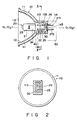
- Fig. 1 is a sectional view showing a lamp device according to an embodiment of the present invention;
- Fig. 2 is a sectional view of the lamp along the line II - II in Fig. 1;
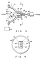
- Fig. 3 is a sectional view showing the step of injecting an adhesive to a half level so as to explain the first embodiment of a method of bonding the mirror reflector to the lamp;
- Fig. 4 is a sectional view of the lamp along the line IV - IV of Fig. 3;
- Fig. 5 is a sectional view showing the step of fully injecting the adhesive;
- Fig. 6 is a sectional view of the lamp along the line VI - VI of Fig. 5;
- Fig. 7 is a sectional view showing the step of injecting an adhesive to a half level so as to explain the second embodiment of a method of bonding the mirror reflector to the lamp;
- Fig. 8 is a sectional view of the lamp along the line VIII - VIII of Fig. 7;
- Fig. 9 is a sectional view showing the step of fully injecting the adhesive;
- Fig. 10 is a sectional view of the lamp along the line X - X of Fig. 9;
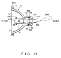
- Fig. 11 is a sectional view showing a lamp and a mirror reflector preliminarily bonded to each other by means a preliminary-bonding adhesive, and explaining the third embodiment of a method of bonding the mirror reflector to the lamp;
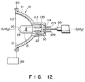
- Fig. 12 is a sectional view showing the step of injecting an adhesive to half level the gap between the lamp and the mirror reflector; and
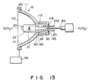
- Fig. 13 is a sectional view showing the step of full injecting the adhesive filling up the gap between the lamp and mirror reflector.
- Referring to Fig. 10,
reference numeral 10 denotes a mirror reflector. Themirror reflector 10 comprises areflector body 11 made of glass or a metal. - In this embodiment, the reflector body is made of glass. This
reflector body 11 has a reflector axis O1 - O1 and comprises a curved surface 111 having the reflector axis O1 - O1 as its center of revolution. The curved surface 111 is part of an ellipsoidal surface of revolution. - A
light projection portion 112 is open at one end portion, i.e., the front end portion of the quadratic surface 111 of revolution of thereflector body 11. Alamp mounting portion 113 extending along the direction of the reflector axis O1 - O1 is arranged at the other end portion, i.e., the rear end portion of the quadratic surface 111. - The
lamp mounting portion 113 integrally extends backward from the curved surface 111. Thelamp mounting portion 113 comprises a cylinder of a hollow structure. For example, thelamp mounting portion 113 has a rectangular parallelepiped hollow body. - The front and rear end portions of the
lamp mounting portion 113 are open. A rear end opening 114 has a rectangular opening having an area smaller than the sectional area of the mountingportion 113. - A
dichroic film 12 is formed on the inner surface of the curved surface 111 of thereflector body 11. Although thedichroic film 12 is known to those skilled in the art and is not illustrated in detail, thefilm 12 comprises a multilayered (17 to 21 layers) structure obtained by alternately stacking metal oxide films of a high refractive index such as TiO₂, ZrO₂, or ZnS, and metal oxide films of a low refractive index such as SiO₂ or MgF₂. Thedichroic film 12 having the above structure has the nature for reflecting visible light and transmitting infrared rays. That is, thedichroic film 12 is a kind of an optical interference film. - A
lamp 20 is mounted in themirror reflector 10. - The
lamp 20 comprises, for example, a halogen lamp, and comprises abulb 21 made of quartz glass. Thebulb 21 has a lamp axis O2 - O2 and a cylindrical shape along the lamp axis O2 - O2. Thebulb 21 has apinch sealing portion 22 at one end along the lamp axis O2 - O2. - An electrode means 23 is housed inside the
bulb 21 and comprises a filament, e.g., made of a tungsten coil. Both ends of thefilament 23 are connected to a pair ofinner wells 24. Theseinner wells 24 are connected to a pair of metal foils 25 made of Mo bonded to thepinch sealing portion 22. A pair ofouter wells 26 are connected to these metal foils 25, respectively. The pair ofouter wells 26 are guided outside from thepinch sealing portion 22 and are respectively connected to a pair of terminal means 271 and 272. The terminal means 271 and 272 are terminal pins. - The
halogen lamp 20 is bonded to themirror reflector 10 through an adhesive 30. - The adhesive 30 is a heat-resistant inorganic adhesive containing a metal oxide such as AℓO₂, SiO₂, MgO, or ZrO₂ as a major constituent and using water as a binder.
- The adhesive 30 is filled in a space between the sealing
portion 22 of thelamp 20 and the inner surface of thelamp mounting portion 113 of themirror reflector 10 to fix thelamp 20 and themirror reflector 10. - In this case, the lamp axis O2 - O2 is aligned with the reflector axis O1 - O1 of the
mirror 10, or is located close thereto within an allowable error range. The center of emission of the lamp is aligned with the focal position of themirror 10 or is located close thereto. In this position, the sealingportion 22 is inserted into the hollow portion of thelamp mounting portion 113 of thereflector body 11, and aspace 135 is formed between the outer surface of thelamp sealing portion 22 and the inner surface of thelamp mounting portion 113. The adhesive 30 is filled in thisspace 135. - A
space region 40 not filled with the adhesive 30 is formed inside thelamp mounting portion 113. Thespace region 40 is formed on the side of the ellipsoidal surface 111 within thelamp mounting portion 113 and is surrounded by the inner surface of thelamp mounting portion 113, the outer surface of the sealingportion 22 of the bulb, and the adhesive 30 filled therebetween. The front end of thespace region 40 is open toward thelight projection portion 112. - For this reason, the end portion of the
lamp mounting portion 113 on the side of the curved surface 111 is spaced apart from the sealingportion 22 of the bulb through the space. For this reason, thespace region 40 constitutes a heat-insulating space. - The adhesive 30 has a surface opposite to the
space region 40, i.e., afront end face 140 as an inclined surface. Thisinclined surface 140 is located within thelamp mounting portion 113, and an inclined surface portion bonded to thelamp mounting portion 113 further extends forward than that bonded to the sealingportion 22. - A surface of the adhesive 30 at a position opposite to the
other opening 114, i.e., arear end face 145, is recessed inward. - The terminal pins 271 and 272 extending from the sealing
portion 22 of thelamp 20 extend backward from the rear end face of thelamp mounting portion 113. - The terminal pins 271 and 272 are mechanically and electrically connected to a
socket 50. Thesocket 50 has a receiving metal piece (not shown), and theterminal pins - When the
terminal pins socket 50, thefilament 23 is electrically connected to the power source through the receiving metal piece. At the same time, the lamp with the mirror reflector is supported on thesocket 50. - An operation of the lamp with the mirror reflector having the above structure will be described below.
- When the
terminal pins filament 23, and thefilament 23 emits light. - Light emitted from the
filament 23 passes through thebulb 21 and reaches thedichroic film 12 formed on the curved surface 111 of thereflector body 11. Thedichroic film 12 reflects visible light components of the incident light and transmits infrared components having a wavelength of about 700 nm or more therethrough. - The visible light reflected by the
dichroic film 12 is projected forward from theoptical projection portion 112 of thereflector body 11 and illuminates an object such as an article. Since the light emitted from the lamp with the reflector has only a small amount of heat, and the temperature of the object such as an article is not increased, the object is not adversely affected by heat. - When the
filament 23 emits light, thefilament 23 is heated, and the heat is conducted from thefilament 23 to the sealingportion 22 through theinner wells 24. The temperature of the sealingportion 22 is increased. The infrared rays emitted from thefilament 23 cause an increase in temperature of the bulb wall. Heat is conducted from the bulb wall to the sealingportion 22 through the bulb wall, so that the temperature of the sealingportion 22 is increased. - In addition to this, since the
dichroic film 12 is formed on the reflecting surface in the lamp with the reflector, infrared rays are transmitted through thedichroic film 12 due to its optical interference. The infrared rays transmitted through thedichroic film 12 reach thereflector body 11 and heat thereflector body 11. The heat of thereflector body 11 is conducted to thelamp mounting portion 113 formed integrally therewith, thereby heating thelamp mounting portion 113. Heat of thelamp mounting portion 113 is conducted to the sealingportion 22 of the lamp through the adhesive 30. - According to the present invention, the
space region 40 not filled with the adhesive 30 is formed inside thelamp mounting portion 113, and thisspace region 40 constitutes a heat-insulating space. Therefore, conduction of heat of thelamp mounting portion 113 to the sealingportion 22 of the lamp is minimized. - More specifically, a portion of the
reflector body 11 having the highest temperature is a portion closest to thefilament 23 of the lamp. Heat of this high-temperature portion is conducted to thelamp mounting portion 113. An end portion, i.e., the front end portion of thelamp mounting portion 113 close to the curved surface 111 has the highest temperature. - To the contrary, since the
space region 40 is formed near the end of thelamp mounting portion 113 close to the curved surface 111, the high-temperature portion of thelamp mounting portion 113 is heat-insulated from the sealingportion 22 of the bulb through thespace region 40. Therefore, conduction of heat of thelamp mounting portion 113 to the sealingportion 22 of the lamp is minimized. - This allows suppression of a temperature rise of the sealing
portion 22 and prevention of a thermal stress of the sealingportion 22. - When a halogen lamp is used as the
lamp 20, a large amount of heat is dissipated from the lamp, and thereflector body 11 is rapidly heated. Therefore, a formation effect of thespace region 40 can be effectively enhanced. - Since the inwardly recessed
portion 145 is formed on a surface of the adhesive 30 opposite to theopening 114, i.e., the rear surface, when thelamp 20 is mounted in thesocket 50, a space is formed between the adhesive 30 and thesocket 50 through the recessedportion 145, conduction of heat of thelamp 20 to thesocket 50 is minimized. For this reason, damage to thesocket 50 due to heat can be prevented. - A method of bonding the
mirror reflector 10 to thelamp 20 will be described below. - The first embodiment of the bonding method will be described with reference to Figs. 3 to 6.
- The
reflector 10 having the above structure is supported by areflector chuck 60, and at the same time, thelamp 20 having the above structure is supported by alamp chuck 70. - The
reflector 10 is supported by themirror chuck 60 such that the mirror axis O1 - O1 is substantially horizontal, as shown in Fig. 3. Thelamp 20 is supported by thelamp chuck 70 such that the bulb axis O2 - O2 is substantially horizontal. Thelamp 20 is housed in thereflector 10, and the sealingportion 22 of thelamp 20 is inserted into thelamp mounting portion 113 of thereflector 10. In this state, thereflector 10 and thelamp 20 are respectively supported by thereflector chuck 60 and thelamp chuck 70 such that the bulb axis O2 - O2 is almost aligned with the mirror axis O1 - O1. - In this state of the
reflector 10 and thelamp 20, as shown in Fig. 4, the long sides of thelamp mounting portion 113 are vertically aligned since its sectional shape is a rectangular shape, and the longitudinal direction of thepinch sealing portion 22 of thelamp 20 is aligned in the vertical direction since theportion 22 is flat. The pair of terminal pins extending from the sealingportion 22 are supported such that oneterminal pin 271 is located at an upper position, and the otherterminal pin 272 is located at a lower position. - In this state, to say the
reflector 10 and thelamp 20 are respectively horizontally supported, when thereflector chuck 60 and thelamp chuck 70 are adjusted so that the center of emission of thelamp 20 is located at the focal position of thereflector 10 or has a predetermined positional relationship with the focal position. That is, the focusing relationship between thelamp 20 and thereflector 10 is adjusted. - An adhesive injection tool, e.g., a
nozzle 80 is inserted from the rear end opening 114 of thelamp mounting portion 113 of thereflector 10. Thenozzle 80 is connected to an adhesive supply unit through a hose (not shown), and the adhesive 30 is injected from the tip of thenozzle 80. - The tip of the
nozzle 80 is inserted into thelamp mounting portion 113 through therear end opening 114 and is aligned with the reflector axis O1 - O1. That is, the tip of thenozzle 80 is located between the pair of vertically alignedterminal pins - In this state, the heat-resistant
inorganic adhesive 30 is injected from thenozzle 80. At this time, the adhesive 30 has a viscosity of about 32,000 to 42,000 cps/25°C. When the adhesive 30 is injected as described above, the adhesive 30 injected from thenozzle 80 abuts against the sealingportion 22 of thelamp 20 and is sagged due to its weight and is filled in the lower portion of thespace 135 between the sealingportion 22 and the mountingportion 113. - When the adhesive 30 is supplied in an amount about half the required filling amount, the
mirror reflector 10 and thelamp 20 are reversed about the reflector axis O1 - O1 while their positional relationship is kept maintained, thenozzle 80 is kept inserted and the adhesive 30 is in a fluid state. - This pivotal movement is performed by pivoting the
reflector chuck 60 and thelamp chuck 70 by adrive unit 90. - The
reflector chuck 60 and thelamp chuck 70 are rotated together through 180°. Upon this pivotal movement, as is apparent from Fig. 6, the positions of the pair ofterminal pins - In this state, the remaining amount of the adhesive 30 is injected from the
nozzle 80. - The adhesive 30 injected from the
nozzle 80 abuts against the end face of the sealingportion 22, is sagged downward due to its weight, and is filled in the lower portion of thespace 135 between the sealingportion 22 and the mountingportion 113. - The upper space portion is filled with the previously filled adhesive 30, and the lower space portion is then filled with the subsequently filled adhesive 30. The adhesive 30 is thus filled in the entire space between the sealing
portion 22 of thelamp 20 and thelamp mounting portion 113 of thereflector 10. - When the adhesive 30 is injected from the
nozzle 80 as described above, the adhesive 30 is sagged by the gravitational force, so that the inclined surface is formed on thefront end face 140 of the adhesive 30. At the same time, the recessedportion 145 having a central recess is formed on the rear end face. - When filling of a predetermined amount of the adhesive 30 is completed, the
nozzle 80 is left inserted for a short period of time. After the adhesive 30 left in the distal end portion of thenozzle 80 is completely discharged to prevent formation of a droplet, thenozzle 80 is removed. - When the injection operation is completed, warm air is supplied from the front
light projection portion 112 of thereflector 10 and the rear end opening 114 of the mountingportion 113 to the mountingportion 113. This warm air is generated by a heater and a blower (neither are shown). - Since warm air is blown to the front and rear end faces 140 and 145 of the adhesive 30, the adhesive 30 is forcibly dried.
- The adhesive 30 is immediately hardened by this drying to bond the
mirror reflector 10 to thelamp 20. - According to the adhesive filling method described above, since the
adhesive injection nozzle 80 is inserted from the rear end opening 114 of thelamp mounting portion 113 of thereflector body 11, the adhesive 30 is not attached to the reflectingsurface 12 made of a dichroic film. Contamination of the reflectingsurface 12 with the adhesive can be prevented. Therefore, the adhesive need not be wiped out from the reflectingsurface 12, and degradation of the reflecting characteristics of the reflecting surface can be prevented. - Since the
nozzle 80 is inserted from the rear end opening 114 of thelamp mounting portion 113, theopening 114 is open wide. and thenozzle 80 can be easily inserted. The opening area of the injection port is kept large, and a predetermined amount of adhesive can be injected within a short period of time. At the same time, since a distance between therear end opening 114 and thespace 135 between the sealingportion 22 and thelamp mounting portion 113 is short, the adhesive injected from thenozzle 80 can be easily flowed into thespace 135, thereby shortening the injection time. - When the adhesive 30 is to be filled by the
nozzle 80, the positions of thereflector 10 and thelamp 20 are reversed. Therefore, the adhesive fills theentire space 135, and thenozzle 80 need not be shifted to another position for injection. In this manner, since the positions of thereflector 10 and thelamp 20 need only be reversed, an automatic injection operation can be performed. - Moreover, when a filling amount of the adhesive injected from the
nozzle 80 is selected to be an optimal amount, thespace region 40 can be easily formed. In addition, since the adhesive injected from thenozzle 80 flows by the gravitational force, the inclined surface can be formed as thefront end face 140 of the adhesive, and the recessedportion 145 having the central recess can be formed as the rear end face. - The second embodiment of a method of bonding a
mirror reflector 10 to alamp 20 will be described with reference to Figs. 7 to 10. - The bonding method of the second embodiment is substantially the same as that of the first embodiment except that the directions of the
mirror reflector 10 and thelamp 20 and a method of inserting anozzle 180 are different from those of the first embodiment. - In the second embodiment, the
mirror reflector 10 is horizontally held by areflector chuck 60, and thelamp 20 is horizontally held by alamp chuck 70, as shown in Fig. 7. Thelamp 20 is housed in thereflector 10, and a sealingportion 22 of thelamp 20 is inserted into alamp mounting portion 11 of thereflector 10. In this state, thereflector chuck 60 and thelamp chuck 70 support thereflector 10 and thelamp 20 such that a bulb axis O2 - O2 is almost aligned with a reflector axis O1 - O1. - In this case, as shown in Fig. 8, the positional relationship between the
reflector 10 and thelamp 20 is given such that a pair ofterminal pins portion 22 are located at the left and right positions and oppose each other in the horizontal direction. - The focal adjustment of the
lamp 20 and thereflector 10 will be performed in this state. - An
adhesive injection nozzle 180 is inserted from a rear end opening 114 of thelamp mounting portion 113. The tip of thenozzle 180 is inserted from the rear end opening 114 from the obliquely upward direction to the obliquely downward direction and is located between the pair ofterminal pins - In this state, a heat-resistant
inorganic adhesive 30 is injected from thenozzle 180. When the adhesive 30 is injected in an amount about half a total injection amount, thenozzle 180 is removed. - The vertical positions (right and left) of the
reflector 10 and thelamp 20 are reversed about the reflector axis O1 - O1 while the positional relationship between thereflector 10 and thelamp 20 is kept maintained. By this reversing operation, as is apparent from Figs. 9 and 10, the left and right positions of the pair ofterminal pins - In this state, the
nozzle 180 is inserted from the rear end opening 114, and the remaining amount of the adhesive 30 is injected. - The
space 135 between the sealingpotion 22 of thelamp 20 and thelamp mounting portion 113 is entirely filled with the previously filled adhesive 30 and the subsequently injected adhesive 30. - When filling of the adhesive 30 is completed, the
nozzle 180 is removed, and warm air is supplied from a frontlight projection portion 112 of thereflector 10 and the rear end opening 114 of the mountingportion 113 to dry the adhesive 30. - The
reflector 10 is then integrally bonded to thelamp 20 with the adhesive 30. - The third embodiment of a method of bonding a
mirror reflector 10 to alamp 20 will now be described with reference to Figs. 11 to 13. - The bonding method of the third embodiment is identical to that of the first embodiment, except that the position relation between the
reflector 10 and thelamp 20 is focus-adjusted, and thereflector 10 and the lamp are preliminarily bonded to each other. - More specifically, to bond the
mirror reflector 10 and thelamp 20 together, themirror reflector 10 and thelamp 20 are held by amirror chuck 600 and alamp chuck 700, respectively, as is illustrated in Fig. 11. Thechucks mirror chuck 600 or thelamp chuck 700, or both are slightly moved, thereby placing the light-emission center of thelamp 20 at the focal point of themirror reflector 10 or at a specific position with respect to the focal point of themirror reflector 10. In other words, themirror reflector 10 and thelamp 20 are focus-adjusted. - Then, a preliminary-
bonding nozzle 300 is inserted into thelamp mounting portion 113 of themirror reflector 10 through the rear end opening 114 of theportion 113. A preliminary-bonding adhesive 330 is supplied from thenozzle 300 into the gap between thelamp mounting portion 113 and the sealingportion 22 of thelamp 20. - The preliminary-
bonding adhesive 330 is, for example, an organic adhesive which hardens when irradiated with ultraviolet (UV) rays. It is desirable that the adhesive 330 be one which is combusted and decomposed into carbon dioxide when heated to 200°C or more. To preliminarily bond themirror reflector 10 and thelamp 20 together, it suffices to apply the adhesive 330 in a small amount, for example, 0.2 to 0.5 cc, and to apply the adhesive at two or three positions in the gap between thelamp mounting portion 113 and the sealingportion 22. - Thereafter, UV rays are applied through an optical fiber or the like onto the adhesive 300 preliminarily bonding the
mirror reflector 10 to thelamp 20. The intensity of these UV rays is 100 to 200 mmW, and the rays are applied for 1 to 3 seconds. As a result of this, the adhesive 330 quickly hardens. Hence, themirror reflector 10 and thelamp 20, both focus-adjusted, are preliminarily bonded to each other. - The focus adjustment, described above, can be performed after the adhesive 330 is applied, but before the adhesive hardened.
- Next, the
mirror reflector 10 is firmly bonded to thelamp 20 by means of thesame adhesive 30 as is used in the first and second embodiments. More precisely, as is shown in Fig. 12, themirror reflector 10 is held by themirror chuck 600. Thelamp 20 need not be held by thelamp chuck 700. This is because thelamp 20 is already integral with themirror reflector 10, and once thereflector 10 is held by thechuck 600, thelamp 20 is also held in place. - Then, as is shown in Fig. 12, a
nozzle 80 is inserted into the gap between thelamp mounting portion 113 and the sealingportion 22. This done, the adhesive 30 is applied into the gap from thenozzle 80, in about half the amount that should be filled in the gap. Then, adriver 90 is operated, thereby rotating themirror chuck 600 through 180° around the reflector axis O1 - O1 of themirror reflector 10, with thenozzle 80 kept inserted in thespace 135 between thelamp mounting portion 113 and the sealingportion 22. As a result, themirror reflector 10 and thelamp 20 are also rotated through 180°. - Thereafter, as is illustrated in Fig. 13, the remaining half of the adhesive 30 is applied from the
nozzle 80 into thegap 135 between thelamp mounting portion 113 and the sealingportion 22. Eventually, this adhesive 30 fills the upper half of thespace 135 between the sealingportion 22 and thelamp mounting portion 113, whereas the previously applied adhesive 30 fills the lower half of thespace 135. Hence, theentire space 135 is filled with the adhesive 30. - The unit consisting of the
mirror reflector 10 and thelamp 20 now integral with thereflector 10 is removed from themirror chuck 600. This unit is put into a heating/drying furnace (not shown). In the furnace, the unit is heated to 200°C or more, preferably about 300°C for 5 to 10 minutes. The adhesive 30 is, therefore, dries and hardened. As the unit is heated to 200°C or more, the adhesive 330, used for the provisional bonding of thereflector 10 and thelamp 20 and contained in the adhesive 30, is combusted and decomposed into carbon dioxide. The carbon dioxide is mostly expelled from the adhesive 30 which is hardening, but some carbon dioxide remains within the adhesive 30, in the form of pores. These pores are not so large as to impair the bonding force of the adhesive 30. - As the adhesive 30 dries and hardens in the heating/drying furnace, the
mirror reflector 10 is bonded firmly to thelamp 20. - As has been described, in the method of the third embodiment, the
mirror reflector 10 and thelamp 20 are held by thechucks reflector 10 and thelamp 20 are bonded preliminary, they need not be held by jigs to be set in a desired position relationship while the adhesive 30 is being applied into thespace 135 or drying and hardening in the furnace. In this respect, the method of the third embodiment is advantageous over those of the first and second embodiments, wherein thereflector 10 and thelamp 20 must be held by themirror chuck 60 and thelamp chuck 70, respectively, up until the adhesive 30 hardens completely. - Also, the method of the third embodiment is advantageous in that it suffices to hold either the
mirror reflector 10 or thelamp 20 while the adhesive 30 is drying and hardening in the heating/drying furnace. - It should be noted that the adhesive 330, which is used for bond the
reflector 10 and thelamp 20 preliminarily, is not limited to an UV-hardening, organic adhesive. Rather, the adhesive 330 can be an instantaneously hardening one, or can be one identical to the adhesive 30 used for firmly bonding the mirror reflector to thelamp 20. - Further, the adhesive 30 applied in the
space 135 can first be dried by blowing hot air onto thelamp mounting portion 113, before themirror reflector 10 and thelamp 20, provisionally bonded together, are placed in the heating/drying furnace, and then be hardened completely. - In the case where the adhesive 30 is dried and hardened in the heating/drying furnace, the adhesive 30 filled in the
lamp mounting portion 113 should better be dried preliminarily before themirror reflector 10 is brought into the heating/drying furnace. This preliminary drying is accomplished by applying hot air onto the front light-projectingportion 112 of thereflector 10 and simultaneously introducing the hot air into thelamp mounting portion 113 thereof through the rear end opening 114 of theportion 113. Hence, only the surface of theadhesive mass 30, i.e., only the front and rear faces 140 and 145, is dried and hardened. The preliminary drying prevents the adhesive 30 from flowing down when and after the unit consisting of thereflector 10 and thelamp 10, bonded together, is moved into the heating/drying furnace. - In each embodiment described above, the adhesive 30 is injected from the rear end opening 114 of the
lamp mounting portion 113 into thelamp mounting portion 113 by using thenozzle mirror reflector 10 and thelamp 20 are kept supported horizontally. However, themirror reflector 10 and thelamp 20 may be vertically supported or may be inclined. - In each embodiment described above, the
mirror reflector 10 and thelamp 20 are horizontally supported, and are intermittently reversed through 180°. However, themirror reflector 10 and thelamp 20 may be continuously rotated, or intermittently rotated every 60° or 90°. - As can be understood from the second bonding method shown in Figs. 7 to 10, the
nozzle 180 need not be located on the reflector axis O1 - O1. - The composition, viscosity, and hardening rate of the adhesive, and various characteristics such as the injection nozzle diameter, discharge pressure, and the like may be selected in consideration of an automatic injection operation of the adhesive and leakage to a portion except for the predetermined portion, and an optimal adhesive is selected in accordance with application purposes and practical applications.
- The first and second bonding methods are not limited to a mirror reflector having a dichroic film on its reflecting surface, but are applicable to a reflecting surface made of an aluminum film.
- The
lamp 20 is not limited to a halogen lamp, but may be replaced with an incandescent lamp, a wedge base type lamp, or a discharge lamp. - In a lamp with a mirror reflector according to the present invention, as has been described above, a space region not filled with an adhesive is surrounded by the inner surface of a lamp mounting portion, the outer surface of a sealing portion of the bulb, and the adhesive filled therebetween. The space region not filled with the adhesive minimizes conduction of heat of the heated reflector body during an ON operation of the lamp to the sealing portion of the lamp, thereby suppressing the temperature rise of the lamp sealing portion.
- According to the method of bonding the mirror reflector to the lamp of the present invention, since the adhesive is injected from the rear end opening of the lamp mounting portion to the lamp mounting portion by using an adhesive injection tool, the adhesive is not dropped or attached to the reflecting surface of the reflector. Since the adhesive is injected through the rear end opening of the lamp mounting portion, the distance between the opening of the lamp mounting portion and the sealing portion can be reduced. Therefore, the adhesive injection tool can be easily inserted, workability can be facilitated, and injection efficiency of the adhesive can be improved.
Claims (21)
a mirror reflector (10) including
a reflector body (11) having a reflector axis and a curved surface (111) and a lamp mounting portion (113) extending along a direction of the reflector axis at one end thereof, and said lamp mounting portion being constituted by a cylinder of a hollow structure open at an end corresponding to said curved surface and an end opposite thereto, and
an interference film (12), formed on at least an inner surface of said curved surface of said reflector body;
a lamp (20) including
a bulb (21) having a lamp axis and a sealing portion (22) at an end of the lamp axis,
electrode means (23) arranged inside said bulb, and
terminal means (271, 272) electrically connected to said electrode means and guided outside from said sealing portion;
an adhesive (30), filled in a space between an outer surface of said sealing portion and an inner surface of said lamp mounting portion while said sealing portion of said lamp is inserted in a hollow portion of said lamp mounting portion of said reflector body, for adhering said sealing portion to said lamp mounting portion; and
a space region (40) not filled with said adhesive, said space region being located inside said lamp mounting portion and surrounded by said inner surface of said lamp mounting portion, said outer surface of said sealing portion, and said adhesive filled therebetween, said space region being open on an end thereof corresponding to said curved surface, thereby preventing heat conduction between said lamp mounting portion and said sealing portion.
a mirror reflector (10) including
a reflector body (11) having a reflector axis and a curved surface (111) and a lamp mounting portion (113) extending along a direction of the reflector axis at one end thereof, and said lamp mounting portion being constituted by a cylinder of a hollow structure open at an end corresponding to said curved surface and an end opposite thereto, and
a light-reflecting surface (12) formed on at least an inner surface of said reflector body;
a lamp (20) including
a bulb (21) having a lamp axis and a sealing portion (22) at an end of the lamp aixs,
electrode means (23) arranged inside said bulb, and
terminal means (271, 272) electrically connected to said electrode means and guided outside from said sealing portion; and
an adhesive (30), filled in a space between an outer surface of said sealing portion and an inner surface of said lamp mounting portion while said sealing portion of said lamp is inserted in a hollow portion of said lamp mounting portion of said reflector body, for adhering said sealing portion to said lamp mounting portion, characterized by comprising the steps of:
inserting said sealing portion of said lamp into said lamp mounting portion of said reflector body while an axis of said lamp is substantially aligned with an axis of said mirror reflector, and holding said mirror reflector and said lamp while assuring a space between said outer surface of said sealing portion and said inner surface of said lamp mounting portion; and
injecting said adhesive from said opening of said lamp mounting portion at said end opposite to said curved surface toward said lamp mounting portion by using an adhesive injection tool, and filling said adhesive in the space between said outer surface of said sealing portion and said inner surface of said lamp mounting portion.
holding said mirror reflector and said lamp in horizontal position so that the axis of said lamp is substantially aligned with the axis of said reflector, inserting said sealing portion of said lamp into said lamp mounting portion of said mirror reflector, and forming a space between said outer surface of said sealing portion and said inner surface of said lamp mounting portion; and
injecting said adhesive from said opening of said lamp mounting portion opposite to said curved surface to said lamp mounting portion by using an adhesive injection tool, and filling said adhesive in the space between said outer surface of said sealing portion and said inner surface of said lamp mounting portion.
Applications Claiming Priority (6)
| Application Number | Priority Date | Filing Date | Title |
|---|---|---|---|
| JP251021/89 | 1989-09-27 | ||
| JP25102189A JPH03112051A (en) | 1989-09-27 | 1989-09-27 | Connecting method for reflecting mirror and lamp |
| JP251020/89 | 1989-09-27 | ||
| JP25102089A JPH03112050A (en) | 1989-09-27 | 1989-09-27 | Connecting method for reflecting mirror and lamp |
| JP30297/90 | 1990-02-09 | ||
| JP3029790A JPH03236154A (en) | 1990-02-09 | 1990-02-09 | Connecting method for reflecting mirror and lamp |
Publications (2)
| Publication Number | Publication Date |
|---|---|
| EP0420214A2 true EP0420214A2 (en) | 1991-04-03 |
| EP0420214A3 EP0420214A3 (en) | 1991-08-28 |
Family
ID=27286912
Family Applications (1)
| Application Number | Title | Priority Date | Filing Date |
|---|---|---|---|
| EP19900118509 Withdrawn EP0420214A3 (en) | 1989-09-27 | 1990-09-26 | Lamp device and method of bonding mirror reflector to lamp |
Country Status (3)
| Country | Link |
|---|---|
| US (1) | US5178712A (en) |
| EP (1) | EP0420214A3 (en) |
| KR (1) | KR910006661A (en) |
Cited By (3)
| Publication number | Priority date | Publication date | Assignee | Title |
|---|---|---|---|---|
| EP1005061A1 (en) * | 1998-11-26 | 2000-05-31 | Phoenix Electric Co., Ltd. | Halogen lamp with reflector |
| EP1271051A3 (en) * | 2001-06-28 | 2004-09-01 | Sirrah S.r.l. | Dichroic lamp with improved diffusion of light radiation |
| EP1995513A1 (en) * | 2007-05-22 | 2008-11-26 | Goodrich Lighting Systems GmbH | Method for mounting an LED |
Families Citing this family (7)
| Publication number | Priority date | Publication date | Assignee | Title |
|---|---|---|---|---|
| US5928468A (en) * | 1995-10-18 | 1999-07-27 | Tolson; John Thomas | High pressure glue injection device |
| US6217581B1 (en) | 1995-10-18 | 2001-04-17 | John Thomas Tolson | High pressure cement injection device for bone repair |
| US6212004B1 (en) | 1996-05-10 | 2001-04-03 | Applied Coatings, Inc. | Reflector with directional control of visible and infra-red radiation |
| MXPA02003659A (en) * | 1999-10-15 | 2003-05-23 | Siemens Canada Ltd | Method to create a hot melt form for use with an air induction assembly. |
| JP4155258B2 (en) * | 2004-02-10 | 2008-09-24 | セイコーエプソン株式会社 | LAMP DEVICE, ITS MANUFACTURING METHOD, AND PROJECTOR HAVING LAMP DEVICE |
| JP4752951B2 (en) * | 2009-05-29 | 2011-08-17 | ウシオ電機株式会社 | Incandescent light bulb and light source device |
| DK2734658T3 (en) * | 2011-07-20 | 2019-09-16 | New Nel Hydrogen As | Framework concept for electrolyzer, method and application |
Citations (7)
| Publication number | Priority date | Publication date | Assignee | Title |
|---|---|---|---|---|
| DE452751C (en) * | 1926-03-31 | 1927-11-18 | Patra Patent Treuhand | Method for cementing the bases of electric light bulbs, discharge tubes and similar glass vessels made of insulating material |
| US3314331A (en) * | 1965-04-29 | 1967-04-18 | Gen Electric | Photographic projection system and lamp |
| US4021659A (en) * | 1975-10-30 | 1977-05-03 | General Electric Company | Projector lamp reflector |
| EP0061750A2 (en) * | 1981-03-30 | 1982-10-06 | GTE Products Corporation | Projection unit including glass reflector with insulative cap member |
| US4608624A (en) * | 1985-01-22 | 1986-08-26 | Gte Products Corporation | Projection lamp unit with separable lamp capsule |
| EP0277659A2 (en) * | 1987-02-05 | 1988-08-10 | Gte Products Corporation | Electric lamp, base for use therewith and method of assembling same |
| EP0309750A2 (en) * | 1987-09-29 | 1989-04-05 | General Electric Company | Aluminum phosphate cement compositions and lamp assemblies containing same |
Family Cites Families (6)
| Publication number | Priority date | Publication date | Assignee | Title |
|---|---|---|---|---|
| NL156827B (en) * | 1967-02-01 | 1978-05-16 | Philips Nv | PROJECTION UNIT, CONSISTING OF A CONDENSER MIRROR AND A HALOGEN BULB. |
| US4169238A (en) * | 1978-09-06 | 1979-09-25 | Gte Sylvania Incorporated | Movie light, low voltage incandescent lamp unit for use therewith, and reflector |
| US4482942A (en) * | 1981-03-30 | 1984-11-13 | Gte Products Corporation | Projection unit including glass reflector with insulative cap member |
| JPS59184750A (en) * | 1983-04-05 | 1984-10-20 | Shibata Hario Glass Kk | Production of double wall vessel |
| US4785383A (en) * | 1985-06-03 | 1988-11-15 | General Electric Company | Lamp unit having glass reflector member with mount structure |
| US5023031A (en) * | 1985-06-11 | 1991-06-11 | Bradford-White Corporation | Method of making a foam insulated water heater |
-
1990
- 1990-09-26 EP EP19900118509 patent/EP0420214A3/en not_active Withdrawn
- 1990-09-27 US US07/588,991 patent/US5178712A/en not_active Expired - Fee Related
- 1990-09-27 KR KR1019900015335A patent/KR910006661A/en not_active Application Discontinuation
Patent Citations (7)
| Publication number | Priority date | Publication date | Assignee | Title |
|---|---|---|---|---|
| DE452751C (en) * | 1926-03-31 | 1927-11-18 | Patra Patent Treuhand | Method for cementing the bases of electric light bulbs, discharge tubes and similar glass vessels made of insulating material |
| US3314331A (en) * | 1965-04-29 | 1967-04-18 | Gen Electric | Photographic projection system and lamp |
| US4021659A (en) * | 1975-10-30 | 1977-05-03 | General Electric Company | Projector lamp reflector |
| EP0061750A2 (en) * | 1981-03-30 | 1982-10-06 | GTE Products Corporation | Projection unit including glass reflector with insulative cap member |
| US4608624A (en) * | 1985-01-22 | 1986-08-26 | Gte Products Corporation | Projection lamp unit with separable lamp capsule |
| EP0277659A2 (en) * | 1987-02-05 | 1988-08-10 | Gte Products Corporation | Electric lamp, base for use therewith and method of assembling same |
| EP0309750A2 (en) * | 1987-09-29 | 1989-04-05 | General Electric Company | Aluminum phosphate cement compositions and lamp assemblies containing same |
Cited By (4)
| Publication number | Priority date | Publication date | Assignee | Title |
|---|---|---|---|---|
| EP1005061A1 (en) * | 1998-11-26 | 2000-05-31 | Phoenix Electric Co., Ltd. | Halogen lamp with reflector |
| EP1271051A3 (en) * | 2001-06-28 | 2004-09-01 | Sirrah S.r.l. | Dichroic lamp with improved diffusion of light radiation |
| EP1995513A1 (en) * | 2007-05-22 | 2008-11-26 | Goodrich Lighting Systems GmbH | Method for mounting an LED |
| US8006376B2 (en) | 2007-05-22 | 2011-08-30 | Goodrich Lighting Systems Gmbh | Method for assembly of an LED light |
Also Published As
| Publication number | Publication date |
|---|---|
| KR910006661A (en) | 1991-04-29 |
| US5178712A (en) | 1993-01-12 |
| EP0420214A3 (en) | 1991-08-28 |
Similar Documents
| Publication | Publication Date | Title |
|---|---|---|
| EP0420214A2 (en) | Lamp device and method of bonding mirror reflector to lamp | |
| EP0588602B1 (en) | Vehicle headlamp | |
| KR930003953B1 (en) | Xenon metal halide lamp having an improved electrode structure | |
| US5184044A (en) | Dental curing lamp | |
| EP0516231B1 (en) | Electric reflector lamp | |
| JPS6112695B2 (en) | ||
| JPH02172102A (en) | Centralized lighting system using high-luminance light source | |
| JPH02148603A (en) | Head lamp for vehicle | |
| US5168193A (en) | Lamp having boron nitride reflective coating | |
| JP2003308709A (en) | Par lamp device | |
| JPH1050254A (en) | Arc discharge light source | |
| KR100638934B1 (en) | Electric incandescent lamp | |
| JP2006524885A (en) | Infrared radiator and lighting device | |
| KR100503981B1 (en) | electric incandescent lamp | |
| US4534742A (en) | Method and apparatus for dispensing small quantities of mercury from evacuated and sealed glass capsules | |
| JPH05205698A (en) | Electric light equipped with lens in light-emitting chamber | |
| US4174487A (en) | Mirror condenser lamp | |
| US8247972B2 (en) | Ceramic discharge lamp with integral burner and reflector | |
| CN1707745B (en) | Method and apparatus for producing a lamp | |
| JPH03236154A (en) | Connecting method for reflecting mirror and lamp | |
| JP2004022452A (en) | Short arc type discharge lamp | |
| JP4159134B2 (en) | Alignment method for illumination light source | |
| JPH03112050A (en) | Connecting method for reflecting mirror and lamp | |
| JPH10188920A (en) | Bulb with reflecting mirror, and luminaire | |
| JPH05251062A (en) | Incandescent bulb with reflecting mirror |
Legal Events
| Date | Code | Title | Description |
|---|---|---|---|
| PUAI | Public reference made under article 153(3) epc to a published international application that has entered the european phase |
Free format text: ORIGINAL CODE: 0009012 |
|
| 17P | Request for examination filed |
Effective date: 19901023 |
|
| AK | Designated contracting states |
Kind code of ref document: A2 Designated state(s): DE GB |
|
| PUAL | Search report despatched |
Free format text: ORIGINAL CODE: 0009013 |
|
| AK | Designated contracting states |
Kind code of ref document: A3 Designated state(s): DE GB |
|
| RHK1 | Main classification (correction) |
Ipc: H01J 61/02 |
|
| 17Q | First examination report despatched |
Effective date: 19921125 |
|
| STAA | Information on the status of an ep patent application or granted ep patent |
Free format text: STATUS: THE APPLICATION IS DEEMED TO BE WITHDRAWN |
|
| 18D | Application deemed to be withdrawn |
Effective date: 19930406 |