EP0420657B1 - Moving object detecting system - Google Patents
Moving object detecting system Download PDFInfo
- Publication number
- EP0420657B1 EP0420657B1 EP90310621A EP90310621A EP0420657B1 EP 0420657 B1 EP0420657 B1 EP 0420657B1 EP 90310621 A EP90310621 A EP 90310621A EP 90310621 A EP90310621 A EP 90310621A EP 0420657 B1 EP0420657 B1 EP 0420657B1
- Authority
- EP
- European Patent Office
- Prior art keywords
- features
- image
- background
- feature
- region
- Prior art date
- Legal status (The legal status is an assumption and is not a legal conclusion. Google has not performed a legal analysis and makes no representation as to the accuracy of the status listed.)
- Expired - Lifetime
Links
Images


Classifications
-
- G—PHYSICS
- G06—COMPUTING; CALCULATING OR COUNTING
- G06T—IMAGE DATA PROCESSING OR GENERATION, IN GENERAL
- G06T7/00—Image analysis
- G06T7/20—Analysis of motion
- G06T7/246—Analysis of motion using feature-based methods, e.g. the tracking of corners or segments
Definitions
- One of the important techniques for realizing a state monitor apparatus, a mobile robot, or the like is a technique for detecting a moving object in a given environment from environmental image frames from moment to moment obtained by an imaging system which is movable.
- This technique for detecting the moving object from a moving image is based on a so-called motion analysis.
- extensive studies have been made on this detection technique in the fields of computer visions. This technique, however, is not applied to practical apparatuses or field works.
- the invention provides a system and method as defined respectively in claims 1 and 13 below.
- the moving object detecting system estimates a region where features detected from image frames obtained by the mobile imaging system may have been present at immediately preceding moments (if a given feature belongs to the background) on the basis of the prediction parameters and detects whether a feature corresponding to the given feature belongs to the estimated region of presence, thereby detecting the presence/absence of the moving object.
- the prediction parameters are estimated from motion of the known background at the start of movement of the mobile imaging system. On the basis of the prediction parameters, those positions in the immediately preceding frame which correspond to the respective features obtained from the moving image frame are estimated, and only those features which do not have corresponding features at the estimated positions in the immediately preceding frame are extracted. Therefore, the moving object in the moving image can be efficiently, accurately searched at high speed.
- the image input section 1 comprises an imaging system mounted on a moving system such as a mobile robot and momently image frames and inputs moving environmental image frames to the system. Upon movement of the moving system, frames of image information sequentially imaged and input from the image input section whose imaging position is sequentially changed are supplied to the feature extracting section 2.
- the feature extracting section 2 sequentially extracts regions having large spatial differential values as features.
- the moving object detecting system is used to efficiently detect a moving object (an image component except for the background) from environmental image frames accompanying displacements of image information in the background.
- Feature detection information is supplied to the feature position detecting circuit 23, and the position of the feature on the image is calculated. Pieces of feature detection position information are sequentially stored as a feature table in the feature table memory 24.
- This feature detection processing is performed in units of image frames sequentially obtained and stored in the image memory 15. Pieces of feature detection position information obtained from each image are classified, and the classified pieces of information are written in the feature table.
- a portion corresponding to the background feature detecting section 3 comprises an image monitor 31, a region designating circuit 32, a feature detecting circuit 33, and a background feature table memory 34.
- the feature detecting circuit 33 selectively extracts features belonging to the designated background region. Pieces of feature information thus obtained are stored in the background feature table memory 34 as background feature table information serving as the basis of feature correlation processing.
- This background feature detection processing is similarly performed for the next frame image obtained upon the start of movement, and the obtained information is stored in the background feature table memory 34.
- a portion corresponding to the prediction parameter calculating section 4 comprises a feature selecting circuit 41, a prediction parameter calculating circuit 42, and a prediction parameter table memory 43.
- the feature selecting circuit 41 correlates the background features in an image frame obtained at the start of movement and stored in the background feature table in the background feature table memory 34 and the background features in an image frame obtained upon the start of movement under the assumption that a large change does not occur between these image frames. It is also possible to interactively correlate the background features by using the image monitor 31 and the region designating circuit 32.
- the prediction parameter calculating circuit 42 calculates parameters representing a displacement of the background on the image in accordance with the displacement of the moving system, i.e., displacement of the imaging system (the ITV camera 11 in the image input section) which causes displacements of features in accordance with a positional relationship between the correlated background features between the two image frames obtained at the time of movement and upon the start of movement. The obtained parameters are written in a prediction parameter table stored in the prediction parameter table memory 43.
- a translational component of a motion of the imaging system is given as: (-T X , -T Y , -T Z ) and its rotational component is given as: (- ⁇ X , - ⁇ Y , - ⁇ Z )
- the fifteen parameters A to O have the following meanings:
- the fifteen prediction parameters A to O correlate the background features of two image frames (at least eight features of each image) at the time of movement and upon the start of movement of the imaging system under the assumption that a Z initial value (i.e., a distance between the background and the imaging system prior to movement) is known. These pieces of position information are substituted to obtain the correlated background features.
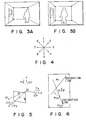
- This equation represents a line.
- Equation (4) representing the line indicates that a point P t (x t , y t ) in the immediately preceding frame is present in the region (estimated line) represented by equation (4) if the feature P t+1 (x t+1 , y t+1 ) in the image belongs to a stationary object with respect to the environment.
- the line represented by equation (4) in the immediately preceding frame is searched to determine whether the corresponding feature is present, thereby determining whether the feature belongs to the stationary object with respect to the environment. That is, when the corresponding feature is present on the line represented by equation (4), the feature of interest belongs to the stationary background object with respect to the environment. However, when the feature corresponding to the feature of interest is not present, the feature of interest belongs to a new object which is not the background.
- the estimation line coefficient calculating circuit 51 constituting a portion corresponding to the estimation line calculating portion 5 obtains position information of the feature extracted from the moving image frame in accordance with the feature table in the feature table memory 24 and calculates the coefficients ⁇ , ⁇ , ⁇ , and ⁇ in accordance with the 15 prediction parameters stored in the prediction parameter table memory 43, thereby obtaining an estimation line representing the region in which each feature belongs.
- a portion corresponding to the feature searching section 6 comprises a feature candidate selecting circuit 61, a similarity calculating circuit 62, a feature determining circuit 63, and a moving object candidate table 64.
- the feature determining circuit 63 compares the obtained similarity with a predetermined threshold value and determines whether the image features are sufficiently similar to each other. That is, the correlated features are defined as similar image features from all the features of the image of the immediately preceding frame. Feature for which correlated features cannot be detected in the immediately preceding frame by this determination processing are determined to be new features. The information of such new features is stored as a moving body candidate table in the moving body candidate table 64.
- a portion corresponding to the moving body determining section 7 comprises a neighboring feature detecting circuit 71 and a moving object determining circuit 72.
- the moving object detecting system of the present invention regularity of motion of the background upon movement of the imaging system is taken into consideration.
- the region of movement of features upon movement of the imaging system is estimated to obtain feature correlation between a plurality of image frames.
- the region of movement of the features is estimated as a line region in accordance with the prediction parameters determined on the basis of the motion data of the background in the initial image frames. For this reason, the moving object can be accurately and quickly detected by very simple processing for verifying whether features corresponding to the prediction region on the line are present.
- the moving object in the image can be efficiently detected as information of features which cannot be correlated while background features correlated to the estimation line are sequentially excluded from the image frames sequentially obtained by the mobile imaging system.
- this technique is very effective to realize a mobile robot or the like.
- the present invention is not limited to the particular embodiment described above.
- the prediction parameters can be much simplified, and the operations required for calculating a prediction line are further simplified.
- a processing speed can be increased.
Description

Claims (13)
- A moving object detecting system comprising:characterized by including:image acquiring means (1;11-15), having an imaging system (11-13), for acquiring image frames sequentially obtained by said imaging system (11-13);feature extracting means (2;21-24) for extracting features of each image frame acquired by said image acquiring means (1;11-15); and background feature detecting means (3;31-34) for detecting background features belonging to a background region of the image frame from the features extracted by said feature extracting means (2;21-24);prediction parameter calculating means (4;41-43) for obtaining prediction parameters for predicting a motion of the background region in the image frame upon movement of said imaging system (11-13) in accordance with a positional relationship between the correlated background features, between a plurality of image frames, on the basis of the background features detected by said background feature detecting means (3; 31-34);region estimating means (5; 51), for estimating a region of a given feature corresponding to the feature of an image frame of an immediately preceding frame by using the prediction parameters obtained by said prediction parameter calculating means (4;41-43) when the given feature detected from the image frame obtained by said imaging system (11-13), is assumed as a feature belonging to a background; andmoving object determining means (6, 7; 61-64, 71, 72) for determining whether a feature corresponding to the given feature is present in the estimation region obtained by said region estimating means (5; 51);wherein said background feature detecting means (3;31-34) includes means (31) for displaying an image, operator means (32) for designating the background region in the image displayed by said image displaying means, and means (33) for detecting the features belonging to the background region designated by said operator means as the background features.
- A system according to claim 1, characterized in that said imaging system (11-13) includes a television camera (11).
- A system according to claim 1, characterized in that said imaging system (11-13) is mounted on a moving unit.
- A system according to claim 3, characterized in that said image acquiring means (1;11-15) comprises means (11-13) for acquiring image frames sequentially obtained with movement of said imaging system (11-13).
- A system according to claim 1, characterized in that said feature extracting means (2;21-24) includes means (21-23) for calculating spatial differential values of image information in a plurality of directions and extracting portions having larger spatial differential values than a predetermined value as features.
- A system according to claim 1, characterized in that said background feature detecting means (3;31-34) includes means (33) for detecting the background features belonging to a background region from the features of the plurality of image frames.
- A system according to claim 1, characterized in that said prediction parameter calculating means (4;41-43) includes means (42) for calculating the prediction parameter on the basis of a plurality of image frames at the start of movement.
- A system according to claim 1, characterized in that said prediction parameter calculating means (4;41-43) includes means (41) for determining whether features are correlated to each other on the basis of a similarity between image patterns near the given feature.
- A system according to claim 1, characterized in that said prediction parameter calculating means (4;31, 32,41-43) includes means (31) for displaying an image, means (32) for designating correlated features in a plurality of image frames displayed by said image displaying means, and means (41) for detecting the features of the plurality of image frames designated by said designating means as the correlated features.
- A system according to claim 1, characterized in that said region estimating means (5;51) includes means (5;51) for estimating the region as a line region.
- A system according to claim 1, characterized in that said moving object determining means (6, 7; 61-64, 71, 72) includes means (61) for determining that features for which correlated features are not present in the region are defined as new features.
- A system according to claim 11, characterized in that said moving object determining means (6,7;61-64,71,72) includes means (61) for determining whether features belong to the moving object on the basis of the correlation of the new features between a plurality of image frames.
- A method of detecting a moving object comprising the steps:characterized by the steps of:acquiring image frames sequentially by means of an imaging system (11-13);extracting features of each acquired image frame; anddetecting background features belonging to a background region of the image frame from the extracted features;obtaining prediction parameters for predicting a motion of the background region in the image frame upon movement of said imaging system (11-13) in accordance with a positional relationship between the correlated background features between a plurality of image frames on the basis of the background features;estimating a region of a given feature corresponding to the feature of an image frame of an immediately preceding frame by using the prediction parameters when the given feature detected from the image frame obtained by said imaging system (11-13) is assumed as a feature belonging to a background; anddetermining whether a feature corresponding to the given feature is present in the estimation region; and whereinthe step of detecting the background feature includes displaying an image, interactively designating the background region in the displayed image, and detecting the features belonging to the designated background region as the background features.
Applications Claiming Priority (2)
| Application Number | Priority Date | Filing Date | Title |
|---|---|---|---|
| JP1249071A JP2953712B2 (en) | 1989-09-27 | 1989-09-27 | Moving object detection device |
| JP249071/89 | 1989-09-27 |
Publications (3)
| Publication Number | Publication Date |
|---|---|
| EP0420657A2 EP0420657A2 (en) | 1991-04-03 |
| EP0420657A3 EP0420657A3 (en) | 1993-12-22 |
| EP0420657B1 true EP0420657B1 (en) | 1998-03-18 |
Family
ID=17187574
Family Applications (1)
| Application Number | Title | Priority Date | Filing Date |
|---|---|---|---|
| EP90310621A Expired - Lifetime EP0420657B1 (en) | 1989-09-27 | 1990-09-27 | Moving object detecting system |
Country Status (5)
| Country | Link |
|---|---|
| US (1) | US5103305A (en) |
| EP (1) | EP0420657B1 (en) |
| JP (1) | JP2953712B2 (en) |
| CA (1) | CA2026290C (en) |
| DE (1) | DE69032146T2 (en) |
Families Citing this family (74)
| Publication number | Priority date | Publication date | Assignee | Title |
|---|---|---|---|---|
| US6772057B2 (en) | 1995-06-07 | 2004-08-03 | Automotive Technologies International, Inc. | Vehicular monitoring systems using image processing |
| US6856873B2 (en) | 1995-06-07 | 2005-02-15 | Automotive Technologies International, Inc. | Vehicular monitoring systems using image processing |
| US6442465B2 (en) * | 1992-05-05 | 2002-08-27 | Automotive Technologies International, Inc. | Vehicular component control systems and methods |
| US5663879A (en) * | 1987-11-20 | 1997-09-02 | North American Philips Corporation | Method and apparatus for smooth control of a vehicle with automatic recovery for interference |
| JP2921936B2 (en) * | 1990-07-13 | 1999-07-19 | 株式会社東芝 | Image monitoring device |
| EP0488723B1 (en) * | 1990-11-30 | 1997-02-26 | Canon Kabushiki Kaisha | Movement vector detection apparatus |
| US5590217A (en) * | 1991-04-08 | 1996-12-31 | Matsushita Electric Industrial Co., Ltd. | Vehicle activity measuring apparatus |
| FR2680931B1 (en) * | 1991-08-27 | 1997-08-14 | Thomson Csf | METHOD FOR DETECTING AND TRACKING MOVING OBJECTS BY ANALYSIS OF IMAGE SEQUENCES. |
| JPH06101018B2 (en) * | 1991-08-29 | 1994-12-12 | インターナショナル・ビジネス・マシーンズ・コーポレイション | Search of moving image database |
| US5619593A (en) * | 1991-09-12 | 1997-04-08 | Fuji Photo Film Co., Ltd. | Method for extracting object images and method for detecting movements thereof |
| JP2873338B2 (en) * | 1991-09-17 | 1999-03-24 | 富士通株式会社 | Moving object recognition device |
| EP0557007A2 (en) * | 1992-02-15 | 1993-08-25 | Sony Corporation | Picture processing apparatus |
| US5706417A (en) * | 1992-05-27 | 1998-01-06 | Massachusetts Institute Of Technology | Layered representation for image coding |
| EP0590759B1 (en) * | 1992-08-12 | 1998-12-09 | International Business Machines Corporation | System and method for locating video segment boundaries |
| USRE38420E1 (en) * | 1992-08-12 | 2004-02-10 | British Broadcasting Corporation | Derivation of studio camera position and motion from the camera image |
| GB2270436A (en) * | 1992-09-05 | 1994-03-09 | Ibm | Target tracking system |
| DE4311972A1 (en) * | 1993-04-10 | 1994-10-13 | Bosch Gmbh Robert | Process for the detection of changes in moving images |
| KR950002458A (en) * | 1993-06-02 | 1995-01-04 | 이헌조 | Video signal compression / extension device |
| US5687249A (en) * | 1993-09-06 | 1997-11-11 | Nippon Telephone And Telegraph | Method and apparatus for extracting features of moving objects |
| US5434927A (en) * | 1993-12-08 | 1995-07-18 | Minnesota Mining And Manufacturing Company | Method and apparatus for machine vision classification and tracking |
| JP3450449B2 (en) * | 1994-07-18 | 2003-09-22 | キヤノン株式会社 | Imaging device and imaging method thereof |
| US5889878A (en) * | 1994-07-29 | 1999-03-30 | Kabushiki Kaisha Toshiba | Moving object image pickup apparatus |
| KR100287211B1 (en) * | 1994-08-30 | 2001-04-16 | 윤종용 | Bidirectional motion estimation method and system |
| JP3569992B2 (en) * | 1995-02-17 | 2004-09-29 | 株式会社日立製作所 | Mobile object detection / extraction device, mobile object detection / extraction method, and mobile object monitoring system |
| US6493031B1 (en) * | 1995-03-31 | 2002-12-10 | Canon Kabushiki Kaisha | Visual information processing method and apparatus for extracting feature quantities from a two-dimensional image signal |
| US5654771A (en) * | 1995-05-23 | 1997-08-05 | The University Of Rochester | Video compression system using a dense motion vector field and a triangular patch mesh overlay model |
| US5854856A (en) * | 1995-07-19 | 1998-12-29 | Carnegie Mellon University | Content based video compression system |
| US5959673A (en) * | 1995-10-05 | 1999-09-28 | Microsoft Corporation | Transform coding of dense motion vector fields for frame and object based video coding applications |
| US5774591A (en) * | 1995-12-15 | 1998-06-30 | Xerox Corporation | Apparatus and method for recognizing facial expressions and facial gestures in a sequence of images |
| FR2742901B1 (en) * | 1995-12-22 | 1998-02-13 | Thomson Multimedia Sa | CORRECTION METHOD OF MOTION ESTIMATION IN IMAGES WITH PERIODIC STRUCTURES |
| DE19601005A1 (en) * | 1996-01-15 | 1997-07-17 | Bosch Gmbh Robert | Process for the detection of moving objects in successive images |
| US6037988A (en) * | 1996-03-22 | 2000-03-14 | Microsoft Corp | Method for generating sprites for object-based coding sytems using masks and rounding average |
| US5767922A (en) * | 1996-04-05 | 1998-06-16 | Cornell Research Foundation, Inc. | Apparatus and process for detecting scene breaks in a sequence of video frames |
| US6075875A (en) * | 1996-09-30 | 2000-06-13 | Microsoft Corporation | Segmentation of image features using hierarchical analysis of multi-valued image data and weighted averaging of segmentation results |
| US6351565B1 (en) * | 1997-02-07 | 2002-02-26 | Matsushita Electric Industrial Co, Ltd. | Data structure for image transmission, method of image transmission, image decoding apparatus, and data recording media |
| JP3384314B2 (en) * | 1997-12-02 | 2003-03-10 | ヤマハ株式会社 | Tone response image generation system, method, apparatus, and recording medium therefor |
| US6400831B2 (en) | 1998-04-02 | 2002-06-04 | Microsoft Corporation | Semantic video object segmentation and tracking |
| US6711278B1 (en) * | 1998-09-10 | 2004-03-23 | Microsoft Corporation | Tracking semantic objects in vector image sequences |
| US6466205B2 (en) * | 1998-11-19 | 2002-10-15 | Push Entertainment, Inc. | System and method for creating 3D models from 2D sequential image data |
| JP4146955B2 (en) * | 1999-02-15 | 2008-09-10 | キヤノン株式会社 | Image processing method and image processing apparatus |
| US6754367B1 (en) * | 1999-09-30 | 2004-06-22 | Hitachi Denshi Kabushiki Kaisha | Method and apparatus for automatically detecting intrusion object into view of image pickup device |
| US6826292B1 (en) * | 2000-06-23 | 2004-11-30 | Sarnoff Corporation | Method and apparatus for tracking moving objects in a sequence of two-dimensional images using a dynamic layered representation |
| US7386170B2 (en) * | 2000-06-30 | 2008-06-10 | Texas Instruments Incorporated | Image object ranking |
| US6778705B2 (en) * | 2001-02-27 | 2004-08-17 | Koninklijke Philips Electronics N.V. | Classification of objects through model ensembles |
| JP4187448B2 (en) | 2002-03-07 | 2008-11-26 | 富士通マイクロエレクトロニクス株式会社 | Method and apparatus for tracking moving object in image |
| US6983020B2 (en) * | 2002-03-25 | 2006-01-03 | Citrix Online Llc | Method and apparatus for fast block motion detection |
| US7634111B2 (en) | 2002-07-30 | 2009-12-15 | Sony Corporation | Storage device, signal processor, image signal processor, and their methods |
| KR100964621B1 (en) * | 2002-07-30 | 2010-06-21 | 소니 주식회사 | Storage device, signal processor, and image signal processor, and their methods |
| WO2004023787A2 (en) * | 2002-09-06 | 2004-03-18 | Rytec Corporation | Signal intensity range transformation apparatus and method |
| US20060159432A1 (en) * | 2005-01-14 | 2006-07-20 | Citrix Systems, Inc. | System and methods for automatic time-warped playback in rendering a recorded computer session |
| US8200828B2 (en) * | 2005-01-14 | 2012-06-12 | Citrix Systems, Inc. | Systems and methods for single stack shadowing |
| US8296441B2 (en) | 2005-01-14 | 2012-10-23 | Citrix Systems, Inc. | Methods and systems for joining a real-time session of presentation layer protocol data |
| US8230096B2 (en) | 2005-01-14 | 2012-07-24 | Citrix Systems, Inc. | Methods and systems for generating playback instructions for playback of a recorded computer session |
| US8935316B2 (en) | 2005-01-14 | 2015-01-13 | Citrix Systems, Inc. | Methods and systems for in-session playback on a local machine of remotely-stored and real time presentation layer protocol data |
| JP4177826B2 (en) * | 2005-03-23 | 2008-11-05 | 株式会社東芝 | Image processing apparatus and image processing method |
| JP5061444B2 (en) * | 2005-09-20 | 2012-10-31 | ソニー株式会社 | Imaging apparatus and imaging method |
| US7893969B2 (en) * | 2006-07-25 | 2011-02-22 | Fujifilm Corporation | System for and method of controlling a parameter used for detecting an objective body in an image and computer program |
| US7725547B2 (en) * | 2006-09-06 | 2010-05-25 | International Business Machines Corporation | Informing a user of gestures made by others out of the user's line of sight |
| JP4885690B2 (en) * | 2006-11-28 | 2012-02-29 | 株式会社エヌ・ティ・ティ・ドコモ | Image adjustment amount determination device, image adjustment amount determination method, image adjustment amount determination program, and image processing device |
| US7792328B2 (en) * | 2007-01-12 | 2010-09-07 | International Business Machines Corporation | Warning a vehicle operator of unsafe operation behavior based on a 3D captured image stream |
| US8588464B2 (en) * | 2007-01-12 | 2013-11-19 | International Business Machines Corporation | Assisting a vision-impaired user with navigation based on a 3D captured image stream |
| US7840031B2 (en) * | 2007-01-12 | 2010-11-23 | International Business Machines Corporation | Tracking a range of body movement based on 3D captured image streams of a user |
| US8269834B2 (en) | 2007-01-12 | 2012-09-18 | International Business Machines Corporation | Warning a user about adverse behaviors of others within an environment based on a 3D captured image stream |
| US7971156B2 (en) * | 2007-01-12 | 2011-06-28 | International Business Machines Corporation | Controlling resource access based on user gesturing in a 3D captured image stream of the user |
| US7801332B2 (en) * | 2007-01-12 | 2010-09-21 | International Business Machines Corporation | Controlling a system based on user behavioral signals detected from a 3D captured image stream |
| US7877706B2 (en) * | 2007-01-12 | 2011-01-25 | International Business Machines Corporation | Controlling a document based on user behavioral signals detected from a 3D captured image stream |
| US8295542B2 (en) * | 2007-01-12 | 2012-10-23 | International Business Machines Corporation | Adjusting a consumer experience based on a 3D captured image stream of a consumer response |
| CN101908214B (en) * | 2010-08-10 | 2012-05-23 | 长安大学 | Moving object detection method with background reconstruction based on neighborhood correlation |
| US8620026B2 (en) * | 2011-04-13 | 2013-12-31 | International Business Machines Corporation | Video-based detection of multiple object types under varying poses |
| US8615159B2 (en) | 2011-09-20 | 2013-12-24 | Citrix Systems, Inc. | Methods and systems for cataloging text in a recorded session |
| US10037467B2 (en) * | 2013-09-26 | 2018-07-31 | Nec Corporation | Information processing system |
| US9589179B2 (en) * | 2013-12-19 | 2017-03-07 | Microsoft Technology Licensing, Llc | Object detection techniques |
| US20150271514A1 (en) * | 2014-03-18 | 2015-09-24 | Panasonic Intellectual Property Management Co., Ltd. | Prediction image generation method, image coding method, image decoding method, and prediction image generation apparatus |
| JP6986721B2 (en) * | 2014-03-18 | 2021-12-22 | パナソニックIpマネジメント株式会社 | Decoding device and coding device |
Family Cites Families (2)
| Publication number | Priority date | Publication date | Assignee | Title |
|---|---|---|---|---|
| JPS6084610A (en) * | 1983-10-17 | 1985-05-14 | Hitachi Ltd | Guiding device |
| EP0330455A3 (en) * | 1988-02-22 | 1990-07-04 | Kabushiki Kaisha Toshiba | Image encoding apparatus |
-
1989
- 1989-09-27 JP JP1249071A patent/JP2953712B2/en not_active Expired - Fee Related
-
1990
- 1990-09-26 CA CA002026290A patent/CA2026290C/en not_active Expired - Fee Related
- 1990-09-26 US US07/589,782 patent/US5103305A/en not_active Expired - Fee Related
- 1990-09-27 DE DE69032146T patent/DE69032146T2/en not_active Expired - Fee Related
- 1990-09-27 EP EP90310621A patent/EP0420657B1/en not_active Expired - Lifetime
Also Published As
| Publication number | Publication date |
|---|---|
| JP2953712B2 (en) | 1999-09-27 |
| JPH03111792A (en) | 1991-05-13 |
| CA2026290C (en) | 1993-12-14 |
| EP0420657A2 (en) | 1991-04-03 |
| US5103305A (en) | 1992-04-07 |
| EP0420657A3 (en) | 1993-12-22 |
| CA2026290A1 (en) | 1991-03-28 |
| DE69032146D1 (en) | 1998-04-23 |
| DE69032146T2 (en) | 1998-08-20 |
Similar Documents
| Publication | Publication Date | Title |
|---|---|---|
| EP0420657B1 (en) | Moving object detecting system | |
| Bab-Hadiashar et al. | Robust optic flow computation | |
| Hötter et al. | Image segmentation based on object oriented mapping parameter estimation | |
| US20060222238A1 (en) | Image processing apparatus and image processing method | |
| KR100937882B1 (en) | Segmentation unit for and method of determining segments in a series of images and image processing apparatus | |
| JPH1091795A (en) | Device for detecting mobile object and method therefor | |
| WO2007036823A2 (en) | Method and apparatus for determining the shot type of an image | |
| CN110599522B (en) | Method for detecting and removing dynamic target in video sequence | |
| KR100950617B1 (en) | Method for estimating the dominant motion in a sequence of images | |
| EP1924098A1 (en) | Motion estimation and scene change detection using two matching criteria | |
| WO2021230157A1 (en) | Information processing device, information processing method, and information processing program | |
| KR20120116699A (en) | Moving object detecting apparatus and method using clustering | |
| Argyros et al. | Independent 3d motion detection based on depth elimination in normal flow fields | |
| Hatzitheodorou et al. | Stereo matching using optic flow | |
| JP2001307104A (en) | Object extraction device for moving image | |
| JP2000011134A (en) | Device and method for detecting moving amount | |
| Jung et al. | Feature-based object tracking with an active camera | |
| JP2000175202A (en) | Motion vector detector | |
| JP2741888B2 (en) | Hierarchical image matching processing method and apparatus | |
| Awasthy | Automatic obstacle detection for a star algorithm using digital image processing | |
| Pan et al. | A Kalman filter in motion analysis from stereo image sequences | |
| Silvén et al. | Experiments with monocular visual tracking and environment modeling | |
| JP3727731B2 (en) | Motion estimation apparatus for moving images | |
| He et al. | Dynamic Objects Detection Based on Stereo Visual Inertial System in Highly Dynamic Environment | |
| Chiba et al. | Detection of optical flow from a noisy image |
Legal Events
| Date | Code | Title | Description |
|---|---|---|---|
| PUAI | Public reference made under article 153(3) epc to a published international application that has entered the european phase |
Free format text: ORIGINAL CODE: 0009012 |
|
| 17P | Request for examination filed |
Effective date: 19901011 |
|
| AK | Designated contracting states |
Kind code of ref document: A2 Designated state(s): DE FR GB |
|
| PUAL | Search report despatched |
Free format text: ORIGINAL CODE: 0009013 |
|
| AK | Designated contracting states |
Kind code of ref document: A3 Designated state(s): DE FR GB |
|
| 17Q | First examination report despatched |
Effective date: 19950622 |
|
| GRAG | Despatch of communication of intention to grant |
Free format text: ORIGINAL CODE: EPIDOS AGRA |
|
| GRAG | Despatch of communication of intention to grant |
Free format text: ORIGINAL CODE: EPIDOS AGRA |
|
| GRAH | Despatch of communication of intention to grant a patent |
Free format text: ORIGINAL CODE: EPIDOS IGRA |
|
| GRAH | Despatch of communication of intention to grant a patent |
Free format text: ORIGINAL CODE: EPIDOS IGRA |
|
| GRAA | (expected) grant |
Free format text: ORIGINAL CODE: 0009210 |
|
| AK | Designated contracting states |
Kind code of ref document: B1 Designated state(s): DE FR GB |
|
| REF | Corresponds to: |
Ref document number: 69032146 Country of ref document: DE Date of ref document: 19980423 |
|
| ET | Fr: translation filed | ||
| REG | Reference to a national code |
Ref country code: GB Ref legal event code: 746 Effective date: 19980915 |
|
| PLBE | No opposition filed within time limit |
Free format text: ORIGINAL CODE: 0009261 |
|
| STAA | Information on the status of an ep patent application or granted ep patent |
Free format text: STATUS: NO OPPOSITION FILED WITHIN TIME LIMIT |
|
| 26N | No opposition filed | ||
| REG | Reference to a national code |
Ref country code: FR Ref legal event code: D6 |
|
| PGFP | Annual fee paid to national office [announced via postgrant information from national office to epo] |
Ref country code: FR Payment date: 20000912 Year of fee payment: 11 |
|
| PGFP | Annual fee paid to national office [announced via postgrant information from national office to epo] |
Ref country code: DE Payment date: 20000918 Year of fee payment: 11 |
|
| PGFP | Annual fee paid to national office [announced via postgrant information from national office to epo] |
Ref country code: GB Payment date: 20000927 Year of fee payment: 11 |
|
| PG25 | Lapsed in a contracting state [announced via postgrant information from national office to epo] |
Ref country code: GB Free format text: LAPSE BECAUSE OF NON-PAYMENT OF DUE FEES Effective date: 20010927 |
|
| REG | Reference to a national code |
Ref country code: GB Ref legal event code: IF02 |
|
| PG25 | Lapsed in a contracting state [announced via postgrant information from national office to epo] |
Ref country code: DE Free format text: LAPSE BECAUSE OF NON-PAYMENT OF DUE FEES Effective date: 20020501 |
|
| GBPC | Gb: european patent ceased through non-payment of renewal fee |
Effective date: 20010927 |
|
| PG25 | Lapsed in a contracting state [announced via postgrant information from national office to epo] |
Ref country code: FR Free format text: LAPSE BECAUSE OF NON-PAYMENT OF DUE FEES Effective date: 20020531 |
|
| REG | Reference to a national code |
Ref country code: FR Ref legal event code: ST |