EP0422542A2 - Apparatus and method for encapsulating contoured articles - Google Patents
Apparatus and method for encapsulating contoured articles Download PDFInfo
- Publication number
- EP0422542A2 EP0422542A2 EP90119229A EP90119229A EP0422542A2 EP 0422542 A2 EP0422542 A2 EP 0422542A2 EP 90119229 A EP90119229 A EP 90119229A EP 90119229 A EP90119229 A EP 90119229A EP 0422542 A2 EP0422542 A2 EP 0422542A2
- Authority
- EP
- European Patent Office
- Prior art keywords
- article
- sheets
- webs
- tube
- web
- Prior art date
- Legal status (The legal status is an assumption and is not a legal conclusion. Google has not performed a legal analysis and makes no representation as to the accuracy of the status listed.)
- Withdrawn
Links
- 238000000034 method Methods 0.000 title claims abstract description 45
- 239000002985 plastic film Substances 0.000 claims abstract description 72
- 229920006255 plastic film Polymers 0.000 claims abstract description 61
- 238000010438 heat treatment Methods 0.000 claims description 29
- 238000009966 trimming Methods 0.000 claims description 16
- 230000035515 penetration Effects 0.000 claims description 10
- 238000004891 communication Methods 0.000 claims description 3
- 238000000151 deposition Methods 0.000 claims 2
- 238000011437 continuous method Methods 0.000 claims 1
- 238000004804 winding Methods 0.000 claims 1
- 239000010408 film Substances 0.000 description 64
- 239000011152 fibreglass Substances 0.000 description 9
- 238000007666 vacuum forming Methods 0.000 description 7
- 239000000463 material Substances 0.000 description 6
- 239000004033 plastic Substances 0.000 description 6
- 229920003023 plastic Polymers 0.000 description 6
- 238000005538 encapsulation Methods 0.000 description 4
- 239000000523 sample Substances 0.000 description 4
- 239000000835 fiber Substances 0.000 description 3
- 238000004519 manufacturing process Methods 0.000 description 3
- 239000004698 Polyethylene Substances 0.000 description 2
- 230000004927 fusion Effects 0.000 description 2
- -1 polyethylene Polymers 0.000 description 2
- 229920000573 polyethylene Polymers 0.000 description 2
- 230000006835 compression Effects 0.000 description 1
- 238000007906 compression Methods 0.000 description 1
- 238000010924 continuous production Methods 0.000 description 1
- 239000000428 dust Substances 0.000 description 1
- 239000002657 fibrous material Substances 0.000 description 1
- 239000012530 fluid Substances 0.000 description 1
- 238000005304 joining Methods 0.000 description 1
- 238000000465 moulding Methods 0.000 description 1
- 230000000149 penetrating effect Effects 0.000 description 1
- 238000003825 pressing Methods 0.000 description 1
- 230000035939 shock Effects 0.000 description 1
- 239000010409 thin film Substances 0.000 description 1
- 238000011144 upstream manufacturing Methods 0.000 description 1
Images


Classifications
-
- B—PERFORMING OPERATIONS; TRANSPORTING
- B65—CONVEYING; PACKING; STORING; HANDLING THIN OR FILAMENTARY MATERIAL
- B65B—MACHINES, APPARATUS OR DEVICES FOR, OR METHODS OF, PACKAGING ARTICLES OR MATERIALS; UNPACKING
- B65B31/00—Packaging articles or materials under special atmospheric or gaseous conditions; Adding propellants to aerosol containers
- B65B31/04—Evacuating, pressurising or gasifying filled containers or wrappers by means of nozzles through which air or other gas, e.g. an inert gas, is withdrawn or supplied
- B65B31/08—Evacuating, pressurising or gasifying filled containers or wrappers by means of nozzles through which air or other gas, e.g. an inert gas, is withdrawn or supplied the nozzle being adapted to pierce the container or wrapper
-
- B—PERFORMING OPERATIONS; TRANSPORTING
- B29—WORKING OF PLASTICS; WORKING OF SUBSTANCES IN A PLASTIC STATE IN GENERAL
- B29C—SHAPING OR JOINING OF PLASTICS; SHAPING OF MATERIAL IN A PLASTIC STATE, NOT OTHERWISE PROVIDED FOR; AFTER-TREATMENT OF THE SHAPED PRODUCTS, e.g. REPAIRING
- B29C63/00—Lining or sheathing, i.e. applying preformed layers or sheathings of plastics; Apparatus therefor
- B29C63/02—Lining or sheathing, i.e. applying preformed layers or sheathings of plastics; Apparatus therefor using sheet or web-like material
-
- B—PERFORMING OPERATIONS; TRANSPORTING
- B65—CONVEYING; PACKING; STORING; HANDLING THIN OR FILAMENTARY MATERIAL
- B65B—MACHINES, APPARATUS OR DEVICES FOR, OR METHODS OF, PACKAGING ARTICLES OR MATERIALS; UNPACKING
- B65B9/00—Enclosing successive articles, or quantities of material, e.g. liquids or semiliquids, in flat, folded, or tubular webs of flexible sheet material; Subdividing filled flexible tubes to form packages
- B65B9/02—Enclosing successive articles, or quantities of material between opposed webs
-
- Y—GENERAL TAGGING OF NEW TECHNOLOGICAL DEVELOPMENTS; GENERAL TAGGING OF CROSS-SECTIONAL TECHNOLOGIES SPANNING OVER SEVERAL SECTIONS OF THE IPC; TECHNICAL SUBJECTS COVERED BY FORMER USPC CROSS-REFERENCE ART COLLECTIONS [XRACs] AND DIGESTS
- Y10—TECHNICAL SUBJECTS COVERED BY FORMER USPC
- Y10T—TECHNICAL SUBJECTS COVERED BY FORMER US CLASSIFICATION
- Y10T156/00—Adhesive bonding and miscellaneous chemical manufacture
- Y10T156/10—Methods of surface bonding and/or assembly therefor
- Y10T156/1002—Methods of surface bonding and/or assembly therefor with permanent bending or reshaping or surface deformation of self sustaining lamina
- Y10T156/1028—Methods of surface bonding and/or assembly therefor with permanent bending or reshaping or surface deformation of self sustaining lamina by bending, drawing or stretch forming sheet to assume shape of configured lamina while in contact therewith
- Y10T156/103—Encasing or enveloping the configured lamina
-
- Y—GENERAL TAGGING OF NEW TECHNOLOGICAL DEVELOPMENTS; GENERAL TAGGING OF CROSS-SECTIONAL TECHNOLOGIES SPANNING OVER SEVERAL SECTIONS OF THE IPC; TECHNICAL SUBJECTS COVERED BY FORMER USPC CROSS-REFERENCE ART COLLECTIONS [XRACs] AND DIGESTS
- Y10—TECHNICAL SUBJECTS COVERED BY FORMER USPC
- Y10T—TECHNICAL SUBJECTS COVERED BY FORMER US CLASSIFICATION
- Y10T156/00—Adhesive bonding and miscellaneous chemical manufacture
- Y10T156/10—Methods of surface bonding and/or assembly therefor
- Y10T156/1089—Methods of surface bonding and/or assembly therefor of discrete laminae to single face of additional lamina
- Y10T156/1092—All laminae planar and face to face
- Y10T156/1093—All laminae planar and face to face with covering of discrete laminae with additional lamina
- Y10T156/1095—Opposed laminae are running length webs
-
- Y—GENERAL TAGGING OF NEW TECHNOLOGICAL DEVELOPMENTS; GENERAL TAGGING OF CROSS-SECTIONAL TECHNOLOGIES SPANNING OVER SEVERAL SECTIONS OF THE IPC; TECHNICAL SUBJECTS COVERED BY FORMER USPC CROSS-REFERENCE ART COLLECTIONS [XRACs] AND DIGESTS
- Y10—TECHNICAL SUBJECTS COVERED BY FORMER USPC
- Y10T—TECHNICAL SUBJECTS COVERED BY FORMER US CLASSIFICATION
- Y10T156/00—Adhesive bonding and miscellaneous chemical manufacture
- Y10T156/17—Surface bonding means and/or assemblymeans with work feeding or handling means
- Y10T156/1702—For plural parts or plural areas of single part
- Y10T156/1712—Indefinite or running length work
- Y10T156/1734—Means bringing articles into association with web
-
- Y—GENERAL TAGGING OF NEW TECHNOLOGICAL DEVELOPMENTS; GENERAL TAGGING OF CROSS-SECTIONAL TECHNOLOGIES SPANNING OVER SEVERAL SECTIONS OF THE IPC; TECHNICAL SUBJECTS COVERED BY FORMER USPC CROSS-REFERENCE ART COLLECTIONS [XRACs] AND DIGESTS
- Y10—TECHNICAL SUBJECTS COVERED BY FORMER USPC
- Y10T—TECHNICAL SUBJECTS COVERED BY FORMER US CLASSIFICATION
- Y10T156/00—Adhesive bonding and miscellaneous chemical manufacture
- Y10T156/17—Surface bonding means and/or assemblymeans with work feeding or handling means
- Y10T156/1702—For plural parts or plural areas of single part
- Y10T156/1744—Means bringing discrete articles into assembled relationship
- Y10T156/1751—At least three articles
- Y10T156/1754—At least two applied side by side to common base
- Y10T156/1759—Sheet form common base
Definitions
- This invention relates to a method of encapsulating an article in a plastic film. More particularly, it relates to apparatus and the method of encapsulating a contoured article, such as a pre-molded highly porous fiber glass article, in a thin plastic film on all surfaces by means of heating and vacuum-forming the film to the contoured article.
- This invention relates generally to the invention described in co-pending U.S. Patent Application Serial No. 224,639 filed July 27, 1988, both being assigned to a common assignee.
- Vacuum forming is typically used for forming thick (50-120 mils) heat-deformable articles such as plastic refrigerator door liners. Additionally, vacuum forming is a common method of encapsulating one or more articles within a plastic film material, usually for the purpose of shipping the articles as a package. Techniques for wrapping articles by this method are well known and are distinct from heat-shrink wrapping of articles. In a vacuum forming operation plastic film material, having a thickness in the range of 10-100 miles, is softened by heat and formed to the desired shape by vacuum, whereas in shrink wrapping the film is heated to cause it to shrink about an article.
- the plastic material used in a vacuum forming operation may shrink slightly during the process, perhaps in the order of a few percent of its original size, it is insignificant compared to the shrinkage of film in a shrink wrap operation where the film may readily shrink 75% in the main direction and 30% in the cross direction.
- hoodliners formed of fiber glass.
- Such hoodliners are shaped by molding and trimming a bonded fiber glass mat to the contour of an automobile hood. Workers in the assembly line who are located beneath installed hoodliners are at times exposed to fibers broken and released from such fiber glass hoodliners, particularly if the hoodliners are subjected to vibration or shock. As a way of eliminating this, it has been suggested to encapsulate the fiber glass hoodliners in a thin film.
- the contoured shape of hoodliners raises problems.
- a vacuum forming process could be used wherein the plastic film would be supported on a frame and heated to its softening temperature and then lowered into contact with an upper face of a contoured article. Holes in the mold would permit a vacuum to be applied, through the opposite side of the permeable contoured article, or the uncoated side, to draw a vacuum in the volume between the mold and the plastic film, drawing the film down onto the top surface of the article and conforming it to the exact contour thereof.
- This process would be effective to coat one face of the article; however, to coat the other face would require inverting the article in another mold, supporting it with a contoured surface conforming to that surface and again. heating a film of plastic and applying it to the then top surface.
- the present invention provides a method and apparatus for encapsulating a contoured permeable article in a film of heat formable material in a continuous in-line automated process which includes the major steps of 1) positioning the article between two generally horizontally oriented continuous webs of plastic film, 2) attaching the article to at least one of the webs so they are moved as a unit thereafter, 3) securing the opposed webs into contact with each other around the entire outer periphery of the article to define a generally enclosed volume between the webs containing the article, 4) evacuating the air from within the enclosed volume, including the interior of the porous article while, or just subsequent to, 5) heating the plastic film forming the enclosed volume to its flow temperature, causing the plastic film to conform exactly to the contour of the article and, in areas of direct contact between the opposed plastic films, such as along the periphery of the article and within any internal opening through the article, fusing the opposed plastic films together.
- The, evacuation preferably is carried out by piercing the bottom web of plastic film with hollow evacuating needles that project into and terminate within the permeable article. Thereafter the needles are withdrawn from the encapsulated article and the excess plastic film is trimmed from the fused marginal edges of the contoured article, including removal from any internal openings in the article.
- a main feature of the invention is to encapsulate a porous, contoured article in a film without the use of a supporting mold.
- the article is primarily supported instead by the lowermost web or sheet of plastic film between the pinched portions thereof during the evacuation of the enclosed volume and the fusing of the plastic film through the application of heat.
- This ability speeds the encapsulating process and considerably reduces its cost.
- the softening of the plastic requires additional support be provided.
- Such secondary support is provided by adjustable platforms secured to the evacuating needles.
- the present invention further includes controlling the depth of penetration of the evacuation needles into the article. Again, an adjustable platform on each needle limits the needle penetration, and thereafter supports the article during the heating and evacuation steps.
- the apparatus for accomplishing the above in-line steps includes movable frame members moveable into face-to-face engagement for forcing the top and bottom plastic films together in a horizontal position once the article has been disposed therebetween, and a vacuum manifold movably supporting a plurality of vertically projecting hollow evacuating needles, in fluid communication with the vacuum manifold.
- a platform or planar support means is adjustably positioned on each needle, generally subjacent the terminal piercing end thereof, which determines the depth of penetration of the needles into the molded article as the manifold is moved upwardly, forcing the needles to penetrate into the permeable article.
- the support means are predisposed such that the needles pierce the lower plastic film and project into strategically located areas of the permeable article without piercing the opposed upper plastic sheet and to provide support to the article during the heating cycle.
- a heating chamber having heating means, heats the plastic film to the flow temperature (which can be determined by observing the plastic film drumming-up because of the expansion of air within the enclosed volume, or which can be automatically timed or otherwise sensed) whereupon the volume between the opposed films is evacuated of air through the needles, causing the plastic films to intimately bond to either the molded article or to fuse together in those areas not separated by the article.
- a trimming press trims the excess plastic film from around all marginal edges, thereby yielding an encapsulated article.
- the contoured permeable article for this encapsulation process is formed of a fiber glass sheet; however, other permeable objects could also be encapsulated in accordance with this invention.
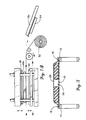
- FIG. 1 and FIG. 1B which, taken together, schematically illustrate the automatic apparatus and steps for practicing the invention in the environment of a continuous "in-line” manufacturing process for encapsulating a pre-formed article within an envelope, or in this instance, opposed sheets, of plastic film.
- FIG. 1 and FIG. 1B schematically illustrate the automatic apparatus and steps for practicing the invention in the environment of a continuous "in-line” manufacturing process for encapsulating a pre-formed article within an envelope, or in this instance, opposed sheets, of plastic film.
- FIG. 1 and FIG. 1B which, taken together, schematically illustrate the automatic apparatus and steps for practicing the invention in the environment of a continuous "in-line” manufacturing process for encapsulating a pre-formed article within an envelope, or in this instance, opposed sheets, of plastic film.
- the individual pre-formed articles 10, which in this instance are pre-molded fiber glass hoodliners, are disposed above a generally continuously running horizontal endless belt 12 in a vertical stack.
- a web of plastic film 15, such as polyethylene film is fed from a first supply roll 14 onto the belt 12 at the upstream end thereof as at 16.
- the belt 12 in fact, comprises two transversely spaced horizontal chains, spaced so as to engage the plastic film 15 adjacent the opposed edges.
- each chain includes teeth 18 projecting therabove so that, as the plastic film 15 is fed onto the belt 12, a pressure roll 20 presses each marginal edge of the film against the teeth to perforate the film and cause the film to be positively driven by the chain teeth 18.
- each side chain 12 is synchronously driven so that both sides of the plastic film are moved in coordination with one another.
- An indexing or aligning mechanism 22 is positioned over the film 15 and movably disposed so as to, in one position, contact some portion of the article 10 to appropriately position the article on the film. in a predetermined relationship.
- a plurality of heat-staking heads 24 are reciprocally mounted subjacent the film in alignment with some portion of the article 10 supported thereon. The staking heads 24 are actuated once the article has been properly aligned on the film 15.
- the heated heads 24 are elevated to contact the underface of the film 15, pressing it into contact with an opposed portion of the underface of the article 10, thereby heat-staking the article 10 onto the film 15 so that thereafter the article 10 and the film 15 travel as a unit.
- the drive chain 12 is again actuated to advance the article 10 and film 15 to a station where an upper or top web of film 26 is supplied to cover the upper face of the article 10.
- the margins or edges of the upper film are pressed and perforated by the teeth 18 on the chain 12 through another pressure roller 28 so that movement of the chain 12 causes the upper feed roll 30 to continue to feed plastic film 26.
- FIG. 3 wherein the teeth 18 carried by the chains 12 are shown after having pierced the edge portions of the upper and lower webs of plastic film.
- the article 10, as sandwiched between the upper 26 and lower 15 layers of film, is driven, through the drive of the film, to the next station where opposed upper 32 and lower 34 heaters preheat the film above and below the article 10 for a predetermined period of time.
- These heaters 32, 34 can be any appropriate heaters although radiant heaters are preferred.
- From the preheat station the article 10 as sandwiched between the film is progressively driven to the next station which comprises the main heater 36 and evacuation device 38.
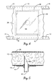
- FIG. 4 The location of the article 10 and the edge portions of the upper and lower webs of film with respect to the lower frame member 46 is illustrated more clearly in FIG. 4. Since the frame members 44 and 46 are vertically aligned, it will be understood that the upper frame member 44 is similarly transversely spaced from the article 10 and the edge portions of the webs. Also, a plurality of vertically projecting vacuum needles 40 are reciprocally mounted below the lower film 15 and are attached to a vacuum header 42.
- the vacuum needles 40 are elevated to a position where they pierce the lower film 15 and project upwardly a predetermined distance to an intermediate position within the article 10 so that, upon the film and 26 being heated to its softening or fusion temperature, the air within the volume occupied by the article between the opposed upper and lower films is evacuated, causing upper 26 and lower 15 films to be fused either to the article 10 or, in those areas where there is no article, to each other.
- the article 10, as encapsulated within the plastic film 15 and 26, is moved to the final station wherein the plastic film is trimmed from the article so that the final encapsulated article 10a, encased on all exposed surfaces within a plastic film, is freed from the excess film.
- reciprocal trim presses 48 and 50 are disposed on opposite sides of the article 10a with the presses having the exact outer dimensions and configuration as the article for trimming any flange or pinched edge portions of the film and for also trimming the plastic film from any interior openings within the article. It is to be understood that it is necessary to exactly dispose the article relative to the knife edges 48a of the reciprocal trim presses 48 and 50.
- the article 10a will be contacted by the knife edges and damaged thereby.
- the initial indexing of the article 10 on the lower film 15 as described in the first station be coordinated with the proper positioning of the article 10a in the trim presses 48 and 50.
- the reciprocal trim presses completing their trimming operation, they are separated to permit the continued movement of the edge strips of the films 15 and 26 and the portions of the opposed film 15 and 26 remaining after the trimming operation has severed the article 10a from the web.
- edge strips and remaining web portions are fed to a take-up roll 52 which, due to the engagement of the remaining web portions with the article 10a, moves the article 10a out of the presses 48 and 50 and onto a discharge chute 54 wherein the encased or encapsulated molded article 10a can be removed.
- each frame member 44, 46 defines an outer frame of the same configuration, such as to completely surround and enclose the outer margins of the article 10.
- the opposed facing surfaces 44a, 46a are generally flat for engaging the respective surface of film and, when in final position, pinch the opposed film between these opposed surfaces to thereby define, within the confines of the frames 44, 46, a substantially airtight enclosure that includes therein the article as sandwiched between the upper and lower films 26, 15.
- the reciprocal vacuum probes or needles 40 also define adjacent their open end 40a, a platform 41 adjustably mounted thereon, such as a washer frictionally or threadably engaging the needle, which limits the depth of penetration of the needle through the lower film 15 and into the article 10 so that the final disposition of each needle is within the vertical thickness of the article 10.
- the platform on each needle is individually adjusted depending upon the thickness of the article at the position of penetration so that each needle 40 is thereby prevented from extending through the article 10.
- the washers 41 are adjustable on the needles, any thickness of article can be accommodated and the depth of penetration controlled to be disposed in an appropriate location within the article 10.
- the platforms provide support for the article, especially necessary during heating of the lower plastic film.
- the article 10 must be sufficiently permeable so that the volume defined between the opposed webs 15, 26 of film and as bounded by the opposed frame members can be evacuated by flow of air through the article 10. Further, the penetration of the needles through the lower film and article maintains the proper registry of the article on the lower film and prevents any relative movement therebetween that might occur upon softening of the fused heat-staking attachment.
- the heat causes the air within the volume formed by the frames 44, 46 and the opposed plastic films 15 and 26 to expand so that, upon the plastic film obtaining its flow or softening temperature, the films 15 and 26 tend to drum up.
- the evacuation step is initiated to immediately draw the opposed films into intimate contact with the article 10 and fuse to either the marginal edges and the top and bottom surfaces thereof or fuse to the opposite film in those areas where the film is not separated by the article, such as completely around the marginal edge and within any openings formed in the article 10.
- the finished encapsulated article 10a is shown in FIG. 6. It has been found that encapsulation of an article 10 by the method described, even when such article has non-planar, contoured or abruptly discontinuous surfaces, forces the film into direct, intimate contact with all surfaces, thereby exactly duplicating the original article shape and configuration, without bridging (i.e., extending from one surface to an adjacent but displaced surface without engaging the contoured or sharp-angle surface joining such two displaced surfaces).
- bridging i.e., extending from one surface to an adjacent but displaced surface without engaging the contoured or sharp-angle surface joining such two displaced surfaces.
- the true exterior contour of the article 10 as molded or otherwise shaped is reproduced in the item as encased hereby.
- all marginal edges of the article are covered by a layer of film, and the trimming can occur substantially immediately adjacent such marginal edges to eliminate any double-layer plastic flange or seam. Edges of interior openings such as at 56 formed in the article are also covered with the film.
- the method and apparatus of this invention are specifically suited for automatically, in an in-line continuous process, encapsulating pre-formed, porous, permeable articles so that the air evacuating probe or need!es can be positioned within the article, and the air within the envelope containing the article (as defined by the opposed plastic films) can be evacuated from all sides and faces of the article by flowing through the article and into the probe.
- the process further supports the article without the necessity of nesting in a mold or the like.
- the method and apparatus of the present invention are particularly suited for use with a fibrous or porous article that permits relatively easy air flow therethrough and also must have some initial rigidity to prevent, under the evacuation of the air therefrom, distortion or compression of its initial configuration.
- a pre-molded fiber glass article such as a hoodliner as previously mentioned.
Abstract
A method and apparatus for encapsulating a porous article (10) in plastic film without employing supporting molds. The article is deposited onto a lower web (15) and an upper web (26) is moved into overlying position. The edges of the webs are gripped by moving teeth (18) to move the webs and the article in unison. The webs are then pinched together adjacent the article to form an enclosed volume. The film is heated to its fusing temperature and the enclosed volume is evacuated through a tube (40) inserted through the lower web (15) and into the article (10). The tube is removed and the fused webs are trimmed adjacent the edges of the article, resulting in an encapsulated article (10a).
Description
- This invention relates to a method of encapsulating an article in a plastic film. More particularly, it relates to apparatus and the method of encapsulating a contoured article, such as a pre-molded highly porous fiber glass article, in a thin plastic film on all surfaces by means of heating and vacuum-forming the film to the contoured article. This invention relates generally to the invention described in co-pending U.S. Patent Application Serial No. 224,639 filed July 27, 1988, both being assigned to a common assignee.
- Vacuum forming is typically used for forming thick (50-120 mils) heat-deformable articles such as plastic refrigerator door liners. Additionally, vacuum forming is a common method of encapsulating one or more articles within a plastic film material, usually for the purpose of shipping the articles as a package. Techniques for wrapping articles by this method are well known and are distinct from heat-shrink wrapping of articles. In a vacuum forming operation plastic film material, having a thickness in the range of 10-100 miles, is softened by heat and formed to the desired shape by vacuum, whereas in shrink wrapping the film is heated to cause it to shrink about an article. Although the plastic material used in a vacuum forming operation may shrink slightly during the process, perhaps in the order of a few percent of its original size, it is insignificant compared to the shrinkage of film in a shrink wrap operation where the film may readily shrink 75% in the main direction and 30% in the cross direction.
- There are reasons other than for ease of handling for wrapping articles with plastic film, one being to prevent fibrous articles from releasing fibers to the environment. An example is in the manufacture of automobile hoodliners formed of fiber glass. Such hoodliners are shaped by molding and trimming a bonded fiber glass mat to the contour of an automobile hood. Workers in the assembly line who are located beneath installed hoodliners are at times exposed to fibers broken and released from such fiber glass hoodliners, particularly if the hoodliners are subjected to vibration or shock. As a way of eliminating this, it has been suggested to encapsulate the fiber glass hoodliners in a thin film. The contoured shape of hoodliners, however, raises problems.
- To encase a hoodliner in a plastic film by the shrink-wrap method would be too expensive due to the type of plastic film required compared to the plastic material used in vacuum forming operations and, in encasing contoured articles, utilization of the shrink-wrap material and method causes the film, quite often, to bridge the contoured surfaces of the encased article and not conform exactly to the surface as is required for maintaining the desired shape of the hoodliner.
- To overcome the bridging tendency, a vacuum forming process could be used wherein the plastic film would be supported on a frame and heated to its softening temperature and then lowered into contact with an upper face of a contoured article. Holes in the mold would permit a vacuum to be applied, through the opposite side of the permeable contoured article, or the uncoated side, to draw a vacuum in the volume between the mold and the plastic film, drawing the film down onto the top surface of the article and conforming it to the exact contour thereof. This process would be effective to coat one face of the article; however, to coat the other face would require inverting the article in another mold, supporting it with a contoured surface conforming to that surface and again. heating a film of plastic and applying it to the then top surface. However, to evacuate the volume between the last applied film and the mold would require piercing the previously applied film to be able to apply an appropriate vacuum to draw the film onto the article. As is evident, such a process requires a multiple step operation utilizing contoured molds and further requires the use of a relatively tough film capable of withstanding the stresses to which it is subjected during such handling and encapsulating process. Further, such method would typically leave the marginal edges of the hoodliner uncoated, thereby yielding an article that still exposed workers, through subsequent handling, to edge fibers from the hoodliner.
- The aforementioned commonly assigned patent application discloses a method of encapsulating a molded fiber glass hoodliner using heat and vacuum to conform the plastic film onto the hoodliner; however, such method is not amenable to automated in-line production techniques and still requires undesirable manual operations.
- The present invention provides a method and apparatus for encapsulating a contoured permeable article in a film of heat formable material in a continuous in-line automated process which includes the major steps of 1) positioning the article between two generally horizontally oriented continuous webs of plastic film, 2) attaching the article to at least one of the webs so they are moved as a unit thereafter, 3) securing the opposed webs into contact with each other around the entire outer periphery of the article to define a generally enclosed volume between the webs containing the article, 4) evacuating the air from within the enclosed volume, including the interior of the porous article while, or just subsequent to, 5) heating the plastic film forming the enclosed volume to its flow temperature, causing the plastic film to conform exactly to the contour of the article and, in areas of direct contact between the opposed plastic films, such as along the periphery of the article and within any internal opening through the article, fusing the opposed plastic films together. The, evacuation preferably is carried out by piercing the bottom web of plastic film with hollow evacuating needles that project into and terminate within the permeable article. Thereafter the needles are withdrawn from the encapsulated article and the excess plastic film is trimmed from the fused marginal edges of the contoured article, including removal from any internal openings in the article.
- In addition to the in-line encapsulation process, a main feature of the invention is to encapsulate a porous, contoured article in a film without the use of a supporting mold. The article is primarily supported instead by the lowermost web or sheet of plastic film between the pinched portions thereof during the evacuation of the enclosed volume and the fusing of the plastic film through the application of heat. This ability speeds the encapsulating process and considerably reduces its cost. However, during the heating step, the softening of the plastic requires additional support be provided. Such secondary support is provided by adjustable platforms secured to the evacuating needles.
- Within the in-line process of encapsulation, the present invention further includes controlling the depth of penetration of the evacuation needles into the article. Again, an adjustable platform on each needle limits the needle penetration, and thereafter supports the article during the heating and evacuation steps.
- The apparatus for accomplishing the above in-line steps includes movable frame members moveable into face-to-face engagement for forcing the top and bottom plastic films together in a horizontal position once the article has been disposed therebetween, and a vacuum manifold movably supporting a plurality of vertically projecting hollow evacuating needles, in fluid communication with the vacuum manifold. A platform or planar support means is adjustably positioned on each needle, generally subjacent the terminal piercing end thereof, which determines the depth of penetration of the needles into the molded article as the manifold is moved upwardly, forcing the needles to penetrate into the permeable article. The support means are predisposed such that the needles pierce the lower plastic film and project into strategically located areas of the permeable article without piercing the opposed upper plastic sheet and to provide support to the article during the heating cycle.
- A heating chamber, having heating means, heats the plastic film to the flow temperature (which can be determined by observing the plastic film drumming-up because of the expansion of air within the enclosed volume, or which can be automatically timed or otherwise sensed) whereupon the volume between the opposed films is evacuated of air through the needles, causing the plastic films to intimately bond to either the molded article or to fuse together in those areas not separated by the article. A trimming press trims the excess plastic film from around all marginal edges, thereby yielding an encapsulated article.
- Preferably, the contoured permeable article for this encapsulation process is formed of a fiber glass sheet; however, other permeable objects could also be encapsulated in accordance with this invention.
-
- FIG. 1 is a schematic drawing illustrating the present invention, both process and apparatus, in a continuous "in-line" arrangement;
- FIG. 1B is a schematic elevational view similar to FIG. 1 showing the final operation in the "in-line" practice of the invention;
- FIG. 2 is a schematic elevational view of an intermediate operation shown in FIG. 1 but further illustrating the heating and evacuation apparatus and steps of the present invention;
- FIG. 3 is a transverse cross-sectional view taken along line 3-3 of FIG. 1;
- FIG. 4 is a plan view of the apparatus at the heating and evacuation station, taken along line 4-4 of FIG. 1, showing the relationship of the article and webs to the clamping frame;
- FIG. 5 is an enlarged cross-sectional view showing an evacuation needle disposed within the article; and
- FIG. 6 is an isometric view of a finished encapsulated, molded article, to illustrate typical contours and openings of such an article.
- Reference will be made to FIG. 1 and FIG. 1B which, taken together, schematically illustrate the automatic apparatus and steps for practicing the invention in the environment of a continuous "in-line" manufacturing process for encapsulating a pre-formed article within an envelope, or in this instance, opposed sheets, of plastic film. However, it is to be understood that although the description refers to the automatic operation of the "in-line" process, each separate operation within such process could be accomplished at separate stations that are not "in-line" and with the transfer of the article to each station being done manually as opposed to the continuous feeding along an endless path as disclosed in FIG. 1 and FIG. 1B herein. Thus, as shown by the above identified Figures, the individual pre-formed
articles 10, which in this instance are pre-molded fiber glass hoodliners, are disposed above a generally continuously running horizontalendless belt 12 in a vertical stack. A web ofplastic film 15, such as polyethylene film, is fed from afirst supply roll 14 onto thebelt 12 at the upstream end thereof as at 16. In this instance, thebelt 12, in fact, comprises two transversely spaced horizontal chains, spaced so as to engage theplastic film 15 adjacent the opposed edges. Thus, each chain includesteeth 18 projecting therabove so that, as theplastic film 15 is fed onto thebelt 12, apressure roll 20 presses each marginal edge of the film against the teeth to perforate the film and cause the film to be positively driven by thechain teeth 18. It is to be understood that eachside chain 12 is synchronously driven so that both sides of the plastic film are moved in coordination with one another. - As the
film 15 passes under the vertical stack ofarticles 10 it is temporarily stopped to permit the lowermost article in the stack to be dropped onto the plastic film in an area generally unsupported by any structure underneath thefilm 15. An indexing or aligningmechanism 22 is positioned over thefilm 15 and movably disposed so as to, in one position, contact some portion of thearticle 10 to appropriately position the article on the film. in a predetermined relationship. A plurality of heat-stakingheads 24 are reciprocally mounted subjacent the film in alignment with some portion of thearticle 10 supported thereon. The staking heads 24 are actuated once the article has been properly aligned on thefilm 15. Once actuated, theheated heads 24 are elevated to contact the underface of thefilm 15, pressing it into contact with an opposed portion of the underface of thearticle 10, thereby heat-staking thearticle 10 onto thefilm 15 so that thereafter thearticle 10 and thefilm 15 travel as a unit. - After heat-staking the
article 10 to the lower web offilm 15, thedrive chain 12 is again actuated to advance thearticle 10 andfilm 15 to a station where an upper or top web offilm 26 is supplied to cover the upper face of thearticle 10. As before, the margins or edges of the upper film are pressed and perforated by theteeth 18 on thechain 12 through another pressure roller 28 so that movement of thechain 12 causes the upper feed roll 30 to continue to feedplastic film 26. This arrangement can be seen more clearly in FIG. 3, wherein theteeth 18 carried by thechains 12 are shown after having pierced the edge portions of the upper and lower webs of plastic film. - The
article 10, as sandwiched between the upper 26 and lower 15 layers of film, is driven, through the drive of the film, to the next station where opposed upper 32 and lower 34 heaters preheat the film above and below thearticle 10 for a predetermined period of time. Theseheaters article 10 as sandwiched between the film is progressively driven to the next station which comprises the main heater 36 and evacuation device 38. In this heating and evacuating station, again there are opposed upper 36a and lower 36b heaters which are actuated when thearticle 10 arrives at a predetermined position therebetween along with opposed verticallymovable frame members article 10, which are moved toward each other to pinch the plastic films together about the perimeter of the article. - The location of the
article 10 and the edge portions of the upper and lower webs of film with respect to thelower frame member 46 is illustrated more clearly in FIG. 4. Since theframe members upper frame member 44 is similarly transversely spaced from thearticle 10 and the edge portions of the webs. Also, a plurality of vertically projecting vacuum needles 40 are reciprocally mounted below thelower film 15 and are attached to avacuum header 42. The vacuum needles 40 are elevated to a position where they pierce thelower film 15 and project upwardly a predetermined distance to an intermediate position within thearticle 10 so that, upon the film and 26 being heated to its softening or fusion temperature, the air within the volume occupied by the article between the opposed upper and lower films is evacuated, causing upper 26 and lower 15 films to be fused either to thearticle 10 or, in those areas where there is no article, to each other. - From the above identified heating and evacuating station, and with reference particularly to FIG. 1B, the
article 10, as encapsulated within theplastic film article 10a, encased on all exposed surfaces within a plastic film, is freed from the excess film. To this end, reciprocal trim presses 48 and 50 are disposed on opposite sides of thearticle 10a with the presses having the exact outer dimensions and configuration as the article for trimming any flange or pinched edge portions of the film and for also trimming the plastic film from any interior openings within the article. It is to be understood that it is necessary to exactly dispose the article relative to the knife edges 48a of the reciprocal trim presses 48 and 50. Otherwise, thearticle 10a will be contacted by the knife edges and damaged thereby. Thus, it is important that the initial indexing of thearticle 10 on thelower film 15 as described in the first station be coordinated with the proper positioning of thearticle 10a in the trim presses 48 and 50. Upon the reciprocal trim presses completing their trimming operation, they are separated to permit the continued movement of the edge strips of thefilms film article 10a from the web. The edge strips and remaining web portions are fed to a take-up roll 52 which, due to the engagement of the remaining web portions with thearticle 10a, moves thearticle 10a out of thepresses discharge chute 54 wherein the encased or encapsulated moldedarticle 10a can be removed. - Referring now to FIG. 2, the heating and evacuation apparatus and procedure is more clearly shown and explained. As therein seen, the
article 10, as sandwiched between the upper 26 and lower 15 plastic film, is properly positioned within the station, and thelower frame member 46 is elevated from below the lower film to a position wherein anupper face 46a of theframe member 46 is in contact with the lower face of thelower film 15. Also, an upperreciprocal frame member 44 is likewise lowered to a position where a downwardly facingface 44a contacts the upper face of theupper film 26. It is to be understood that eachframe member article 10. The opposed facingsurfaces frames lower films - With reference to FIG. 5, it is seen that the reciprocal vacuum probes or
needles 40 also define adjacent theiropen end 40a, aplatform 41 adjustably mounted thereon, such as a washer frictionally or threadably engaging the needle, which limits the depth of penetration of the needle through thelower film 15 and into thearticle 10 so that the final disposition of each needle is within the vertical thickness of thearticle 10. The platform on each needle is individually adjusted depending upon the thickness of the article at the position of penetration so that eachneedle 40 is thereby prevented from extending through thearticle 10. As thewashers 41 are adjustable on the needles, any thickness of article can be accommodated and the depth of penetration controlled to be disposed in an appropriate location within thearticle 10. - Once the needles are elevated to their final, penetrating position, the platforms provide support for the article, especially necessary during heating of the lower plastic film. It is again pointed out that the
article 10 must be sufficiently permeable so that the volume defined between theopposed webs article 10. Further, the penetration of the needles through the lower film and article maintains the proper registry of the article on the lower film and prevents any relative movement therebetween that might occur upon softening of the fused heat-staking attachment. - Further, it is to be understood that during the fusion heating, the heat causes the air within the volume formed by the
frames plastic films films article 10 and fuse to either the marginal edges and the top and bottom surfaces thereof or fuse to the opposite film in those areas where the film is not separated by the article, such as completely around the marginal edge and within any openings formed in thearticle 10. - The finished encapsulated
article 10a is shown in FIG. 6. It has been found that encapsulation of anarticle 10 by the method described, even when such article has non-planar, contoured or abruptly discontinuous surfaces, forces the film into direct, intimate contact with all surfaces, thereby exactly duplicating the original article shape and configuration, without bridging (i.e., extending from one surface to an adjacent but displaced surface without engaging the contoured or sharp-angle surface joining such two displaced surfaces). Thus the true exterior contour of thearticle 10 as molded or otherwise shaped is reproduced in the item as encased hereby. Also, all marginal edges of the article are covered by a layer of film, and the trimming can occur substantially immediately adjacent such marginal edges to eliminate any double-layer plastic flange or seam. Edges of interior openings such as at 56 formed in the article are also covered with the film. - As previously stated, the method and apparatus of this invention are specifically suited for automatically, in an in-line continuous process, encapsulating pre-formed, porous, permeable articles so that the air evacuating probe or need!es can be positioned within the article, and the air within the envelope containing the article (as defined by the opposed plastic films) can be evacuated from all sides and faces of the article by flowing through the article and into the probe. The process further supports the article without the necessity of nesting in a mold or the like.
- It is acknowledged that in the finished form one face of the encapsulated article has small puncture openings which during the process were occupied by the probes projecting therethrough. However, such openings are generally not apparent and are acceptable in the finished article as none of the fibrous material forming the article, or dust within the article, is able to be expelled from or exit such openings. Also, such openings are normally placed on a surface that is not viewed when the article is assembled in its final position, or can be subsequently covered by another aesthetically attractive outer layer. Thus it is seen that the method and apparatus of the present invention are particularly suited for use with a fibrous or porous article that permits relatively easy air flow therethrough and also must have some initial rigidity to prevent, under the evacuation of the air therefrom, distortion or compression of its initial configuration. Such system is particularly well suited to a pre-molded fiber glass article such as a hoodliner as previously mentioned. Although polyethylene film has been given as one example of plastic film which may be used in the invention, it will be obvious that other plastic films can be utilized as well.
Claims (30)
1. A continuous method of encapsulating a contoured generally porous article within a plastic film, comprising the steps of:
moving a lower web of plastic film in a downstream direction;
causing the article to engage the lower web and to be moved therewith;
covering the article with an upper web of plastic film and moving the upper and lower webs as a unit;
forcing the upper and lower webs together generally adjacent the periphery of the article to form an enclosed volume therebetween containing the article;
heating the upper and lower webs of plastic film in the area associated with the article to a predetermined fusing temperature at which the films are capable of adhering to said article and to each other;
evacuating air from the enclosed volume to cause the upper and lower webs to engage and conform to the shape of the adjacent surfaces of the article and to engage each other in areas unobstructed by the article, the heated films thereby adhering to the engaged surfaces of the article and fusing together in the engaged areas of the upper and lower webs; and
trimming the fused webs of film adjacent the eyes of the article.
2. The method of claim 1, wherein the moving webs are intermittently moved, the movement of the webs being halted during the evacuation and trimming steps.
3. The method of claim 1, wherein the lower web is moved by gripping the edge portions thereof and moving the gripped edge portions in said downstream direction.
4. The method of claim 3, wherein the upper and lower webs are moved as a unit by engaging the edge portions of the upper web with the edge portions of the lower web and causing the gripping and movement of the edge portions of the lower web to also grip and move the edge portions of the upper web.
5. The method of claim 1, wherein causing the article to engage the lower web includes the step of depositing the article onto the lower web and securing the article thereto.
6. The method of claim 5, wherein the article is secured to the lower web by heating predetermined portions of the lower web, which are in contact with the article, to the fusing temperature of the plastic film to cause the article to adhere to the lower web at said portions.
7. The method of claim 5, wherein the lower web is generally unsupported between the edge portions thereof and the article is transported by the unsupported portions of the lower web; and wherein said heating step includes supporting the article at spaced individual locations with individual support members.
8. The method of claim 1, wherein air is evacuated from the enclosed volume containing the article by inserting a relatively narrow tube through one of the webs and into the body of the porous article so as to be disposed within said article, and applying a vacuum to the tube, said disposition of said tube being limited by platform means secured to said tube.
9. The method of claim 8, wherein the tube is removed from the article prior to the step of trimming the fused webs of film.
10. Apparatus for continuously encapsulating a contoured generally porous article within a plastic film, comprising:
means for moving a lower web of plastic film in a downstream direction;
means for causing the article to engage the lower web and to move therewith;
means for covering the article with an upper web of plastic film and moving the upper and lower webs as a unit;
means for forcing portions of the upper and lower webs together generally adjacent the periphery of the article to form an enclosed volume containing the article;
means for heating the upper and lower webs of plastic film to a predetermined fusing temperature at which the films are capable of adhering to said article and to each other;
means for evacuating air from the enclosed volume to cause the upper and lower webs to engage and conform to the shape of the adjacent surfaces of the article and to engage each other in areas unobstructed by the article, the heated films thereby adhering to the engaged surfaces of the article and fusing together in the engaged areas of the upper and lower webs;
adjustably positioned means for supporting said article during at multiple spaced individual locations during the heating of said films; and
means for trimming the fused webs of film adjacent the edges of the article.
11. The apparatus of claim 10, wherein the means for moving the lower web comprises means for gripping the edge portions thereof and moving the gripped edge portions in said downstream direction.
12. The apparatus of claim 11, wherein the means for gripping the edge portions of the lower web comprises teeth for piercing the edge portions of the lower web and means for moving the teeth in a downstream direction.
13. The apparatus of claim 12, wherein the means for moving the teeth comprise endless chains to which the teeth are attached.
14. The apparatus of claim 13, wherein the means for moving the upper and lower webs as a unit comprises means for feeding the edge portions of the upper web into contact with the teeth, whereby the teeth pierce said edge portions of the upper web in addition to the edge portions of the lower web to move both webs together in said downstream direction.
15. The apparatus of claim 10, wherein the means for causing the article to engage the lower web comprises means for periodically depositing an article onto the lower web, and wherein the means for attaching the article to the lower web comprises means for heating spaced locations on the lower web which are in contact with the article to the fusing temperature of the plastic film to cause the plastic film of the lower web to adhere to the article at said spaced locations.
16. The apparatus of claim 10, wherein the lower web is generally unsupported between the edge portions thereof, the article being carried by the unsupported portions of the lower web.
17. The apparatus of claim 10, wherein the means for evacuating air from the enclosed volume containing the article comprises means for inserting a relatively narrow tube through one of the webs and into the body of the porous article, and means for applying a vacuum to the tube.
18. The apparatus of claim 17, including means for preventing penetration of the tube into the body of the article beyond a predetermined distance.
19. The apparatus of claim 18, wherein the means for preventing penetration of the tube beyond a predetermined distance also provide said means for supporting said article during the heating and comprises an adjustable platform connected to the tube at said predetermined distance from the end of the tube, so that when the platform contacts the bottom face of the article the tube is prevented from further penetration into the article and supports the article.
20. The apparatus of claim 10, including means for winding up the remaining portions of the web after the trimming operation.
21. A method of encapsulating a contoured, genially porous article in a plastic film without the use of a supporting mold, comprising the steps of:
disposing said article between opposed sheets of plastic film, one of said sheets being in a generally lowermost position and the other sheet being in a generally uppermost position relative to each other;
placing said sheets in engagement generally adjacent the periphery of said article to form an enclosed volume containing said article, at least substantial portions of the lowermost sheet between the engaged portions thereof supporting the article;
heating said sheets to a predetermined fusing temperature capable of causing facing portions of said sheets to adhere to the article or to one another;
during heating supporting said article at multiple individual spaced locations of said article;
evacuating the enclosed volume and the interior of said porous article, thereby causing said plastic sheets to intimately engage the surfaces of said article and assume the same contour as the article;
lowering the temperature of the plastic sheets below their predetermined fusing temperature; and
trimming the fused sheets adjacent the periphery and adjacent any other edges of the article.
22. The method of claim 21, wherein the lowermost sheet between the engaged portions thereof supports substantially the entire weight of the article during all steps except the heating step.
23. The method of claim 21, wherein the enclosed volume and the interior of the porous article are evacuated by inserting a tube into said article for air flow communication exteriorly of the enclosed volume and applying a vacuum to the tube.
24. The method of claim 23, wherein the tube is inserted through one of the plastic sheets, and wherein the tube is removed from the article and the enclosure prior to trimming the fused sheets.
25. Apparatus for encapsulating a contoured, generally porous article in a plastic film without the use of a supporting mold, comprising:
means for maintaining said article between opposed sheets of plastic film, one of said sheets being in a generally lowermost position and the other sheet being in a generally uppermost position relative to each other;
means for forcing said sheets together generally adjacent the periphery of said article to form an enclosed volume containing said article, at least substantial portions of the lowermost sheet within said periphery supporting the article;
means for heating said sheets to a predetermined fusing temperature capable of causing engaging facing portions of said sheets to adhere to the article or to one another;
means for supporting said article, at multiple spaced individual locations while said article and plastic sheets are being heated;
means for evacuating the enclosed volume and the interior of said porous article, thereby causing said plastic sheets to intimately engage the surfaces of said article and assume the same contour as the article;
means for forcing the temperature of the plastic sheets below their predetermined fusing temperature; and
means for trimming the fused sheets adjacent the periphery and adjacent any other edges of the article.
26. The apparatus of claim 25, wherein the lowermost sheet between the pinched portions thereof supports substantially the entire weight of the article except during heating of said article and said sheets.
27. The apparatus of claim 25, wherein the means for evacuating the enclosed volume and the interior of the porous article comprises means for inserting a tube into said article for air flow communication exteriorly of the enclosed volume and applying a vacuum to the tube.
28. The apparatus of claim 27, including means for removing the tube from the article and the enclosure prior to the trimming of the fused sheets.
29. The apparatus of claim 27, including means for automatically limiting the distance that the tube is inserted into the article said means further comprising said support means during said heating of said article and plastic sheets.
30. The apparatus of claim 25, wherein the means for lowering the temperature of the plastic sheets comprises means for moving the article and enclosing plastic sheets away from the means for heating the plastic sheets.
Applications Claiming Priority (2)
| Application Number | Priority Date | Filing Date | Title |
|---|---|---|---|
| US419227 | 1989-10-10 | ||
| US07/419,227 US5098498A (en) | 1989-10-10 | 1989-10-10 | Apparatus and method for encapsulating contoured articles |
Publications (2)
| Publication Number | Publication Date |
|---|---|
| EP0422542A2 true EP0422542A2 (en) | 1991-04-17 |
| EP0422542A3 EP0422542A3 (en) | 1992-01-02 |
Family
ID=23661346
Family Applications (1)
| Application Number | Title | Priority Date | Filing Date |
|---|---|---|---|
| EP19900119229 Withdrawn EP0422542A3 (en) | 1989-10-10 | 1990-10-06 | Apparatus and method for encapsulating contoured articles |
Country Status (6)
| Country | Link |
|---|---|
| US (1) | US5098498A (en) |
| EP (1) | EP0422542A3 (en) |
| JP (1) | JPH03226432A (en) |
| CA (1) | CA2027166A1 (en) |
| IE (1) | IE903612A1 (en) |
| MX (1) | MX167081B (en) |
Cited By (7)
| Publication number | Priority date | Publication date | Assignee | Title |
|---|---|---|---|---|
| WO1993020998A1 (en) * | 1992-04-16 | 1993-10-28 | Ab Åkerlund & Rausing | A container lid and its method of production |
| EP1396432A2 (en) * | 2002-09-06 | 2004-03-10 | HAGMANN Maschinenbau AG | Heat-sealing machine for packaging products, such as food |
| WO2005099997A1 (en) * | 2004-04-16 | 2005-10-27 | France (Qld) Pty Ltd | Vacuum form encapsulated articles |
| US7544262B2 (en) | 2002-06-11 | 2009-06-09 | Airdex International, Inc. | Method of making a dunnage platform |
| US7689481B2 (en) | 2006-02-15 | 2010-03-30 | Airdex International, Inc. | Light weight, strong, fire retardant dunnage platform bag and system of loading, dispensing and using bag |
| US7963397B2 (en) | 2006-02-09 | 2011-06-21 | Seagle Vance L | Modular, knock-down, light weight, thermally insulating, tamper proof shipping container and fire retardant shipping container bag |
| US10287054B2 (en) | 2014-06-25 | 2019-05-14 | Airdex Corporation | Load bearing structure |
Families Citing this family (19)
| Publication number | Priority date | Publication date | Assignee | Title |
|---|---|---|---|---|
| US5142842A (en) * | 1989-12-13 | 1992-09-01 | W. R. Grace & Co.-Conn. | Method for making a film/foil panel |
| JPH0745182B2 (en) * | 1990-06-29 | 1995-05-17 | 株式会社ゲット | Method for manufacturing pipe lining material |
| GB9017279D0 (en) * | 1990-08-07 | 1990-09-19 | Micropore International Ltd | Method for making a body of particulate insulating material |
| DE4206262A1 (en) * | 1992-02-28 | 1993-09-02 | Kiefel Hochfrequenz Paul | METHOD FOR WELDING HALOGEN-FREE THERMOPLASTIC FILMS |
| US5277743A (en) * | 1992-03-17 | 1994-01-11 | Copeland Nancy S | Panel sealing system |
| US5848509A (en) * | 1995-08-31 | 1998-12-15 | Certainteed Corporation | Encapsulated insulation assembly |
| US5685938A (en) * | 1995-08-31 | 1997-11-11 | Certainteed Corporation | Process for encapsulating glass fiber insulation |
| US5800657A (en) * | 1995-10-18 | 1998-09-01 | The Standard Products Company | Method of intermittent length stabilization |
| US5989473A (en) * | 1996-07-29 | 1999-11-23 | David G. Haverty | Manufacturing composite parts with integral porous components |
| DE60042226D1 (en) * | 1999-06-08 | 2009-07-02 | Kaneka Corp | A method of encapsulating a photovoltaic module by means of an encapsulating material |
| US6492012B1 (en) * | 2000-02-02 | 2002-12-10 | Tilak M. Shah | Polymer penetrated porous substrates |
| AU1349702A (en) * | 2000-10-26 | 2002-05-06 | James Hardie Res Pty Ltd | Building panel assembly having a protective film, method of making same and adhesive system for bonding the protective film |
| DE10056461C1 (en) * | 2000-11-14 | 2002-06-06 | Msk Verpackung Syst Gmbh | Method and device for multi-sided wrapping of irregularly shaped objects |
| JP4754123B2 (en) * | 2001-09-10 | 2011-08-24 | 大森機械工業株式会社 | PTP packaging machine and packaging method |
| US20030131935A1 (en) * | 2002-01-15 | 2003-07-17 | Dyne Dave Van | Apparatus and method for bonding facing to insulation |
| US20030159778A1 (en) * | 2002-02-27 | 2003-08-28 | Kunihiko Koroyasu | Plasma processing apparatus, protecting layer therefor and installation of protecting layer |
| US8281535B2 (en) | 2002-07-16 | 2012-10-09 | James Hardie Technology Limited | Packaging prefinished fiber cement articles |
| WO2004007193A2 (en) | 2002-07-16 | 2004-01-22 | James Hardie International Finance B.V. | Packaging prefinished fiber cement products |
| JP3979301B2 (en) * | 2003-02-19 | 2007-09-19 | 株式会社デンソー | Insert molding method |
Citations (7)
| Publication number | Priority date | Publication date | Assignee | Title |
|---|---|---|---|---|
| FR970835A (en) * | 1948-03-30 | 1951-01-09 | Wingfoot Corp | Packing process |
| FR2004752A1 (en) * | 1968-03-26 | 1969-11-28 | Uddeholms Ab | |
| US4044524A (en) * | 1974-11-12 | 1977-08-30 | Luigi Segale | Method of packaging products to be preserved under vacuum or atmosphere of suitable gases |
| WO1982000623A1 (en) * | 1980-08-12 | 1982-03-04 | A Stumsner | A package containing a liquid-impregnated sponge and a method and a machine for manufacturing said package |
| FR2540460A1 (en) * | 1983-02-09 | 1984-08-10 | Grace Sarl | Method and apparatus for automatically packaging at least one object in separate individual packages |
| EP0339275A2 (en) * | 1988-03-25 | 1989-11-02 | Somar Corporation | Method and apparatus for pressure sticking a thin film to a base plate |
| US4880680A (en) * | 1988-05-23 | 1989-11-14 | Sota Technology, Inc. | Article of manufacture and method for encasing same |
Family Cites Families (13)
| Publication number | Priority date | Publication date | Assignee | Title |
|---|---|---|---|---|
| US1908682A (en) * | 1929-12-20 | 1933-05-16 | Ohio Rubber Co | Method of making composite articles |
| US2750719A (en) * | 1952-04-21 | 1956-06-19 | Ind Radiant Heat Corp | Packaging method |
| US2824364A (en) * | 1952-10-23 | 1958-02-25 | Gen Electric | Method of assembling and evacuating an insulated vacuum panel |
| US3072520A (en) * | 1959-01-20 | 1963-01-08 | Fred A Groth | Vacuum-forming of a laminated article having a resilient central layer |
| US3313084A (en) * | 1964-03-09 | 1967-04-11 | Columbia Technical Corp | Method for encapsulation |
| US3495992A (en) * | 1964-10-12 | 1970-02-17 | Kenneth F De For | Process and apparatus for forming and packaging food products |
| US3546846A (en) * | 1965-12-29 | 1970-12-15 | Owens Corning Fiberglass Corp | Method and apparatus for packaging fibrous material |
| US3364648A (en) * | 1967-03-08 | 1968-01-23 | Jerome H. Lemelson | Method of producing a product container |
| US3805486A (en) * | 1972-05-31 | 1974-04-23 | Mahaffy & Harder Eng Co | Packaging apparatus and techniques |
| US4455809A (en) * | 1980-11-07 | 1984-06-26 | Iseto Shiko Co., Ltd. | Process and apparatus for manufacturing continuous sealed postal or other envelope assemblies |
| US4726974A (en) * | 1986-10-08 | 1988-02-23 | Union Carbide Corporation | Vacuum insulation panel |
| FR2608964B1 (en) * | 1986-12-24 | 1989-10-20 | Saint Gobain Isover | COMPOSITE MOLDED PANELS |
| US4824507A (en) * | 1987-05-28 | 1989-04-25 | Molded Accoustical Products | Process to produce enveloped fiberglass product |
-
1989
- 1989-10-10 US US07/419,227 patent/US5098498A/en not_active Expired - Fee Related
-
1990
- 1990-10-06 EP EP19900119229 patent/EP0422542A3/en not_active Withdrawn
- 1990-10-09 MX MX022752A patent/MX167081B/en unknown
- 1990-10-09 CA CA002027166A patent/CA2027166A1/en not_active Abandoned
- 1990-10-09 IE IE361290A patent/IE903612A1/en unknown
- 1990-10-11 JP JP2270643A patent/JPH03226432A/en active Pending
Patent Citations (7)
| Publication number | Priority date | Publication date | Assignee | Title |
|---|---|---|---|---|
| FR970835A (en) * | 1948-03-30 | 1951-01-09 | Wingfoot Corp | Packing process |
| FR2004752A1 (en) * | 1968-03-26 | 1969-11-28 | Uddeholms Ab | |
| US4044524A (en) * | 1974-11-12 | 1977-08-30 | Luigi Segale | Method of packaging products to be preserved under vacuum or atmosphere of suitable gases |
| WO1982000623A1 (en) * | 1980-08-12 | 1982-03-04 | A Stumsner | A package containing a liquid-impregnated sponge and a method and a machine for manufacturing said package |
| FR2540460A1 (en) * | 1983-02-09 | 1984-08-10 | Grace Sarl | Method and apparatus for automatically packaging at least one object in separate individual packages |
| EP0339275A2 (en) * | 1988-03-25 | 1989-11-02 | Somar Corporation | Method and apparatus for pressure sticking a thin film to a base plate |
| US4880680A (en) * | 1988-05-23 | 1989-11-14 | Sota Technology, Inc. | Article of manufacture and method for encasing same |
Cited By (18)
| Publication number | Priority date | Publication date | Assignee | Title |
|---|---|---|---|---|
| WO1993020998A1 (en) * | 1992-04-16 | 1993-10-28 | Ab Åkerlund & Rausing | A container lid and its method of production |
| US7927677B2 (en) | 2002-06-11 | 2011-04-19 | Airdex International, Inc. | Method of making a dunnage platform |
| US7544262B2 (en) | 2002-06-11 | 2009-06-09 | Airdex International, Inc. | Method of making a dunnage platform |
| US8142589B2 (en) | 2002-06-11 | 2012-03-27 | Airdex International, Inc. | Method of making a dunnage platform |
| US7923087B2 (en) | 2002-06-11 | 2011-04-12 | Airdex International, Inc. | Dunnage Platform |
| US8163363B2 (en) | 2002-06-11 | 2012-04-24 | Airdex International, Inc. | Dunnage platform |
| US7611596B2 (en) | 2002-06-11 | 2009-11-03 | Airdex International, Inc. | Method of making a dunnage platform |
| EP1396432A3 (en) * | 2002-09-06 | 2006-01-18 | HAGMANN Maschinenbau AG | Heat-sealing machine for packaging products, such as food |
| EP1396432A2 (en) * | 2002-09-06 | 2004-03-10 | HAGMANN Maschinenbau AG | Heat-sealing machine for packaging products, such as food |
| WO2005099997A1 (en) * | 2004-04-16 | 2005-10-27 | France (Qld) Pty Ltd | Vacuum form encapsulated articles |
| US8672137B2 (en) | 2006-02-09 | 2014-03-18 | Airdex International, Inc. | Modular, knock down, light weight, thermally insulating, tamper proof cargo container |
| US7963397B2 (en) | 2006-02-09 | 2011-06-21 | Seagle Vance L | Modular, knock-down, light weight, thermally insulating, tamper proof shipping container and fire retardant shipping container bag |
| US7689481B2 (en) | 2006-02-15 | 2010-03-30 | Airdex International, Inc. | Light weight, strong, fire retardant dunnage platform bag and system of loading, dispensing and using bag |
| US8224721B2 (en) | 2006-02-15 | 2012-07-17 | Airdex International, Inc. | Lightweight dunnage platform |
| US8244602B2 (en) | 2006-02-15 | 2012-08-14 | Airdex International, Inc. | Method for making a dunnage platform |
| US8224719B2 (en) | 2006-02-15 | 2012-07-17 | Airdex International, Inc. | Light weight, strong, fire retardant dunnage platform bag and system of loading, dispensing and using bag |
| US8781921B2 (en) | 2006-02-15 | 2014-07-15 | Airdex International, Inc. | Light weight, strong, fire retardant dunnage platform bag and system of loading, dispensing and using bag |
| US10287054B2 (en) | 2014-06-25 | 2019-05-14 | Airdex Corporation | Load bearing structure |
Also Published As
| Publication number | Publication date |
|---|---|
| IE903612A1 (en) | 1991-04-24 |
| EP0422542A3 (en) | 1992-01-02 |
| US5098498A (en) | 1992-03-24 |
| MX167081B (en) | 1993-03-01 |
| CA2027166A1 (en) | 1991-04-11 |
| JPH03226432A (en) | 1991-10-07 |
Similar Documents
| Publication | Publication Date | Title |
|---|---|---|
| US5098498A (en) | Apparatus and method for encapsulating contoured articles | |
| US3954923A (en) | Method of making composite plastic article | |
| US4614558A (en) | Method and apparatus for making a surface-lined article | |
| US3347011A (en) | Packaging machine and method of forming packages | |
| EP1412161B1 (en) | Apparatus, forming means and methods for forming sheet material | |
| US4932856A (en) | Apparatus for thermoforming hollow articles | |
| US6550224B2 (en) | Method for producing stand-up blister packages, and apparatus for executing the method | |
| US3828520A (en) | Vacuum packaging method and platen therefor | |
| US3942298A (en) | Method of and apparatus for packaging an annular object | |
| US5972151A (en) | Method and apparatus for applying a cover sheet to the surface of a mold | |
| US4077184A (en) | Package-making apparatus | |
| US3422522A (en) | Method and apparatus for making caps | |
| CA1065821A (en) | Method and apparatus for vacuum packing objects in plastic foil | |
| EP0055082A2 (en) | Thermoformed articles | |
| US4252518A (en) | Vacuum forming machine | |
| US4575991A (en) | Skin packaging machine with vacuum frame | |
| CA2641980A1 (en) | Heat seal apparatus for lens packages | |
| JPS6323283Y2 (en) | ||
| US4666749A (en) | Covering for roll end-support panel | |
| JP2994087B2 (en) | Heat bonding method for molded sheet and press-bonding mold | |
| JPH08103918A (en) | Manufacture of car interior finish material | |
| CA1154469A (en) | Vacuum actuated holding apparatus for a plastic welding machine | |
| JPH0518251Y2 (en) | ||
| JPS5938128B2 (en) | Vacuum skin packaging method and device | |
| SU1621847A1 (en) | Method and apparatus for making application on soft elastic material |
Legal Events
| Date | Code | Title | Description |
|---|---|---|---|
| PUAI | Public reference made under article 153(3) epc to a published international application that has entered the european phase |
Free format text: ORIGINAL CODE: 0009012 |
|
| AK | Designated contracting states |
Kind code of ref document: A2 Designated state(s): AT BE CH DE DK ES FR GB GR IT LI LU NL SE |
|
| PUAL | Search report despatched |
Free format text: ORIGINAL CODE: 0009013 |
|
| AK | Designated contracting states |
Kind code of ref document: A3 Designated state(s): AT BE CH DE DK ES FR GB GR IT LI LU NL SE |
|
| STAA | Information on the status of an ep patent application or granted ep patent |
Free format text: STATUS: THE APPLICATION IS DEEMED TO BE WITHDRAWN |
|
| 18D | Application deemed to be withdrawn |
Effective date: 19920703 |