EP0423652A2 - Video device for two television programme sources - Google Patents
Video device for two television programme sources Download PDFInfo
- Publication number
- EP0423652A2 EP0423652A2 EP90119632A EP90119632A EP0423652A2 EP 0423652 A2 EP0423652 A2 EP 0423652A2 EP 90119632 A EP90119632 A EP 90119632A EP 90119632 A EP90119632 A EP 90119632A EP 0423652 A2 EP0423652 A2 EP 0423652A2
- Authority
- EP
- European Patent Office
- Prior art keywords
- television program
- video
- program source
- field
- recording
- Prior art date
- Legal status (The legal status is an assumption and is not a legal conclusion. Google has not performed a legal analysis and makes no representation as to the accuracy of the status listed.)
- Withdrawn
Links
Images

Classifications
-
- H—ELECTRICITY
- H04—ELECTRIC COMMUNICATION TECHNIQUE
- H04N—PICTORIAL COMMUNICATION, e.g. TELEVISION
- H04N9/00—Details of colour television systems
- H04N9/79—Processing of colour television signals in connection with recording
- H04N9/80—Transformation of the television signal for recording, e.g. modulation, frequency changing; Inverse transformation for playback
- H04N9/802—Transformation of the television signal for recording, e.g. modulation, frequency changing; Inverse transformation for playback involving processing of the sound signal
-
- H—ELECTRICITY
- H04—ELECTRIC COMMUNICATION TECHNIQUE
- H04N—PICTORIAL COMMUNICATION, e.g. TELEVISION
- H04N5/00—Details of television systems
- H04N5/76—Television signal recording
- H04N5/91—Television signal processing therefor
- H04N5/92—Transformation of the television signal for recording, e.g. modulation, frequency changing; Inverse transformation for playback
- H04N5/9201—Transformation of the television signal for recording, e.g. modulation, frequency changing; Inverse transformation for playback involving the multiplexing of an additional signal and the video signal
- H04N5/9205—Transformation of the television signal for recording, e.g. modulation, frequency changing; Inverse transformation for playback involving the multiplexing of an additional signal and the video signal the additional signal being at least another television signal
Definitions
- the invention relates to video devices according to the preambles of claims 1 and 9.
- video devices which can record and reproduce a television program source, ie an image source and a plurality of audio channels, on magnetic tapes.
- a television program source ie an image source and a plurality of audio channels
- video devices work with 50 or 60 fields per second and have their own reception and demodulation device in order to be able to record television program programs even when none TV receiver or its reception and demodulation device is available.
- the picture and sound signal in the underlying TV standard ie again with 50 or 60 fields per second, are fed to a television or monitor.
- the invention has for its object to develop a video device according to the preamble of claim 1 such that two television program sources can be recorded simultaneously on a recording medium without significant loss of picture quality.
- the invention has for its object to develop a video device according to the preamble of claim 9 such that two television program sources recorded with a video device according to claim 1 can be reproduced individually without loss of picture quality.
- two television program sources can be recorded simultaneously without the need for two video devices or two recording media.
- recording material is no longer required for recording two television program sources, as was previously the case for recording one television program source.
- one of the two television program sources can optionally be reproduced.
- both television program sources can be reproduced simultaneously on different monitors or television sets.
- the invention makes use of the knowledge that the eye is relatively insensitive to vertical loss of resolution.
- the viewer of a television picture consisting of two successive fields with a total of 625 lines, one field forming the odd lines and one field forming the even lines, can therefore not see any horizontal loss of resolution if the television picture is formed from two identical fields.
- the image quality of the recording is reduced only to the image quality of a feature film.
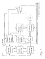
- FIG. 1 shows a block diagram of a recording device for a video device according to the invention.
- the antenna connector 11 of the receiver / demodulator 1, the connector for external video sources, such as. B. a video camera, the switch 12 and the recording device not shown below correspond to the structure of a video device according to the prior art.
- a receiver / demodulator 2 For the recording method according to the invention for recording two video channels on a tape, each of which has an image and a mono or stereo sound source, a receiver / demodulator 2, a field memory 6, 8, 9, two synchronization detectors 4, 6, a switching device 10, a control device 7, and a tone selection device 3 is required.
- the field memory is composed of an A / D converter 6, a D / A converter 9 and a digital storage device 8.
- the inputs of the receiver / demodulators 1, 2, which can be individually tuned, are connected to the same antenna connection 11. Signals appear at their outputs like they 3A and 3B. These signals have 50 or 60 fields per second. A vertical pulse occurs in each vertical blanking interval between two fields and, depending on the TV standard, a large number of line synchronizing pulses occur during a field. The vertical pulses and the line synchronizing pulses are not shown in FIG. 3.
- the signal according to FIG. 3A is fed to the synchronization detector 4 and the switching device 10, the signal according to FIG. 3B to the synchronization detector 5 and the A / D converter 6 of the field memory.
- the synchronization detectors 4, 5 pass on the vertical and line synchronization pulses of the two television program sources to the control device 7 of the field memory 6, 8, 9.
- the field characteristic pulses of the first television program source are also forwarded to the switching device 10 by the synchronization detector 4.
- the storage device 6, 8, 9 can store a complete field.
- the analog field is converted by the memory device 6, 8, 9 by means of the analog / digital converter 6 analog / digital, and after the memory device 8 by means of the digital / analog converter 9 again converted digital / analog.
- the control device 7 feeds the storage device 8 after each vertical pulse in the signal according to FIG. 3B write pulses corresponding to the line synchronizing pulses in the signal according to FIG. 3B and after each vertical pulse according to FIG. 3A read or output pulses corresponding to the line synchronizing pulses in the signal according to FIG. 3A.
- This causes every second field of the second video channel to be in the field cher 6, 8, 9 stored and simultaneously passed to the switching device 10 with each field of the first television program source.
- the switching device 10 is controlled in this way by means of the vertical pulses of the first television program source. That it inserts a field of the second television program source in the signal of FIG. 3B instead of every second field of the first television program source. This results in the signal curve according to FIG. 3C at the output of the switching device 10.
- This signal which has the same vertical and line synchronizing pulses as the signal according to FIG. 3A or 3B, is passed on to the recording device of the video device and recorded.
- the switching device 10 can be equipped with clamping stages for each input channel. If the user of the video device wants to record only one television program source, the switching device 10 can be kept constantly in the upper position according to FIG. 1.
- the sound selection device 3 is supplied by the receiver / demodulator 1, 2 with the respective sound signal from the television image source 1 and 2, which in each case consists of two channels.
- the sound channels of the first television program source are passed on to the subsequent recording device by means of the tone selection device 3.
- the tone selection device 3 When recording two television program sources, only one sound channel of a television program source is switched through from the sound channels of the two television program sources by means of the tone selection device 3 to the subsequent recording device.
- the user of the video device can use an input device, not shown, to set the tone dialing device 3 in such a way that that this passes on the desired sound channels.
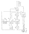
- Fig. 2 shows a block diagram of a playback device for a video device according to the invention. 3C and is applied to the inputs of an A / D converter 53 and a synchronization detector 52 and to a first input of the switching device 56. Furthermore, the audio signal consisting of two channels is applied to the audio selection device 55.
- the field memory 51, 53, 54 of the reproducing device is constructed like the field memory 6, 8, 9 of the recording device, i. H. that the fields to be stored are converted analog / digital / analog and the digital memory has at least the capacity corresponding to one field.
- the signal according to FIG. 3C again contains vertical and line synchronizing pulses, not shown, like the signals from FIGS. 3A and 3B.
- the synchronization detector 52 supplies the vertical and line synchronization pulses to the control device 50.
- a selection device 57 By means of a selection device 57, the user can set whether a first or a second television program source recorded with a recording device according to FIG. 1 or a television program source recorded with a standard method is to be reproduced.
- the selection device 57 sets the control device 50 in accordance with the desired operating mode. If standard reproduction is to be carried out, the control device 50 controls the changeover device 56 in such a way that the changeover switch is constantly held in the upper position according to FIG. 2.
- the control device 50 controls the storage device 51 in accordance with the vertical and line synchronization signals of the signal according to FIG. 3C in such a way that every second field is stored from the signal according to FIG. 3C. Since the fields of the first and second channels alternate, either all recorded fields of the first or second television program source are therefore stored in accordance with the setting of the selector 57, the fields of the television program source to be reproduced being stored in the device according to the invention.
- the field memory 51, 53, 54 is then read out in accordance with the vertical and line synchronization signals of the signal according to FIG. 3C. i.e. the stored field of the television program source to be reproduced is then applied to the second input of the switching device 56 when the field of the television program source not to be reproduced is present at the first input of the switching device 56.
- the switching device 56 is controlled by the control device 50 in accordance with the vertical pulses in such a way that it stores the fields of the television program source to be played back first in accordance with the upstream playback device and then the same field as it came from the playback device in the field memory 51, 53, 54, switches through.
- a sequence of fields according to FIG. 3D or FIG. 3E, which has 50 or 60 fields per second, thus arises at the output of the switching device 56, two successive fields being identical.
- the output signal of the switching device 50 according to FIG. 3D or 3E and the output signal of the tone selection device 55 are an output device such. B. an impedance converter circuit or an output socket.
- the sound selection device 55 is controlled by the control device 50 in such a way that it switches through both sound channels during a standard reproduction and through the sound channel associated with the reproduced television program source during a reproduction by means of the reproduction device according to the invention.
- the recording device and the playback device according to the invention can be used in a video recorder, an optical disc player or another video device for video recording or video playback if this device has two audio channels for stereo audio playback in standard operation. Furthermore, in the case of video devices which can record and / or reproduce a plurality of sound channels, a plurality of sound channels of each television picture source can of course be recorded.
- the recording device and the playback device according to the invention are arranged in a video device, the field memory, the switching device, the tone dialing device and the synchronization detectors can be used both for the recording device according to the invention and for the playback device according to the invention with suitable connection of the individual components.
- the two television program sources recorded simultaneously could also be reproduced simultaneously on two different monitors or two different monitor groups (hotel TV).
- the storage device of the playback device would have to be controlled in such a way that it successively stores the fields of both Stores video channels and the switching device is equipped with two toggle switches.
- the video device according to the second exemplary embodiment could also have two playback devices according to the invention according to FIG. 2 for this purpose.
- the switching device or the entire reproduction device could also be shifted into the monitors.
- the choice between the two video channels can only be made on the monitor.
- the recording device and the playback device according to the invention could also be used in a television transmission between the transmitter and receiver.
- the transmitter would have to work according to the principle shown in FIG. 1 and the receiver according to the principle shown in FIG. 2.
- the transmission effort and the transmission costs could then be reduced accordingly.
- Video device for recording a first and a second television program source on a recording medium, with a recording device for recording a television program source on a recording medium and with a recording device which alternately supplies the recording device with a field of the first and a field of the second television program source and continuously a sound channel of each television program source ( Fig. 1).
Abstract
Description
Die Erfindung bezieht sich auf Videogeräte gemäß den Oberbegriffen der Ansprüche 1 und 9.The invention relates to video devices according to the preambles of
Aus psychooptischen Untersuchungen ist bekannt, daß das menschliche Auge gegenüber vertikalen Auflösungsverlusten wesentlich unempfindlicher ist, als gegenüber horizontalen Auflösungsverlusten.It is known from psycho-optical studies that the human eye is significantly less sensitive to vertical loss of resolution than to horizontal loss of resolution.
Des weiteren sind Videogeräte bekannt, die auf Magnetbändern eine Fernsehprogrammquelle d. h. eine Bildquelle und mehrere Tonkanäle aufzeichnen und wiedergeben können. Derartige Videogeräte arbeiten je nach TV-Standard mit 50 oder 60 Halbbildern pro Sekunde und weisen eine eigene Empfangs- und Demodulationseinrichtung auf, um Fernsehprogrammsendungen auch dann aufzeichnen zu können, wenn kein Fernsehempfänger bzw. dessen Empfangs- und Demodulationseinrichtung zur Verfügung steht. Bei der Wiedergabe werden das Bild- und Tonsignal in der zugrundeliegenden TV-Norm, d. h. also wiederum mit 50 oder 60 Halbbildern pro Sekunde, einem Fernsehgerät oder Monitor zugeführt.Furthermore, video devices are known which can record and reproduce a television program source, ie an image source and a plurality of audio channels, on magnetic tapes. Depending on the TV standard, such video devices work with 50 or 60 fields per second and have their own reception and demodulation device in order to be able to record television program programs even when none TV receiver or its reception and demodulation device is available. During playback, the picture and sound signal in the underlying TV standard, ie again with 50 or 60 fields per second, are fed to a television or monitor.
Durch die steigende Anzahl von Fernsehprogrammen ist es häufig wünschenswert, zwei gleichzeitig gesendete Programme parallel aufzuzeichnen. Die bisherigen Videogeräte sind dazu jedoch nicht in der Lage.Due to the increasing number of television programs, it is often desirable to record two programs broadcast simultaneously. However, the previous video devices are not able to do this.
Der Erfindung liegt die Aufgabe zugrunde, ein Videogerät gemäß dem Oberbegriff des Anspruchs 1 derart weiterzubilden, daß ohne wesentliche Bildqualitätsverluste zwei Fernsehprogrammquellen auf einem Aufzeichnungsmedium gleichzeitig aufgezeichnet werden können.The invention has for its object to develop a video device according to the preamble of
Des weiteren liegt der Erfindung die Aufgabe zugrunde, ein Videogerät gemäß dem Oberbegriff des Anspruchs 9 derart weiterzubilden, daß zwei mit einem Videogerät nach Anspruch 1 aufgezeichnete Fernsehprogrammquellen einzeln ohne Bildqualitätsverluste wiedergegeben werden können.Furthermore, the invention has for its object to develop a video device according to the preamble of
Diese Aufgaben werden durch die kennzeichnenden Merkmale der Ansprüche 1 bzw. 9 gelöst.These objects are solved by the characterizing features of
Mit dem Videogerät nach Anspruch 1 können zwei Fernsehprogrammquellen gleichzeitig aufgenommen werden, ohne daß zwei Videogeräte oder zwei Aufzeichnungsmedien erforderlich werden.With the video device according to
Des weiteren wird für die Aufzeichnung zweier Fernsehprogrammquellen nicht mehr Aufzeichnungsmaterial benötigt, wie bisher für die Aufzeichnung einer Fernsehprogrammquelle.Furthermore, recording material is no longer required for recording two television program sources, as was previously the case for recording one television program source.
Mit dem Videogerät nach Anspruch 9 kann wahlweise einer der beiden Fernsehprogrammquellen wiedergegeben werden.With the video device according to
Durch die Merkmale der Ansprüche 17 oder 18 können des weiteren beide Fernsehprogrammquellen gleichzeitig auf verschiedenen Monitoren oder Fernsehgeräten wiedergegeben werden.Due to the features of claims 17 or 18, furthermore, both television program sources can be reproduced simultaneously on different monitors or television sets.
Des weiteren sind mit den Videogeräten nach Anspruch 1 und 9 weiterhin Aufnahmen und Wiedergaben im Standardvideoverfahren möglich.Furthermore, recordings and reproductions in the standard video process are also possible with the video devices according to
Die Erfindung macht von der Erkenntnis Gebrauch, daß das Auge gegen vertikale Auflösungsverluste relativ unempfindlich ist. Der Betrachter eines Fernsehbildes, das aus zwei aufeinanderfolgenden Halbbildern mit insgesamt 625 Zeilen besteht, wobei ein Halbbild die ungeraden Zeilen und ein Halbbild die geraden Zeilen bildet, kann daher keinen horizontalen Auflösungsverlust feststellen, wenn das Fernsehbild aus zwei gleichen Halbbildern gebildet wird.The invention makes use of the knowledge that the eye is relatively insensitive to vertical loss of resolution. The viewer of a television picture consisting of two successive fields with a total of 625 lines, one field forming the odd lines and one field forming the even lines, can therefore not see any horizontal loss of resolution if the television picture is formed from two identical fields.
Werden mit dem Videogerät nach Anspruch 1 zwei Spielfilme aufgezeichnet, die bereits mit 25 Bildern pro Sekunde hergestellt werden, so sind bei der Wiedergabe dieser Aufzeichnung mit einem Videogerät nach Anspruch 9 praktisch keine Qualitätseinbußen feststellbar.If two films are recorded with the video device according to
Bei Aufzeichnungen, die mit einer Videokamera hergestellt wurden, reduziert sich die Bildqualität der Aufzeichnung lediglich auf die Bildqualität eines Spielfilms.In the case of recordings which were produced with a video camera, the image quality of the recording is reduced only to the image quality of a feature film.
In den übrigen Unteransprüchen sind weitere vorteilhafte Weiterbildungen der Erfindung angegeben.Further advantageous developments of the invention are specified in the remaining subclaims.
Die Erfindung wird nachstehend anhand eines Ausführungsbeispiels unter Bezugnahme auf die Zeichnung näher erläutert. Es zeigt:
- Fig. 1 ein Blockschaltbild einer Aufnahmevorrichtung gemäß einem ersten Ausführungsbeispiel des erfindungsgemäßen Videogerätes;
- Fig. 2 ein Blockschaltbild einer Wiedergabevorrichtung gemäß einem ersten Ausführungsbeispiel des erfindungsgemäßen Videogerätes;
- Fig. 3 ein Bildsignalabfolgediagramm für die Aufnahme- und Wiedergabevorrichtung gemäß Fig. 1 und 2.
- Figure 1 is a block diagram of a recording device according to a first embodiment of the video device according to the invention.
- 2 shows a block diagram of a playback device according to a first exemplary embodiment of the video device according to the invention;
- 3 shows an image signal sequence diagram for the recording and reproducing device according to FIGS. 1 and 2.
Fig. 1 zeigt ein Blockschaltbild einer Aufnahmevorrichtung für ein erfindungsgemäßes Videogerät. Der Antennenanschluß 11 der Empfänger/Demodulator 1, der Anschluß für externe Videoquellen, wie z. B. eine Videokamera, der Umschalter 12 sowie die nachfolgend nicht gezeigte Aufzeichnungseinrichtung entsprechen dem Aufbau eines Videogerätes gemäß dem Stand der Technik. Für das erfindungsgemäße Aufnahmeverfahren zur Aufnahme zweier Videokanäle auf ein Band, von denen jeder eine Bild- und eine Mono- oder Stereotonquelle aufweisen, wird darüber hinaus noch ein Empfänger/Demodulator 2, ein Halbbildspeicher 6, 8, 9, zwei Synchronisationsdetektoren 4, 6, eine Umschalteinrichtung 10, eine Steuereinrichtung 7, und eine Tonwähleinrichtung 3 benötigt. Der Halbbildspeicher ist aus einem A/D-Wandler 6, einem D/A-Wandler 9 sowie einer Digitalspeichereinrichtung 8 aufgebaut.1 shows a block diagram of a recording device for a video device according to the invention. The antenna connector 11 of the receiver /
Die Eingänge der Empfänger/Demodulatoren 1, 2, die einzeln abstimmbar sind, sind mit demselben Antennenanschluß 11 verbunden. An ihren Ausgängen entstehen Signale, wie sie in Fig. 3A und 3B gezeigt sind. Diese Signale weisen 50 oder 60 Halbbilder pro Sekunde auf. ln jeder vertikalen Austastlücke zwischen zwei Halbbildern erfolgt ein Vertikalimpuls, und während eines Halbbildes erfolgen je nach TV-Standard eine Vielzahl von Zeilensynchronimpulsen. Die Vertikalimpulse und die Zeilensynchronimpulse sind in Fig. 3 nicht dargestellt.The inputs of the receiver /
Das Signal nach Fig. 3A wird dem Synchronisationsdetektor 4 und der Umschalteinrichtung 10, das Signal nach Fig. 3B dem Synchronisationsdetektor 5 und dem A/D-Wandler 6 des Halbbildspeichers zugeführt.The signal according to FIG. 3A is fed to the synchronization detector 4 and the
Die Synchronisationsdetektoren 4, 5 geben die Vertikal- und Zeilensynchronimpulse der beiden Fernsehprogrammquellen an die Steuereinrichtung 7 des Halbbildspeichers 6, 8, 9 weiter. Von dem Synchronisationsdetektor 4 werden des weiteren die Halbbildkennimpulse der ersten Fernsehprogrammquelle an die Umschalteinrichtung 10 weitergegeben.The synchronization detectors 4, 5 pass on the vertical and line synchronization pulses of the two television program sources to the control device 7 of the
Die Speichereinrichtung 6, 8, 9 kann ein komplettes Halbbild speichern. Das analoge Halbbild wird von der Speichereinrichtung 6, 8, 9 mittels des Analog/Digital-Wandlers 6 analog/digital gewandelt, und nach der Speichereinrichtung 8 mittels des Digital/Analog-Wandlers 9 wieder digital/analog gewandelt.The
Die Steuereinrichtung 7 führt der Speichereinrichtung 8 nach jedem Vertikalimpuls im Signal nach Fig. 3B Schreibimpulse entsprechend der Zeilensynchronimpulse im Signal nach Fig. 3B und nach jedem Vertikalimpuls nach Fig. 3A Lese- bzw. Ausgabeimpulse entsprechend der Zeilensynchronimpulse im Signal nach Fig. 3A zu. Dadurch wird jedes zweite Halbbild des zweiten Videokanals im Halbbildspei cher 6, 8, 9 gespeichert und gleichzeitig mit jedem Halbbild der ersten Fernsehprogrammquelle an die Umschalteinrichtung 10 weitergegeben.The control device 7 feeds the storage device 8 after each vertical pulse in the signal according to FIG. 3B write pulses corresponding to the line synchronizing pulses in the signal according to FIG. 3B and after each vertical pulse according to FIG. 3A read or output pulses corresponding to the line synchronizing pulses in the signal according to FIG. 3A. This causes every second field of the second video channel to be in the field cher 6, 8, 9 stored and simultaneously passed to the
Die Umschalteinrichtung 10 wird mittels der Vertikalimpulse der ersten Fernsehprogrammquelle derart gesteuert. daß sie in das Signal nach Fig. 3B anstelle jedes zweiten Halbbildes der ersten Fernsehprogrammquelle ein Halbbild der zweiten Fernsehprogrammquelle einsetzt. Dadurch ergibt sich am Ausgang der Umschalteinrichtung 10 der Signalverlauf nach Fig. 3C. Dieses Signal, das dieselben Vertikal- und Zeilensynchronimpule aufweist, wie das Signal nach Fig. 3A oder 3B, wird an die Aufzeichnungseinrichtung des Videogerätes weitergegeben und aufgezeichnet. Um Potentialsprünge in dem zusammengesetzten Signal zu vermeiden, kann die Umschalteinrichtung 10 mit Klemmstufen für jeden Eingangskanal ausgestattet sein. Will der Benutzer des Videogerätes nur eine Fernsehprogrammquelle aufzeichnen, so kann die Umschalteinrichtung 10 ständig in der oberen Position nach Fig. 1 gehalten werden.The
Der Tonwähleinrichtung 3 wird von dem Empfänger/Demodulator 1, 2 das jeweilige Tonsignal der Fernsehbildquelle 1 und 2 zugeführt, das jeweils aus zwei Kanälen besteht. Bei Standardaufzeichnung, also bei Aufzeichnung nur einer einzigen Fernsehprogrammquelle werden die Tonkanäle der ersten Fernsehprogrammquelle mittels der Tonwahleinrichtung 3 an die nachfolgende Aufzeichnungseinrichtung weitergegeben. Bei Aufzeichnung zweier Fernsehprogrammquellen wird von den Tonkanälen der beiden Fernsehprogrammquellen mittels der Tonwähleinrichtung 3 nur jeweils ein Tonkanal einer Fernsehprogrammquelle auf die nachfolgende Aufzeichnungseinrichtung durchgeschaltet. Der Benutzer des Videogerätes kann mittels einer nicht gezeigten Eingabeeinrichtung die Tonwähleinrichtung 3 derart einstellen, daß diese die gewünschten Tonkanäle weitergibt.The sound selection device 3 is supplied by the receiver /
Fig. 2 zeigt ein Blockschaltbild einer Wiedergabevorrichtung für ein erfindungsgemäßes Videogerät. Der Wiedergabevorrichtung wird das Bildsignal gemäß Fig. 3C zugeführt und an die Eingänge eines A/D-Wandlers 53 und eines Synchronisationsdetektors 52 sowie an einen ersten Eingang der Umschalteinrichtung 56 angelegt. Des weiteren wird das aus zwei Kanälen bestehende Tonsignal an die Tonwähleinrichtung 55 angelegt.Fig. 2 shows a block diagram of a playback device for a video device according to the invention. 3C and is applied to the inputs of an A /
Der Halbbildspeicher 51. 53, 54 der wiedergabevorrichtung ist wie der Halbbildspeicher 6, 8, 9 der Aufnahmevorrichtung aufgebaut, d. h. daß die zu speichernden Halbbilder analog/digital/analog gewandelt werden und der Digitalspeicher mindestens die einem Halbbild entsprechende Kapazität hat.The
Das Signal nach Fig. 3C beinhaltet wiederum nicht gezeigte Vertikal- und Zeilensynchronimpulse wie die Signale der Fig. 3A und 3B. Der Synchronisationsdetektor 52 führt die Vertikal- und Zeilensynchronimpulse der Steuereinrichtung 50 zu.The signal according to FIG. 3C again contains vertical and line synchronizing pulses, not shown, like the signals from FIGS. 3A and 3B. The
Mittels einer Wähleinrichtung 57 kann der Benutzer einstellen, ob eine erste oder zweite mit einer Aufnahmevorrichtung gemäß Fig. 1 aufgezeichnete oder eine mit einem Standardverfahren aufgezeichnete Fernsehprogrammquelle wiedergegeben werden soll. Die Wähleinrichtung 57 stellt die Steuereinrichtung 50 entsprechend der gewünschten Betriebsart ein. Soll eine Standardwiedergabe ausgeführt werden, so steuert die Steuereinrichtung 50 die Umschalteinrichtung 56 derart an, daß der Umschalter ständig in der oberen Position nach Fig. 2 gehalten wird.By means of a
Bei Wiedergabe einer mittels einer Aufzeichnungsvorrichtung gemäß Fig. 1 aufgezeichneten Fernsehprogrammquelle steuert die Steuereinrichtung 50 die Speichereinrichtung 51 entsprechend der Vertikal- und Zeilensynchronisiersignale des Signals nach Fig. 3C derart, daß aus dem Signal nach Fig. 3C jedes zweite Halbbild gespeichert wird. Da sich die Halbbilder des ersten und zweiten Kanals abwechseln, werden daher entsprechend der Einstellung der Wähleinrichtung 57 entweder alle aufgezeichneten Halbbilder der ersten oder zweiten Fernsehprogrammquelle gespeichert, wobei in der erfindungsgemäßen Vorrichtung die Halbbilder der wiederzugebenden Fernsehprogrammquelle gespeichert werden. Der Halbbildspeicher 51, 53, 54 wird entsprechend der Vertikal- und Zeilensynchronisiersignale des Signals nach Fig. 3C dann ausgelesen. d.h. das gespeicherte Halbbild der wiederzugebenden Fernsehprogrammquelle wird dann an den zweiten Eingang der Umschalteinrichtung 56 angelegt, wenn das Halbbild der nicht wiederzugebenden Fernsehprogrammquelle am ersten Eingang der Umschalteinrichtung 56 anliegt.1, the
Dabei wird die Umschalteinrichtung 56 durch die Steuereinrichtung 50 nach Maßgabe der Vertikalimpulse derart gesteuert, daß sie die Halbbilder der wiederzugebenden Fernsehprogrammquelle zuerst entsprechend der vorgeschalteten Wiedergabeeinrichtung und dann dasselbe Halbbild nocheinmal wie es von der Wiedergabeeinrichtung kommend in dem Halbbildspeicher 51, 53, 54 gespeichert wurde, durchschaltet. Somit entsteht am Ausgang der Umschalteinrichtung 56 eine Folge von Halbbildern gemäß Fig. 3D oder Fig. 3E, die 50 oder 60 Halbbilder pro Sekunde aufweist, wobei jeweils zwei aufeinanderfolgende Halbbilder gleich sind.The switching
Das Ausgangssignal der Umschalteinrichtung 50 gemäß Fig. 3D oder 3E und das Ausgangssignal der Tonwähleinrichtung 55 werden einer Ausgangseinrichtung, wie z. B. einer Impedanzwandlerschaltung oder einer Ausgangsbuchse zugeführt. Die Tonwähleinrichtung 55 wird von der Steuereinrichtung 50 derart gesteuert, daß sie bei einer Standardwiedergabe beide Tonkanäle und bei einer Wiedergabe mittels der erfindungsgemäßen Wiedergabevorrichtung den zu der wiedergegebenen Fernsehprogrammquelle gehörigen Tonkanal durchschaltet.The output signal of the
Die erfindungsgemäße Aufnahmevorrichtung und die erfindungsgemäße Wiedergabevorrichtung kann bei einem Videorecorder, einem Bildplattenspieler oder einem anderem Videogerät zur Videoaufzeichnung bzw. Videowiedergabe Anwendung finden, wenn dieses Gerät zwei Tonkanäle für Stereotonwiedergabe bei Standardbetrieb hat. Des weiteren können bei Videogeräten, die mehrere Tonkanäle aufzeichnen und/oder wiedergeben können, selbstverständlich mehrere Tonkanäle jeder Fernsehbildquelle aufgezeichnet werden.The recording device and the playback device according to the invention can be used in a video recorder, an optical disc player or another video device for video recording or video playback if this device has two audio channels for stereo audio playback in standard operation. Furthermore, in the case of video devices which can record and / or reproduce a plurality of sound channels, a plurality of sound channels of each television picture source can of course be recorded.
Wird die erfindungsgemäße Aufzeichnungsvorrichtung und die erfindungsgemäße Wiedergabevorrichtung in einem Videogerät angeordnet, so kann bei geeigneter Verschaltung der einzelnen Komponenten der Halbbildspeicher, die Umschalteinrichtung, die Tonwähleinrichtung und die Synchronisationsdetektoren sowohl für die erfindungsgemäße Aufnahmevorrichtung als auch für die erfindungsgemäße Wiedergabevorrichtung verwendet werden.If the recording device and the playback device according to the invention are arranged in a video device, the field memory, the switching device, the tone dialing device and the synchronization detectors can be used both for the recording device according to the invention and for the playback device according to the invention with suitable connection of the individual components.
Gemäß einem zweiten Ausführungsbeispiel der Erfindung könnten die beiden gleichzeitig aufgezeichneten Fernsehprogrammquellen auch gleichzeitig auf zwei verschiedenen Monitoren oder zwei verschiedenen Monitorgruppen (Hotel-TV) wiedergegeben werden. Dazu müßte die Speichereinrichtung der Wiedergabevorrichtung derart gesteuert werden, daß sie aufeinanderfolgend die Halbbilder beider Videokanäle speichert und die Umschalteinrichtung mit zwei Wechselschaltern ausgestattet ist. Bei sinkenden Kosten für Halbleiterspeicher könnte zu diesem Zweck das Videogerät gemäß des zweiten Ausführungsbeispiels auch zwei erfindungsgemäße Wiedergabevorrichtungen gemäß Fig. 2 aufweisen.According to a second exemplary embodiment of the invention, the two television program sources recorded simultaneously could also be reproduced simultaneously on two different monitors or two different monitor groups (hotel TV). For this purpose, the storage device of the playback device would have to be controlled in such a way that it successively stores the fields of both Stores video channels and the switching device is equipped with two toggle switches. With falling costs for semiconductor memories, the video device according to the second exemplary embodiment could also have two playback devices according to the invention according to FIG. 2 for this purpose.
Des weiteren könnte bei diesem zweiten Ausführungsbeispiel die Umschalteinrichtung oder die gesamte Wiedergabevorrichtung auch in die Monitore verlagert werden. In diesem Fall könnte z. B. beim Hotel-TV die Wahl zwischen den beiden Videokanälen auch erst am Monitor vorgenommen werden.Furthermore, in this second exemplary embodiment, the switching device or the entire reproduction device could also be shifted into the monitors. In this case, e.g. B. in hotel TV, the choice between the two video channels can only be made on the monitor.
Gemäß einem dritten Ausführungsbeispiel könnte die erfindungsgemäße Aufnahmevorrichtung und die erfindungsgemäße Wiedergabevorrichtung auch bei einer Fernsehübertragung zwischen dem Sender und Empfänger eingesetzt werden. Dabei müßte der Sender nach dem in Fig. 1 dargestellten Prinzip und der Empfänger nach dem in Fig. 2 dargestellten Prinzip arbeiten. Bei Satellitenübertragungen könnte der Übertragungsaufwand und die Übertragungskosten dann entsprechend reduziert werden.According to a third exemplary embodiment, the recording device and the playback device according to the invention could also be used in a television transmission between the transmitter and receiver. The transmitter would have to work according to the principle shown in FIG. 1 and the receiver according to the principle shown in FIG. 2. In the case of satellite transmissions, the transmission effort and the transmission costs could then be reduced accordingly.
Videogerät zur Aufzeichnung einer ersten und einer zweiten Fernsehprogrammquelle auf einem Aufzeichnungsmedium, mit einer Aufzeichnungseinrichtung zur Aufzeichnung einer Fernsehprogrammquelle auf einem Aufzeichnungsmedium und mit einer Aufnahmevorrichtung, die der Aufzeichnungseinrichtung alternierend ein Halbbild der ersten und ein Halbbild der zweiten Fernsehprogrammquelle und kontinuierlich einen Tonkanal jeder Fernsehprogrammquelle zuführt (Fig. 1).Video device for recording a first and a second television program source on a recording medium, with a recording device for recording a television program source on a recording medium and with a recording device which alternately supplies the recording device with a field of the first and a field of the second television program source and continuously a sound channel of each television program source ( Fig. 1).
Claims (20)
gekennzeichnet durch
eine Aufnahmevorrichtung, die der Aufzeichnungseinrichtung alternierend ein Halbbild der ersten und ein Halbbild der zweiten Fernsehprogrammquelle und kontinuierlich einen Tonkanal jeder Fernsehprogrammquelle zuführt.1. Video device for recording a first and a second television program source on a recording medium, with a recording device for recording a television program source on a recording medium,
marked by
a recording device which alternately supplies the recording device with a field of the first and a field of the second television program source and continuously a sound channel of each television program source.
gekennzeichnet durch
eine zweite Empfangs- und Demodulationseinrichtung (2).2. Video device according to claim 1, with a first receiving and demodulating device (1),
marked by
a second receiving and demodulating device (2).
dadurch gekennzeichnet, daß
die Aufnahmevorrichtung einen Halbbildspeicher (6, 8, 9), eine Umschalteinrichtung (10), die der Aufzeichnungsein richtung alternierend ein Halbbild der ersten Fernsehprogrammquelle und ein in dem Halbbildspeicher gespeichertes Halbbild der zweiten Fernsehprogrammquelle zuführt und eine Steuereinrichtung (7) umfaßt, die den Halbbildspeicher derart steuert, daß dieser jedes zweite Halbbild der zweiten Fernsehprogrammquelle speichert und diese Halbbilder zeitgleich mit den zweiten Halbbildern der ersten Fernsehprogrammquelle an die Umschalteinrichtung ausgibt.3. Video device according to claim 1 or 2,
characterized in that
the recording device comprises a field memory (6, 8, 9), a switching device (10) which is used for recording alternately one field of the first television program source and a field stored in the field memory of the second television program source and comprises a control device (7) which controls the field memory in such a way that it stores every second field of the second television program source and these fields simultaneously with the second fields of the outputs the first television program source to the switching device.
dadurch gekennzeichnet, daß
ein erster Synchronisationsdetektor (4) die Vertikalimpulse der ersten Fernsehprogrammquelle als Umschaltsignal an die Umschalteinrichtung und die Vertikalimpulse und die Zeilensynchronimpulse der ersten Fernsehprogrammquelle zur Bildung von Lese- bzw. Ausgabesignale an die Steuereinrichtung weitergibt, und daß ein zweiter Synchronisationsdetektor (5) die Vertikalimpulse und die Zeilensynchronimpulse der zweiten Fernsehprogrammquelle zur Bildung von Schreibimpulsen an die Steuereinrichtung weitergibt.4. Video device according to claim 3,
characterized in that
a first synchronization detector (4) transmits the vertical pulses of the first television program source as a switching signal to the switching device and the vertical pulses and the line synchronization pulses of the first television program source to form read or output signals to the control device, and that a second synchronization detector (5) transmits the vertical pulses and Line sync pulses from the second television program source to form write pulses to the control device.
dadurch gekennzeichnet, daß
der Halbbildspeicher ein Digitalspeicher ist, der an seinem Eingang einen Analog/Digital-Wandler (6) und an seinem Ausgang einen Digital/Analog-Wandler (9) hat.5. Video device according to claim 3 or 4,
characterized in that
the field memory is a digital memory which has an analog / digital converter (6) at its input and a digital / analog converter (9) at its output.
eine Tonwähleinrichtung (3) einen Tonkanal jeder Fernsehprogrammquelle oder beide Tonkanäle einer Fernsehprogrammquelle an die Aufzeichnungseinrichtung weitergibt.6. Video device according to one of the preceding claims, characterized in that
a sound selection device (3) forwards a sound channel of each television program source or both sound channels of a television program source to the recording device.
dadurch gekennzeichnet, daß
die Tonwähleinrichtung durch eine Eingabeeinrichtung eingestellt wird.7. Video device according to claim 6,
characterized in that
the tone dialing device is set by an input device.
dadurch gekennzeichnet, daß
die Umschalteinrichtung in einer festen Position gehalten werden kann, so daß Standardvideoaufzeichnungen ebenfalls möglich sind.8. Video device according to claim 2, 3, 4, 5, 6 or 7,
characterized in that
the switching device can be held in a fixed position, so that standard video recordings are also possible.
gekennzeichnet durch eine Wiedergabevorrichtung, die der Ausgangseinrichtung jedes Halbbild des wiederzugebenden Kanals zweimal aufeinanderfolgend zusammen mit dem Tonkanal des wiederzugebenden Kanals zuführt.9. Video device for reproducing a first and a second television program source, the fields of which alternate and the sound channels of which are continuously recorded on a recording medium, with a reproducing device for removing the image and sound information from the recording medium and an output device,
characterized by a reproducing device which feeds to the output device each field of the channel to be reproduced twice in succession together with the sound channel of the channel to be reproduced.
dadurch gekennzeichnet, daß
die Wiedergabevorrichtung einen Halbbildspeicher (51, 53, 54),
eine Umschalteinrichtung (56), die der Ausgangseinrichtung alternierend ein Halbbild der wiederzugebenden Fernsehprogrammquelle aus der Wiedereingabeeinrichtung und dasselbe Halbbild darauffolgend aus dem Halbbildspeicher zuführt und
eine Steuereinrichtung (50) umfaßt, die den Halbbildspeicher derart steuert, daß dieser jedes Halbbild der wiederzugebenden Fernsehbildquelle speichert und diese Halbbil der zeitgleich mit den Halbbildern der nicht wiederzugebenden Fernsehprogrammquelle an die Umschalteinrichtung ausgibt.10. Video device according to claim 9,
characterized in that
the playback device has a field memory (51, 53, 54),
a switching device (56) which alternately supplies the output device with a field of the television program source to be reproduced from the re-input device and the same field subsequently from the field memory and
a control device (50) which controls the field memory in such a way that it stores each field of the television picture source to be reproduced and this field which outputs to the switching device at the same time as the fields of the television program source which is not to be reproduced.
dadurch gekennzeichnet, daß
ein Synchronisationsdetektor (52) die Vertikalimpulse und Zeilensynchronimpulse der wiederzugebenden und nicht wiederzugebenden Fernsehprogrammquelle zur Bildung von Schreibsignalen und Lese- bzw. Ausgabesignalen an die Steuereinrichtung weitergibt.11. Video device according to claim 10,
characterized in that
a synchronization detector (52) forwards the vertical pulses and line synchronizing pulses of the television program source to be reproduced and not reproduced to form write signals and read or output signals to the control device.
dadurch gekennzeichnet, daß
der Halbbildspeicher ein Digitalspeicher (51) ist, der an seinem Eingang einen Analog/Digital-Wandler (53) und an seinem Ausgang einen Digital/Analog-Wandler (54) hat.12. Video device according to claim 10 or 11,
characterized in that
the field memory is a digital memory (51) which has an analog / digital converter (53) at its input and a digital / analog converter (54) at its output.
dadurch gekennzeichnet, daß
mittels einer Wähleinrichtung (57) die Steuereinrichtung so eingestellt wird, daß entweder die erste oder zweite Fernsehprogrammquelle oder eine Standardvideoaufzeichnung wiedergegeben wird.13. Video device according to claim 10, 11 or 12,
characterized in that
by means of a selection device (57) the control device is set in such a way that either the first or second television program source or a standard video recording is reproduced.
dadurch gekennzeichnet, daß
die Steuereinrichtung der Umschalteinrichtung bei Wiedergabe einer der beiden Fernsehprogrammquellen im Halbbildrhythmus ein Umschaltsignal und bei einer Standardwiedergabe ein konstantes Signal zuführt, durch das die Umschalteinrichtung der Ausgangseinrichtung ständig ein Standardvideosignal von der Wiedergabeeinrichtung zuführt.14. Video device according to claim 10, 11, 12 or 13,
characterized in that
the control device supplies the switchover device with a switchover signal when playing one of the two television program sources in the field rhythm and with a standard display a constant signal through which the switchover device continuously supplies the output device with a standard video signal from the playback device.
dadurch gekennzeichnet, daß
die Steuereinrichtung eine Tonwähleinrichtung (55) derart einstellt, daß diese den Tonkanal der wiederzugebenden Fernsehprogrammquelle von der Wiedergabeeinrichtung an die Ausgangseinrichtung weitergibt.15. Video device according to claim 10, 11, 12, 13 or 14,
characterized in that
the control device sets a tone selection device (55) such that it passes on the sound channel of the television program source to be played back from the playback device to the output device.
dadurch gekennzeichnet, daß
die Steuereinrichtung die Tonwähleinrichtung bei Standardvideowiedergabe derart einstellt, daß diese beide Tonkanäle von der Wiedergabeeinrichtung an die Ausgangseinrichtung weitergibt.16. Video device according to claim 10, 11, 12, 13, 14 or 15,
characterized in that
the control device sets the tone selection device for standard video playback in such a way that it passes on both sound channels from the playback device to the output device.
dadurch gekennzeichnet, daß
mittels einer zweiten Umschalteinrichtung beide Fernsehprogrammquellen an die Ausgabeeinrichtung weitergegeben werden können.17. Video device according to claim 9,
characterized in that
by means of a second switching device, both television program sources can be passed on to the output device.
dadurch gekennzeichnet, daß
mittels einer zweiten Wiedergabevorrichtung beide Fernsehprogrammquellen an die Ausgabeeinrichtung weitergegeben werden können.18. Video device according to claim 9,
characterized in that
Both television program sources can be passed on to the output device by means of a second playback device.
dadurch gekennzeichnet, daß
die Ausgabeeinrichtung ein Impedanzwandler oder eine Ausgangsbuchse ist.19. Video device according to claim 9, 10, 11, 12, 13, 14, 15, 16, 17 or 18,
characterized in that
the output device is an impedance converter or an output socket.
eine Aufnahmevorrichtung und
eine Wiedergabevorrichtung.20. Video device according to one of the preceding claims, characterized by
a cradle and
a playback device.
Applications Claiming Priority (2)
| Application Number | Priority Date | Filing Date | Title |
|---|---|---|---|
| DE19893934635 DE3934635C1 (en) | 1989-10-17 | 1989-10-17 | |
| DE3934635 | 1989-10-17 |
Publications (2)
| Publication Number | Publication Date |
|---|---|
| EP0423652A2 true EP0423652A2 (en) | 1991-04-24 |
| EP0423652A3 EP0423652A3 (en) | 1992-06-17 |
Family
ID=6391649
Family Applications (1)
| Application Number | Title | Priority Date | Filing Date |
|---|---|---|---|
| EP19900119632 Withdrawn EP0423652A3 (en) | 1989-10-17 | 1990-10-12 | Video device for two television programme sources |
Country Status (3)
| Country | Link |
|---|---|
| EP (1) | EP0423652A3 (en) |
| JP (1) | JPH03208481A (en) |
| DE (1) | DE3934635C1 (en) |
Cited By (4)
| Publication number | Priority date | Publication date | Assignee | Title |
|---|---|---|---|---|
| GB2262202A (en) * | 1991-11-26 | 1993-06-09 | Gold Star Co | Recording two video signals onto a single recording medium |
| WO1994016524A1 (en) * | 1993-01-11 | 1994-07-21 | Bre.In. Brevetti Internazionali S.P.A. | A system for composition/decomposition of video signals to enable to transmit/receive and to record/playback contemporaneously two tv programs |
| FR2713863A1 (en) * | 1993-12-13 | 1995-06-16 | France Etat Armement | Video signal recording and combination system e.g. for aircraft navigation or firing |
| GB2308257A (en) * | 1994-12-12 | 1997-06-18 | Jacob Ezra | Twin channel video recording |
Families Citing this family (1)
| Publication number | Priority date | Publication date | Assignee | Title |
|---|---|---|---|---|
| KR930009699B1 (en) * | 1990-09-19 | 1993-10-08 | 삼성전자 주식회사 | Playing-back circuit in video reproduction system |
Citations (7)
| Publication number | Priority date | Publication date | Assignee | Title |
|---|---|---|---|---|
| US3686436A (en) * | 1969-12-30 | 1972-08-22 | Iit Res Inst | Multiple video signal transducing system and method |
| US4326220A (en) * | 1979-09-05 | 1982-04-20 | Sony Corporation | Television receiver |
| US4656527A (en) * | 1983-11-25 | 1987-04-07 | Victor Company Of Japan, Limited | Magnetic recording and playback apparatus |
| DE3702814A1 (en) * | 1986-01-31 | 1987-08-06 | Canon Kk | Recording and/or replay device |
| US4758901A (en) * | 1986-10-28 | 1988-07-19 | Eastman Kodak Company | Continuous audio recording in a skip-field video recorder |
| US4774597A (en) * | 1986-07-28 | 1988-09-27 | Eastman Kodak Company | Quadrature head dual channel VCR |
| US4847690A (en) * | 1987-02-19 | 1989-07-11 | Isix, Inc. | Interleaved video system, method and apparatus |
Family Cites Families (9)
| Publication number | Priority date | Publication date | Assignee | Title |
|---|---|---|---|---|
| US3395248A (en) * | 1963-10-19 | 1968-07-30 | Japan Broadcasting Corp | Slow motion reproduction of transversely recorded television signals |
| DE1816041B2 (en) * | 1968-12-20 | 1971-03-25 | Telefunken Patentverwertungsgesell schaft mbH 790OUIm | MAGNETIC TAPE DEVICE FOR RECORDING AND OR REPLAYING TELEVISION SIGNALS |
| ATA871375A (en) * | 1975-11-14 | 1976-06-15 | Eumig | SYSTEM FOR THE STORAGE AND PLAYBACK OF TELEVISION SIGNALS FROM MULTIPLE SIGNAL SOURCES |
| DE3216320A1 (en) * | 1982-05-03 | 1983-11-10 | Grundig E.M.V. Elektro-Mechanische Versuchsanstalt Max Grundig & Co KG, 8510 Fürth | Method for recording and replaying television signals |
| DE3234846C2 (en) * | 1982-09-21 | 1984-12-13 | Carl Werner 2000 Hamburg Neumann | Video tape recorder |
| JPH0815332B2 (en) * | 1985-04-18 | 1996-02-14 | 三菱電機株式会社 | Magnetic recording / reproducing device |
| JPS6339284A (en) * | 1986-08-04 | 1988-02-19 | Mitsubishi Electric Corp | Magnetic recording and reproducing device |
| JPS6444688A (en) * | 1987-08-13 | 1989-02-17 | Sharp Kk | Recording and reproducing device |
| DE3842264A1 (en) * | 1987-12-15 | 1989-07-06 | Gold Star Co | Simultaneous dual video signal recording arrangement for video cassette recorders |
-
1989
- 1989-10-17 DE DE19893934635 patent/DE3934635C1/de not_active Revoked
-
1990
- 1990-10-12 EP EP19900119632 patent/EP0423652A3/en not_active Withdrawn
- 1990-10-16 JP JP2277605A patent/JPH03208481A/en active Pending
Patent Citations (7)
| Publication number | Priority date | Publication date | Assignee | Title |
|---|---|---|---|---|
| US3686436A (en) * | 1969-12-30 | 1972-08-22 | Iit Res Inst | Multiple video signal transducing system and method |
| US4326220A (en) * | 1979-09-05 | 1982-04-20 | Sony Corporation | Television receiver |
| US4656527A (en) * | 1983-11-25 | 1987-04-07 | Victor Company Of Japan, Limited | Magnetic recording and playback apparatus |
| DE3702814A1 (en) * | 1986-01-31 | 1987-08-06 | Canon Kk | Recording and/or replay device |
| US4774597A (en) * | 1986-07-28 | 1988-09-27 | Eastman Kodak Company | Quadrature head dual channel VCR |
| US4758901A (en) * | 1986-10-28 | 1988-07-19 | Eastman Kodak Company | Continuous audio recording in a skip-field video recorder |
| US4847690A (en) * | 1987-02-19 | 1989-07-11 | Isix, Inc. | Interleaved video system, method and apparatus |
Cited By (6)
| Publication number | Priority date | Publication date | Assignee | Title |
|---|---|---|---|---|
| GB2262202A (en) * | 1991-11-26 | 1993-06-09 | Gold Star Co | Recording two video signals onto a single recording medium |
| GB2262202B (en) * | 1991-11-26 | 1995-08-02 | Gold Star Co | Video cassette recorder |
| WO1994016524A1 (en) * | 1993-01-11 | 1994-07-21 | Bre.In. Brevetti Internazionali S.P.A. | A system for composition/decomposition of video signals to enable to transmit/receive and to record/playback contemporaneously two tv programs |
| FR2713863A1 (en) * | 1993-12-13 | 1995-06-16 | France Etat Armement | Video signal recording and combination system e.g. for aircraft navigation or firing |
| GB2308257A (en) * | 1994-12-12 | 1997-06-18 | Jacob Ezra | Twin channel video recording |
| GB2308257B (en) * | 1994-12-12 | 1999-03-24 | Jacob Ezra | Method and apparatus for recording over a prerecorded video signal |
Also Published As
| Publication number | Publication date |
|---|---|
| JPH03208481A (en) | 1991-09-11 |
| EP0423652A3 (en) | 1992-06-17 |
| DE3934635C1 (en) | 1991-02-21 |
Similar Documents
| Publication | Publication Date | Title |
|---|---|---|
| DE3623719C2 (en) | ||
| DE3885815T3 (en) | Digital signal transmission device. | |
| DE3114631C2 (en) | ||
| DE3401678C2 (en) | Viewer for the compilation of video images | |
| AT395666B (en) | METHOD FOR PROCESSING VIDEO DATA IN A RECORDING AND / OR PLAYBACK DEVICE | |
| DE3305090A1 (en) | REMOTE CONTROL SYSTEM | |
| EP0737405B1 (en) | Method and device for the recording and reproduction of stereoscopic video images | |
| DE2334079A1 (en) | MAGNETIC RECORDING AND SCANNING DEVICE FOR VIDEO SIGNALS | |
| DE3232872C2 (en) | Device for recording and reproducing digital time-division multiplexed audio and video signals | |
| EP0306704B1 (en) | Circuit arrangement for a television receiver to switch between television channels without interference | |
| DE2849791A1 (en) | METHOD AND DEVICE FOR RECORDING STANDING IMAGES | |
| DE3017658A1 (en) | IMAGE PLAYER | |
| DE2637642B2 (en) | DEVICE FOR COMPENSATING SIGNAL ERRORS IN A RECORDING / PLAYBACK DEVICE FOR VIDEO SIGNALS | |
| DE2849180C2 (en) | ||
| DE2344340C3 (en) | Signal transmission system, especially still image transmission system | |
| DE3311602C2 (en) | Digital signal recording and reproducing apparatus | |
| DE3623576A1 (en) | METHOD AND DEVICE FOR ELECTRONIC TRANSMISSION AND / OR RECORDING AND SUBSEQUENT PLAYBACK OF STEREOSCOPIC TELEVISION IMAGES | |
| DE2627465C2 (en) | Circuit arrangement for recording or reproducing television signals comprising video signals and audio signals on / from a recording medium | |
| EP0423652A2 (en) | Video device for two television programme sources | |
| DE2158983C3 (en) | Method for recording image signals and for their reproduction | |
| DE3034716C2 (en) | Magnetic tape with helical track recording of time-compressed audio and video information signal parts and recording and reproducing devices therefor | |
| DE2923120C2 (en) | Magnetic recording and reproduction process for sound and image signals | |
| DE3341298C2 (en) | ||
| DE69934839T2 (en) | Progressive scan video production system and interlaced magnetic recording / playback apparatus. | |
| DE2314289A1 (en) | TELEVISION RECEIVER WITH MEANS OF MONITORING A ROOM BY A TELEVISION CAMERA OR A SECOND SHIPMENT |
Legal Events
| Date | Code | Title | Description |
|---|---|---|---|
| PUAI | Public reference made under article 153(3) epc to a published international application that has entered the european phase |
Free format text: ORIGINAL CODE: 0009012 |
|
| AK | Designated contracting states |
Kind code of ref document: A2 Designated state(s): BE FR GB IT LU NL |
|
| PUAL | Search report despatched |
Free format text: ORIGINAL CODE: 0009013 |
|
| AK | Designated contracting states |
Kind code of ref document: A3 Designated state(s): BE FR GB IT LU NL |
|
| STAA | Information on the status of an ep patent application or granted ep patent |
Free format text: STATUS: THE APPLICATION IS DEEMED TO BE WITHDRAWN |
|
| 18D | Application deemed to be withdrawn |
Effective date: 19921218 |