EP0424355A1 - Device for sorting chips at game-tables - Google Patents
Device for sorting chips at game-tables Download PDFInfo
- Publication number
- EP0424355A1 EP0424355A1 EP90890278A EP90890278A EP0424355A1 EP 0424355 A1 EP0424355 A1 EP 0424355A1 EP 90890278 A EP90890278 A EP 90890278A EP 90890278 A EP90890278 A EP 90890278A EP 0424355 A1 EP0424355 A1 EP 0424355A1
- Authority
- EP
- European Patent Office
- Prior art keywords
- chips
- chip
- cylinder
- lifting
- endless conveyor
- Prior art date
- Legal status (The legal status is an assumption and is not a legal conclusion. Google has not performed a legal analysis and makes no representation as to the accuracy of the status listed.)
- Granted
Links
Images

Classifications
-
- A—HUMAN NECESSITIES
- A63—SPORTS; GAMES; AMUSEMENTS
- A63F—CARD, BOARD, OR ROULETTE GAMES; INDOOR GAMES USING SMALL MOVING PLAYING BODIES; VIDEO GAMES; GAMES NOT OTHERWISE PROVIDED FOR
- A63F3/00—Board games; Raffle games
- A63F3/00003—Types of board games
- A63F3/00157—Casino or betting games
-
- G—PHYSICS
- G07—CHECKING-DEVICES
- G07D—HANDLING OF COINS OR VALUABLE PAPERS, e.g. TESTING, SORTING BY DENOMINATIONS, COUNTING, DISPENSING, CHANGING OR DEPOSITING
- G07D3/00—Sorting a mixed bulk of coins into denominations
- G07D3/14—Apparatus driven under control of coin-sensing elements
-
- G—PHYSICS
- G07—CHECKING-DEVICES
- G07F—COIN-FREED OR LIKE APPARATUS
- G07F17/00—Coin-freed apparatus for hiring articles; Coin-freed facilities or services
- G07F17/32—Coin-freed apparatus for hiring articles; Coin-freed facilities or services for games, toys, sports, or amusements
- G07F17/3202—Hardware aspects of a gaming system, e.g. components, construction, architecture thereof
- G07F17/3216—Construction aspects of a gaming system, e.g. housing, seats, ergonomic aspects
- G07F17/322—Casino tables, e.g. tables having integrated screens, chip detection means
-
- A—HUMAN NECESSITIES
- A63—SPORTS; GAMES; AMUSEMENTS
- A63F—CARD, BOARD, OR ROULETTE GAMES; INDOOR GAMES USING SMALL MOVING PLAYING BODIES; VIDEO GAMES; GAMES NOT OTHERWISE PROVIDED FOR
- A63F3/00—Board games; Raffle games
- A63F3/00003—Types of board games
- A63F3/00157—Casino or betting games
- A63F2003/00164—Casino tables
-
- A—HUMAN NECESSITIES
- A63—SPORTS; GAMES; AMUSEMENTS
- A63F—CARD, BOARD, OR ROULETTE GAMES; INDOOR GAMES USING SMALL MOVING PLAYING BODIES; VIDEO GAMES; GAMES NOT OTHERWISE PROVIDED FOR
- A63F5/00—Roulette games
Definitions
- the invention relates to a device for sorting chips on gaming tables, which is arranged below the gaming table and provides the sorted chips in stacks for removal by the croupier.
- the invention has set itself the goal of creating a device of the type mentioned at the outset which does not have the disadvantages of the known device and in particular sorts chips of different sizes and stores them in vertical stacks.
- a continuous conveyor in a horizontal plane with vertically movable receiving plates is provided for the chips thrown in via an insertion opening and in the direction of movement of the endless conveyor a device for moving the chips into a horizontal position, then a color recognition and reading head and about it a plurality of chip cylinders is then arranged, each of which is assigned to a predetermined type of chip, the color recognition and reading head controlling lifting and guiding elements which lift and guide a chip into the associated chip cylinder, and a lifter which is guided in each chip cylinder When a predetermined number of chips are reached, they are placed in a vertical stack above the table.
- a simple construction, in particular with regard to the drive, is obtained if the device for moving the chips into a horizontal position is designed as a drum which rotates about a vertical axis and is driven by the endless conveyor.
- the endless conveyor is advantageously designed as a plastic link chain and the receiving plates are attached to lifting plungers which are mounted on the chain so that they can move vertically and whose lower part is used to interact with a ramp, cam or the like controlled by the color recognition and reading head. is trained.
- Such a device has a silent mechanical drive and there are also no vibrations which have a detrimental effect on the roulette wheel.
- the chip is fed into the associated chip cylinder in that each chip cylinder is assigned a fixed scraper which lies above the path of movement of the chips when the receiving plate is not raised and in the path of the chips when the receiving plate is raised.
- the receiving plate expediently has a rolling edge that presses the chip along the scraper.
- the chip cylinder has at least two, preferably four bars which are radially movable relative to one another and the movement of the bars relative to one another is controlled as a function of a predetermined number of chips in the chip cylinder. This makes it possible to insert chips into the chip cylinder, which have a smaller diameter than the chip cylinder, by moving the bars in order to lift them after the centering process as a closed stack on the table.
- An embodiment in which only one pneumatic cylinder is required for centering and lifting the stack is characterized in that the lifter guided in the chip cylinder and actuated by a pneumatic cylinder has a part provided with a half-notch and a part which complements the notch under the action a spring force pushing it upward, furthermore the mutually movable beams are provided with lugs that can be snapped into the notch, the spring-loaded notch part being movable between a position below the lugs and a position above the lugs.
- the color detection and reading head expediently has several, preferably three, CCD sensors, each of which is preceded by a color filter, and that the analog color signals are converted into digital values and transmitted to a microprocessor, with the chronological sequence of the measured value acquisition from the movement sequence of the chain is derived.
- the mechanical structure of the color detection and reading head therefore does not have to be adjusted mechanically.
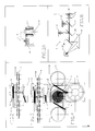
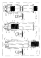
- FIG. 1 shows a schematic overall view of a device according to the invention
- 2 shows the lifting and guide elements in the raised state
- 3 the lifting and guiding elements in the lowered state
- 4 shows a top view of FIG. 2
- 5 to 7 a chip cylinder in different working positions
- FIG. 8 a schematic representation of the color recognition and reading head.
- the device according to the invention is arranged below a roulette table 1 indicated in outline, which is provided with a roulette wheel 2.
- a throw-in in table 1 Opening 3 into which the croupier simply drops all chips and tokens of various sizes to be sorted.
- the thrown-in chips fall into a drum 4 rotatable about a vertical axis, in which they are brought into a horizontal position.
- a plastic link chain 6 guided over gears 5 or driven by them drives the drum 4.
- the plastic chain 6 carries receiving plates for the chips removed from the drum 4, which receiving plates are explained in connection with FIGS. 2 to 4.
- a color recognition and reading head 7 After the drum 4 and then, but in the returning run a plurality of chip cylinders 8, in the example twelve chip cylinders are arranged along a curve adapted to the roulette wheel 2.
- the color recognition and reading head 7 controls compressed air cylinders which act on pivotable ramps 9, the mode of operation of which can be seen from FIGS. 2, 3 and 4.
- a ramp 9 and a fixed wiper 10 are assigned to each chip cylinder 8.
- Height-adjustable plungers 12 are mounted on the plastic link chain 6 in bushings 11 and are height-adjustable and carry the receiving plates 13 for the chips 14 at their upper end.
- the underside of the lifting plunger 12 is provided with a head 15 which interacts with the ramp 9.
- On the receiving plate 13, a rolling edge 16 is also arranged.
- FIG. 2A shows a variant for lifting the lifting plunger 12 together with the receiving plate 13, in which the lifting is effected by energizing an electromagnet instead of via a compressed air cylinder.
- the head 115 of the lifting plunger 12 is made of iron and instead of the ramp 17 a box profile 117 is provided which has a slot 119 at the top for the passage of the lifting plunger 12.
- One leg of the profile 117 is surrounded by a coil E which can be connected to a direct current source.
- the head 115 of the lifting plunger 12 which moves into the profile 117 in the position shown in broken lines, is lifted when the current flows through the coil E due to the electromagnetic effect, and the chip lying on the receiving plate, as in the exemplary embodiment according to FIGS of the scraper 10.
- This embodiment has the advantage that the ram 12 is raised without contact and without noise.
- FIG. 5 shows the state corresponding to FIGS. 2 and 4 in connection with the chip cylinder 8.
- Each chip cylinder has four mutually movable beams 18 and a lifter 19 actuated by a pneumatic cylinder.
- This lifter has a part 20 provided with a half-notch.
- a part 22 complementing the notch 21 is slidably mounted in the chip cylinder 8 and is under the action of springs 23 urging it upward.
- the bars 18 are provided with projections 24 which can snap into the notch 21.
- the lifter 19 In the state shown in Figure 5, the lifter 19 is in its lowermost position, the part 22 and thus the notch 21 are accordingly shifted downwards.
- the lugs 24 are pressed outwards by the part 20 and the bars 18 are accordingly also in their outer position.
- a predetermined number of chips in the chip cylinder 8 e.g. twenty pieces, is lifted by the pneumatic cylinder of the lifter 19 into the position shown in FIG. 6, in which the lugs 24 snap into the complete notch 21.
- the bars 18 move towards each other and the chips in the stack are centered.
- the chips are lifted through openings 25 onto the table 1, on the other hand, the springs 23 press the part 22 into its upper position, so that the lugs 24 and thus the wall parts 18 are pushed outwards.
- the sector-shaped flaps 26 partially closing the openings 25 close when the lifter 19 moves back and hold the chip stack in a vertical position. No chip is inserted into the corresponding chip cylinder either during the centering process (FIG. 6) or during the lifting and lowering process of the lifter 19 (FIG. 7).
- the Farberkenn- and read head 7, according to Figure 8, a light source 27 that illuminates at an angle of about 45 o to moving past chip fourteenth
- the image of the chip 14 is transmitted line by line to three CCD sensors 32, 33 and 34 via a deflection mirror 28 and filters 29, 30 and 31.
- the filter 29 is a reflection filter red
- the filter 30 is a reflection filter green
- the filter 31 is a pass filter blue.
- a separate evaluation of the colors red, green and blue is therefore possible.
- the analog color signals are converted into digital values of 0..255 by an 8 bit AD converter.
- the chip moves at a constant speed speed of 0.2 m / min. An evaluation is transferred to the electronics every 5 msec. This results in an electronic image of the chip with a resolution of 200x50 points.
- a microprocessor uses these digital values to determine the color, size and appearance of the chip. By comparison with the stored chip data, it is determined which chip cylinder 8 must be used for the recognized chip. A mechanical adjustment of the optics is not necessary because the chronological sequence of the measured value acquisition is derived from the sequence of movements of the chain. The three separate individual images can then be evaluated separately by the microprocessor.
- the device according to the invention is also able to sort chips and tokens of different sizes and colors. All ergonomic requirements from the croupier's point of view and the safety of the game are also met. If the electronic control fails, the chips or tokens cannot be damaged. The entire arrangement can also be built up mirror-inverted, which enables operation on left and right roulette tables.
Abstract
Description
Die Erfindung bezieht sich auf eine Vorrichtung zum Sortieren von Chips an Spieltischen, die unterhalb des Spieltisches angeordnet ist und die sortierten Chips in Stapeln für die Entnahme durch den Croupier bereitstellt.The invention relates to a device for sorting chips on gaming tables, which is arranged below the gaming table and provides the sorted chips in stacks for removal by the croupier.
Im Casinobetrieb ist es international üblich, bei den sogenannten Lebendspielen nicht mit Bargeld, sondern mit 'Jetons' od. 'Chips' seinen Spieleinsatz zu tätigen. Die Gewinne werden ebenfalls mit Chips ausbezahlt. Jeder Chip stellt einen bestimmten Wert dar und muß vor Spielbeginn gekauft werden. Die gewonnenen Chips können jederzeit wieder gegen Bargeld umgetauscht werden. Dadurch wird es jedem Gast ermöglicht zu spielen, egal ob er mit Dollars oder Schilling in ein Casino kommt. Außerdem hat der Spieler durch die Chips keine direkte Geld-Wertbeziehung und kann sich dadurch mehr auf das Spielen konzentrieren.In casino operations, it is common practice internationally to play with so-called live games, not with cash, but with 'tokens' or 'chips'. The winnings are also paid out with chips. Each chip represents a certain value and must be bought before the game starts. The chips won can be exchanged for cash at any time. This enables every guest to play, regardless of whether they come to a casino with dollars or shillings. In addition, the player has no direct money-value relationship due to the chips and can therefore concentrate more on playing.
Beim Roulettspielen gibt es zwei verschiedene Spieltischarten. Den französischen Tisch, auf dem nur mit sogenannten Wertchips gespielt wird (das sind Chips, die einen zahlenmäßigen Wert aufgedruckt haben) und den amerikanischen Tisch, auf dem mit Wertchips und 'CUTJETONS' gespielt wird. Cutjetons sind Chips, die keinen Wertaufdruck haben und sich durch unterschiedliche Farben unterscheiden. Kommt ein Spieler zu so einem Tisch, so kann er sich eine Jetonfarbe aussuchen und den Wert der Jetons selbst bestimmen. Wählt der Spieler die Farbe ROT und bewertet den Jeton mit 100, so wird die Farbe ROT exklusiv für diesen Spieler verwendet und der Preis der Jetons beträgt 100. Der Spieler tauscht nun seine Wertchips gegen die roten Jetons und kann damit auf diesem Tisch spielen. Durch dieses System kann der Spieler beliebig viele Spieleinsätze am Tisch tätigen ohne den Überblick zu verlieren, da ja alle roten Jetons ihm gehören. Bei jedem dieser Tische stehen sieben Farben für sieben Spieler zur Verfügung. Zusätzlich besteht auch noch die Möglichkeit, auf diesem Tisch mit Wertchips zu spielen. Ein weiterer Vorteil dieser Spielart ist es, daß die Spielfolge schnell und die Spannungsphasen zwischen Gewinn und Verlust häufig sind.There are two different types of table when playing roulette. The French table, on which only so-called value chips are played (these are chips that have a numerical value printed on them) and the American table, on which the chips and 'CUTJETONS' are played. Cutjetons are chips that have no value print and differ in different colors. If a player comes to such a table, he can choose a token color and determine the value of the tokens himself. If the player chooses the color RED and rates the chip with 100, the color RED is used exclusively for this player and the price of the tokens is 100. The player now swaps his tokens for the red tokens and can play on this table. This system allows the player to place as many bets on the table as they like without losing sight of the fact that all red chips are his. Each of these tables has seven colors for seven players. In addition, there is also the possibility to play with value chips on this table. Another advantage of this type of game is that the game sequence is fast and the tension phases between profit and loss are frequent.
Bisher wurden nach Spielende alle Chips und Jetons, die bei einem Spiel verloren wurden, durch den Croupier mit beiden Händen eingesammelt. Aus dem sogenannten 'SALAT' wurden dann die einzelnen Farben herausgesucht. Diese Tätigkeit ist zeitraubend und lenkt sowohl die Spieler als auch den Croupier vom eigentlichen Spiel ab.So far, after the game, all chips and tokens that were lost in a game were collected by the croupier with both hands. The individual colors were then selected from the so-called 'SALAT'. This activity is time consuming and distracts both the player and the croupier from the actual game.
Um dies zu vermeiden, wurde schon eine Sortiermaschine auf den Markt gebracht, die gleich große Jetons mit sieben unterschiedlichen Farben unterhalb des Tisches trennt und die Jetons in schrägen Ablagen für die Entnahme durch den Croupier bereitstellt. Der Einsatzbereich der bekannten Maschine ist jedoch beschränkt und die Bereitstellung in schrägen Ablagen hat sich nicht als günstig erwiesen.In order to avoid this, a sorting machine has already been brought onto the market that separates tokens of the same size with seven different colors below the table and makes the tokens available in inclined trays for removal by the croupier. However, the area of use of the known machine is limited and the provision in inclined storage has not proven to be favorable.
Die Erfindung hat es sich zum Ziel gesetzt, eine Vorrichtung der eingangs genannten Art zu schaffen, die die Nachteile der bekannten Vorrichtung nicht aufweist und insbesondere verschieden große Chips sortiert und in lotrechten Stapeln ablegt. Erreicht wird dies dadurch, daß unterhalb des Spieltisches ein in waagrechter Ebene umlaufender Endlosförderer mit höhenbeweglich angeordenten Aufnahmetellern für die über eine Einwurföffnung eingeworfenen Chips vorgesehen und in Bewegungsrichtung des Endlosförderers eine Einrichtung zum Verbringen der Chips in eine horizontale Lage, anschließend ein Farberkenn- und Lesekopf und daran anschließend eine Mehrzahl von Chipzylindern angeordnet ist, deren jeder einer vorgegebenen Chipart zugeordnet ist, wobei der Farberkenn- und Lesekopf Hub- und Leitorgane steuert, die einen Chip in den zugehörigen Chipzylinder heben und führen, und in jedem Chipzylinder ein Heber geführt ist, der bei Erreichen einer vorgegebenen Anzahl von Chips diese über dem Tisch in einem lotrechten Stapel ablegt.The invention has set itself the goal of creating a device of the type mentioned at the outset which does not have the disadvantages of the known device and in particular sorts chips of different sizes and stores them in vertical stacks. This is achieved in that below the gaming table a continuous conveyor in a horizontal plane with vertically movable receiving plates is provided for the chips thrown in via an insertion opening and in the direction of movement of the endless conveyor a device for moving the chips into a horizontal position, then a color recognition and reading head and about it a plurality of chip cylinders is then arranged, each of which is assigned to a predetermined type of chip, the color recognition and reading head controlling lifting and guiding elements which lift and guide a chip into the associated chip cylinder, and a lifter which is guided in each chip cylinder When a predetermined number of chips are reached, they are placed in a vertical stack above the table.
Ein insbesondere hinsichtlich des Antriebes einfacher Aufbau ergibt sich, wenn die Einrichtung zum Verbringen der Chips in eine horizontale Lage als eine um eine lotrechte Achse umlaufende Trommel ausgebildet ist, die vom Endlosförderer angetrieben ist.A simple construction, in particular with regard to the drive, is obtained if the device for moving the chips into a horizontal position is designed as a drum which rotates about a vertical axis and is driven by the endless conveyor.
Vorteilhaft ist der Endlosförderer als Kunststoff - Laschenkette ausgebildet und die Aufnahmeteller sind an Hubstössel befestigt, die an der Kette höhenbeweglich gelagert sind und deren Unterteil zum Zusammenwirken mit einer vom Farberkenn- und Lesekopf gesteuerten Auflauframpe, Nocke od.dgl. ausgebildet ist. Eine solche Vorrichtung weist einen lautlosen mechanischen Antrieb auf und es entstehen auch keine sich auf den Roulettkessel schädlich auswirkenden Vibrationen.The endless conveyor is advantageously designed as a plastic link chain and the receiving plates are attached to lifting plungers which are mounted on the chain so that they can move vertically and whose lower part is used to interact with a ramp, cam or the like controlled by the color recognition and reading head. is trained. Such a device has a silent mechanical drive and there are also no vibrations which have a detrimental effect on the roulette wheel.
Die Zuführung des Chips in den zugehörigen Chipzylinder erfolgt bei einer einfachen und sicheren Ausführungsform dadurch, daß jedem Chipzylinder ein feststehender Abstreifer zugeordnet ist, der oberhalb der Bewegungsbahn der Chips bei nicht gehobenem Aufnahmeteller und in der Bewegungsbahn der Chips bei gehobenem Aufnahmeteller liegt. Zweckmäßig weist dabei der Aufnahmeteller eine den Chip entlang des Abstreifers drückende Abrollkante auf.In a simple and safe embodiment, the chip is fed into the associated chip cylinder in that each chip cylinder is assigned a fixed scraper which lies above the path of movement of the chips when the receiving plate is not raised and in the path of the chips when the receiving plate is raised. The receiving plate expediently has a rolling edge that presses the chip along the scraper.
Bei einer bevorzugten Ausführungsform der Erfindung weist der Chipzylinder wenigstens zwei, vorzugsweise vier zueinander radial bewegliche Balken auf und die Bewegung der Balken zueinander wird in Abhängigkeit von einer vorgegebenen Anzahl von Chips im Chipzylinder gesteuert. Dadurch ist es möglich, in den Chipzylinder eingebrachte Chips, die einen kleineren Durchmesser als der Chipzylinder aufweisen, durch Bewegen der Balken zu zentrieren, um sie nach durchgeführtem Zentriervorgang als geschlossenen Stapel auf den Tisch zu heben.In a preferred embodiment of the invention, the chip cylinder has at least two, preferably four bars which are radially movable relative to one another and the movement of the bars relative to one another is controlled as a function of a predetermined number of chips in the chip cylinder. This makes it possible to insert chips into the chip cylinder, which have a smaller diameter than the chip cylinder, by moving the bars in order to lift them after the centering process as a closed stack on the table.
Eine Ausführungsform, bei der zum Zentrieren und zum Heben des Stapels nur ein Pneumatikzylinder erforderlich ist, zeichnet sich dadurch aus, daß der im Chipzylinder geführte, von einem Pneumatikzylinder betätigte Heber einen mit einer Halbkerbe versehenen Teil aufweist und ein die Kerbe ergänzender Teil unter der Wirkung einer ihn nach oben drängenden Federkraft steht, ferner die zueinander beweglichen Balken mit in die Kerbe einrastbaren Ansätzen versehen sind, wobei der unter Federkraft stehende Kerbenteil zwischen einer Lage unter den Ansätzen und einer Lage ober den Ansätzen bewegbar ist.An embodiment in which only one pneumatic cylinder is required for centering and lifting the stack is characterized in that the lifter guided in the chip cylinder and actuated by a pneumatic cylinder has a part provided with a half-notch and a part which complements the notch under the action a spring force pushing it upward, furthermore the mutually movable beams are provided with lugs that can be snapped into the notch, the spring-loaded notch part being movable between a position below the lugs and a position above the lugs.
Zweckmäßig weist der Farberkenn- und Lesekopf mehrere, vorzugsweise drei CCD-Sensoren auf, denen jeweils ein Farbfilter vorgeschaltet ist, und daß die analogen Farbsignale in digitale Werte umgesetzt sowie in einen Mikroprozessor übertragen werden, wobei der zeitliche Ablauf der Meßwerterfassung aus dem Bewegungsablauf de Kette abgeleitet wird. Der mechanische Aufbau des Farberkenn- und Lesekopfes muß daher mechanisch nicht justiert werden.The color detection and reading head expediently has several, preferably three, CCD sensors, each of which is preceded by a color filter, and that the analog color signals are converted into digital values and transmitted to a microprocessor, with the chronological sequence of the measured value acquisition from the movement sequence of the chain is derived. The mechanical structure of the color detection and reading head therefore does not have to be adjusted mechanically.
Nachstehend ist die Erfindung an Hand eines in den Zeichnungen dargestellten Ausführungsbeispieles näher beschrieben. Dabei zeigen: Fig.1 eine schematische Gesamtansicht einer erfindungsgemäßen Vorrichtung; Fig.2 die Hub- und Leitorgane im gehobenen Zustand; Fig.3 die Hub- und Leitorgane im abgesenkten Zustand; Fig.4 eine Draufsicht zu Fig.2; die Fig.5 bis 7 einen Chipzylinder in verschiedenen Arbeitsstellungen und Fig.8 eine schematische Darstellung des Farberkenn- und Lesekopfes.The invention is described in more detail below on the basis of an exemplary embodiment shown in the drawings. 1 shows a schematic overall view of a device according to the invention; 2 shows the lifting and guide elements in the raised state; 3 the lifting and guiding elements in the lowered state; 4 shows a top view of FIG. 2; 5 to 7 a chip cylinder in different working positions and FIG. 8 a schematic representation of the color recognition and reading head.
Gemäß Fig.1 ist die erfindungsgemäße Vorrichtung unterhalb eines in Umrissen angedeuteten Roulettisches 1 angeordnet, der mit einem Roulettkessel 2 versehen ist. Im Tisch 1 befindet sich eine Einwurf öffnung 3, in die der Croupier alle zu sortierenden Chips und Jetons verschiedener Größe einfach einwirft. Die eingeworfenen Chips fallen in eine um eine lotrechte Achse drehbare Trommel 4, in der sie in eine horizontale Lage gebracht werden. Eine über Zahnräder 5 geführte bzw. von diesen angetriebene Kunststoff - Laschenkette 6 treibt die Trommel 4 an.According to FIG. 1, the device according to the invention is arranged below a roulette table 1 indicated in outline, which is provided with a
Die Kunststoffkette 6 trägt Aufnahmeteller für die von der Trommel 4 entnommenen Chips, welche Aufnahmeteller im Zusammenhang mit den Fig.2 bis 4 erläutert werden. In Bewegungsrichtung der Kunststoffkette 6 liegt nach der Trommel 4 ein Farberkenn- und Lesekopf 7 und daran anschließend, aber im rücklaufenden Trum eine Mehrzahl von Chipzylindern 8, im Beispiel sind zwölf Chipzylinder entlang einer dem Roulettkessel 2 angepaßten Kurve angeordnet.The
Der Farberkenn- und Lesekopf 7 steuert Druckluftzylinder, die an schwenkbaren Rampen 9 angreifen, deren Wirkungsweise aus den Fig.2, 3 und 4 ersichtlich ist. Jedem Chipzylinder 8 ist eine Rampe 9 sowie ein feststehender Abstreifer 10 zugeordnet. An der Kunststoff - Laschenkette 6 sind in Buchsen 11 Hubstössel 12 höhenverstellbar gelagert, die an ihrem oberen Ende die Aufnahmeteller 13 für die Chips 14 tragen. Die Unterseite der Hubstössel 12 ist mit einem Kopf 15 versehen, der mit der Auflauframpe 9 zusammenwirkt. am Aufnahmeteller 13 ist überdies eine Abrollkante 16 angeordnet.The color recognition and
Hat der Farberkenn- und Lesekopf 7 einen Chip erkannt und der Mikroprozessor die entsprechende Zuordnung zu einem der Chipzylinder 8 getroffen, wird die entsprechende Auflauframpe 9 durch ihren Druckluftzylinder gehoben (Fig.2) und der Kopf 15 des ankommenden Hubstössels 12 wird durch die Auflauframpe 9 auf die anschließende feststehende Rampe 17 geführt. Dadurch gelangt der auf dem Aufnahmeteller 13 liegende Chip 14 in den Wirkungsbereich des feststehenden Abstreifers 10 und der Chip 14 wird unter Mitwirkung der Abrollkante 16 in den zugehörigen Chipzylinder 8 gedrückt. Dieser Bewegungsablauf ist in den Fig.2 und 4 veranschaulicht.If the color recognition and
Bei den nicht dem Chip entsprechenden Chipzylindern 8 erfolgt keine Betätigung der Auflauframpe 9 und der Chip 14 wird unterhalb des feststehenden Abstreifers 10 vorbeibewegt (Fig.3).In the case of the
In Fig.2A ist eine Variante für das Anheben des Hubstössels 12 samt dem Aufnahmeteller 13 gezeigt, bei der das Anheben statt über einen Druckluftzylinder durch Erregen eines Elektromagneten bewirkt wird. Bei dieser Ausführungsform besteht der Kopf 115 des Hubstössels 12 aus Eisen und statt der Rampe 17 ist ein Kastenprofil 117 vorgesehen, das oben einen Schlitz 119 für den Durchtritt des Hubstössels 12 aufweist. Ein Schenkel des Profiles 117 wird von einer an eine Gleichstromquelle anschließbaren Spule E umgeben.2A shows a variant for lifting the lifting plunger 12 together with the
Der in das Profil 117 in der strichliert eingezeichneten Stellung einfahrende Kopf 115 des Hubstössels 12 wird bei Stromfluß durch die Spule E zufolge der elektromagnetschen Wirkung angehoben und der auf dem Aufnahmeteller liegende Chip gelangt so wie beim Ausführungsbeispiel nach den Fig.2 und 3 in den Wirkungsbereich des Abstreifers 10.The
Diese Ausführungsform hat den Vorteil, daß das Anheben des Stössels 12 berührungslos und ohne Geräuschentwicklung erfolgt.This embodiment has the advantage that the
In Fig.5 ist der den Fig.2 und 4 entsprechende Zustand im Zusammenhang mit dem Chipzylinder 8 dargestellt. Jeder Chipzylinder besitzt vier zueinander bewegliche Balken 18 und einen von einem Pneumatikzylinder betätigten Heber 19. Dieser weist einen mit einer Halbkerbe versehenen Teil 20 auf. Ein die Kerbe 21 ergänzender Teil 22 ist im Chipzylinder 8 verschiebbar gelagert und steht unter der Wirkung von ihn nach oben drängenden Federn 23. Die Balken 18 sind mit Ansätzen 24 versehen, die in die Kerbe 21 einrasten können.5 shows the state corresponding to FIGS. 2 and 4 in connection with the
Bei dem in Fig.5 dargestellten Zustand ist der Heber 19 in seiner untersten Lage, der Teil 22 und damit die Kerbe 21 sind demnach nach unten verschoben. Die Ansätze 24 werden durch den Teil 20 nach außen gedrückt und die Balken 18 sind demnach ebenfalls in ihrer äußeren Lage. Die bei gehobener Auflauframpe 9 durch den Abstreifer 10 durch einen Schlitz in den Chipzylinder 8 eingeschobenen Chips 14 fallen auf den Heber 19, wobei, abhängig vom Durchmesser der Chips, eine mehr oder weniger unzentrierte Lage eingenommen wird. Bei Erreichen einer vorgegebenen Anzahl von Chips im Chipzylinder 8, z.B. zwanzig Stück, wird durch den Pneumatikzylinder der Heber 19 in die aus Fig.6 gezeichnete Lage gehoben, in der die Ansätze 24 in die vollständige Kerbe 21 einrasten. Die Balken 18 bewegen sich zueinander und die Chips im Stapel werden zentriert. Bei der anschließenden weiteren Hubbewegung des Hebers 19 werden einerseits die Chips durch Öffnungen 25 auf den Tisch 1 gehoben, anderseits drücken die Federn 23 den Teil 22 in seine obere Stellung, sodaß die Ansätze 24 und damit die Wandteile 18 nach außen gedrängt werden. Die die Öffnungen 25 teilweise verschließenden sektorförmigen Klappen 26 schließen sich beim Zurückfahren des Hebers 19 und halten den Chipstapel in lotrechter Stellung. Sowohl während de Zentriervorganges (Fig.6) als auch während des Hub- und Absenkvorganges des Hebers 19 (Fig.7) erfolgt kein Einführen eines Chips in den entsprechenden Chipzylinder.In the state shown in Figure 5, the
Der Farberkenn- und Lesekopf 7 weist gemäß Fig.8 eine Lichtquelle 27 auf, die in einem Winkel von etwa 45o den vorbeibewegten Chip 14 beleuchtet. Das Abbild des Chips 14 wird über einen Umlenkspiegel 28 und Filter 29, 30 und 31 zeilenweise auf drei CCD-Sensoren 32, 33 und 34 übertragen. Das Filter 29 ist ein Reflexionsfilter rot, das Filter 30 ein Reflexionsfilter grün und das Filter 31 ein Durchlaßfilter blau. Es ist somit eine getrennte Auswertung der Farben Rot, Grün und Blau möglich. Die analogen Farbsignale werden durch einen 8 Bit AD-Wandler in digitale Werte von 0..255 konvertiert. Der Chip bewegt sich mit einer konstanten Geschwindig keit von 0.2 m/min. Alle 5 msec wird eine Auswertung in die Elektronik übertragen. Dadurch kommt es zu einem elektonischen Abbild des Chips mit einer Auflösung von 200x50 Punkten. Aus diesen digitalen Werten bestimmt ein Microprozessor die Farbe, Größe und das Aussehen des Chips. Durch Vergleich mit den gespeicherten Chipdaten wird bestimmt, welcher Chipzylinder 8 für den erkannten Chip verwendet werden muß. Eine mechanische Justierung der Optik ist nicht erforderlich, da der zeitliche Ablauf der Messwerterfassung aus dem Bewegungsablauf der Kette abgeleitet wird. Die drei getrennten Einzelbilder können dann durch den Microprozessor getrennt ausgewertet werden.The Farberkenn- and read
Es hat sich gezeigt, daß bei Verwendung der erfindungsgemäßen Vorrichtung ein Geräusch für den Spieler nicht wahmehmbar ist. Dies zufolge des Einsatzes von Pneumatikzylindern und eines Schneckengetriebes für den Antrieb der Kunststoff - Laschenkette. Die erfindungsgemäße Vorrichtung ist ferner in der Lage, Chips und Jetons verschiedener Größe und Farbe zu sortieren. Es werden ferner alle ergonomischen Anforderungen aus dem Gesichtspunkt des Croupiers und der Spielsicherheit erfüllt. Bei einem Ausfall der elektronischen Steuerung kann es zu keiner Beschädigung der Chips bzw. Jetons kommen. Die gesamte Anordnung kann auch spiegelverkehrt aufgebaut werden, wodurch ein Betrieb an linken und rechten Roulettischen möglich ist.It has been shown that when using the device according to the invention, a sound is not perceptible to the player. This is due to the use of pneumatic cylinders and a worm gear for driving the plastic link chain. The device according to the invention is also able to sort chips and tokens of different sizes and colors. All ergonomic requirements from the croupier's point of view and the safety of the game are also met. If the electronic control fails, the chips or tokens cannot be damaged. The entire arrangement can also be built up mirror-inverted, which enables operation on left and right roulette tables.
Im Rahmen der Erfindung sind zahlreiche Abänderungen möglich. So ist die Verwendung einer erfindungsgemäßen Vorrichtung nicht unbedingt nur bei Roulettischen möglich, sie könnte vielmehr auch bei anderen Spieltischen eingesetzt werden.Numerous modifications are possible within the scope of the invention. Thus, the use of a device according to the invention is not only possible with roulette tables, but could also be used with other gaming tables.
Claims (9)
Applications Claiming Priority (2)
| Application Number | Priority Date | Filing Date | Title |
|---|---|---|---|
| AT0236689A AT401436B (en) | 1989-10-16 | 1989-10-16 | DEVICE FOR SORTING CHIPS ON PLAY TABLES |
| AT2366/89 | 1989-10-16 |
Publications (2)
| Publication Number | Publication Date |
|---|---|
| EP0424355A1 true EP0424355A1 (en) | 1991-04-24 |
| EP0424355B1 EP0424355B1 (en) | 1994-11-30 |
Family
ID=3533029
Family Applications (1)
| Application Number | Title | Priority Date | Filing Date |
|---|---|---|---|
| EP90890278A Expired - Lifetime EP0424355B1 (en) | 1989-10-16 | 1990-10-11 | Device for sorting chips at game-tables |
Country Status (6)
| Country | Link |
|---|---|
| EP (1) | EP0424355B1 (en) |
| AT (1) | AT401436B (en) |
| DE (1) | DE59007848D1 (en) |
| DK (1) | DK0424355T3 (en) |
| ES (1) | ES2066193T3 (en) |
| GR (1) | GR3015108T3 (en) |
Cited By (20)
| Publication number | Priority date | Publication date | Assignee | Title |
|---|---|---|---|---|
| GB2254419A (en) * | 1991-08-06 | 1992-10-07 | Amusement Equip Co Ltd | Sorting of differently identified gaming chips |
| WO1993018487A2 (en) * | 1992-03-11 | 1993-09-16 | Atoll Technology | Devices for sorting coins, tokens and the like and automatic pay machines |
| EP0631260A2 (en) * | 1993-06-22 | 1994-12-28 | Christian Pohanka | Device for centring chips on a stack |
| WO1996017329A2 (en) * | 1994-11-29 | 1996-06-06 | Etablissements Bourgogne Et Grasset | Gambling chip authentication device |
| WO1996023281A1 (en) * | 1995-01-24 | 1996-08-01 | Chipper 2000 (Isle Of Man) Limited | Colour detection apparatus |
| FR2739708A1 (en) * | 1995-10-09 | 1997-04-11 | Bourgogne Grasset | Authentication station for tokens of type used in casino for gaming |
| FR2752973A1 (en) * | 1996-09-05 | 1998-03-06 | Bourgogne Grasset | Electronic game token operation validation machine |
| US5895321A (en) * | 1995-10-09 | 1999-04-20 | Etablissements Bourgogne Et Grasset | Gambling chip |
| GB2333632A (en) * | 1998-01-23 | 1999-07-28 | Technical Casino Services Ltd | Disc sorting apparatus and method |
| US6581747B1 (en) | 2000-02-15 | 2003-06-24 | Etablissements Bourgogne Et Grasset | Token with an electronic chip and methods for manufacturing the same |
| US7681708B2 (en) | 2003-02-03 | 2010-03-23 | Shuffle Master Gmbh & Co Kg | Apparatus for sorting articles |
| US7861868B2 (en) | 2002-06-05 | 2011-01-04 | Shuffle Master Gmbh & Co Kg | Chip sorting and stacking devices |
| US7883408B2 (en) | 2003-05-12 | 2011-02-08 | Gaming Partners International | Station for reading and/or writing in electronic gaming chips |
| US7918455B2 (en) | 2005-11-09 | 2011-04-05 | Gaming Partners International | Chip with insert including an electronic microchip |
| US7934980B2 (en) | 2002-06-05 | 2011-05-03 | Shuffle Master Gmbh & Co Kg | Chip stack cutter devices for displacing chips in a chip stack and chip-stacking apparatuses including such cutter devices |
| WO2011051700A1 (en) * | 2009-11-02 | 2011-05-05 | Shuffle Master Gmbh & Co Kg. | Chip sorting devices, components therefor and methods of ejecting chips |
| GB2560098A (en) * | 2017-01-10 | 2018-08-29 | Gamtec International Ltd | Gaming tables |
| US10096192B1 (en) * | 2017-08-30 | 2018-10-09 | Shuffle Master Gmbh & Co Kg | Chip sorting devices and related assemblies and methods |
| EP3599593A1 (en) * | 2018-07-23 | 2020-01-29 | Gamtec International Limited | Gaming tables for roulette and similar games |
| US10621816B2 (en) | 2018-07-24 | 2020-04-14 | Gametec International Limited | Gaming tables for roulette and similar games |
Families Citing this family (3)
| Publication number | Priority date | Publication date | Assignee | Title |
|---|---|---|---|---|
| FR2888372B1 (en) | 2005-07-08 | 2007-10-12 | Caming Partners Internationale | ELECTRONIC CHIP TOKEN AND METHOD OF MANUFACTURING THE SAME |
| CA2614291C (en) | 2007-05-25 | 2015-02-17 | Gaming Partners International | Token with electronic device |
| US9836909B2 (en) | 2016-04-06 | 2017-12-05 | Shuffle Master Gmbh & Co Kg | Chip sorting devices and related assemblies, components and methods |
Citations (3)
| Publication number | Priority date | Publication date | Assignee | Title |
|---|---|---|---|---|
| AT169894B (en) * | 1949-11-04 | 1951-12-27 | Gustav Dipl Ing Chlestil | Roulette table |
| FR1003486A (en) * | 1947-01-10 | 1952-03-18 | Improvements made to gaming, roulette and thirty and forty tables | |
| AT380814B (en) * | 1984-09-10 | 1986-07-10 | Andritz Ag Maschf | SORTING DEVICE FOR SEPARATING RANDOM DISTRIBUTIONS BY COLOR, BRIGHTNESS VALUE, LARGE OR THE SAME DIFFERENT PARTICLES |
-
1989
- 1989-10-16 AT AT0236689A patent/AT401436B/en not_active IP Right Cessation
-
1990
- 1990-10-11 ES ES90890278T patent/ES2066193T3/en not_active Expired - Lifetime
- 1990-10-11 EP EP90890278A patent/EP0424355B1/en not_active Expired - Lifetime
- 1990-10-11 DE DE59007848T patent/DE59007848D1/en not_active Expired - Fee Related
- 1990-10-11 DK DK90890278.6T patent/DK0424355T3/en active
-
1995
- 1995-02-17 GR GR950400333T patent/GR3015108T3/en unknown
Patent Citations (3)
| Publication number | Priority date | Publication date | Assignee | Title |
|---|---|---|---|---|
| FR1003486A (en) * | 1947-01-10 | 1952-03-18 | Improvements made to gaming, roulette and thirty and forty tables | |
| AT169894B (en) * | 1949-11-04 | 1951-12-27 | Gustav Dipl Ing Chlestil | Roulette table |
| AT380814B (en) * | 1984-09-10 | 1986-07-10 | Andritz Ag Maschf | SORTING DEVICE FOR SEPARATING RANDOM DISTRIBUTIONS BY COLOR, BRIGHTNESS VALUE, LARGE OR THE SAME DIFFERENT PARTICLES |
Cited By (32)
| Publication number | Priority date | Publication date | Assignee | Title |
|---|---|---|---|---|
| GB2254419B (en) * | 1991-08-06 | 1995-08-02 | Amusement Equip Co Ltd | Sorting of differently identified articles |
| GB2254419A (en) * | 1991-08-06 | 1992-10-07 | Amusement Equip Co Ltd | Sorting of differently identified gaming chips |
| EP0731427A3 (en) * | 1992-03-11 | 1998-09-30 | Atoll Technology | Method for recognizing objects such as coins |
| WO1993018487A2 (en) * | 1992-03-11 | 1993-09-16 | Atoll Technology | Devices for sorting coins, tokens and the like and automatic pay machines |
| WO1993018487A3 (en) * | 1992-03-11 | 1994-02-17 | Atoll Technology | Devices for sorting coins, tokens and the like and automatic pay machines |
| EP0731427A2 (en) * | 1992-03-11 | 1996-09-11 | Atoll Technology | Method for recognizing objects such as coins |
| EP0631260A2 (en) * | 1993-06-22 | 1994-12-28 | Christian Pohanka | Device for centring chips on a stack |
| EP0631260A3 (en) * | 1993-06-22 | 1995-01-11 | Christian Pohanka | Device for centring chips on a stack |
| AT400003B (en) * | 1993-06-22 | 1995-09-25 | Pohanka Christian Ing | DEVICE FOR SORTING CHIPS ON PLAY TABLES |
| WO1996017329A2 (en) * | 1994-11-29 | 1996-06-06 | Etablissements Bourgogne Et Grasset | Gambling chip authentication device |
| WO1996017329A3 (en) * | 1994-11-29 | 1996-08-29 | Bourgogne Grasset | Gambling chip authentication device |
| WO1996023281A1 (en) * | 1995-01-24 | 1996-08-01 | Chipper 2000 (Isle Of Man) Limited | Colour detection apparatus |
| AU700096B2 (en) * | 1995-01-24 | 1998-12-24 | Technical Casino Services Limited | Colour detection apparatus |
| FR2739708A1 (en) * | 1995-10-09 | 1997-04-11 | Bourgogne Grasset | Authentication station for tokens of type used in casino for gaming |
| US5895321A (en) * | 1995-10-09 | 1999-04-20 | Etablissements Bourgogne Et Grasset | Gambling chip |
| FR2752973A1 (en) * | 1996-09-05 | 1998-03-06 | Bourgogne Grasset | Electronic game token operation validation machine |
| GB2333632A (en) * | 1998-01-23 | 1999-07-28 | Technical Casino Services Ltd | Disc sorting apparatus and method |
| US6581747B1 (en) | 2000-02-15 | 2003-06-24 | Etablissements Bourgogne Et Grasset | Token with an electronic chip and methods for manufacturing the same |
| US8006847B2 (en) | 2002-06-05 | 2011-08-30 | Shuffle Master Gmbh & Co Kg | Chip sorting device |
| US7861868B2 (en) | 2002-06-05 | 2011-01-04 | Shuffle Master Gmbh & Co Kg | Chip sorting and stacking devices |
| US7934980B2 (en) | 2002-06-05 | 2011-05-03 | Shuffle Master Gmbh & Co Kg | Chip stack cutter devices for displacing chips in a chip stack and chip-stacking apparatuses including such cutter devices |
| US7992720B2 (en) | 2002-06-05 | 2011-08-09 | Shuffle Master Gmbh & Co Kg | Chip sorting device |
| US7681708B2 (en) | 2003-02-03 | 2010-03-23 | Shuffle Master Gmbh & Co Kg | Apparatus for sorting articles |
| US7883408B2 (en) | 2003-05-12 | 2011-02-08 | Gaming Partners International | Station for reading and/or writing in electronic gaming chips |
| US7918455B2 (en) | 2005-11-09 | 2011-04-05 | Gaming Partners International | Chip with insert including an electronic microchip |
| WO2011051700A1 (en) * | 2009-11-02 | 2011-05-05 | Shuffle Master Gmbh & Co Kg. | Chip sorting devices, components therefor and methods of ejecting chips |
| US9536367B2 (en) | 2009-11-02 | 2017-01-03 | Shuffle Master Gmbh & Co Kg | Chip handling devices and related methods |
| GB2560098A (en) * | 2017-01-10 | 2018-08-29 | Gamtec International Ltd | Gaming tables |
| GB2560098B (en) * | 2017-01-10 | 2020-10-07 | Gamtec International Ltd | Gaming tables |
| US10096192B1 (en) * | 2017-08-30 | 2018-10-09 | Shuffle Master Gmbh & Co Kg | Chip sorting devices and related assemblies and methods |
| EP3599593A1 (en) * | 2018-07-23 | 2020-01-29 | Gamtec International Limited | Gaming tables for roulette and similar games |
| US10621816B2 (en) | 2018-07-24 | 2020-04-14 | Gametec International Limited | Gaming tables for roulette and similar games |
Also Published As
| Publication number | Publication date |
|---|---|
| EP0424355B1 (en) | 1994-11-30 |
| ATA236689A (en) | 1996-01-15 |
| DK0424355T3 (en) | 1995-05-01 |
| DE59007848D1 (en) | 1995-01-12 |
| ES2066193T3 (en) | 1995-03-01 |
| GR3015108T3 (en) | 1995-05-31 |
| AT401436B (en) | 1996-09-25 |
Similar Documents
| Publication | Publication Date | Title |
|---|---|---|
| EP0424355B1 (en) | Device for sorting chips at game-tables | |
| DE4401655C2 (en) | Game element for a perforated ball game | |
| DE3248291C2 (en) | Slot machine | |
| DE4320927A1 (en) | Multi-level game component for a pinball game | |
| DE19633658A1 (en) | Ball racket for a pinball game | |
| DE3702965C2 (en) | ||
| DE291230C (en) | ||
| AT6405U1 (en) | CHIP SORTING DEVICE | |
| DE3811301C2 (en) | ||
| DE2902716B2 (en) | Device for sorting and counting coins with sorting track and counting lever | |
| DE2146646A1 (en) | Vibrating bowl for feeding buttons | |
| DE3218189A1 (en) | DEVICE FOR REMOVING AND DEPOSITING AREA PARTS, IN PARTICULAR TEXTILE PARTS | |
| EP0631260B1 (en) | Device for centring chips on a stack | |
| DE1109089B (en) | Sorting device with upwardly pivoting conveyor track sections | |
| DE3410901C2 (en) | ||
| DE4414025C2 (en) | Pinball game with an inclined pitch | |
| DE3802253A1 (en) | COIN ACTUATED ENTERTAINMENT MACHINE | |
| DE2644500C3 (en) | Device for feeding cartridge sleeves or other hollow workpieces closed at one end, in a certain orientation | |
| DE3705327C2 (en) | ||
| EP0124653A1 (en) | Device for depositing textile tubes on a conveyor belt | |
| DE4309642A1 (en) | Transfer device for workpiece transport | |
| DE19634688B4 (en) | Device for processing chip cards | |
| DE19631368A1 (en) | Automated device for testing printed circuit boards | |
| DE2803894C3 (en) | Coin operated gaming machine | |
| DE60310163T2 (en) | System for conveying and lifting coins in a slot machine with profitability |
Legal Events
| Date | Code | Title | Description |
|---|---|---|---|
| PUAI | Public reference made under article 153(3) epc to a published international application that has entered the european phase |
Free format text: ORIGINAL CODE: 0009012 |
|
| 17P | Request for examination filed |
Effective date: 19901228 |
|
| AK | Designated contracting states |
Kind code of ref document: A1 Designated state(s): BE CH DE DK ES FR GB GR IT LI LU NL SE |
|
| 17Q | First examination report despatched |
Effective date: 19931229 |
|
| GRAA | (expected) grant |
Free format text: ORIGINAL CODE: 0009210 |
|
| AK | Designated contracting states |
Kind code of ref document: B1 Designated state(s): BE CH DE DK ES FR GB GR IT LI LU NL SE |
|
| REF | Corresponds to: |
Ref document number: 59007848 Country of ref document: DE Date of ref document: 19950112 |
|
| ITF | It: translation for a ep patent filed |
Owner name: ING. A. GIAMBROCONO & C. S.R.L. |
|
| GBT | Gb: translation of ep patent filed (gb section 77(6)(a)/1977) |
Effective date: 19950125 |
|
| REG | Reference to a national code |
Ref country code: ES Ref legal event code: FG2A Ref document number: 2066193 Country of ref document: ES Kind code of ref document: T3 |
|
| ET | Fr: translation filed | ||
| REG | Reference to a national code |
Ref country code: GR Ref legal event code: FG4A Free format text: 3015108 |
|
| REG | Reference to a national code |
Ref country code: DK Ref legal event code: T3 |
|
| PLBE | No opposition filed within time limit |
Free format text: ORIGINAL CODE: 0009261 |
|
| STAA | Information on the status of an ep patent application or granted ep patent |
Free format text: STATUS: NO OPPOSITION FILED WITHIN TIME LIMIT |
|
| 26N | No opposition filed | ||
| PGFP | Annual fee paid to national office [announced via postgrant information from national office to epo] |
Ref country code: BE Payment date: 20000831 Year of fee payment: 11 |
|
| PGFP | Annual fee paid to national office [announced via postgrant information from national office to epo] |
Ref country code: CH Payment date: 20000901 Year of fee payment: 11 |
|
| PGFP | Annual fee paid to national office [announced via postgrant information from national office to epo] |
Ref country code: ES Payment date: 20000905 Year of fee payment: 11 |
|
| PGFP | Annual fee paid to national office [announced via postgrant information from national office to epo] |
Ref country code: SE Payment date: 20000906 Year of fee payment: 11 |
|
| PGFP | Annual fee paid to national office [announced via postgrant information from national office to epo] |
Ref country code: FR Payment date: 20000911 Year of fee payment: 11 |
|
| PGFP | Annual fee paid to national office [announced via postgrant information from national office to epo] |
Ref country code: LU Payment date: 20000921 Year of fee payment: 11 |
|
| PGFP | Annual fee paid to national office [announced via postgrant information from national office to epo] |
Ref country code: GB Payment date: 20000928 Year of fee payment: 11 |
|
| PGFP | Annual fee paid to national office [announced via postgrant information from national office to epo] |
Ref country code: GR Payment date: 20000929 Year of fee payment: 11 |
|
| PGFP | Annual fee paid to national office [announced via postgrant information from national office to epo] |
Ref country code: DK Payment date: 20001012 Year of fee payment: 11 |
|
| PGFP | Annual fee paid to national office [announced via postgrant information from national office to epo] |
Ref country code: NL Payment date: 20001031 Year of fee payment: 11 |
|
| PG25 | Lapsed in a contracting state [announced via postgrant information from national office to epo] |
Ref country code: LU Free format text: LAPSE BECAUSE OF NON-PAYMENT OF DUE FEES Effective date: 20011011 Ref country code: GB Free format text: LAPSE BECAUSE OF NON-PAYMENT OF DUE FEES Effective date: 20011011 Ref country code: DK Free format text: LAPSE BECAUSE OF NON-PAYMENT OF DUE FEES Effective date: 20011011 |
|
| PG25 | Lapsed in a contracting state [announced via postgrant information from national office to epo] |
Ref country code: SE Free format text: LAPSE BECAUSE OF NON-PAYMENT OF DUE FEES Effective date: 20011012 Ref country code: ES Free format text: LAPSE BECAUSE OF NON-PAYMENT OF DUE FEES Effective date: 20011012 |
|
| PG25 | Lapsed in a contracting state [announced via postgrant information from national office to epo] |
Ref country code: LI Free format text: LAPSE BECAUSE OF NON-PAYMENT OF DUE FEES Effective date: 20011031 Ref country code: GR Free format text: LAPSE BECAUSE OF NON-PAYMENT OF DUE FEES Effective date: 20011031 Ref country code: CH Free format text: LAPSE BECAUSE OF NON-PAYMENT OF DUE FEES Effective date: 20011031 Ref country code: BE Free format text: LAPSE BECAUSE OF NON-PAYMENT OF DUE FEES Effective date: 20011031 |
|
| REG | Reference to a national code |
Ref country code: GB Ref legal event code: IF02 |
|
| BERE | Be: lapsed |
Owner name: POHANKA CHRISTIAN Effective date: 20011031 |
|
| PG25 | Lapsed in a contracting state [announced via postgrant information from national office to epo] |
Ref country code: NL Free format text: LAPSE BECAUSE OF NON-PAYMENT OF DUE FEES Effective date: 20020501 |
|
| GBPC | Gb: european patent ceased through non-payment of renewal fee |
Effective date: 20011011 |
|
| EUG | Se: european patent has lapsed |
Ref document number: 90890278.6 |
|
| REG | Reference to a national code |
Ref country code: CH Ref legal event code: PL |
|
| REG | Reference to a national code |
Ref country code: DK Ref legal event code: EBP |
|
| PG25 | Lapsed in a contracting state [announced via postgrant information from national office to epo] |
Ref country code: FR Free format text: LAPSE BECAUSE OF NON-PAYMENT OF DUE FEES Effective date: 20020628 |
|
| NLV4 | Nl: lapsed or anulled due to non-payment of the annual fee |
Effective date: 20020501 |
|
| REG | Reference to a national code |
Ref country code: FR Ref legal event code: ST |
|
| REG | Reference to a national code |
Ref country code: ES Ref legal event code: FD2A Effective date: 20021113 |
|
| PGFP | Annual fee paid to national office [announced via postgrant information from national office to epo] |
Ref country code: DE Payment date: 20050816 Year of fee payment: 16 |
|
| PG25 | Lapsed in a contracting state [announced via postgrant information from national office to epo] |
Ref country code: IT Free format text: LAPSE BECAUSE OF NON-PAYMENT OF DUE FEES;WARNING: LAPSES OF ITALIAN PATENTS WITH EFFECTIVE DATE BEFORE 2007 MAY HAVE OCCURRED AT ANY TIME BEFORE 2007. THE CORRECT EFFECTIVE DATE MAY BE DIFFERENT FROM THE ONE RECORDED. Effective date: 20051011 |
|
| PG25 | Lapsed in a contracting state [announced via postgrant information from national office to epo] |
Ref country code: DE Free format text: LAPSE BECAUSE OF NON-PAYMENT OF DUE FEES Effective date: 20070501 |