EP0425286A2 - A dishwasher - Google Patents
A dishwasher Download PDFInfo
- Publication number
- EP0425286A2 EP0425286A2 EP19900311699 EP90311699A EP0425286A2 EP 0425286 A2 EP0425286 A2 EP 0425286A2 EP 19900311699 EP19900311699 EP 19900311699 EP 90311699 A EP90311699 A EP 90311699A EP 0425286 A2 EP0425286 A2 EP 0425286A2
- Authority
- EP
- European Patent Office
- Prior art keywords
- drain
- dishwasher
- liquid
- sink
- rinse aid
- Prior art date
- Legal status (The legal status is an assumption and is not a legal conclusion. Google has not performed a legal analysis and makes no representation as to the accuracy of the status listed.)
- Withdrawn
Links
Images


Classifications
-
- A—HUMAN NECESSITIES
- A47—FURNITURE; DOMESTIC ARTICLES OR APPLIANCES; COFFEE MILLS; SPICE MILLS; SUCTION CLEANERS IN GENERAL
- A47L—DOMESTIC WASHING OR CLEANING; SUCTION CLEANERS IN GENERAL
- A47L15/00—Washing or rinsing machines for crockery or tableware
- A47L15/0086—In-sink dishwashers
-
- A—HUMAN NECESSITIES
- A47—FURNITURE; DOMESTIC ARTICLES OR APPLIANCES; COFFEE MILLS; SPICE MILLS; SUCTION CLEANERS IN GENERAL
- A47L—DOMESTIC WASHING OR CLEANING; SUCTION CLEANERS IN GENERAL
- A47L15/00—Washing or rinsing machines for crockery or tableware
- A47L15/14—Washing or rinsing machines for crockery or tableware with stationary crockery baskets and spraying devices within the cleaning chamber
- A47L15/18—Washing or rinsing machines for crockery or tableware with stationary crockery baskets and spraying devices within the cleaning chamber with movably-mounted spraying devices
- A47L15/22—Rotary spraying devices
- A47L15/23—Rotary spraying devices moved by means of the sprays
-
- A—HUMAN NECESSITIES
- A47—FURNITURE; DOMESTIC ARTICLES OR APPLIANCES; COFFEE MILLS; SPICE MILLS; SUCTION CLEANERS IN GENERAL
- A47L—DOMESTIC WASHING OR CLEANING; SUCTION CLEANERS IN GENERAL
- A47L15/00—Washing or rinsing machines for crockery or tableware
- A47L15/42—Details
- A47L15/44—Devices for adding cleaning agents; Devices for dispensing cleaning agents, rinsing aids or deodorants
Definitions
- the present invention relates to dishwashers and, in particular to sink mounted dishwashers in which the sink bowl constitutes the receptacle into which the dirty dishes and utensils are placed in order to be washed.
- a sink mounted dishwasher comprising a sink having a base and side walls, a drain located in said base, a spray arm removably and rotatably mounted in said sink and rotatable by water directed into said spray arm by a pump connected to said drain wherein a drain closure member is mounted in said drain below the pump connection and is operable between a drain closed configuration in which water in said sink can be circulated by said pump through said spray arm, and a drain open configuration in which water in said sink is drained through said drain closure member.
- a hydraulic control system for a dishwasher having an hydraulically operated liquid detergent dispenser and an hydraulically operated drain closure member, said system comprising a reservoir for liquid rinse aid, a pump having an inlet connected to said reservoir and an outlet connected to three solenoid valves, a first one of said solenoid valves communicating said rinse aid to said detergent dispenser to hydraulically control the operation of same, a second one of said solenoid valves communicating said rinse aid to said drain closure member to hydraulically control the operation of same, and the third one of said solenoid valves connecting said rinse aid to said dishwasher to dispense same.
- the rinse aid is dispensed into the outlet of the liquid detergent dispenser.
- a spray arm mounting arrangement for a dishwasher mounted in a sink having a drain comprising a substantially cylindrical hollow body dimensioned to be insertable into said drain, a collar substantially co-axial with said cylindrical body and located at one, upper, end thereof by a plurality of supporting webs, said collar supporting said spray arm, a hollow elbow interconnecting said collar with an opening in the side wall of said body communicable with a pump outlet, said elbow communicating said pump outlet with a hollow interior of said spray arm via said collar without obstructing liquid draining from said sink between said webs and through said hollow body.
- the spray arm has an upper and a lower tier and water passing through said collar is directed into both said tiers via a dual co-axial poppet valve seated within said collar.
- part of said body is perforated and comprises a filter leading to a pump inlet whereby any residue remaining on said filter near the end of each dishwasher cycle is washed from said filter as water is drained from the sink.
- a dispenser for easily dried liquids such as dishwasher liquid detergent
- said dispenser being located in a water supply line and comprising a liquid tight housing divided into two compartments by a diaphram, one of said compartments having an inlet and an outlet for connection to said water supply line, and a connection to a source of said liquid closed by a poppet valve having a stem extending into said one compartment and secured to said diaphram, biasing means to urge said diaphram away from said connection to thereby maintain said poppet valve normally closed, and the other of said compartments being connectable to a source of hydraulic fluid to pressurize said other compartment and move said diaphram against the urging of said biasing means to thereby open said poppet valve and dispense said liquid into said supply line via said one compartment.
- the preferred hydraulic fluid is rinse aid liquid.
- a drain closure member for a dishwasher mounted in a sink having a drain said member comprising a hollow torroid of elastically deformable sheet material having its outer surface sealingly secured to the inner surface of said drain, the interior of said torroid being connected to a source of hydraulic fluid, said torrid when not pressurised by said fluid having an aperture therethrough through which liquid in said drain can pass, and said torroid when pressurized by said fluid expanding to constrict said aperture and substantially prevent the passage of liquid therethrough.
- the preferred hydraulic fluid is rinse aid liquid.
- a drain closure member for a dishwasher mounted in a sink having a drain said member comprising a cap mounted for longitudinal reciprocal movement along said drain into and out of an enlarged drain portion, the diameter of said cap corresponding to that of said drain whereby said drain is open only when said cap is in said enlarged portion.
- the preferred form of dishwasher in accordance with the present invention is mounted in the larger bowl 1 of a two bowl sink 2 having a centrally located tap or faucet 3 and a control panel 4.
- a tap or faucet 3 mounted alongside the tap 3 are two releasably sealable openings 5,6 which are respectively used to re-fill rinse aid and detergent into respective containers (not illustrated in Fig. 1) mounted below the level of the sink 2.
- the bowl 1 is provided with a removable cover 7 which is supported by hinge mountings 8,9.
- the hinge mounting 9 is used to provide a concealed entry for liquid into the bowl 1 at a level which is above the maximum possible level of water within the bowl 1. In this way, contamination of the supply line leading to the bowl 1 and/or the mains supply by the bowl contents is avoided.
- a spray arm assembly 10 and a basket 11 for dishes and utensils are located within the bowl.
- the sink 2 is preferably provided with a thick layer of insulation 12 (illustrated on one side only for clarity) in order to minimize the loss of heat through the thermally conductive stainless steel bowl 1.
- a pump 13 mounted above the outer body of the drain closure member 14 below which extends the drain 15 and the connector 16 by which the drain 15 is connected to an S-trap 17 (Fig. 6).
- the housing 18 has an outlet 68 connected to the inlet of the pump 13.
- the outlet of the pump 13 is returned via pipe 24 to the interior of the housing 18.
- Two solenoids 19 and 67 are used to selectively connect a water supply line 58 which leads ultimately to the bowl 1 to either a hot water supply or a cold water supply (not illustrated).
- the detail of the spray arm assembly 10 and its support are illustrated in Fig. 3.
- the hollow body 20 is provided with a collar 21 which is co-axially mounted at the upper end of the hollow body 20 by means of a number of generally radially extending webs 22 which together with the collar 21 form a spider.
- the hollow body 20 is provided with an opening 23 in its side wall which is connected to the outlet of the pump 13 by a pipe 24 (Figs. 2 and 6). As illustrated in Fig. 4, the collar 21 is also connected to the opening 23 by means of a hollow elbow 25.
- the spray arm assembly 10 takes the form of a central cross-shaped member 26 having a downwardly directed spigot 27 which is rotatably mounted in the collar 21.
- each of four lower spray arms 28 each of which has jets 29 and an upwardly directed spray slot 30.
- the lower spray arms 28 are clamped in position by means of a cross-shaped clamp 31 which clamps the arms 28 against the central member 26.
- the spray arm assembly 10 is completed by means of an upper spray arm 32.
- Fig. 4 illustrates in schematic form how water is introduced into both the upper spray arm 32 and the four lower spray arms 28. It will be seen that located within the spigot 27 is a two-part poppet valve mechanism 33.
- the valve mechanism 33 takes the form of an outer valve ring 34 and an inner valve stem 35. The position in the absence of water flow is illustrated on the left hand side of Fig. 4. Here both the outer valve ring 34 and the inner valve stem 35 are in their lower, rest positions with the valve ring 34 abutting the inner surface of the spigot 27 and the head 36 of the valve stem 35 abutting the inner surface of the valve ring 34.
- the position when water is supplied from the pump via opening 23 is illustrated on the right hand side of Fig. 4.
- the force of the water raises the outer valve ring 34 so that it allows water to pass upwardly and into the lower spray arms 28.
- the outer valve ring 34 is profiled so as to direct only a predetermined portion of the total flow into the lower spray arms 28.
- the force of the water entering via opening 23 also lifts the valve stem 35 so that its head 36 no longer occludes the central opening in the outer valve ring 34. As a result, some of the water is able to pass between the valve stem 35 and valve ring 34 where it is led upwardly towards, and into, the upper spray arm 32.
- valve stem 35 is provided with a boss 37 which limits the upward travel of the valve stem 35. This limit is provided by a sleeve 38 co-axially mounted within the spigot 27 by means of support webs 39.
- a hollow torroid 41 formed from sheet material such as polyurethane which is elastically deformable.
- a source of hydraulic fluid which, as will be described hereafter in relation to Fig. 6, preferably takes the form of liquid rinse aid.
- the outer surfaces of the torroid 41 are connected to the drain closure member 14, for example by means of sealing compound.
- the torroid 41 has a negligible radial extent and therefore allows passage of material through its central aperture 44 and into the drain 15. Accordingly, in this configuration, the torroid 41 allows unobstructed access to the drain 15.
- the hollow body 20 is illustrated in Fig. 4 is provided with a portion of its side wall formed as a perforated metal sheet which functions as a filter 66. With the torroid 41 expanded to block the drain 15, water can be pumped from the interior of the hollow body 20, through the filter 66, and out the outlet 68 to the pump 13. This water can then be returned via pipe 24 and opening 23 to the spray arms 28,32 and thence to the bowl 1.
- the hydraulic control system for the dishwasher will now be described with reference to Fig. 6.
- the liquid detergent is a suspension of soap particles in a liquid and is highly viscous. In addition, the suspension is prone to settling and drying out. It therefore tends to clog conventional dispensers if left unused for any period of time.
- the detergent container 46 is directly mounted on a dispenser 47 which is illustrated in more detail in Fig. 7.
- the rinse aid container 45 is connected via a rinse aid pump 48 to a rinse aid inlet 49 on the dispenser 47.
- the dispenser 47 is also provided with a rinse aid outlet 50, a drain connector outlet 51, a water outlet 52 and water inlet 53. Also provided are solenoids 54 and 55. A further solenoid 56 is located in the line 57 connecting the drain connector outlet 51 to the torroid 41 within the drain closure member 14. A water inlet line 58 connects hot water to the water inlet 53 whilst the water outlet 52 is connected to the hinge mounting 9 by means of a water outlet line 59. A rinse aid line 60 connects the rinse aid outlet 50 to the water outlet 52.
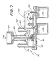
- Fig. 7 The interior detail of the dispenser 47 is illustrated in Fig. 7.
- the view of the dispenser 47 in Fig. 7 is from the opposite side of that illustrated in Fig. 6. It will be seen that the water outlet 52 and water inlet 53 communicate with a chamber 61 divided into upper and lower portions by a diaphragm 62. Supported by the diaphragm 62 is a valve stem 63 which in its rest position illustrated in Fig. 7 closes a valve seat 64 which is directly connected to the detergent container 46 as illustrated in Fig. 6. The valve stem 63 is maintained in its closed rest position illustrated in Fig. 7 by means of a spring 65.
- the rinse aid inlet 49 is directly connected to the drain connector outlet 51. Also the rinse aid inlet 49 is connected via solenoids 54 and 55 respectively to the rinse aid outlet 50 and the lower portion of the chamber 61. As also seen in Fig. 7, the rinse aid line 60 connecting the rinse aid outlet 50 with the water outlet 52 does so by means of an orifice 65 in the water outlet 52.
- the operation of the control system illustrated in Fig. 6 is as follows. Firstly, the rinse aid pump 48 is operated so as to fill the line 57 and the lower portion of chamber 61 with rinse aid. Any bubbles are removed by bleeding to enable the rinse aid to operate effectively as an hydraulic fluid.
- the solenoid 56 is operated so as to close the drain closure member 14. Then the sink is filled to its operating level with hot water under the control of solenoid 19 (Fig. 2). When the appropriate level of hot water in the bowl 1 is reached, solenoid 19 is de-energized to stop the filling action.
- the the pump 13 is operated so as to draw water already in the bowl 1 from the interior of the hollow body 20 through the filter 66, through the pump 13 where it is returned to the opening 23 and passes into the spray arms 28,32. This action is continued for 30 seconds in order to wash any larger dirt and grime particles from the dishes and utensils contained in the bowl 1.
- the solenoid 56 is then re-energized in order to close the drain closure member 14, and the bowl 1 is again filled with hot water.
- the solenoid 55 is energized so as to dispense detergent into the hot water during the filling of the bowl 1.
- a wash cycle of 4 minutes duration then follows during which the hot water containing detergent located within the bowl is cycled by the pump 13 through the spray arms 28,32.
- the solenoid 56 is again de-energized so as to allow this water to be dumped into the drain 15.
- the bowl 1 is then again filled with hot water following re-energization of the solenoid 56, however, during this filling operation the solenoid 54 is energized so as to dispense rinse aid into the hot water. A washing cycle of approximately 2 minutes duration is then undertaken with the water containing rinse aid. At the end of this period, the solenoid 56 is again de-energized thereby dumping the water containing rinse aid into the drain 15.
- the final portion of the normal cycle is to allow the dishes and utensils contained in the basket 11 to dry by absorbing heat which is retained by the metal bowl 1. This provides a satisfactory arrangement provided that the cover 7 is vented so as to allow water vapour to escape into the atmosphere.
- the total cycle time for the normal cycle is approximately 121/2 minutes.
- Variations to the normal cycle can be provided as follows.
- a "rinse cycle” in which only the first stage of washing grime from the dishes and utensils is carried out, a “heavy duty cycle” in which the 4 minute wash is repeated, and a “glass cycle” in which the initial rinse is with cold water (supplied via solenoid 67) rather than hot water to prevent the dry glasses being subjected to thermal shock which may shatter them.
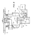
- FIG. 8 an alternative embodiment of the spray arm arrangement and an alternative embodiment of the drain closure member are illustrated.
- the housing 18 and drain 15 are substantially as before, however, only a pair of opposed spray arms 128 are provided in a single tier.
- the arms 128 are rotatably mounted on a hollow plastics turret 127.
- the turret 127 is in turn releasably secured to a central collar 121 which is supported by webs 22 as before.
- the collar 121 is supplied with water from the pump by means of the hollow elbow 25 as before.
- the spray arms 128 are removable from the sink 2 by dis-engagement of the turret 127 from the collar 121.
- the arrangement of the hollow body 20 is substantially as before save that a dome-shaped cap 140 is provided to enable the drain 15 to be opened or closed.
- the cap 140 is mounted on a shaft 141 which is slidably located in a sleeve 142 supported by radial webs 143.
- the lower end of the shaft 141 is pivotally connected to an L-shaped lever 144 which protrudes through an opening 145 in the drain 15.
- the opening 145 is sealed by means of a flexible rubber boot 146.
- the level 144 is connected to the armature 147 of a solenoid 148 by means of a latching mechanical linkage 149.
- a heater can be provided to heat the water supplied to the bowl 1 should it not be sufficiently hot. Typically this means a temperature of approximately 60°C.
- the preferred form of cover 7 is a sandwich formed from two layers of plastic with insulating foam in between.
- the cover 7 is further preferably provided with a smooth downwardly facing concave surface which enables water to drain to the periphery of the cover and therefore prevents drops of water falling from the cover 7 onto the dried dishes at the conclusion of the cycle.
Abstract
Description
- The present invention relates to dishwashers and, in particular to sink mounted dishwashers in which the sink bowl constitutes the receptacle into which the dirty dishes and utensils are placed in order to be washed.
- Such dishwashers are known and that disclosed in Australian Patent Application No. 78927/87 (which corresponds to U.S. Patent No. 4,919,162) by the same applicant represents a starting point for the present invention. The present invention arises out of further refinement and development of the abovementioned prior art.
- Accordingly, it is an object of the present invention to improve various aspects of the abovementioned prior art dishwasher and, in particular, to improve the closure mechanism by which the drain of the sink is blocked during a washing cycle, to provide a control system for the dishwasher, to improve the mounting of the spray rm, and to dispense liquid dishwasher detergent which suffers from the problem that it tends to clog conventional dispensers if the dishwasher is left unoperated as would be the case when the occupants of a household are absent during an annual vacation, for example. All these aspects or facets combine to produce a much improved dishwasher which is disclosed herein.
- According to a first aspect of the present invention there is disclosed a sink mounted dishwasher comprising a sink having a base and side walls, a drain located in said base, a spray arm removably and rotatably mounted in said sink and rotatable by water directed into said spray arm by a pump connected to said drain wherein a drain closure member is mounted in said drain below the pump connection and is operable between a drain closed configuration in which water in said sink can be circulated by said pump through said spray arm, and a drain open configuration in which water in said sink is drained through said drain closure member.
- According to a second aspect of the present invention there is disclosed a hydraulic control system for a dishwasher having an hydraulically operated liquid detergent dispenser and an hydraulically operated drain closure member, said system comprising a reservoir for liquid rinse aid, a pump having an inlet connected to said reservoir and an outlet connected to three solenoid valves, a first one of said solenoid valves communicating said rinse aid to said detergent dispenser to hydraulically control the operation of same, a second one of said solenoid valves communicating said rinse aid to said drain closure member to hydraulically control the operation of same, and the third one of said solenoid valves connecting said rinse aid to said dishwasher to dispense same. Preferably the rinse aid is dispensed into the outlet of the liquid detergent dispenser.
- According to a third aspect of the present invention there is disclosed a spray arm mounting arrangement for a dishwasher mounted in a sink having a drain, said arrangement comprising a substantially cylindrical hollow body dimensioned to be insertable into said drain, a collar substantially co-axial with said cylindrical body and located at one, upper, end thereof by a plurality of suporting webs, said collar supporting said spray arm, a hollow elbow interconnecting said collar with an opening in the side wall of said body communicable with a pump outlet, said elbow communicating said pump outlet with a hollow interior of said spray arm via said collar without obstructing liquid draining from said sink between said webs and through said hollow body. Preferably the spray arm has an upper and a lower tier and water passing through said collar is directed into both said tiers via a dual co-axial poppet valve seated within said collar. Preferably part of said body is perforated and comprises a filter leading to a pump inlet whereby any residue remaining on said filter near the end of each dishwasher cycle is washed from said filter as water is drained from the sink.
- According to a fourth aspect of the present invention there is disclosed a dispenser for easily dried liquids such as dishwasher liquid detergent, said dispenser being located in a water supply line and comprising a liquid tight housing divided into two compartments by a diaphram, one of said compartments having an inlet and an outlet for connection to said water supply line, and a connection to a source of said liquid closed by a poppet valve having a stem extending into said one compartment and secured to said diaphram, biasing means to urge said diaphram away from said connection to thereby maintain said poppet valve normally closed, and the other of said compartments being connectable to a source of hydraulic fluid to pressurize said other compartment and move said diaphram against the urging of said biasing means to thereby open said poppet valve and dispense said liquid into said supply line via said one compartment. Although either a gas or a liquid can be used for the hydraulic fluid, the preferred hydraulic fluid is rinse aid liquid.
- According to a fifth aspect of the present invention there is disclosed a drain closure member for a dishwasher mounted in a sink having a drain, said member comprising a hollow torroid of elastically deformable sheet material having its outer surface sealingly secured to the inner surface of said drain, the interior of said torroid being connected to a source of hydraulic fluid, said torrid when not pressurised by said fluid having an aperture therethrough through which liquid in said drain can pass, and said torroid when pressurized by said fluid expanding to constrict said aperture and substantially prevent the passage of liquid therethrough. Although either a gas or a liquid can be used as the hydraulic fluid, the preferred hydraulic fluid is rinse aid liquid.
- According to a sixth aspect of the present invention there is disclosed a drain closure member for a dishwasher mounted in a sink having a drain, said member comprising a cap mounted for longitudinal reciprocal movement along said drain into and out of an enlarged drain portion, the diameter of said cap corresponding to that of said drain whereby said drain is open only when said cap is in said enlarged portion.
- An embodiment of the present invention will now be described with reference to the drawings in which:
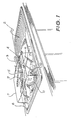
- Fig. 1 is a perspective view from above of the sink mounted dishwasher,
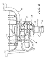
- Fig. 2 is a side elevational view of the apparatus located beneath the sink and of the spray arm arrangement, the sink itself being illustrated in vertical cross-section,
- Fig. 3 is an exploded perspective view of the spray arm mounting arrangement and hollow drain body,
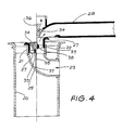
- Fig. 4 is a vertical cross-sectional view through the body and spray arm of Fig. 3.
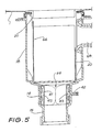
- Fig. 5 is a schematic vertical cross-sectional through the drain closure member which is located below the drain body illustrated in Fig. 3,
- Fig. 6 is a schematic block diagram of the hydraulic control system used in the dishwasher.
- Fig. 7 is a vertical cross-sectional view through the liquid dishwasher detergent dispenser included in the control system of Fig. 6, and
- Fig. 8 is a longitudinal sectional view through the base of the sink illustrating an alternative spray arm arrangement and alternative drain closure member.
- As seen in Fig. 1, the preferred form of dishwasher in accordance with the present invention is mounted in the larger bowl 1 of a two
bowl sink 2 having a centrally located tap orfaucet 3 and acontrol panel 4. Mounted alongside thetap 3 are two releasablysealable openings sink 2. - It will be seen that the bowl 1 is provided with a removable cover 7 which is supported by
hinge mountings hinge mounting 9 is used to provide a concealed entry for liquid into the bowl 1 at a level which is above the maximum possible level of water within the bowl 1. In this way, contamination of the supply line leading to the bowl 1 and/or the mains supply by the bowl contents is avoided. Also located within the bowl is aspray arm assembly 10 and abasket 11 for dishes and utensils. - Turning now to Fig. 2, it will be seen that the
sink 2 is preferably provided with a thick layer of insulation 12 (illustrated on one side only for clarity) in order to minimize the loss of heat through the thermally conductive stainless steel bowl 1. Also located below the level of thesink 2 is apump 13 mounted above the outer body of thedrain closure member 14 below which extends thedrain 15 and theconnector 16 by which thedrain 15 is connected to an S-trap 17 (Fig. 6). Between thedrain closure member 14 and the base of the bowl 1 is a generallycylindrical housing 18. Thehousing 18 has anoutlet 68 connected to the inlet of thepump 13. In addition, the outlet of thepump 13 is returned viapipe 24 to the interior of thehousing 18. Twosolenoids water supply line 58 which leads ultimately to the bowl 1 to either a hot water supply or a cold water supply (not illustrated). - The detail of the
spray arm assembly 10 and its support (in the form of hollow body 20) are illustrated in Fig. 3. Thehollow body 20 is provided with acollar 21 which is co-axially mounted at the upper end of thehollow body 20 by means of a number of generally radially extendingwebs 22 which together with thecollar 21 form a spider. Thehollow body 20 is provided with an opening 23 in its side wall which is connected to the outlet of thepump 13 by a pipe 24 (Figs. 2 and 6). As illustrated in Fig. 4, thecollar 21 is also connected to the opening 23 by means of ahollow elbow 25. - As illustrated in Fig. 3, the
spray arm assembly 10 takes the form of acentral cross-shaped member 26 having a downwardly directedspigot 27 which is rotatably mounted in thecollar 21. Connected to thecentral member 26 is each of fourlower spray arms 28 each of which hasjets 29 and an upwardly directedspray slot 30. Thelower spray arms 28 are clamped in position by means of across-shaped clamp 31 which clamps thearms 28 against thecentral member 26. Thespray arm assembly 10 is completed by means of anupper spray arm 32. - Fig. 4 illustrates in schematic form how water is introduced into both the
upper spray arm 32 and the fourlower spray arms 28. It will be seen that located within thespigot 27 is a two-part poppet valve mechanism 33. The valve mechanism 33 takes the form of anouter valve ring 34 and aninner valve stem 35. The position in the absence of water flow is illustrated on the left hand side of Fig. 4. Here both theouter valve ring 34 and theinner valve stem 35 are in their lower, rest positions with thevalve ring 34 abutting the inner surface of thespigot 27 and thehead 36 of thevalve stem 35 abutting the inner surface of thevalve ring 34. - The position when water is supplied from the pump via
opening 23 is illustrated on the right hand side of Fig. 4. Here, the force of the water raises theouter valve ring 34 so that it allows water to pass upwardly and into thelower spray arms 28. In addition, theouter valve ring 34 is profiled so as to direct only a predetermined portion of the total flow into thelower spray arms 28. The force of the water entering viaopening 23 also lifts thevalve stem 35 so that itshead 36 no longer occludes the central opening in theouter valve ring 34. As a result, some of the water is able to pass between thevalve stem 35 andvalve ring 34 where it is led upwardly towards, and into, theupper spray arm 32. In this connection, it will be appreciated that the lower end of thevalve stem 35 is provided with aboss 37 which limits the upward travel of thevalve stem 35. This limit is provided by asleeve 38 co-axially mounted within thespigot 27 by means ofsupport webs 39. - The interior detail of the
drain closure member 14 andcylindrical housing 18 is illustrated in Fig. 5. Located within thedrain closure member 14 is ahollow torroid 41 formed from sheet material such as polyurethane which is elastically deformable. By means of aninlet 42, theinterior 43 of thetorroid 41 is able to be connected to a source of hydraulic fluid which, as will be described hereafter in relation to Fig. 6, preferably takes the form of liquid rinse aid. The outer surfaces of thetorroid 41 are connected to thedrain closure member 14, for example by means of sealing compound. - As a consequence, in the uninflated condition illustrated by solid lines in Fig. 5, the
torroid 41 has a negligible radial extent and therefore allows passage of material through itscentral aperture 44 and into thedrain 15. Accordingly, in this configuration, thetorroid 41 allows unobstructed access to thedrain 15. - However, when the
interior 43 of thetorroid 41 is pressurized, the inner surfaces of thetorroid 41 expand towards each other so as to adopt the configuration illustrated by broken lines in Fig. 5 in which theaperture 44 is constricted to the point of elimination. As a result, liquid located above thetorroid 41 is prevented from gaining access to thedrain 15. - The
hollow body 20 is illustrated in Fig. 4 is provided with a portion of its side wall formed as a perforated metal sheet which functions as afilter 66. With thetorroid 41 expanded to block thedrain 15, water can be pumped from the interior of thehollow body 20, through thefilter 66, and out theoutlet 68 to thepump 13. This water can then be returned viapipe 24 andopening 23 to thespray arms - It will be apparent to those skilled in the art that any material which is deposited on the
filter 66 can be washed into thedrain 15 on the next occasion when thedrain closure member 14 is opened whilst there is water in the bowl 1. - The hydraulic control system for the dishwasher will now be described with reference to Fig. 6. Located beneath the
openings containers detergent container 46 is directly mounted on adispenser 47 which is illustrated in more detail in Fig. 7. The rinseaid container 45 is connected via a rinseaid pump 48 to a rinseaid inlet 49 on thedispenser 47. - The
dispenser 47 is also provided with a rinseaid outlet 50, adrain connector outlet 51, awater outlet 52 andwater inlet 53. Also provided aresolenoids further solenoid 56 is located in theline 57 connecting thedrain connector outlet 51 to thetorroid 41 within thedrain closure member 14. Awater inlet line 58 connects hot water to thewater inlet 53 whilst thewater outlet 52 is connected to the hinge mounting 9 by means of awater outlet line 59. A rinseaid line 60 connects the rinseaid outlet 50 to thewater outlet 52. - The interior detail of the
dispenser 47 is illustrated in Fig. 7. The view of thedispenser 47 in Fig. 7 is from the opposite side of that illustrated in Fig. 6. It will be seen that thewater outlet 52 andwater inlet 53 communicate with achamber 61 divided into upper and lower portions by adiaphragm 62. Supported by thediaphragm 62 is avalve stem 63 which in its rest position illustrated in Fig. 7 closes avalve seat 64 which is directly connected to thedetergent container 46 as illustrated in Fig. 6. The valve stem 63 is maintained in its closed rest position illustrated in Fig. 7 by means of aspring 65. - It will also be seen in Fig. 7 that the rinse
aid inlet 49 is directly connected to thedrain connector outlet 51. Also the rinseaid inlet 49 is connected viasolenoids aid outlet 50 and the lower portion of thechamber 61. As also seen in Fig. 7, the rinseaid line 60 connecting the rinseaid outlet 50 with thewater outlet 52 does so by means of anorifice 65 in thewater outlet 52. - It will be apparent from a consideration of Figs. 6 and 7 that when rinse aid is supplied under pressure from the rinse
aid pump 48, operation ofsolenoid 55 supplies pressurized rinse aid to the lower portion of thechamber 61 thereby moving thediaphragm 62 upwardly so as to raise thevalve stem 63 and allow detergent to be dispensed into the upper portion of thechamber 61. This detergent is entrapped in water flowing fromwater inlet 53 to thewater outlet 52. When thesolenoid 55 is no longer operated, thediaphragm 62 returns to its rest position illustrated in Fig. 7 thereby lowering thevalve stem 63 and preventing further flow of liquid detergent. However, thevalve stem 63 and the lower portions of thevalve seat 64 continue to be washed by water passing from thewater inlet 53 towater outlet 52 thereby ensuring that the liquid dishwasher detergent dispensing valve remains clean and therefore cannot become clogged with dried detergent. - The operation of the control system illustrated in Fig. 6 is as follows. Firstly, the rinse
aid pump 48 is operated so as to fill theline 57 and the lower portion ofchamber 61 with rinse aid. Any bubbles are removed by bleeding to enable the rinse aid to operate effectively as an hydraulic fluid. - After the "normal" cycle has been selected on the control panel 4 (Fig. 1), the
solenoid 56 is operated so as to close thedrain closure member 14. Then the sink is filled to its operating level with hot water under the control of solenoid 19 (Fig. 2). When the appropriate level of hot water in the bowl 1 is reached,solenoid 19 is de-energized to stop the filling action. The thepump 13 is operated so as to draw water already in the bowl 1 from the interior of thehollow body 20 through thefilter 66, through thepump 13 where it is returned to theopening 23 and passes into thespray arms - Then the
solenoid 56 is de-energized thereby allowing thetorroid 41 to return to its normal size which dumps the contents of the bowl 1 into thedrain 15. - The
solenoid 56 is then re-energized in order to close thedrain closure member 14, and the bowl 1 is again filled with hot water. However, on this occasion thesolenoid 55 is energized so as to dispense detergent into the hot water during the filling of the bowl 1. A wash cycle of 4 minutes duration then follows during which the hot water containing detergent located within the bowl is cycled by thepump 13 through thespray arms solenoid 56 is again de-energized so as to allow this water to be dumped into thedrain 15. - The bowl 1 is then again filled with hot water following re-energization of the
solenoid 56, however, during this filling operation thesolenoid 54 is energized so as to dispense rinse aid into the hot water. A washing cycle of approximately 2 minutes duration is then undertaken with the water containing rinse aid. At the end of this period, thesolenoid 56 is again de-energized thereby dumping the water containing rinse aid into thedrain 15. - The final portion of the normal cycle is to allow the dishes and utensils contained in the
basket 11 to dry by absorbing heat which is retained by the metal bowl 1. This provides a satisfactory arrangement provided that the cover 7 is vented so as to allow water vapour to escape into the atmosphere. The total cycle time for the normal cycle is approximately 12¹/₂ minutes. - Variations to the normal cycle can be provided as follows. A "rinse cycle" in which only the first stage of washing grime from the dishes and utensils is carried out, a "heavy duty cycle" in which the 4 minute wash is repeated, and a "glass cycle" in which the initial rinse is with cold water (supplied via solenoid 67) rather than hot water to prevent the dry glasses being subjected to thermal shock which may shatter them.
- Turning now to Fig. 8, an alternative embodiment of the spray arm arrangement and an alternative embodiment of the drain closure member are illustrated.
- The
housing 18 and drain 15 are substantially as before, however, only a pair of opposedspray arms 128 are provided in a single tier. Thearms 128 are rotatably mounted on ahollow plastics turret 127. Theturret 127 is in turn releasably secured to acentral collar 121 which is supported bywebs 22 as before. Thecollar 121 is supplied with water from the pump by means of thehollow elbow 25 as before. Thespray arms 128 are removable from thesink 2 by dis-engagement of theturret 127 from thecollar 121. - The arrangement of the
hollow body 20 is substantially as before save that a dome-shapedcap 140 is provided to enable thedrain 15 to be opened or closed. Thecap 140 is mounted on ashaft 141 which is slidably located in asleeve 142 supported byradial webs 143. The lower end of theshaft 141 is pivotally connected to an L-shapedlever 144 which protrudes through anopening 145 in thedrain 15. - The
opening 145 is sealed by means of aflexible rubber boot 146. Thelevel 144 is connected to thearmature 147 of asolenoid 148 by means of a latchingmechanical linkage 149. - It will be apparent that operation of the
solenoid 148 enables thelever 144 to raise or lower thecap 140. Since the diameter of thecap 140 matches the internal diameter of thedrain 15, in the lowered position thecap 140 closes thedrain 15 whilst in the raised position (as illustrated) thedrain 15 is open. - The foregoing describes only some embodiments of the present invention and modifications, obvious to those skilled in the art, can be made thereto without departing from the scope of the present invention. For example, a heater can be provided to heat the water supplied to the bowl 1 should it not be sufficiently hot. Typically this means a temperature of approximately 60°C. The preferred form of cover 7 is a sandwich formed from two layers of plastic with insulating foam in between. The cover 7 is further preferably provided with a smooth downwardly facing concave surface which enables water to drain to the periphery of the cover and therefore prevents drops of water falling from the cover 7 onto the dried dishes at the conclusion of the cycle.
Claims (17)
Applications Claiming Priority (2)
| Application Number | Priority Date | Filing Date | Title |
|---|---|---|---|
| AU7058/89 | 1989-10-25 | ||
| AUPJ705889 | 1989-10-25 |
Publications (2)
| Publication Number | Publication Date |
|---|---|
| EP0425286A2 true EP0425286A2 (en) | 1991-05-02 |
| EP0425286A3 EP0425286A3 (en) | 1991-07-24 |
Family
ID=3774307
Family Applications (1)
| Application Number | Title | Priority Date | Filing Date |
|---|---|---|---|
| EP19900311699 Withdrawn EP0425286A3 (en) | 1989-10-25 | 1990-10-25 | A dishwasher |
Country Status (6)
| Country | Link |
|---|---|
| US (1) | US5193562A (en) |
| EP (1) | EP0425286A3 (en) |
| JP (1) | JPH03207326A (en) |
| AU (1) | AU624744B2 (en) |
| CA (1) | CA2028400A1 (en) |
| NZ (1) | NZ235803A (en) |
Cited By (6)
| Publication number | Priority date | Publication date | Assignee | Title |
|---|---|---|---|---|
| GB2348117A (en) * | 1999-01-19 | 2000-09-27 | Procter & Gamble | Sink apparatus for providing cleaning benefits by self agitation |
| EP1062904A1 (en) * | 1999-06-21 | 2000-12-27 | The Procter & Gamble Company | In-sink micro-machine |
| EP1358833A2 (en) * | 2002-05-03 | 2003-11-05 | Whirlpool Corporation | Fill control system for an in-sink dishwasher |
| EP1358834A2 (en) * | 2002-05-03 | 2003-11-05 | Whirlpool Corporation | In-sink dishwasher with self-aligning liquid feed system |
| KR101069136B1 (en) | 2009-12-04 | 2011-09-30 | 송세진 | Sink attachment type dish washing apparatus |
| EP3354184A1 (en) * | 2017-01-26 | 2018-08-01 | LG Electronics Inc. | In-sink lokated dishwasher |
Families Citing this family (19)
| Publication number | Priority date | Publication date | Assignee | Title |
|---|---|---|---|---|
| US5934298A (en) * | 1997-11-14 | 1999-08-10 | Singh; Baljit | Combination sink and dishwasher |
| WO1999008810A1 (en) * | 1997-08-16 | 1999-02-25 | Baljit Singh | Combination sink and dishwasher |
| US5915851A (en) * | 1997-10-02 | 1999-06-29 | Whirlpool Corporation | Water dispensing and draining appliance |
| US6799085B1 (en) | 2000-06-08 | 2004-09-28 | Beverage Works, Inc. | Appliance supply distribution, dispensing and use system method |
| US7754025B1 (en) | 2000-06-08 | 2010-07-13 | Beverage Works, Inc. | Dishwasher having a door supply housing which holds dish washing supply for multiple wash cycles |
| US7083071B1 (en) | 2000-06-08 | 2006-08-01 | Beverage Works, Inc. | Drink supply canister for beverage dispensing apparatus |
| US7201175B2 (en) * | 2002-05-03 | 2007-04-10 | Whirlpool Corporation | User interface for an in-sink dishwasher |
| DE102007049061A1 (en) * | 2007-10-12 | 2009-04-16 | BSH Bosch und Siemens Hausgeräte GmbH | Method and device for cleaning a component, in particular an evaporator of a condenser device, and laundry or tumble dryer with such a device |
| KR100985384B1 (en) * | 2008-06-27 | 2010-10-05 | 주식회사 경동네트웍 | Method for controlling a hot water temperature in using low flux in hot water supply system |
| US8333207B2 (en) * | 2008-09-04 | 2012-12-18 | Jackson Msc Llc | Spray arm for directing spray in a warewashing machine |
| EP2431223B1 (en) | 2010-09-17 | 2012-11-07 | C.R.F. Società Consortile per Azioni | Equipped living compartment for transport vehicles |
| US9277849B2 (en) | 2010-11-02 | 2016-03-08 | Ecolab Usa Inc. | Combination dishwashing machine and sink |
| US9603501B2 (en) | 2011-09-02 | 2017-03-28 | Ecolab Usa Inc. | Use of recycled wash and rinse water for the pre-rinse operation of dishes |
| CN105534443A (en) * | 2016-01-22 | 2016-05-04 | 宁波欧琳厨具有限公司 | Water tank structure for water tank type cleaning equipment |
| CN105534444A (en) * | 2016-01-22 | 2016-05-04 | 宁波欧琳厨具有限公司 | Circulation cleaning system of sink type cleaning equipment |
| CN107616772B (en) * | 2016-07-14 | 2021-04-09 | 青岛海尔洗碗机有限公司 | Washing and dish washing powder adding device of dish washing machine |
| CN110664348B (en) * | 2018-07-02 | 2022-06-21 | 青岛海尔洗碗机有限公司 | Dish washing machine |
| CN112137542A (en) * | 2019-06-27 | 2020-12-29 | 青岛海尔洗碗机有限公司 | Dish washing machine and control method |
| US11844481B2 (en) | 2021-02-09 | 2023-12-19 | William Welling | Integrated dishwasher sink apparatus |
Citations (7)
| Publication number | Priority date | Publication date | Assignee | Title |
|---|---|---|---|---|
| US2669240A (en) * | 1945-10-17 | 1954-02-16 | Milton Z Thorson | Dish cleaning sink |
| US2681658A (en) * | 1949-10-11 | 1954-06-22 | Hobart Mfg Co | Dishwasher |
| US2965112A (en) * | 1956-12-28 | 1960-12-20 | Waste King Corp | Dishwasher pump and outlet valve |
| US3358702A (en) * | 1965-05-21 | 1967-12-19 | Schaap Theodore | Combination disposal and washer |
| US3415276A (en) * | 1966-12-16 | 1968-12-10 | Whirlpool Co | Fluid control system |
| CH473575A (en) * | 1967-05-02 | 1969-06-15 | Geyer Josef | Dish washing device |
| EP0262932A2 (en) * | 1986-09-29 | 1988-04-06 | McILWRAITH DAVEY PTY. LTD. | Sink located dishwashers |
Family Cites Families (5)
| Publication number | Priority date | Publication date | Assignee | Title |
|---|---|---|---|---|
| US1819355A (en) * | 1926-07-06 | 1931-08-18 | Kohler Co | Start and stop switch for combination dishwasher and sink |
| US2701574A (en) * | 1953-05-01 | 1955-02-08 | Apex Electrical Mfg Co | Dishwasher or the like |
| US3863657A (en) * | 1973-05-23 | 1975-02-04 | Willard Irving | Dishwasher and sink combination |
| US4420005A (en) * | 1982-11-01 | 1983-12-13 | Daniel Armstrong | Water powered dishwasher |
| AU597110B2 (en) * | 1986-09-29 | 1990-05-24 | McIlwraith-Davey Pty. Limited | A dishwasher |
-
1990
- 1990-10-24 NZ NZ235803A patent/NZ235803A/en unknown
- 1990-10-24 CA CA002028400A patent/CA2028400A1/en not_active Abandoned
- 1990-10-24 AU AU64980/90A patent/AU624744B2/en not_active Ceased
- 1990-10-25 US US07/604,478 patent/US5193562A/en not_active Expired - Fee Related
- 1990-10-25 JP JP2286040A patent/JPH03207326A/en active Pending
- 1990-10-25 EP EP19900311699 patent/EP0425286A3/en not_active Withdrawn
Patent Citations (7)
| Publication number | Priority date | Publication date | Assignee | Title |
|---|---|---|---|---|
| US2669240A (en) * | 1945-10-17 | 1954-02-16 | Milton Z Thorson | Dish cleaning sink |
| US2681658A (en) * | 1949-10-11 | 1954-06-22 | Hobart Mfg Co | Dishwasher |
| US2965112A (en) * | 1956-12-28 | 1960-12-20 | Waste King Corp | Dishwasher pump and outlet valve |
| US3358702A (en) * | 1965-05-21 | 1967-12-19 | Schaap Theodore | Combination disposal and washer |
| US3415276A (en) * | 1966-12-16 | 1968-12-10 | Whirlpool Co | Fluid control system |
| CH473575A (en) * | 1967-05-02 | 1969-06-15 | Geyer Josef | Dish washing device |
| EP0262932A2 (en) * | 1986-09-29 | 1988-04-06 | McILWRAITH DAVEY PTY. LTD. | Sink located dishwashers |
Cited By (12)
| Publication number | Priority date | Publication date | Assignee | Title |
|---|---|---|---|---|
| GB2348117A (en) * | 1999-01-19 | 2000-09-27 | Procter & Gamble | Sink apparatus for providing cleaning benefits by self agitation |
| EP1062904A1 (en) * | 1999-06-21 | 2000-12-27 | The Procter & Gamble Company | In-sink micro-machine |
| WO2000078200A2 (en) * | 1999-06-21 | 2000-12-28 | The Procter & Gamble Company | In-sink micro-machine |
| WO2000078200A3 (en) * | 1999-06-21 | 2001-07-05 | Procter & Gamble | In-sink micro-machine |
| EP1358833A2 (en) * | 2002-05-03 | 2003-11-05 | Whirlpool Corporation | Fill control system for an in-sink dishwasher |
| EP1358834A2 (en) * | 2002-05-03 | 2003-11-05 | Whirlpool Corporation | In-sink dishwasher with self-aligning liquid feed system |
| EP1358834A3 (en) * | 2002-05-03 | 2005-08-10 | Whirlpool Corporation | In-sink dishwasher with self-aligning liquid feed system |
| EP1358833A3 (en) * | 2002-05-03 | 2005-10-12 | Whirlpool Corporation | Fill control system for an in-sink dishwasher |
| KR101069136B1 (en) | 2009-12-04 | 2011-09-30 | 송세진 | Sink attachment type dish washing apparatus |
| EP3354184A1 (en) * | 2017-01-26 | 2018-08-01 | LG Electronics Inc. | In-sink lokated dishwasher |
| US10441076B2 (en) | 2017-01-26 | 2019-10-15 | Lg Electronics Inc. | Sink |
| US11266234B2 (en) | 2017-01-26 | 2022-03-08 | Lg Electronics Inc. | Sink |
Also Published As
| Publication number | Publication date |
|---|---|
| US5193562A (en) | 1993-03-16 |
| AU624744B2 (en) | 1992-06-18 |
| CA2028400A1 (en) | 1991-04-26 |
| JPH03207326A (en) | 1991-09-10 |
| AU6498090A (en) | 1991-05-02 |
| EP0425286A3 (en) | 1991-07-24 |
| NZ235803A (en) | 1993-03-26 |
Similar Documents
| Publication | Publication Date | Title |
|---|---|---|
| US5193562A (en) | Dishwasher | |
| KR100871069B1 (en) | Sink | |
| CA1270311A (en) | Low energy, low water consumption warewasher and method | |
| US9265398B2 (en) | Dishwasher with separate sump for concentrated fluid supply | |
| EP0262932B1 (en) | Sink located dishwashers | |
| US3370597A (en) | Dishwashing machine with liquid sanitizer dispenser | |
| US5340471A (en) | Portable cooking oil filter apparatus | |
| US7571734B2 (en) | Fluid dispensing system for a washing device | |
| US3680567A (en) | Portable tankless glass washer | |
| US5937880A (en) | Under counter dish washing machine | |
| CN113365538A (en) | Portable dish washing machine | |
| US6338351B1 (en) | Method and metering device for operating a household dishwasher | |
| US9795274B2 (en) | Dishwasher detergent dispensing method | |
| US2910075A (en) | Pressurized device for injecting drying agent into rinse spray system | |
| US1997849A (en) | Dishwashing apparatus | |
| JPH02302626A (en) | Level sensor | |
| US8337631B2 (en) | Dishwasher with separate sump for concentrated fluid supply | |
| US1388249A (en) | Theodore h | |
| GB2338889A (en) | Washing machine for a toilet bowl cleaner | |
| EP1247483A1 (en) | Dishwasher accessory | |
| WO2000055438A9 (en) | Hand-held bidet and method of use | |
| SU1756482A1 (en) | Flushing device | |
| KR200237844Y1 (en) | suppling water device of wash wings for washer of bowl | |
| KR200159322Y1 (en) | Dishwasher | |
| JPH0543722Y2 (en) |
Legal Events
| Date | Code | Title | Description |
|---|---|---|---|
| PUAI | Public reference made under article 153(3) epc to a published international application that has entered the european phase |
Free format text: ORIGINAL CODE: 0009012 |
|
| AK | Designated contracting states |
Kind code of ref document: A2 Designated state(s): AT BE CH DE DK ES FR GB GR IT LI LU NL SE |
|
| RIN1 | Information on inventor provided before grant (corrected) |
Inventor name: LE LEIVRE, PETER KEN Inventor name: MARSHALL, BRYAN HUGH Inventor name: MORLEY, STUART ANDREW Inventor name: RIGBY, RALPH ANTHONY |
|
| PUAL | Search report despatched |
Free format text: ORIGINAL CODE: 0009013 |
|
| AK | Designated contracting states |
Kind code of ref document: A3 Designated state(s): AT BE CH DE DK ES FR GB GR IT LI LU NL SE |
|
| 17P | Request for examination filed |
Effective date: 19920123 |
|
| 17Q | First examination report despatched |
Effective date: 19921229 |
|
| ITF | It: translation for a ep patent filed |
Owner name: RIF. ISCRIZIONE REG.: 18/11/97;FIAMMENGHI FIAMMENG |
|
| STAA | Information on the status of an ep patent application or granted ep patent |
Free format text: STATUS: THE APPLICATION IS DEEMED TO BE WITHDRAWN |
|
| 18D | Application deemed to be withdrawn |
Effective date: 19950503 |