EP0425772A2 - Device and method for the determination of one or several operating data of a rail bound vehicle - Google Patents
Device and method for the determination of one or several operating data of a rail bound vehicle Download PDFInfo
- Publication number
- EP0425772A2 EP0425772A2 EP90114871A EP90114871A EP0425772A2 EP 0425772 A2 EP0425772 A2 EP 0425772A2 EP 90114871 A EP90114871 A EP 90114871A EP 90114871 A EP90114871 A EP 90114871A EP 0425772 A2 EP0425772 A2 EP 0425772A2
- Authority
- EP
- European Patent Office
- Prior art keywords
- vehicle
- rail
- sensor
- magnetic
- moving
- Prior art date
- Legal status (The legal status is an assumption and is not a legal conclusion. Google has not performed a legal analysis and makes no representation as to the accuracy of the status listed.)
- Granted
Links
Images


Classifications
-
- B—PERFORMING OPERATIONS; TRANSPORTING
- B61—RAILWAYS
- B61L—GUIDING RAILWAY TRAFFIC; ENSURING THE SAFETY OF RAILWAY TRAFFIC
- B61L25/00—Recording or indicating positions or identities of vehicles or vehicle trains or setting of track apparatus
- B61L25/02—Indicating or recording positions or identities of vehicles or vehicle trains
- B61L25/025—Absolute localisation, e.g. providing geodetic coordinates
-
- B—PERFORMING OPERATIONS; TRANSPORTING
- B25—HAND TOOLS; PORTABLE POWER-DRIVEN TOOLS; MANIPULATORS
- B25J—MANIPULATORS; CHAMBERS PROVIDED WITH MANIPULATION DEVICES
- B25J5/00—Manipulators mounted on wheels or on carriages
- B25J5/02—Manipulators mounted on wheels or on carriages travelling along a guideway
-
- B—PERFORMING OPERATIONS; TRANSPORTING
- B61—RAILWAYS
- B61L—GUIDING RAILWAY TRAFFIC; ENSURING THE SAFETY OF RAILWAY TRAFFIC
- B61L23/00—Control, warning, or like safety means along the route or between vehicles or vehicle trains
- B61L23/002—Control or safety means for heart-points and crossings of aerial railways, funicular rack-railway
-
- B—PERFORMING OPERATIONS; TRANSPORTING
- B61—RAILWAYS
- B61L—GUIDING RAILWAY TRAFFIC; ENSURING THE SAFETY OF RAILWAY TRAFFIC
- B61L3/00—Devices along the route for controlling devices on the vehicle or vehicle train, e.g. to release brake, to operate a warning signal
- B61L3/16—Continuous control along the route
- B61L3/22—Continuous control along the route using magnetic or electrostatic induction; using electromagnetic radiation
-
- B—PERFORMING OPERATIONS; TRANSPORTING
- B66—HOISTING; LIFTING; HAULING
- B66C—CRANES; LOAD-ENGAGING ELEMENTS OR DEVICES FOR CRANES, CAPSTANS, WINCHES, OR TACKLES
- B66C13/00—Other constructional features or details
- B66C13/18—Control systems or devices
- B66C13/46—Position indicators for suspended loads or for crane elements
Definitions
- the invention relates to a system for rail-bound transport of objects with a vehicle, in particular a overhead conveyor, and in particular to a system, an apparatus and a method for determining one or more operating characteristics of the vehicle with respect to the rail during operation.
- Rail vehicle systems are used in many areas of industry. Such devices are used in automated warehouses, in arrangements for the automated transport and distribution of materials and in halls with automated assembly lines and industrial robots. In devices with rail vehicles, it is usually important to add one or more operational features of the vehicle to the rail detect. For example, in a multi-vehicle device, as is the case with an assembly line or automated factory floor, it is desirable to maintain the correct distance between the vehicles and to accurately control the speed of the rail vehicles. Another example is an automated material handling and storage facility. In such a facility, it is important to know the exact location and position of the rail-bound vehicle.
- a chain or the like is used to maintain the correct distance between the vehicles, and the vehicles are attached to the chain at intervals.
- this arrangement guarantees that the correct distance is maintained, it is an inflexible device. With such an arrangement, for example, it is not possible to change the speed of a vehicle without changing the speed of all vehicles.
- bar codes are used, which are arranged on the rail, and a reading device, which is attached to the vehicle.
- a reading device which is attached to the vehicle.
- Such a device is more flexible, but reading the code can be prevented by dirt and deposits of foreign materials on the rail. This leads to considerable malfunctions.
- the object of the invention is the further development of such systems with regard to a flexible structure with sensitive controllable operating mode to remedy the disadvantages of the prior art.
- the present invention is suitable for use in an electrical conveyor system with one or more rail-bound vehicles.
- the vehicle is usually arranged on the rail by means of one or more wheels or rollers, an electric motor attached to the vehicle driving one or more wheels.
- a power supply is attached to the rail to power the vehicles along the rail.
- the vehicle is provided with a current collector device suitable for the power supply, which supplies the electric motor with current in order to move the vehicle along the rail.
- a stationary magnetic device is attached to the rail, which is equipped with alternating magnetization areas, which are oriented so that they are not parallel to the direction of movement of the vehicle. If necessary, an area without magnetic flux can be arranged between two alternating areas with magnetic flux.
- a sensor device is attached to the vehicle and is therefore movable. The sensor device recognizes the alternating magnetic fluxes and magnetization areas with which the stationary magnetic device is equipped.
- a device responsive to a sensor is designed to determine one or more operational features of the vehicle with respect to the rail.
- the vehicle engine is supplied with power via one or more busbars which are fastened to the rail.
- the busbars also provide power for the control unit of the vehicle and grounding for the vehicle engine.
- the magnetic strip is attached to a power rail and the sensor device is mounted on a current collector or a collector which can advantageously be engaged with the power rail which is normally used to connect the vehicle engine to the ground.
- the invention also provides a method for determining one or more operational features of the vehicle with respect to the rail, which is essentially based on the foregoing description.
- FIG. 1 shows an electrically operated conveying device which is applied over a corridor, in particular in the manner of a suspended conveying system, in which a vehicle 10, in particular a carriage, is arranged hanging on a rail 12.
- the vehicle 10 carries an industrial robot 13, which is irrelevant for the description.
- a vehicle 10 and a rail 12 can generally be used in any application associated with moving an object from one point to another in a predetermined path.
- the vehicle 10 includes a lower frame 14 with a pair of upright vertical supports 16 and 18.
- a pair of horizontal brackets 20 and 22 are connected to the vertical supports 16 and 18 and a pair of wheels (in FIG. 1 (not shown) are each attached to one of the horizontal supports 20 and 22.
- the wheels roll on the upper part of the rail 12 and thus ensure the movement of the vehicle 10 on the rail 12.
- driving involves 10 an electric motor (not shown in Fig. 1) which drives the wheels on the rail 12 to move the vehicle 10.
- An electrical device 24 consisting of several conductors is attached between the flanges of the rail 10.
- the electrical device 24 includes a plurality of busbars, which are identified in FIG. 1 by 26, 28, 30 and 32.
- the busbars 26 32 provide the current for the vehicle engine, control signals for the control unit and the ground for the vehicle.
- Such electrical devices are sold, for example, under the name "FABA 100” by the company “Electromotive Systems” (Inc. of Milwaukee, Wisconsin).
- a housing 34 mounted on the vehicle 10 contains a plurality of busbar contacts or collectors, also called collectors, and an interface to the busbars 26-32, which supply the electric motor of the vehicle with current.
- the housing 34 also contains a plurality of current collectors 36 which are wired to the electric motor in order to ensure the power supply and the ground connection.
- Fig. 2 shows a detailed representation of the interface between the electrical device 24 and the current and signal collector 36.
- the busbar 32 has an outward contact surface 38 which is attached to and within a plastic rail bracket or hanger 40 which also serves as a protective device.
- the contact surface 38 is an outwardly facing surface of an outer wall 64, with respect to which an inner wall 66 is arranged at a distance within.
- the contact surface 38 is also shown as an outwardly directed vertical surface, the contact surface of the busbar 42 can likewise be a horizontally or vertically or in some other way oriented surface of the rail 32 that faces outwards or inwards.
- a few side walls 68, 70 are arranged between the outer wall 24 and the inner wall 66 and delimit a box-like channel inside the busbar 32.
- a magnetic strip 72 is within the channel delimited by the walls 64-70 the busbar 32 attached. It has been found that a rail equipped with a magnetic strip 72, which supplies the ground potential, is advantageous.
- Fig. 4 it can be seen that the magnetic strip 72 is magnetized in such a way that magnetic north and south poles are arranged alternately and alternating magnetization regions are thereby provided.
- the following explanation relates to areas 80, 82 and 84.
- Line 86 separates areas 80 and 82 and line 88 separates areas 82 and 84.
- Lines 86 and 88 are perpendicular to the direction of movement of vehicle 10 along the line Track 12.
- Another possibility is to equip a magnetic stripe with north and south poles, which are separated by areas without magnetic flux.
- the sensors 74 and 76 detect the alternating magnetization areas of the magnetic strip 72 and open or close a circuit depending on whether a magnetic field is present or not. Areas without magnetic flux are located halfway between the north and south poles of areas 80, 82 and 84.
- Control unit 90 may be a microprocessor, programmable controller, or similar device. Each of the sensors 74 and 76 provides an input signal to the control unit 90.
- the control unit 90 receives an input signal via the wire 92 from one of the busbars, which provides a reference signal.
- the input signals provided by the busbars can be frequency, voltage, current signals, or any combination thereof. If e.g., if a particular speed of vehicle 10 is desired, control unit 90 is programmed to move the vehicle at a particular speed when a particular reference input signal is sent from control rail 90 to control unit 90 becomes.
- Control unit 90 processes the input signals from sensors 74 and 76 to determine the speed of vehicle 10 and the distance traveled by the vehicle.
- the control unit 90 increases or decreases the speed of the vehicle engine 94 by means of a speed controller, such as an adjustable frequency controller 92, so that the desired speed is achieved in accordance with the reference input signal.
- a modulator 96 or other suitable transmission device can be used to set the control unit to the desired speed value.
- the modulator 96 can be connected to the electrical device 25 via the wire 98 and to the control unit via the wire 100. Transmission signals are sent via the busbars of the electrical device 24 to the modulator 96 and are forwarded to the control unit 90 in order to implement commands for setting the speed, the distance to be traveled and the destination.
- the speed of each individual vehicle can be continuously changed to maintain predetermined distances between the vehicles.
- the exact location of each individual vehicle can be continuously checked in a device for stacking and distributing material.
- the Magnetic strips could be attached to the rail in various ways.
- the magnetic strip can adhere to the rail, for example by means of an adhesive, or can be screwed onto it, but can also be attached to another part of the structure and does not necessarily have to be attached to the rail.
- the rail 12 could also be placed in the vertical plane or in a plane inclined to the horizontal plane. Accordingly, the movement of the vehicle (10) would have a vertical component, and the vehicle could also perform an upward or downward movement.
Abstract
Description
Die Erfindung betrifft ein System zur schienengebundenen Beförderung von Gegenständen mit einem Fahrzeug, insbesondere einen Hängeförderer, und insbesondere ein System, eine Vorrichtung und ein Verfahren zur Bestimmung eines oder mehrerer Betriebsmerkmale des Fahrzeugs bezüglich der Schiene während des Betriebs.The invention relates to a system for rail-bound transport of objects with a vehicle, in particular a overhead conveyor, and in particular to a system, an apparatus and a method for determining one or more operating characteristics of the vehicle with respect to the rail during operation.
Systeme mit schienengebundenen Fahrzeugen werden in vielen Bereichen der Industrie benutzt. Man verwendet derartige Vorrichtungen in automatisierten Lagerhallen, in Anordnungen zur automatisierten Beförderung und Verteilung von Materialien und in Hallen mit automatisierten Montagefließbändern und Industrierobotern. In Vorrichtungen mit schienengebundenen Fahrzeugen ist es normalerweise wichtig, ein oder mehrere Betriebsmerkmale des Fahrzeugs bezüglich der Schiene zu erkennen. Zum Beispiel ist es wünschenswert, in einer Vorrichtung mit mehreren Fahrzeugen, wie es bei einem Montagefließband oder einer automatisierten Fabrikhalle der Fall ist, den richtigen Abstand zwischen den Fahrzeugen einzuhalten und die Geschwindigkeit der schienengebundenen Fahrzeuge genau zu kontrollieren. Ein anderes Beispiel stellt eine automatisierte Beförderungs- und Lagereinrichtung für Materialien dar. In einer solchen Einrichtung ist es wichtig, Ort und Stellung des schienengebundenens Fahrzeugs genau zu kennen.Rail vehicle systems are used in many areas of industry. Such devices are used in automated warehouses, in arrangements for the automated transport and distribution of materials and in halls with automated assembly lines and industrial robots. In devices with rail vehicles, it is usually important to add one or more operational features of the vehicle to the rail detect. For example, in a multi-vehicle device, as is the case with an assembly line or automated factory floor, it is desirable to maintain the correct distance between the vehicles and to accurately control the speed of the rail vehicles. Another example is an automated material handling and storage facility. In such a facility, it is important to know the exact location and position of the rail-bound vehicle.
Um den richtigen Abstand zwischen den Fahrzeugen einzuhalten, wird bei einem bekannten System, eine Kette oder ähnliches verwendet, und die Fahrzeuge sind in Abständen an der Kette befestigt. Obwohl diese Anordnung die Einhaltung des richtigen Abstandes garantiert, handelt es sich um eine unflexible Vorrichtung. Bei einer derartigen Anordnung ist es beispielsweise nicht möglich, die Geschwindigkeit eines Fahrzeugs zu ändern, ohne die Geschwindigkeit aller Fahrzeuge zu ändern.In a known system, a chain or the like is used to maintain the correct distance between the vehicles, and the vehicles are attached to the chain at intervals. Although this arrangement guarantees that the correct distance is maintained, it is an inflexible device. With such an arrangement, for example, it is not possible to change the speed of a vehicle without changing the speed of all vehicles.
In einer weiteren bekannten Vorrichtung benutzt man Strichkodes, die auf der Schiene angeordnet sind und eine Lesevorrichtung, die auf dem Fahrzeug angebracht ist. Eine derartige Einrichtung ist zwar flexibler, ein Lesen des Kodes kann jedoch durch Verschmutzungen und Ablagerungen von fremden Materialien auf der Schiene verhindert werden. Dies führt zu erheblichen Betriebsstörungen.In another known device, bar codes are used, which are arranged on the rail, and a reading device, which is attached to the vehicle. Such a device is more flexible, but reading the code can be prevented by dirt and deposits of foreign materials on the rail. This leads to considerable malfunctions.
Aufgabe der Erfindung ist die Weiterbildung derartiger Systeme mit Hinsicht auf einen flexiblen Aufbau mit feinfühlig steuerbarer Betriebsweise zur Behebung der Nachteile des Standes der Technik.The object of the invention is the further development of such systems with regard to a flexible structure with sensitive controllable operating mode to remedy the disadvantages of the prior art.
Diese Aufgabe wird für das System, die Vorrichtung und das Verfahren durch die kennzeichnenden Merkmale der entsprechenden Ansprüche gelöst, wobei zweckmäßige Weiterbildungen sich aus den Unteransprüchen ergeben.This object is achieved for the system, the device and the method by the characterizing features of the corresponding claims, expedient further developments being derived from the subclaims.
Die vorliegende Erfindung ist zur Verwendung in einer elektrischen Förderwagenanlage, mit einem oder mehreren schienengebundenen Fahrzeugen geeignet. Bei einem solchen System ist das Fahrzeug meist mittels einem oder mehreren Rädern bzw. Rollen an der Schiene angeordnet, wobei ein auf dem Fahrzeug befestigter Elektromotor ein oder mehrere Räder antreibt. Eine Stromversorgung ist an der Schiene befestigt, um die Fahrzeuge entlang der Schiene mit Strom zu versorgen. Das Fahrzeug ist mit einer zur Stromversorgung passenden Stromabnehmervorrichtung versehen, welche den Elektromotor mit Strom versorgt, um das Fahrzeug entlang der Schiene zu bewegen.The present invention is suitable for use in an electrical conveyor system with one or more rail-bound vehicles. In such a system, the vehicle is usually arranged on the rail by means of one or more wheels or rollers, an electric motor attached to the vehicle driving one or more wheels. A power supply is attached to the rail to power the vehicles along the rail. The vehicle is provided with a current collector device suitable for the power supply, which supplies the electric motor with current in order to move the vehicle along the rail.
Gemäß der Erfindung ist eine stationäre magnetische Vorrichtung an der Schiene angebracht, welche mit alternierenden, Magnetisierungsbereichen ausgestattet ist, die so orientiert sind, daß sie nicht parallel zur Bewegungsrichtung des Fahrzeugs liegen. Zwischen zwei alternierenden Bereichen mit magnetischem Fluß, kann bei Bedarf ein Bereich ohne magnetischen Fluß angeordnet werden. Eine Sensorvorrichtung ist an das Fahrzeug angebracht und damit beweglich. Die Sensorvorrichtung erkennt die alternierenden magnetischen Flüsse und Magnetisierungsbereiche, mit welchen die stationäre magnetische Vorrichtung ausgestattet ist. Eine auf einem Sensor ansprechende Vorrichtung ist so beschaffen, daß diese ein oder mehrere Betriebsmerkmale des Fahrzeugs bezüglich der Schiene bestimmen kann.According to the invention, a stationary magnetic device is attached to the rail, which is equipped with alternating magnetization areas, which are oriented so that they are not parallel to the direction of movement of the vehicle. If necessary, an area without magnetic flux can be arranged between two alternating areas with magnetic flux. A sensor device is attached to the vehicle and is therefore movable. The sensor device recognizes the alternating magnetic fluxes and magnetization areas with which the stationary magnetic device is equipped. A device responsive to a sensor is designed to determine one or more operational features of the vehicle with respect to the rail.
In einer vorteilhaften Ausgestaltung umfaßt die magnetische Vorrichtung einen sich axial erstreckenden, magnetischen Streifen, der sich entlang der Schiene ausdehnt und an dieser befestigt ist, und dessen alternierende Magnetisierungsbereiche so ausgerichtet sind, daß sie im wesentlichen senkrecht zu der Bewegungsrichtung des schienengebundenen Fahrzeuges stehen.In an advantageous embodiment, the magnetic device comprises an axially extending magnetic strip which extends along and is fastened to the rail and whose alternating magnetization regions are oriented such that they are essentially perpendicular to the direction of movement of the rail-bound vehicle.
In einer weiteren vorteilhaften Ausgestaltung wird der Fahrzeugmotor über eine oder mehrere Stromschienen, die an der Schiene befestigt sind, mit Strom versorgt. Ferner liefern die Stromschienen auch Strom für die Steuereinheit des Fahrzeugs und die Erdung für den Fahrzeugmotor.In a further advantageous embodiment, the vehicle engine is supplied with power via one or more busbars which are fastened to the rail. The busbars also provide power for the control unit of the vehicle and grounding for the vehicle engine.
Der Magnetstreifen ist an einer Stromschiene befestigt, und die Sensorvorrichtung ist an einen Stromabnehmer oder einen Kollektor angebaut, welcher vorteilhafterweise mit der Stromschiene in Eingriff gebracht werden kann, die normalerweise benutzt wird, um den Fahrzeugmotor mit der Masse zu verbinden.The magnetic strip is attached to a power rail and the sensor device is mounted on a current collector or a collector which can advantageously be engaged with the power rail which is normally used to connect the vehicle engine to the ground.
In einer weiteren vorteilhaften Ausgestaltung ist die Stromschiene mit einem entlang ihrer Längsrichtung verlaufenden Kanal ausgestattet, und der Magnetstreifen ist, physikalisch gesehen, in diesen Kanal eingebaut. Auf diese Weise ist der Magnetstreifen verdeckt und keinem Verschleiß ausgesetzt, die alternierenden Magnetisierungsbereiche und Bereiche ohne Magnetisierung hingegen sind über die Stromschiene von der Sensorvorrichtung, die auf dem Stromabnehmer angebracht ist, leicht zu erkennen.In a further advantageous embodiment, the busbar is equipped with a channel running along its longitudinal direction, and the magnetic strip is physically installed in this channel. In this way, the magnetic stripe is covered and not exposed to wear, the alternating magnetization areas and areas without magnetization, on the other hand, can be easily recognized by the sensor device, which is attached to the current collector, via the busbar.
Die Erfindung gibt auch ein Verfahren an, um ein oder mehrere Betriebsmerkmale des Fahrzeugs bezüglich der Schiene zu bestimmen, und welches sich im wesentlichen an die vorhergehende Beschreibung anlehnt.The invention also provides a method for determining one or more operational features of the vehicle with respect to the rail, which is essentially based on the foregoing description.
Nachfolgend wird ein Ausführungsbeispiel der Erfindung anhand der Zeichnung beschrieben. Darin zeigen:
- Fig. 1 eine teilweise perspektivische Ansicht eines auf einer elektrifizierten Schiene montierten Fahrzeugs dar, das einen automatisierten Roboter trägt,
- Fig. 2 eine Draufsicht auf einen Teil der in Fig. 1 abgebildeten Anordnung, die einen Stromabnehmer zeigt, der den Fahrzeugmotor mit Strom von der elektrifizierten Schiene aus versorgt,
- Fig. 3 einen Teil des Schnitts entlang der Gerade 3-3 aus Fig. 2,
- Fig. 4 eine schematische Darstellung des Sensors und der alternierenden magnetischen Pole, die auf dem magnetischen Streifen ausgebildet sind und
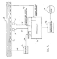
- Fig. 5 zeigt eine schematische Darstellung einer auf den Sensor ansprechenden Vorrichtung, mit der ein oder mehrere Betriebsmerkmale des Fahrzeugs bezüglich der Schiene bestimmt werden.
- 1 is a partial perspective view of a vehicle mounted on an electrified rail carrying an automated robot,
- FIG. 2 is a plan view of a portion of the arrangement shown in FIG. 1, showing a pantograph that supplies power to the vehicle engine from the electrified rail;
- 3 shows a part of the section along the straight line 3-3 from FIG. 2,
- Fig. 4 is a schematic representation of the sensor and the alternating magnetic poles which are formed on the magnetic strip and
- 5 shows a schematic representation of a device responsive to the sensor, with which one or more operating characteristics of the vehicle with respect to the rail are determined.
Fig. 1 zeigt eine über Flur angelegte elektrisch betriebene Fördereinrichtung insbesondere in Art einer hängend betriebenen Fördersystems, bei der ein Fahrzeug 10, insbesondere Schlitten, hängend auf einer Schiene 12 angeordnet ist. Das Fahrzeug 10 trägt einen Industrieroboter 13, welcher für die Beschreibung aber unerheblich ist. Ein Fahrzeug 10 und eine Schiene 12 kann im ganz allgemeinen, in jeder Anwendung benutzt werden, die mit der Bewegung eines Gegenstandes von einem Punkt zum anderen auf einen vorbestimmten Weg verbunden ist.1 shows an electrically operated conveying device which is applied over a corridor, in particular in the manner of a suspended conveying system, in which a
Im allgemeinen beinhaltet das Fahrzeug 10 einen unteren Rahmen 14 mit einem Paar nach oben gerichteten vertikalen Stützelementen 16 und 18. Ein Paar horizontaler Träger 20 und 22 sind mit den vertikalen Stützelementen 16 und 18 verbunden und ein Paar Räder bzw. Rollen (in Fig. 1 nicht gezeigt) sind jeweils an einem der horizontalen Träger 20 und 22 angebracht. Die Räder rollen auf dem oberen Teil der Schiene 12 und gewährleisten somit die Bewegung des Fahrzeugs 10 auf der Schiene 12. Wie ebenfalls bekannt ist, beinhaltet das Fahr zeug 10 einen Elektromotor (in Fig. 1 nicht gezeigt), welcher die Räder auf der Schiene 12 antreibt, um das Fahrzeug 10 zu bewegen.Generally, the
Zwischen den Flanschen der Schiene 10 ist eine aus mehreren Leitern bestehende elektrische Vorrichtung 24 angebracht. Die elektrische Vorrichtung 24 beinhaltet mehrere Stromschienen, die in Fig. 1 mit 26, 28, 30 und 32 gekennzeichnet sind. Die Stromschienen 26 32 liefern den Strom für den Fahrzeugmotor, Kontrollsignale für die Steuereinheit und die Masse für das Fahrzeug. Derartige elektrische Einrichtungen werden beispielsweise unter der Bezeichnung "FABA 100" von der Firma "Electromotive Systems" (Inc. of Milwaukee, Wisconsin) verkauft.An
Ein auf das Fahrzeug 10 angebrachtes Gehäuse 34 beinhaltet mehrere Stromschienenkontakte oder Abnehmer, auch Kollektoren genannt, und eine Schnittstelle zu den Stromschienen 26 - 32, welche den Elektromotor des Fahrzeugs mit Strom versorgen. Das Gehäuse 34 beinhaltet ebenfalls mehrere Stromabnehmer 36, die mit dem Elektromotor verdrahtet sind, um die Stromversorgung und die Masseverbindung zu gewährleisten.A
Fig. 2 zeigt eine detaillierte Darstellung der Schnittstelle zwischen der elektrischen Vorrichtung 24 und dem Strom- und Signalabnehmer 36. Wie man sieht, besitzt die Stromschiene 32 eine nach außen gerichtete Kontaktfläche 38, welche an und innerhalb einer Plastikschienenhalterung oder Hänger 40 befestigt ist, die gleichzeitig als Schutzvorrichtung dient.Fig. 2 shows a detailed representation of the interface between the
Der Stromabnehmer 36 beinhaltet eine Klammer 42, durch welche der Stromabnehmer 36 über ein Stützelement 44 an das Fahrzeug 10 befestigt ist. Ein Arm 46 ist mit der Klammer 42 verbunden. Jedes Ende des Armes 46 ist mit einem drehbar gelagerten Kontakthalter ausgestattet. Die Kontakthalter 48, 50 sind mit Kontakten 52 bzw. 54 versehen. Die äußeren Kontaktflächen der Kontakte 52 und 54 sind in Eingriff mit der Kontaktfläche 38 der Stromschiene 32, um Strom, Kontrollsignale und Erdungspotential an den Fahrzeugelektromotor und dessen Steuereinheit über die Drähte 56 bzw. 58 zu liefern.The
In Fig. 3 sieht man, daß die Kontaktfläche 38 eine nach außen gerichtete Fläche einer äußeren Wand 64 ist, bezüglich der mit Abstand innerhalb eine innere Wand 66 angeordnet ist. Wenn auch die Kontaktfläche 38 als eine nach außen gerichtete vertikale Fläche dargestellt ist, kann die Kontaktfläche der Stromschiene 42 gleicherweise eine nach außen oder nach innen weisende horizontal, oder vertikal oder in sonst einer Weise orientierte Fläche der Schiene 32 sein. Ein paar Seitenwände 68, 70 sind zwischen der äußeren Wand 24 und der inneren Wand 66 angeordnet und begrenzen einen kastenartigen Kanal im Innern der Stromschiene 32. Ein Magnetstreifen 72, dessen Details später erläutert werden, ist innerhalb des von den Wänden 64 - 70 begrenzten Kanals der Stromschiene 32 angebracht. Es hat sich gezeigt, daß eine mit einem Magnetstreifen 72 ausgestattete Schiene, die das Erdungspotential liefert, vorteilhaft ist.In Fig. 3 it can be seen that the
Ferner sieht man in Fig. 3, daß das Kontaktglied 54 mit einem magnetischen Sensor 74 versehen ist. Zwei Sensoren werden verwendet, um Störungen zu vermeiden, die von den Übergängen zwischen den magnetischen Bereichen oder durch den Ausfall einer der Sensoren 74 oder 76 verursacht werden. Selbstverständlich können auch ein, zwei oder mehrere Sensoren verwendet werden. Die Sensoren 74, 76 sind mit Ausgangsdrähten 78 bzw. 80 verbunden. Die Sensoren 74 und 76 können solche sein, wie sie von "Microswitch", eine Tochter der Firma Honeywell unter den Nr. SS21BE oder SS22BE hergestellt werden. Die Sensoren 74, 76 sind mit magnetoresistiven Material ausgestattet, das von Silikon eingehüllt wird und einem Epoxydmantel geschützt wird. Jeder der Sensoren beinhaltet einen integrierten Schaltkreis, der ein dem detektierten Magnetfeld entsprechendes digitales Ausgangssignal ausgibt.3 that the
In Fig. 4 sieht man, daß der Magnetstreifen 72 so magnetisiert ist, daß abwechselnd magnetische Nord- und Südpole angeordnet sind und dadurch alternierende Magnetisierungsbereiche bereitgestellt werden. Die folgende Erläuterung bezieht sich auf die Bereiche 80, 82 und 84. Die Linie 86 trennt die Bereiche 80 und 82, und die Linie 88 trennt die Bereiche 82 und 84. Die Linien 86 und 88 stehen senkrecht auf der Bewegungsrichtung des Fahrzeugs 10 entlang der Schiene 12.In Fig. 4 it can be seen that the
Eine andere Möglichkeit besteht darin, einen Magnetstreifen mit Nord- und Südpolen auszustatten, die durch Bereiche ohne magnetischen Fluß getrennt sind.Another possibility is to equip a magnetic stripe with north and south poles, which are separated by areas without magnetic flux.
Während sich das Fahrzeug 10 entlang der Schiene 12 bewegt, erkennen die Sensoren 74 und 76 die alternierenden Magnetisierungsbereiche des Magnetstreifens 72 und öffnen oder schließen einen Schaltkreis in Abhängigkeit davon, ob ein magnetisches Feld vorhanden ist oder nicht. Bereiche ohne magnetischen Fluß sind auf halben Weg zwischen Nord- und Südpol der Bereiche 80, 82 und 84 angeordnet.As the
Fig. 5 zeigt eine Steuereinrichtung für das Fahrzeug 10. Die Sensoren 74 und 76 sind über die Drähte 78 und 80 mit einer Steuereinheit 90 verbunden. Die Steuereinheit 90 kann ein Mikroprozessor, programmierbarer Regler oder ein ähnliches Gerät sein. Jeder der Sensoren 74 und 76 liefert ein Eingangssignal an die Steuereinheit 90. Die Steuereinheit 90 empfängt über den Draht 92 ein Eingangssignal von einer der Stromschienen, die ein Referenzsignal bereitstellt. Die von den Stromschienen gelieferten Eingangssignale können Frequenz-, Spannungs-, Stromsignale, oder eine beliebige Kombination derer sein. Falls z. B. eine bestimmte Geschwindigkeit des Fahrzeugs 10 erwünscht ist, wird die Steuereinheit 90 so programmiert, daß das Fahrzeug sich mit einer bestimmten Geschwindigkeit bewegt, wenn ein bestimmtes Referenzeingangssignal von der Stromschiene an die Steuereinheit 90 gesendet wird. Die Steuereinheit 90 verarbeitet die Eingangssignale von den Sensoren 74 und 76, um die Geschwindigkeit des Fahrzeugs 10 und die vom Fahrzeug zurückgelegte Distanz zu bestimmen. Durch einen Geschwindigkeitsregler, wie z.B. ein einstellbarer Frequenzregler 92, erhöht bzw. erniedrigt die Steuereinheit 90 die Geschwindigkeit des Fahrzeugmotors 94, so daß die erwünschte Geschwindigkeit entsprechend dem Referenzeingangssignal erreicht wird.5 shows a control device for the
Ein Modulator 96 oder ein anderes entsprechendes Übertragungsgerät kann benutzt werden, um die Steuereinheit auf den gewünschten Geschwindigkeitswert zu setzen. Der Modulator 96 kann über den Draht 98 mit der elektrischen Vorrichtung 25 und über den Draht 100 mit der Steuereinheit verbunden werden. Übertragungssignale werden über die Stromschienen der elektrischen Vorrichtung 24 zum Modulator 96 gesendet und darüber an die Steuereinheit 90 weitergeleitet, um Befehle zum Setzen der Geschwindigkeit, der zurückzulegenden Distanz und des Bestimmungsortes umzusetzen.A
Mit der beschriebenen Vorrichtung ist es möglich, laufend die Geschwindigkeit, den Ort und den zurückgelegten Weg des Fahrzeugs (10) anzuzeigen. In einer automatisierten Einrichtung, bei der mehrere Fahrzeuge verwendet werden, kann die Geschwindigkeit jedes einzelnen Fahrzeugs laufend geändert werden, um vorbestimmte Abstände zwischen den Fahrzeugen einzuhalten. In einer Einrichtung zur Stapelung- und Verteilung von Material kann der genaue Ort eines jeden einzelnen Fahrzeugs laufend überprüft werden. Dies sind nur einige Beispiele für die vielfältigen Anwendungsmöglichkeiten eines solchen Systems.With the device described, it is possible to continuously display the speed, the location and the distance traveled by the vehicle (10). In an automated facility where multiple vehicles are used, the speed of each individual vehicle can be continuously changed to maintain predetermined distances between the vehicles. The exact location of each individual vehicle can be continuously checked in a device for stacking and distributing material. These are just a few examples of the many possible uses of such a system.
Eine spezielle Ausführungsform der Erfindung ist bezüglich eines bestimmten Anwendungsfalles beschrieben, aber sowohl die verschiedenartigen Details, als auch bestimmte Anwendungen der Erfindung, könnten verändert werden ohne sich vom Ziel und Zweck der Aufgabenstellung zu entfernen. Der Magnetstreifen könnte auf verschiedene Weise an die Schiene befestigt werden. Der Magnetstreifen kann an der Schiene haften, beispielsweise durch einen Klebstoff, oder an jener angeschraubt sein, aber kann auch an einem anderen Teil des Aufbaus befestigt sein und braucht nicht unbedingt an der Schiene angebracht zu werden. Außerdem könnte man die Schiene 12 auch in die Vertikalebene legen oder in eine zur Horizontalebene geneigten Ebene. Dementspechend würde die Bewegung des Fahrzeugs (10) eine vertikale Komponente aufweisen, und das Fahrzeug könnte auch eine Aufwärts- bzw. Abwärtsbewegung ausführen.A specific embodiment of the invention is described with respect to a specific application, but both the various details and certain applications of the invention could be changed without departing from the aim and purpose of the task. The Magnetic strips could be attached to the rail in various ways. The magnetic strip can adhere to the rail, for example by means of an adhesive, or can be screwed onto it, but can also be attached to another part of the structure and does not necessarily have to be attached to the rail. In addition, the
Claims (11)
- einer Schiene, die das Fahrzeug trägt und auf der das Fahrzeug bewegbar ist;
- einer Vorrichtung zur Bewegung des Fahrzeugs auf der Schiene;
- einer auf der Schiene montierten stationären magnetischen Vorrichtung, welche mit alternierenden Magnetisierungsbereichen ausgestattet ist, deren magnetischer Fluß nicht parallel zur Bewegungsrichtung des schienengebundenen Fahrzeugs ausgerichtet ist;
- einer an dem Fahrzeug angeordneten und mit diesem beweglichen Sensorvorrichtung zur Erfassung der alternierenden Bereiche des magnetischen Flusses der magnetischen Vorrichtung; und
- einer Vorrichtung, die auf die Sensorvorrichtung anspricht, um die Betriebsmerkmale des Fahrzeugs bezüglich der Schiene zu bestimmen.1. System for moving an object with a vehicle carrying the object;
- a rail that supports the vehicle and on which the vehicle is movable;
- A device for moving the vehicle on the rail;
a stationary magnetic device mounted on the rail, which is equipped with alternating magnetization areas, the magnetic flux of which is not aligned parallel to the direction of movement of the rail-bound vehicle;
a sensor device arranged on the vehicle and movable with it for detecting the alternating regions of the magnetic flux of the magnetic device; and
a device responsive to the sensor device to determine the operational characteristics of the vehicle with respect to the rail.
eine an der Schiene befestigte stationäre magnetische Vorrichtung mit alternierenden Magnetisierungsbereichen, die nicht parallel zur Richtung der Bewegung des Fahrzeugs auf der Schiene ausgerichtet sind,
eine Sensorvorrichtung, die am Fahrzeug befestigt ist und damit bewegt werden kann und die die alternierenden Magnetisierungsbereiche der magnetischen Vorrichtung erkennt und eine auf den Sensor ansprechende Vorrichtung, um einen oder mehrere Betriebsmerkmale des Fahrzeugs bezüglich der Schiene zu bestimmen.10. An apparatus for determining one or more operational characteristics of a vehicle with respect to a rail for a system for moving objects with a vehicle, a rail that supports the vehicle and on which the vehicle is movable, and a device for moving the vehicle on the Rail marked by
a stationary magnetic device fastened to the rail with alternating magnetization regions which are not aligned parallel to the direction of movement of the vehicle on the rail,
a sensor device which is attached to the vehicle and can be moved therewith and which detects the alternating magnetization regions of the magnetic device and a device responsive to the sensor for determining one or more operating characteristics of the vehicle with respect to the rail.
- Bereitstellens eines magnetisierbaren Elementes,
- Magnetisierens des magnetisierbaren Elements, um alternierende Magnetisierungsbereiche anzuordnen,
- Anordnens des magnetisierbaren Elementes an der Schiene, so daß das magnetische Bauteil bezüglich der Schiene in einem stationären Zustand gehalten wird und die alternierenden Magnetisierungsbereiche so ausgerichtet sind, daß sie nicht parallel zur Bewegungsrichtung des Fahrzeugs auf der Schiene liegen,
- Bereitstellens eines Sensors,
- Anordnens des Sensors am Fahrzeug, so daß der Sensor die alternierenden Magnetisierungsbereiche auf dem magnetisierbaren Bauteil erkennt, während sich das Fahrzeug auf der Schiene bewegt, ein dem Magnetierungsbereich entsprechendes Signal ausgibt, und
- Bestimmens eines oder mehrerer Betriebsmerkmale des Fahrzeugs bezüglich der Schiene aus den vom Sensor ausgegebenen Signalen.11. A method for determining one or more operational characteristics of a vehicle with respect to a rail in a system for moving objects with a vehicle, a rail that supports the vehicle and on which the vehicle is movable, and a device for moving the vehicle the rail, characterized by steps of the
Provision of a magnetizable element,
Magnetizing the magnetizable element in order to arrange alternating magnetization regions,
Arranging the magnetizable element on the rail so that the magnetic component is held in a stationary state with respect to the rail and the alternating magnetization regions are aligned such that they are not parallel to the direction of movement of the vehicle on the rail,
Provision of a sensor,
Arranging the sensor on the vehicle so that the sensor detects the alternating magnetization areas on the magnetizable component while the vehicle is moving on the rail, outputs a signal corresponding to the magnetization area, and
- Determining one or more operating characteristics of the vehicle with respect to the rail from the signals output by the sensor.
Applications Claiming Priority (2)
| Application Number | Priority Date | Filing Date | Title |
|---|---|---|---|
| US43048889A | 1989-11-01 | 1989-11-01 | |
| US430488 | 1989-11-01 |
Publications (3)
| Publication Number | Publication Date |
|---|---|
| EP0425772A2 true EP0425772A2 (en) | 1991-05-08 |
| EP0425772A3 EP0425772A3 (en) | 1992-11-25 |
| EP0425772B1 EP0425772B1 (en) | 1995-03-22 |
Family
ID=23707768
Family Applications (1)
| Application Number | Title | Priority Date | Filing Date |
|---|---|---|---|
| EP90114871A Expired - Lifetime EP0425772B1 (en) | 1989-11-01 | 1990-08-02 | Device and method for the determination of one or several operating data of a rail bound vehicle |
Country Status (4)
| Country | Link |
|---|---|
| US (1) | US5141183A (en) |
| EP (1) | EP0425772B1 (en) |
| AT (1) | ATE120145T1 (en) |
| DE (1) | DE59008756D1 (en) |
Cited By (9)
| Publication number | Priority date | Publication date | Assignee | Title |
|---|---|---|---|---|
| US5311509A (en) * | 1991-09-13 | 1994-05-10 | International Business Machines Corporation | Configurable gigabits switch adapter |
| EP0626299A1 (en) | 1993-05-26 | 1994-11-30 | Fahrleitungsbau GmbH | Position detecting device of a vehicle movable along a rail |
| WO1996008675A1 (en) * | 1994-09-12 | 1996-03-21 | Westinghouse Electric Corporation | Remotely operated managed maintenance robotic system |
| EP0937965A1 (en) * | 1998-02-19 | 1999-08-25 | Alfred Ing. Della Torre | Positioning system |
| WO2003022619A1 (en) * | 2001-09-11 | 2003-03-20 | Societe D'etudes Et De Realisations Industrielles Lyonnaises S.E.R.I.L. | Electric supply rail with collecting carriage |
| WO2012089312A1 (en) * | 2010-12-29 | 2012-07-05 | Eisenmann Ag | Conveyor system for transporting objects as well as vehicle and method for operating same |
| EP2799277A3 (en) * | 2013-05-03 | 2015-11-11 | Heinrich GmbH | Current rail and current rail system |
| DE102017010062A1 (en) * | 2017-10-27 | 2019-05-02 | Kuka Ag | Manufacturing system and method for operating a manufacturing system |
| WO2019148846A1 (en) * | 2018-02-05 | 2019-08-08 | 刘春梅 | Self-inspection system for railway traffic intelligent routing inspection robot |
Families Citing this family (11)
| Publication number | Priority date | Publication date | Assignee | Title |
|---|---|---|---|---|
| JP3347766B2 (en) * | 1992-06-08 | 2002-11-20 | 日本トムソン株式会社 | Linear encoder and guide unit having the same |
| SE515008C2 (en) * | 1994-07-04 | 2001-05-28 | Daimler Chrysler Ag | Device for speed measurement in rail vehicles |
| ATE352452T1 (en) | 1997-05-02 | 2007-02-15 | Automation Tooling Syst | MODULAR CONVEYOR SYSTEM WITH MULTIPLE MOVING ELEMENTS UNDER INDEPENDENT CONTROL |
| CA2284855C (en) * | 1999-10-05 | 2002-01-01 | Gestion Techno-Medic Inc. | Automatic displacement and homing system for a rail mounted patient lift |
| DE10362123B4 (en) * | 2003-08-11 | 2011-03-24 | Manfred Josef Wallner | Suspended crane runway and suspended crane runway profile |
| US8224509B2 (en) * | 2006-08-25 | 2012-07-17 | General Atomics | Linear synchronous motor with phase control |
| US20090063084A1 (en) * | 2007-09-04 | 2009-03-05 | Jensen Kevin R | Power rail impact analysis system |
| CN103776896B (en) * | 2014-01-22 | 2016-07-06 | 中国民航大学 | A kind of in-service rod member magnetic flux test system and control method |
| US11813542B2 (en) * | 2020-05-08 | 2023-11-14 | Universal City Studios Llc | Ride vehicle tracking system |
| CN112388606B (en) * | 2020-11-19 | 2022-02-18 | 上海电气集团股份有限公司 | Method and device for detecting bolt state in wind driven generator |
| CN114029955B (en) * | 2021-11-21 | 2023-06-30 | 北京华能新锐控制技术有限公司 | Position determining method and system for annular orbit robot |
Citations (3)
| Publication number | Priority date | Publication date | Assignee | Title |
|---|---|---|---|---|
| FR2164639A1 (en) * | 1971-12-23 | 1973-08-03 | Siemens Ag | |
| US3964702A (en) * | 1973-01-15 | 1976-06-22 | Engins Matra | Anti-collision safety device for a passenger transport system on tracks |
| GB2204434A (en) * | 1987-01-02 | 1988-11-09 | C I Electronics Limited | Control system for a powered rail vehicle |
Family Cites Families (15)
| Publication number | Priority date | Publication date | Assignee | Title |
|---|---|---|---|---|
| US2576424A (en) * | 1945-05-09 | 1951-11-27 | Philco Corp | Automatic speed control for railguided vehicles |
| US3085646A (en) * | 1960-07-25 | 1963-04-16 | Bendix Corp | Motor vehicle control system |
| US3518422A (en) * | 1966-05-16 | 1970-06-30 | Railway Maintenance Corp | Vehicle control apparatus |
| US3800935A (en) * | 1971-09-30 | 1974-04-02 | Fauver J Inc | Conveyor drive control system |
| DE2617943B2 (en) * | 1976-04-24 | 1978-02-16 | Messerschmitt-Bölkow-Blohm GmbH, 8000 München | DEVICE FOR CONTACTLESS TRAVEL AND SPEED MEASUREMENTS IN TRACK-BASED VEHICLES |
| US4168770A (en) * | 1976-05-06 | 1979-09-25 | Westinghouse Electric Corp. | Power collection apparatus for a transportation system |
| SU574758A1 (en) * | 1976-05-17 | 1977-09-30 | Ворошиловградский машиностроительный институт | Apparatus for locating rail vehicles |
| JPS62204118A (en) * | 1986-03-05 | 1987-09-08 | Hitachi Ltd | Magnetically detecting device for position or speed |
| US4766547A (en) * | 1986-04-14 | 1988-08-23 | Transfer Technologies, Inc. | Computer controlled conveyor system |
| FR2598375B1 (en) * | 1986-05-07 | 1988-07-15 | Spitz Martin | SPEED CONTROL ON RAILWAY AND AUTOMATIC DRIVING OF TRAINS |
| US4919057A (en) * | 1987-03-23 | 1990-04-24 | J. N. Fauver Comany, Inc. | Conveyor control through binary coding |
| US5003260A (en) * | 1987-05-28 | 1991-03-26 | Auchterlonie Richard C | Inductive position sensor having plural phase windings on a support and a displaceable phase sensing element returning a phase indicating signal by electromagnetic induction to eliminate wire connections |
| US4924164A (en) * | 1988-04-08 | 1990-05-08 | J. N. Fauver Company, Inc. | Software zoning of conveyor control |
| JPH01320433A (en) * | 1988-06-22 | 1989-12-26 | Seiko Epson Corp | Linear encoder |
| US4892980A (en) * | 1988-08-03 | 1990-01-09 | J. N. Fauver Company | Dual contacts on voltage rail |
-
1990
- 1990-08-02 DE DE59008756T patent/DE59008756D1/en not_active Expired - Fee Related
- 1990-08-02 EP EP90114871A patent/EP0425772B1/en not_active Expired - Lifetime
- 1990-08-02 AT AT90114871T patent/ATE120145T1/en not_active IP Right Cessation
- 1990-12-21 US US07/632,186 patent/US5141183A/en not_active Expired - Lifetime
Patent Citations (3)
| Publication number | Priority date | Publication date | Assignee | Title |
|---|---|---|---|---|
| FR2164639A1 (en) * | 1971-12-23 | 1973-08-03 | Siemens Ag | |
| US3964702A (en) * | 1973-01-15 | 1976-06-22 | Engins Matra | Anti-collision safety device for a passenger transport system on tracks |
| GB2204434A (en) * | 1987-01-02 | 1988-11-09 | C I Electronics Limited | Control system for a powered rail vehicle |
Non-Patent Citations (1)
| Title |
|---|
| CONTROL ENGINEERING Bd. 15, Nr. 3, März 1968, NEW YORK US Seite 54 'Encoded Tracks Tell Train Location' * |
Cited By (9)
| Publication number | Priority date | Publication date | Assignee | Title |
|---|---|---|---|---|
| US5311509A (en) * | 1991-09-13 | 1994-05-10 | International Business Machines Corporation | Configurable gigabits switch adapter |
| EP0626299A1 (en) | 1993-05-26 | 1994-11-30 | Fahrleitungsbau GmbH | Position detecting device of a vehicle movable along a rail |
| WO1996008675A1 (en) * | 1994-09-12 | 1996-03-21 | Westinghouse Electric Corporation | Remotely operated managed maintenance robotic system |
| EP0937965A1 (en) * | 1998-02-19 | 1999-08-25 | Alfred Ing. Della Torre | Positioning system |
| WO2003022619A1 (en) * | 2001-09-11 | 2003-03-20 | Societe D'etudes Et De Realisations Industrielles Lyonnaises S.E.R.I.L. | Electric supply rail with collecting carriage |
| WO2012089312A1 (en) * | 2010-12-29 | 2012-07-05 | Eisenmann Ag | Conveyor system for transporting objects as well as vehicle and method for operating same |
| EP2799277A3 (en) * | 2013-05-03 | 2015-11-11 | Heinrich GmbH | Current rail and current rail system |
| DE102017010062A1 (en) * | 2017-10-27 | 2019-05-02 | Kuka Ag | Manufacturing system and method for operating a manufacturing system |
| WO2019148846A1 (en) * | 2018-02-05 | 2019-08-08 | 刘春梅 | Self-inspection system for railway traffic intelligent routing inspection robot |
Also Published As
| Publication number | Publication date |
|---|---|
| DE59008756D1 (en) | 1995-04-27 |
| US5141183A (en) | 1992-08-25 |
| ATE120145T1 (en) | 1995-04-15 |
| EP0425772B1 (en) | 1995-03-22 |
| EP0425772A3 (en) | 1992-11-25 |
Similar Documents
| Publication | Publication Date | Title |
|---|---|---|
| EP0425772B1 (en) | Device and method for the determination of one or several operating data of a rail bound vehicle | |
| DE60214761T2 (en) | Guidance system and method for driverless vehicle | |
| DE2949204A1 (en) | SYSTEM WITH AUTOMATICALLY CONTROLLED VEHICLES | |
| DE102006025240A1 (en) | Roller conveyor system and method for its control | |
| EP0820862B1 (en) | Apparatus for transporting and threading-in of webs having an electric drive | |
| DE102016222806B3 (en) | Transport goods carrier, transport system and method for transporting a cargo | |
| DE102012016519A1 (en) | Vehicle external control device for autonomous movement of motor vehicle during assembly, has electric drive, which is coupled to motor vehicle, where electric drive and steering of motor vehicle are controlled during assembly steps | |
| DE69817355T2 (en) | COLLECTORS FOR AN ELECTRIC VEHICLE SUPPLIED BY A SELF-INSULATED POWER LINE | |
| DE3219382A1 (en) | METHOD FOR CHANGING THE DIRECTION OF AN ELECTROMAGNETICALLY GUIDED, DRIVERLESS VEHICLE | |
| EP0294731A2 (en) | Production line and method for the production of work pieces thereon | |
| EP3976447B1 (en) | System comprising a tugger train and at least one stationary transfer station | |
| DE102012110581B4 (en) | Improved cleanroom shuttle | |
| DE3120648A1 (en) | Arrangement for supplying electric vehicles with power | |
| EP1177962B1 (en) | Device for monitoring the condition of an Eddy current brake at a railway vehicle | |
| EP1016307A1 (en) | Device and method for automating conveyor systems | |
| EP0493527B1 (en) | Process and device for aligning and joint processing of limp workpiece layers | |
| EP0298194B1 (en) | Electrical drive | |
| DE19733547C2 (en) | Control and position detection of conveyor systems with linear synchronous motor drive | |
| EP3282336A1 (en) | Driverless transport device and method for navigation and positioning of a driverless transport device | |
| DE3418244A1 (en) | TROLLEY FOR TRANSPORTING CASSETTE WITH SEMICONDUCTOR BOARD | |
| DE102022002372B3 (en) | Method of transporting an object | |
| DE2932932A1 (en) | DEVICE FOR SOLDERING A MULTIPLE PLUG WITH A PRINTING CARD | |
| EP0826135A1 (en) | Device for continuously measuring the position of a moving rail vehicle | |
| WO2015162453A1 (en) | Improved cleanroom shuttle | |
| DE10037595A1 (en) | Underfloor rails-conveying system with floor transporter driven by electric motor with current collector arm |
Legal Events
| Date | Code | Title | Description |
|---|---|---|---|
| PUAI | Public reference made under article 153(3) epc to a published international application that has entered the european phase |
Free format text: ORIGINAL CODE: 0009012 |
|
| AK | Designated contracting states |
Kind code of ref document: A2 Designated state(s): AT BE CH DE DK ES FR GB GR IT LI LU NL SE |
|
| PUAL | Search report despatched |
Free format text: ORIGINAL CODE: 0009013 |
|
| AK | Designated contracting states |
Kind code of ref document: A3 Designated state(s): AT BE CH DE DK ES FR GB GR IT LI LU NL SE |
|
| 17P | Request for examination filed |
Effective date: 19930107 |
|
| 17Q | First examination report despatched |
Effective date: 19931221 |
|
| GRAA | (expected) grant |
Free format text: ORIGINAL CODE: 0009210 |
|
| AK | Designated contracting states |
Kind code of ref document: B1 Designated state(s): AT BE CH DE DK ES FR GB GR IT LI LU NL SE |
|
| PG25 | Lapsed in a contracting state [announced via postgrant information from national office to epo] |
Ref country code: NL Free format text: LAPSE BECAUSE OF NON-PAYMENT OF DUE FEES Effective date: 19950322 Ref country code: GR Free format text: LAPSE BECAUSE OF FAILURE TO SUBMIT A TRANSLATION OF THE DESCRIPTION OR TO PAY THE FEE WITHIN THE PRESCRIBED TIME-LIMIT Effective date: 19950322 Ref country code: ES Free format text: THE PATENT HAS BEEN ANNULLED BY A DECISION OF A NATIONAL AUTHORITY Effective date: 19950322 Ref country code: DK Effective date: 19950322 Ref country code: BE Effective date: 19950322 |
|
| REF | Corresponds to: |
Ref document number: 120145 Country of ref document: AT Date of ref document: 19950415 Kind code of ref document: T |
|
| REF | Corresponds to: |
Ref document number: 59008756 Country of ref document: DE Date of ref document: 19950427 |
|
| ET | Fr: translation filed | ||
| ITF | It: translation for a ep patent filed |
Owner name: MODIANO & ASSOCIATI S.R.L. |
|
| PG25 | Lapsed in a contracting state [announced via postgrant information from national office to epo] |
Ref country code: SE Effective date: 19950622 |
|
| GBT | Gb: translation of ep patent filed (gb section 77(6)(a)/1977) |
Effective date: 19950621 |
|
| PG25 | Lapsed in a contracting state [announced via postgrant information from national office to epo] |
Ref country code: AT Effective date: 19950802 |
|
| PG25 | Lapsed in a contracting state [announced via postgrant information from national office to epo] |
Ref country code: LU Free format text: LAPSE BECAUSE OF NON-PAYMENT OF DUE FEES Effective date: 19950831 Ref country code: LI Effective date: 19950831 Ref country code: CH Effective date: 19950831 |
|
| NLV1 | Nl: lapsed or annulled due to failure to fulfill the requirements of art. 29p and 29m of the patents act | ||
| PLBE | No opposition filed within time limit |
Free format text: ORIGINAL CODE: 0009261 |
|
| STAA | Information on the status of an ep patent application or granted ep patent |
Free format text: STATUS: NO OPPOSITION FILED WITHIN TIME LIMIT |
|
| 26N | No opposition filed | ||
| REG | Reference to a national code |
Ref country code: CH Ref legal event code: PL |
|
| PGFP | Annual fee paid to national office [announced via postgrant information from national office to epo] |
Ref country code: FR Payment date: 19960810 Year of fee payment: 7 |
|
| PGFP | Annual fee paid to national office [announced via postgrant information from national office to epo] |
Ref country code: GB Payment date: 19960819 Year of fee payment: 7 |
|
| PG25 | Lapsed in a contracting state [announced via postgrant information from national office to epo] |
Ref country code: GB Free format text: LAPSE BECAUSE OF NON-PAYMENT OF DUE FEES Effective date: 19970802 |
|
| GBPC | Gb: european patent ceased through non-payment of renewal fee |
Effective date: 19970802 |
|
| PG25 | Lapsed in a contracting state [announced via postgrant information from national office to epo] |
Ref country code: FR Free format text: LAPSE BECAUSE OF NON-PAYMENT OF DUE FEES Effective date: 19980430 |
|
| REG | Reference to a national code |
Ref country code: FR Ref legal event code: ST |
|
| PGFP | Annual fee paid to national office [announced via postgrant information from national office to epo] |
Ref country code: DE Payment date: 20031029 Year of fee payment: 14 |
|
| PG25 | Lapsed in a contracting state [announced via postgrant information from national office to epo] |
Ref country code: DE Free format text: LAPSE BECAUSE OF NON-PAYMENT OF DUE FEES Effective date: 20050301 |
|
| PG25 | Lapsed in a contracting state [announced via postgrant information from national office to epo] |
Ref country code: IT Free format text: LAPSE BECAUSE OF NON-PAYMENT OF DUE FEES;WARNING: LAPSES OF ITALIAN PATENTS WITH EFFECTIVE DATE BEFORE 2007 MAY HAVE OCCURRED AT ANY TIME BEFORE 2007. THE CORRECT EFFECTIVE DATE MAY BE DIFFERENT FROM THE ONE RECORDED. Effective date: 20050802 |