EP0427632B1 - Bi-directional snap action register display mechanism - Google Patents
Bi-directional snap action register display mechanism Download PDFInfo
- Publication number
- EP0427632B1 EP0427632B1 EP90403171A EP90403171A EP0427632B1 EP 0427632 B1 EP0427632 B1 EP 0427632B1 EP 90403171 A EP90403171 A EP 90403171A EP 90403171 A EP90403171 A EP 90403171A EP 0427632 B1 EP0427632 B1 EP 0427632B1
- Authority
- EP
- European Patent Office
- Prior art keywords
- cam
- register
- wheel
- display
- directional
- Prior art date
- Legal status (The legal status is an assumption and is not a legal conclusion. Google has not performed a legal analysis and makes no representation as to the accuracy of the status listed.)
- Expired - Lifetime
Links
Images


Classifications
-
- G—PHYSICS
- G06—COMPUTING; CALCULATING OR COUNTING
- G06M—COUNTING MECHANISMS; COUNTING OF OBJECTS NOT OTHERWISE PROVIDED FOR
- G06M1/00—Design features of general application
- G06M1/22—Design features of general application for visual indication of the result of count on counting mechanisms, e.g. by window with magnifying lens
- G06M1/26—Aligning means
-
- G—PHYSICS
- G06—COMPUTING; CALCULATING OR COUNTING
- G06M—COUNTING MECHANISMS; COUNTING OF OBJECTS NOT OTHERWISE PROVIDED FOR
- G06M1/00—Design features of general application
- G06M1/14—Design features of general application for transferring a condition from one stage to a higher stage
- G06M1/143—Design features of general application for transferring a condition from one stage to a higher stage with drums
-
- G—PHYSICS
- G06—COMPUTING; CALCULATING OR COUNTING
- G06M—COUNTING MECHANISMS; COUNTING OF OBJECTS NOT OTHERWISE PROVIDED FOR
- G06M1/00—Design features of general application
- G06M1/22—Design features of general application for visual indication of the result of count on counting mechanisms, e.g. by window with magnifying lens
- G06M1/24—Drums; Dials; Pointers
-
- G—PHYSICS
- G06—COMPUTING; CALCULATING OR COUNTING
- G06M—COUNTING MECHANISMS; COUNTING OF OBJECTS NOT OTHERWISE PROVIDED FOR
- G06M1/00—Design features of general application
- G06M1/04—Design features of general application for driving the stage of lowest order
- G06M1/041—Design features of general application for driving the stage of lowest order for drum-type indicating means
Definitions
- the invention relates to the field of register display mechanisms, and more particularly to a mechanical display of the odometer decade counter type which can be operated in both forward and reverse directions with positive indexing of the digits being displayed by the register.
- odometer-type decade counters in order to display the quantity of a commodity (e.g. gas, water or electricity) being measured by the meter.
- These registers take the form of a decade counter having one or more register display wheels mounted side by side along a common axis.
- the least significant digit wheel (generally the rightmost wheel on the display) is connected to a gear train which is turned by the measuring mechanism of the meter.
- the least significant digit wheel is connected to the next most significant digit wheel by a simple escapement mechanism.
- Decade counters of this type are well-known and their operation and construction will not be described in further detail.
- Conventional odometer-type decade counter register display mechanisms include some sort of "roll-back” prevention mechanism which allows the register wheels to rotate in only one direction (e.g. from lower quantities to higher quantities).
- This anti-"roll-back” mechanism conventionally takes the form of a one-way escapement mechanism comprising an asymmetrical cam and spring-loaded "catch” or pin.
- the anti-"roll-back” mechanism is employed to ensure that the meter cannot be tampered with, and specifically to prevent the amount being displayed from being reset to a lower quantity.
- DE-B-1 234 434 discloses an odometer-type decade counter which incorporates a Snap-action display wheel advancement mechanism and anti-"roll-back” mechanism.
- a meter to measure the flow of water or gas or electricity bi-directionally, i.e. into or out of the metering mechanism.
- a consumer who generates his own electricity may pass it back to the electrical utility and receive a credit for the amount so transferred.
- a conventional one-way register mechanism with roll-back prevention is incapable of showing the net transfer of such a commodity.
- the invention comprises a bi-directional snap-action register mechanism for a mechanical register display having at least one display wheel with at least one display position provided thereon.
- a bi-directional cam is mounted coaxially along a shaft with the register display wheel.
- the bi-directional cam consists of two spiral surfaces arranged next to each other, each spiral surface having a smooth portion and a step transition portion. The two spiral surfaces are oriented symmetrically mirror-reversed with respect to each other and arranged along a guide portion of the shaft.
- the bi-directional cam includes means for cooperating with the guide to allow lateral displacement of the bi-directional cam in a direction parallel to a rotational axis of the guide.
- the register mechanism further includes a pin biased by biasing means, such as a spring, into contact with one of the spiral surfaces of the bi-directional cam. Means are provided for coupling the bi-directional cam to the register display wheel.
- rotation of the guide causes the biased pin to engage one of the two spiral surfaces of the bi-directional cam and causes the cam to abruptly rotate through a predetermined angular distance when the rotation of the cam causes the point of contact of the biased pin with the engaged spiral surface to move from the smooth portion of the engaged surface to the step transition portion of the engaged spiral surface.
- the abrupt rotation of the cam is communicated to the display wheel by the coupling means to cause a new display position to be moved into view.
- the biased pin contacts a particular one of the two spiral surfaces of the cam.
- the particular spiral surface which is followed by the biased pin is determined by the direction of rotation of the guide and cam.
- the pin is urged into contact with the spiral surface offering the least amount of rotational resistance to the pin.
- This will be the spiral having its smooth portion adjacent to the point of contact of the pin with the cam, as opposed to the spiral surface having the step transition portion adjacent to the point of contact of the pin with the cam.
- the coupling means comprises a drive wheel mounted between the register display wheel and the bi-directional cam, and a driven wheel mounted coaxially along the shaft and arranged in the same plane as the drive wheel and having an annular opening for receiving the drive wheel.
- the drive wheel includes means for engaging and driving the driven wheel and register display wheel over a predetermined angular distance and for rotating freely with respect to the driven wheel and register display wheel over another predetermined angular distance.
- the drive wheel further includes means coupled to the bi-directional cam to cause the drive wheel to rotate with the bi-directional cam.
- the foregoing arrangement enables the bi-directional cam to "free wheel" with respect to the driven wheel and register display wheel except over a predetermined angular portion of its rotation.
- the register display wheel will be driven through a predetermined angular distance to bring a new display position into view.
- the driven register display wheel is coupled, via a decade counter mechanism, to further register display wheels disposed coaxially along the common shaft. This enables the "snap-action" of the driven register display wheel to be communicated to the other register display wheels.
- a remotely interrogable encoder mechanism may be associated with one or more of the register display wheels.
- the register display mechanism of the present invention is relatively inexpensive to manufacture and is simple in construction and operation, while providing the advantages of unambiguous display readings, low drag and friction, ease of adaptability for use with conventional remotely interrogable register encoder mechanisms, and the ability to operate properly in both forward and reverse directions.
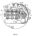
- shaft 1 defines a common rotational axis A and carries on it a driven gear train consisting of a worm gear 3 and driven gear 5.
- Worm gear 3 is connected via driven shaft 7 to a metering mechanism (not shown).
- the metering mechanism is conventional and can comprise, for example, the output from the measuring mechanism of a water meter, gas meter, electricity meter or the like.
- a guide 9 is also disposed along shaft 1 and takes a form of a sleeve having an axial opening 11 for receiving shaft 1.
- One end of guide 9 includes a flattened portion 13 which is arranged to fit into a similarly shaped opening formed about the center of driven gear 5, so that driven gear 5 and guide 9 turn together as a unit about axis A of shaft 1.
- Guide 9 further includes at least one helical groove 15 formed on its surface. Preferably, there are a pair of such grooves 15 formed along the length of guide 9 and disposed oppositely from each other.
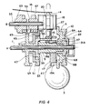
- Bi-directional cam 17 is comprised of two spiral surfaces 19a, 19b arranged next to each other, with each spiral surface having a smooth portion 21a, 21b respectively, and a step transition portion 23a, 23b, respectively.
- Spiral surfaces 19a, 19b are oriented symmetrically mirror-reversed with respect to each other. More specifically, spiral surfaces 19a, 19b are mirror-reversed about a line of symmetry S extending from the common axis A of shaft 1 through a base portion 25 common to the step transition portions 23a, 23b of spiral surfaces 19a, 19b.
- Bi-directional cam 17 may optionally include a wall area 27 which separates the two spiral surfaces 19a and 19b.
- Bi-directional cam 17 further includes an opening 29 adapted to receive guide 9.
- Opening 29 includes means for cooperating with the guide 9 which preferably takes the form of a pair of pins or protrusions 31a, 31b formed on the interior surface of opening 29 and arranged to engage helical grooves 15 formed on the surface of guide 9.
- the interior surface of opening 29 could have one or more helical grooves similar to those shown at 15 formed therein and guide means 9 could be provided with pins or protrusions similar to those noted at 31a and 31b.
- Drive wheel 33 includes an arm 35 which fits within a similarly shaped opening 37 formed in cam 17. Arm 35 of drive wheel 33 fits slidingly within opening 37 of cam 17 in such a fashion so that cam 17 may move laterally in a direction parallel to axis A of shaft 1.
- Drive wheel 33 further includes an annular recessed area 39 which slidingly receives annular area 40 formed on the end of guide 9 opposite flattened portion 13.
- annular lip 41 On the side of drive wheel 33 opposite arm 35 is formed an annular lip 41 which is interrupted over a predetermined angular portion by a protrusion 43 which extends radially outward from annular lip 41 to the outer periphery of drive wheel 33.
- a driven wheel 45 is mounted coaxially along the common shaft 1 and in the same plane as drive wheel 33.
- Driven wheel 45 has an annular opening 47 for slidingly receiving drive wheel 33.
- Also formed on the interior surface of annular opening 47 is a protrusion 49 which prevents drive wheel 33 from freely rotating with respect to driven wheel 45 for something more than 360°, due to the interfering action of protrusion 43 of drive wheel 33 with protrusion 49 of driven wheel 45.
- Pins 51 are designed to engage the teeth 57 of a gear 53.
- Gear 53 is disposed about a shaft 55 mounted parallel to axis A of shaft 1. Teeth 57 of gear 53 also engage a plurality of pins 59 formed about the periphery of register display wheel 61.
- Register display wheel 61 is mounted for rotation about axis A of shaft 1 and includes one or more display positions 63 which, for example, may be the numerals 0, 1, 2, 3, 4, 5, 6, 7, 8, 9 or other such display indicia.
- Register display wheel 61 may further include a pair of pins 65 disposed on the side of register display wheel 61 opposite the bi-directional cam for engaging a gear (not shown) similar in shape to gear 53 and mounted coaxially along shaft 55. This further gear would engage an additional register display wheel (not shown) constructed similarly to register display wheel 61.
- Such an arrangement constitutes a type of decade counter mechanism or odometer-type display whose construction and operation is well known.
- the register display mechanism of the present invention may further include remotely interrogable encoder means associated with at least one register display wheel.
- Such conventional mechanisms may take the form of that shown in U.S. Pat. No. 4,085,287.
- a circuit board 67 is arranged between register display wheels. Each circuit board has a series of electrical contacts 69 formed on both sides of the board and arranged in a circle facing adjacent display wheels. Each display wheel carries an electrical wiper or contact arm 71 which is arranged to contact an individual electrical contact 69 on circuit board 67.
- the position of the wiper arm 71 on a particular electrical contact 69 indicates the position of the register wheel (e.g. register display wheel 61) and the digit or position being displayed.
- driven gear 5 may include a pair of pins 6a, 6b formed on a side of driven gear 5 opposite cam 17. Pins 6a, 6b engage openings 8a, 8b formed in a drive indicator wheel 10.
- Drive indicator wheel 10 includes one or more display positions 12, e.g. the numerals 0-9 or other indicia. Drive indicator wheel 10 is designed to rotate with driven gear 5 and gives a visual indication to an observer of the direction and movement of driven gear 5.
- biasing spring 16 takes the form of a leaf-spring formed from a flexible material, such as copper-bronze. Alternatively, a coil spring could be utilized. Pin 14 is guided by guide block 18 having an opening 20 slidingly receiving pin 14.
- shafts 1 and 55 are formed from steel and the various elements including gears 3, 5, 53, wheels 10, 33, 45, 61, guide 9, cam 17 and pin 14 are formed from a self-lubricating plastic, such as Delrin ⁇ .
- a self-lubricating plastic such as Delrin ⁇ .
- Such plastic parts can be readily molded, are relatively dimensionally stable and because of their self-lubricating characteristics, are smooth-running and exhibit low drag when in contact with each other.
- driven shaft 7 is turned by a metering mechanism (not shown), such as the measurement mechanism from an electricity, gas or water meter. Rotation of shaft 7 turns worm gear 3 causing driven gear 5 to turn. The direction of rotation of driven gear 5 can be readily discerned by observing the motion of drive indicator wheel 10.
- Rotation of driven gear 5 causes guide 9 to turn.
- the interaction of protrusions 31a, 31b with helical grooves 15 formed on guide 9 causes bi-directional cam 17 to move laterally (i.e. in a direction parallel to axis A of shaft 1) in a direction depending upon the direction of rotation of guide 9.
- Pin 14 is biased by spring 16 into contact with the common base portion 25 of the step transition portions 23a, 23b of spiral surfaces 19a, 19b. Since the step transition portion 23a or 23b will represent a path of greater resistance to the point of contact of pin 14 with spiral surface 19a or 19b, cam 17 will move laterally with respect to guide 9 until the point of contact of pin 14 contacts the smooth portion 21a or 21b of spiral surface 19a or 19b, whichever offers the path of least resistance to pin 14.
- cam 17 When cam 17 reaches the end of its lateral displacement with respect to grooves of guide 9, it will begin to rotate with guide 9 and driven gear 5.
- the appropriate smooth portion 21a or 21b of spiral surfaces 19a or 19b will pass beneath the point of contact of pin 14 which remains in contact at all time with the spiral surface due to the biasing force provided by biasing spring 16.
- drive wheel 33 will begin to rotate with cam 17 since arm 35 of drive wheel 33 engages opening 37 of cam 17.
- Drive wheel 33 rotates smoothly within annular opening 47 of driven wheel 45.
- the presence of protrusion 43 on drive wheel 33 and protrusion 49 on driven wheel 45 prevents drive wheel 33 from freely rotating through a full 360° or more.
- the relative widths of protrusions 43 and 49 are dimensioned to provide a predetermined number of degrees of free rotation between drive wheel 33 and driven wheel 45.
- the width of protrusion 43 and 49 may be adjusted to provide approximately 324° of rotational freedom between drive wheel 33 and driven wheel 45.
- the abrupt rotation of cam 17 is communicated to drive wheel 33 through the interaction of arm 35 with opening 37.
- the abrupt rotation of drive wheel 33 in turn is communicated to driven wheel 45 through the interaction of protrusion 43 of drive wheel 33 with protrusion 49 of driven wheel 45.
- Pins 51 of driven wheel 45 engage teeth 57 of gear 53 (which has eight teeth), causing gear 53 to rotate approximately 90° (based upon the example given above).
- Register display wheel 61 engages teeth 57 of gear 53 via two of the twenty pins 59 formed on display wheel 61. Using the example given above, register display wheel 61 will abruptly rotate through approximately 36° or 1/10 of its circumference. This causes a new display position 63 to be brought into view.
- register display wheel When register display wheel has rotated through ten such abrupt movements, pins 65 will engage a gear similar to that of gear 53 to cause a subsequent register display wheel similar to wheel 61 to move to its next display position through this well-known decade counter "odometer-type" display mechanism.
- driven shaft 7 is rotated in a direction opposite to that described above, driven gear 5 will begin rotation in the opposite direction causing guide 9 to rotate and cam 17 to move laterally.
- Drive wheel 33 will once again move freely with respect to driven wheel 45 since protrusion 43 will rotate away from protrusion 49.
- cam 17 has reached the end of its lateral displacement along guide 9, as constrained by the interaction of helical grooves with protrusions 31a, 31b of cam 17, drive wheel 33 will be rotated with respect to driven wheel 45 until protrusion 43 contacts protrusion 49 of driven wheel 45 on a side opposite from that previously described. Because of the lateral displacement of cam 17 with respect to guide 9 and pin 14, pin 14 will follow the smooth portion of the other spiral surface.
- cam 17 Upon rotation of cam 17 such that the point of contact of pin 14 follows the smooth spiral surface until it encounters the step transition portion of the spiral surface, cam 17 will abruptly rotate causing drive wheel 33 to rotate driven wheel 45 through a predetermined angle.
- This movement of driven wheel 45 causes pins 51 to engage teeth 57 of gear 53 which, in turn causes reverse rotation of register display wheel 61 through a predetermined angle to bring a new display position 63 into view.
- shaft 1 acts merely as a support for gear 5, guide 9, wheel 10, cam 17, drive wheel 33 and register display wheel 61.
- gear 5 may rotate freely with respect to shaft 1 whose ends are fixed and which does not rotate.
- shaft 1 may be coupled directly to driven gear 5 so that shaft 1 will rotate with gear 5.
- guide 9 may be formed as an integral part of shaft 1 with grooves 15 being formed directly on the surface of the shaft.
- cam 17, drive wheel 45 and register display wheel 61 would not be fixed with respect to shaft 1 and could rotate independent of shaft 1.
- the foregoing arrangement enables the bi-directional cam 17 to "free wheel" with respect to register display wheel 61 except over a predetermined angular portion of its rotation.
- the register display wheel 61 will be quickly driven through a predetermined angular distance to bring a new display position into view.
- the coupling of display wheel 61 via a well-known decade counter mechanism to further register display wheels disposed coaxially along a common shaft enables the "snap-action" of the driven register display wheel 61 to be communicated to other register display wheels.
- the register display mechanism is relatively inexpensive to manufacture and is simple in construction and operation, while providing the advantages of unambiguous display readings, due to the snap-action of the display mechanism, low drag and friction, ease of adaptability for use with conventional remotely interrogable register encoder mechanisms, and the ability to operate properly in both forward and reverse directions.
Description
Claims (9)
- A bi-directional snap-action register mechanism for a mechanical register display comprising:at least one register display wheel (61) having at least one display position (63) provided thereon:guide means (9) disposed coaxially along a common rotational axis (A), defined by a Shaft (1), with the register display wheel;a bi-directional cam (17) disposed about the guide means, the bi-directional cam comprised of two spiral surfaces (19a, 19b) , each spiral surface having a smooth portion (21a, 21b) and a step transition portion (23a, 23b) provided thereon, the two spiral surfaces being oriented symmetrically mirror-reversed with respect to each other and arranged along a portion of the common shaft having guide means disposed thereon, the bi-directional cam having means (31a, 31b) cooperating with the guide means to allow lateral displacement of the bi-directional cam in a direction parallel to the common rotational axis;a pin (14) biased by biasing means (16) into contact with one of the spiral surfaces of the bi-directional cam; andmeans (35, 33, 45, 53) for coupling the bi-directional cam to the register display wheel;wherein rotation of the guide means causes the biased pin to engage one of the two spiral surfaces of the bi-directional cam and causes the cam to abruptly rotate through a predetermined angular distance when the point of contact of the biased pin with the engaged spiral surface moves from the smooth portion of the engaged surface to the step transition portion of the engaged surface, the abrupt rotation of the cam being communicated to the register display wheel by the coupling means to cause a new display position to be moved into view.
- The register mechanism of claim 1 wherein the biased pin (14) contacts a particular one of the two spiral surfaces (19a, 19b) of the cam (17) depending upon the direction of axial rotation of the guide means (9).
- The register mechanism of claim 1 wherein the coupling means comprises a drive wheel (33) mounted coaxially with the guide means (9) along the common axis between the register display wheel (61) and the bi-directional cam (17), and a driven wheel (45) mounted coaxially along the common axis and in the same plane as the drive wheel, the driven wheel having an annular opening (47) for slidingly receiving the drive wheel, the drive wheel including means (43) for engaging and driving the driven wheel and register display wheel over a predetermined angular distance and for rotating freely with respect to the driven wheel and register display wheel over another predetermined angular distance, the drive wheel further including means (35) coupled to the bi-directional cam to cause the drive wheel to rotate with the bi-directional cam.
- The register mechanism of claim 1 wherein the guide means (9) comprises a helical groove (15) arranged along the common axis to allow movement of the cam (17) in a direction parallel to the common axis and without rotation of the cam with respect to the common axis over a predetermined amount of angular rotation of the guide means.
- The register mechanism of claim 1 wherein the two spiral surfaces (19a, 19b) of the cam are arranged adjacent each other and are mirror-reversed about a line of symmetry (S) extending from the axis (A) of rotation of the cam through a base portion (25) common to the step transition portions (23a, 23b) of the two spiral surfaces.
- The register mechanism of claim 1 further including additional register display wheels disposed coaxially along the common axis and coupled to the register display wheel (61) through a decade counter mechanism.
- The register mechanism of claim 1 further including a gear train (3,5) coupled to the guide means (9) for driving the guide means in a clockwise or counter-clockwise direction.
- The register mechanism of claim 6 wherein the decade counter mechanism is an odometer type mechanical register display.
- The register mechanism of claim 1 further including remotely interrogable encoder means (67, 69, 71) associated with at least one register display wheel.
Applications Claiming Priority (2)
| Application Number | Priority Date | Filing Date | Title |
|---|---|---|---|
| US07/433,864 US5168146A (en) | 1989-11-09 | 1989-11-09 | Bi-directional snap-action register display mechanism |
| US433864 | 1989-11-09 |
Publications (3)
| Publication Number | Publication Date |
|---|---|
| EP0427632A2 EP0427632A2 (en) | 1991-05-15 |
| EP0427632A3 EP0427632A3 (en) | 1993-08-04 |
| EP0427632B1 true EP0427632B1 (en) | 1998-01-21 |
Family
ID=23721834
Family Applications (1)
| Application Number | Title | Priority Date | Filing Date |
|---|---|---|---|
| EP90403171A Expired - Lifetime EP0427632B1 (en) | 1989-11-09 | 1990-11-08 | Bi-directional snap action register display mechanism |
Country Status (4)
| Country | Link |
|---|---|
| US (1) | US5168146A (en) |
| EP (1) | EP0427632B1 (en) |
| CA (1) | CA2029597C (en) |
| DE (1) | DE69031971T2 (en) |
Families Citing this family (21)
| Publication number | Priority date | Publication date | Assignee | Title |
|---|---|---|---|---|
| US5721788A (en) | 1992-07-31 | 1998-02-24 | Corbis Corporation | Method and system for digital image signatures |
| US5832119C1 (en) | 1993-11-18 | 2002-03-05 | Digimarc Corp | Methods for controlling systems using control signals embedded in empirical data |
| US6580819B1 (en) | 1993-11-18 | 2003-06-17 | Digimarc Corporation | Methods of producing security documents having digitally encoded data and documents employing same |
| US5748763A (en) | 1993-11-18 | 1998-05-05 | Digimarc Corporation | Image steganography system featuring perceptually adaptive and globally scalable signal embedding |
| US5768426A (en) | 1993-11-18 | 1998-06-16 | Digimarc Corporation | Graphics processing system employing embedded code signals |
| US7171016B1 (en) | 1993-11-18 | 2007-01-30 | Digimarc Corporation | Method for monitoring internet dissemination of image, video and/or audio files |
| US5862260A (en) | 1993-11-18 | 1999-01-19 | Digimarc Corporation | Methods for surveying dissemination of proprietary empirical data |
| US6424725B1 (en) | 1996-05-16 | 2002-07-23 | Digimarc Corporation | Determining transformations of media signals with embedded code signals |
| US6122403A (en) | 1995-07-27 | 2000-09-19 | Digimarc Corporation | Computer system linked by using information in data objects |
| US6408082B1 (en) | 1996-04-25 | 2002-06-18 | Digimarc Corporation | Watermark detection using a fourier mellin transform |
| US5822436A (en) | 1996-04-25 | 1998-10-13 | Digimarc Corporation | Photographic products and methods employing embedded information |
| US6983051B1 (en) | 1993-11-18 | 2006-01-03 | Digimarc Corporation | Methods for audio watermarking and decoding |
| US6522770B1 (en) | 1999-05-19 | 2003-02-18 | Digimarc Corporation | Management of documents and other objects using optical devices |
| US6721440B2 (en) | 1995-05-08 | 2004-04-13 | Digimarc Corporation | Low visibility watermarks using an out-of-phase color |
| US6577746B1 (en) | 1999-12-28 | 2003-06-10 | Digimarc Corporation | Watermark-based object linking and embedding |
| US6829368B2 (en) | 2000-01-26 | 2004-12-07 | Digimarc Corporation | Establishing and interacting with on-line media collections using identifiers in media signals |
| US6381341B1 (en) | 1996-05-16 | 2002-04-30 | Digimarc Corporation | Watermark encoding method exploiting biases inherent in original signal |
| US7054463B2 (en) | 1998-01-20 | 2006-05-30 | Digimarc Corporation | Data encoding using frail watermarks |
| US6804377B2 (en) | 2000-04-19 | 2004-10-12 | Digimarc Corporation | Detecting information hidden out-of-phase in color channels |
| AU2002228232B2 (en) * | 2001-02-06 | 2006-10-05 | Elster Metering Limited | Flowmeter |
| GB2382195B (en) * | 2001-11-14 | 2005-05-11 | Abb Metering Ltd | Indexing mechanism |
Family Cites Families (7)
| Publication number | Priority date | Publication date | Assignee | Title |
|---|---|---|---|---|
| US3019974A (en) * | 1958-09-11 | 1962-02-06 | Veeder Root Inc | Automatic numeral wheel aligning mechanism |
| US3077302A (en) * | 1960-04-06 | 1963-02-12 | Solari Fermo | Stepping device with accumulation of energy for mechanical counter |
| DE1234434B (en) * | 1960-12-03 | 1967-02-16 | Gretag Ag | Counter |
| US3643072A (en) * | 1970-07-22 | 1972-02-15 | Veeder Industries Inc | Resettable counter |
| US4085287A (en) * | 1975-12-19 | 1978-04-18 | Neptune Water Meter Company | Data transmitting apparatus |
| US4204112A (en) * | 1978-01-27 | 1980-05-20 | Lane Don W | Bidirectional presettable odometer |
| DE2938410C2 (en) * | 1979-09-22 | 1981-10-29 | Kienzle Apparate Gmbh, 7730 Villingen-Schwenningen | Device for scanning the position of a preset counter consisting of several digit rollers provided with control cams |
-
1989
- 1989-11-09 US US07/433,864 patent/US5168146A/en not_active Expired - Lifetime
-
1990
- 1990-11-08 DE DE69031971T patent/DE69031971T2/en not_active Expired - Fee Related
- 1990-11-08 EP EP90403171A patent/EP0427632B1/en not_active Expired - Lifetime
- 1990-11-08 CA CA002029597A patent/CA2029597C/en not_active Expired - Fee Related
Also Published As
| Publication number | Publication date |
|---|---|
| CA2029597C (en) | 2000-01-25 |
| EP0427632A3 (en) | 1993-08-04 |
| US5168146A (en) | 1992-12-01 |
| DE69031971D1 (en) | 1998-02-26 |
| DE69031971T2 (en) | 1998-08-27 |
| CA2029597A1 (en) | 1991-05-10 |
| EP0427632A2 (en) | 1991-05-15 |
Similar Documents
| Publication | Publication Date | Title |
|---|---|---|
| EP0427632B1 (en) | Bi-directional snap action register display mechanism | |
| CA2426596C (en) | Self-powered fluid meter | |
| US4815632A (en) | Liquid dosing device with digital display | |
| CA1103357A (en) | Meter dial encoder for remote meter reading | |
| CN106197485B (en) | Suitable for providing the equipment of the instruction of the Angle Position of input part by repeatedly rotation | |
| CA1224551A (en) | Meter removal indicator | |
| US4740690A (en) | Absolute combinational encoders coupled through a fixed gear ratio | |
| US6333626B1 (en) | Flow meter for converting mechanical rotation into an electronic signal | |
| US3450091A (en) | Multi-turn indicator dial system | |
| US3916713A (en) | Snap action transfer pinion | |
| EP0017874B1 (en) | Gas meter | |
| US4521895A (en) | Pulse generator unit for fuel pump register | |
| US3125291A (en) | High-speed counter | |
| AU626970B2 (en) | Directional spring for ac synchronous motor | |
| US4010464A (en) | Magnetically operated reed switch type digital encoder | |
| US7350693B2 (en) | Indexing mechanism | |
| US4019031A (en) | Register price wheel structure | |
| JPH0338655Y2 (en) | ||
| US4074192A (en) | Keyless unidirectional reset for cumulative demand register | |
| US4164647A (en) | Unidirectional register having different gear ratios for normal and reverse input drive rotation | |
| CN216846389U (en) | Sampling device and gas meter with same | |
| US3962691A (en) | Device for the transmission over a distance of indications in particular of a meter | |
| US4009373A (en) | Electro-mechanical counting register | |
| CN100380100C (en) | Reading mechanism of metering device | |
| US3346182A (en) | Reversible drive |
Legal Events
| Date | Code | Title | Description |
|---|---|---|---|
| PUAI | Public reference made under article 153(3) epc to a published international application that has entered the european phase |
Free format text: ORIGINAL CODE: 0009012 |
|
| AK | Designated contracting states |
Kind code of ref document: A2 Designated state(s): BE CH DE ES FR GB IT LI NL SE |
|
| PUAL | Search report despatched |
Free format text: ORIGINAL CODE: 0009013 |
|
| AK | Designated contracting states |
Kind code of ref document: A3 Designated state(s): BE CH DE ES FR GB IT LI NL SE |
|
| 17P | Request for examination filed |
Effective date: 19940201 |
|
| GRAG | Despatch of communication of intention to grant |
Free format text: ORIGINAL CODE: EPIDOS AGRA |
|
| 17Q | First examination report despatched |
Effective date: 19970122 |
|
| GRAG | Despatch of communication of intention to grant |
Free format text: ORIGINAL CODE: EPIDOS AGRA |
|
| GRAG | Despatch of communication of intention to grant |
Free format text: ORIGINAL CODE: EPIDOS AGRA |
|
| GRAH | Despatch of communication of intention to grant a patent |
Free format text: ORIGINAL CODE: EPIDOS IGRA |
|
| GRAH | Despatch of communication of intention to grant a patent |
Free format text: ORIGINAL CODE: EPIDOS IGRA |
|
| GRAG | Despatch of communication of intention to grant |
Free format text: ORIGINAL CODE: EPIDOS AGRA |
|
| GRAA | (expected) grant |
Free format text: ORIGINAL CODE: 0009210 |
|
| AK | Designated contracting states |
Kind code of ref document: B1 Designated state(s): BE CH DE ES FR GB IT LI NL SE |
|
| PG25 | Lapsed in a contracting state [announced via postgrant information from national office to epo] |
Ref country code: ES Free format text: THE PATENT HAS BEEN ANNULLED BY A DECISION OF A NATIONAL AUTHORITY Effective date: 19980121 |
|
| REG | Reference to a national code |
Ref country code: CH Ref legal event code: EP |
|
| REF | Corresponds to: |
Ref document number: 69031971 Country of ref document: DE Date of ref document: 19980226 |
|
| ITF | It: translation for a ep patent filed |
Owner name: BARZANO' E ZANARDO MILANO S.P.A. |
|
| PG25 | Lapsed in a contracting state [announced via postgrant information from national office to epo] |
Ref country code: SE Free format text: LAPSE BECAUSE OF FAILURE TO SUBMIT A TRANSLATION OF THE DESCRIPTION OR TO PAY THE FEE WITHIN THE PRESCRIBED TIME-LIMIT Effective date: 19980421 |
|
| ET | Fr: translation filed | ||
| PLBE | No opposition filed within time limit |
Free format text: ORIGINAL CODE: 0009261 |
|
| STAA | Information on the status of an ep patent application or granted ep patent |
Free format text: STATUS: NO OPPOSITION FILED WITHIN TIME LIMIT |
|
| PG25 | Lapsed in a contracting state [announced via postgrant information from national office to epo] |
Ref country code: LI Free format text: LAPSE BECAUSE OF NON-PAYMENT OF DUE FEES Effective date: 19981130 Ref country code: CH Free format text: LAPSE BECAUSE OF NON-PAYMENT OF DUE FEES Effective date: 19981130 Ref country code: BE Free format text: LAPSE BECAUSE OF NON-PAYMENT OF DUE FEES Effective date: 19981130 |
|
| 26N | No opposition filed | ||
| BERE | Be: lapsed |
Owner name: SCHLUMBERGER INDUSTRIES INC. (A DELAWARE CORP.) Effective date: 19981130 |
|
| PG25 | Lapsed in a contracting state [announced via postgrant information from national office to epo] |
Ref country code: NL Free format text: LAPSE BECAUSE OF NON-PAYMENT OF DUE FEES Effective date: 19990601 |
|
| REG | Reference to a national code |
Ref country code: CH Ref legal event code: PL |
|
| NLV4 | Nl: lapsed or anulled due to non-payment of the annual fee |
Effective date: 19990601 |
|
| PGFP | Annual fee paid to national office [announced via postgrant information from national office to epo] |
Ref country code: GB Payment date: 20011029 Year of fee payment: 12 |
|
| PGFP | Annual fee paid to national office [announced via postgrant information from national office to epo] |
Ref country code: DE Payment date: 20011126 Year of fee payment: 12 |
|
| REG | Reference to a national code |
Ref country code: GB Ref legal event code: IF02 |
|
| REG | Reference to a national code |
Ref country code: FR Ref legal event code: CD |
|
| REG | Reference to a national code |
Ref country code: FR Ref legal event code: TP |
|
| PG25 | Lapsed in a contracting state [announced via postgrant information from national office to epo] |
Ref country code: GB Free format text: LAPSE BECAUSE OF NON-PAYMENT OF DUE FEES Effective date: 20021108 |
|
| PGFP | Annual fee paid to national office [announced via postgrant information from national office to epo] |
Ref country code: FR Payment date: 20021128 Year of fee payment: 13 |
|
| PG25 | Lapsed in a contracting state [announced via postgrant information from national office to epo] |
Ref country code: DE Free format text: LAPSE BECAUSE OF NON-PAYMENT OF DUE FEES Effective date: 20030603 |
|
| GBPC | Gb: european patent ceased through non-payment of renewal fee | ||
| PG25 | Lapsed in a contracting state [announced via postgrant information from national office to epo] |
Ref country code: FR Free format text: LAPSE BECAUSE OF NON-PAYMENT OF DUE FEES Effective date: 20040730 |
|
| REG | Reference to a national code |
Ref country code: FR Ref legal event code: ST |
|
| PG25 | Lapsed in a contracting state [announced via postgrant information from national office to epo] |
Ref country code: IT Free format text: LAPSE BECAUSE OF NON-PAYMENT OF DUE FEES Effective date: 20051108 |