EP0428164A2 - Animation producing apparatus - Google Patents
Animation producing apparatus Download PDFInfo
- Publication number
- EP0428164A2 EP0428164A2 EP90121824A EP90121824A EP0428164A2 EP 0428164 A2 EP0428164 A2 EP 0428164A2 EP 90121824 A EP90121824 A EP 90121824A EP 90121824 A EP90121824 A EP 90121824A EP 0428164 A2 EP0428164 A2 EP 0428164A2
- Authority
- EP
- European Patent Office
- Prior art keywords
- animation
- parameters
- plurality set
- parameter
- fundamental
- Prior art date
- Legal status (The legal status is an assumption and is not a legal conclusion. Google has not performed a legal analysis and makes no representation as to the accuracy of the status listed.)
- Granted
Links
Images


Classifications
-
- G—PHYSICS
- G06—COMPUTING; CALCULATING OR COUNTING
- G06T—IMAGE DATA PROCESSING OR GENERATION, IN GENERAL
- G06T13/00—Animation
- G06T13/80—2D [Two Dimensional] animation, e.g. using sprites
-
- G—PHYSICS
- G06—COMPUTING; CALCULATING OR COUNTING
- G06T—IMAGE DATA PROCESSING OR GENERATION, IN GENERAL
- G06T13/00—Animation
- G06T13/20—3D [Three Dimensional] animation
- G06T13/40—3D [Three Dimensional] animation of characters, e.g. humans, animals or virtual beings
-
- G—PHYSICS
- G05—CONTROLLING; REGULATING
- G05B—CONTROL OR REGULATING SYSTEMS IN GENERAL; FUNCTIONAL ELEMENTS OF SUCH SYSTEMS; MONITORING OR TESTING ARRANGEMENTS FOR SUCH SYSTEMS OR ELEMENTS
- G05B2219/00—Program-control systems
- G05B2219/30—Nc systems
- G05B2219/36—Nc in input of data, input key till input tape
- G05B2219/36171—Edit velocity, motion profile, graphic plot of speed as function of time, position
-
- G—PHYSICS
- G05—CONTROLLING; REGULATING
- G05B—CONTROL OR REGULATING SYSTEMS IN GENERAL; FUNCTIONAL ELEMENTS OF SUCH SYSTEMS; MONITORING OR TESTING ARRANGEMENTS FOR SUCH SYSTEMS OR ELEMENTS
- G05B2219/00—Program-control systems
- G05B2219/30—Nc systems
- G05B2219/36—Nc in input of data, input key till input tape
- G05B2219/36487—Record position, motion and sound
-
- G—PHYSICS
- G05—CONTROLLING; REGULATING
- G05B—CONTROL OR REGULATING SYSTEMS IN GENERAL; FUNCTIONAL ELEMENTS OF SUCH SYSTEMS; MONITORING OR TESTING ARRANGEMENTS FOR SUCH SYSTEMS OR ELEMENTS
- G05B2219/00—Program-control systems
- G05B2219/30—Nc systems
- G05B2219/40—Robotics, robotics mapping to robotics vision
- G05B2219/40395—Compose movement with primitive movement segments from database
-
- G—PHYSICS
- G05—CONTROLLING; REGULATING
- G05B—CONTROL OR REGULATING SYSTEMS IN GENERAL; FUNCTIONAL ELEMENTS OF SUCH SYSTEMS; MONITORING OR TESTING ARRANGEMENTS FOR SUCH SYSTEMS OR ELEMENTS
- G05B2219/00—Program-control systems
- G05B2219/30—Nc systems
- G05B2219/45—Nc applications
- G05B2219/45176—Animation for film scenes, show
Definitions
- the present invention generally relates to animation producing apparatus for producing animations and, more particularly, is directed to an animation producing apparatus which produces an animation by using a plurality set of parameters and a plurality set of fundamental shapes.
- Fig. 1 shows a conventional animation producing apparatus which utilizes computer graphics.
- reference numeral 1 designates a keyboard, 2 a video image input apparatus such as a digitizer or the like, 3 a central processing unit (CPU), 4 a memory such as a random access memory (RAM), magnetic disc apparatus or the like, and 5 a video image display apparatus such as a cathode ray tube (CRT) and so on.
- Data of a fundamental configuration i.e. fundamental shapes of a predetermined character are stored in the memory 4 from the keyboard 1 and the video image input apparatus 2 through the CPU 3.
- the data of the fundamental shape of the character itself may be generated by an operation of the computer (see U.S. Pat. No. 4,791,581).
- man's motions can be expressed by a parameter group P which is formed of three parameters (i.e. parameter for designating waving of arms, parameter for designating motion of legs and parameter designating moving amount of character in the lateral direction).
- the operator operates the keyboard 1 to set in the memory 4 values P0, P1 and P2 of the parameter group P at timing points t0, t1 and t2 in one time line T.
- the CPU 3 performs interpolation operation to generate values of parameter group P between timing points t0 and t1 and between timing points t1 and t2 in the units of frame period, whereby a value of parameter group P x at, for example, timing point t x (t0 ⁇ t x ⁇ t1) becomes an intermediate value between the values P0 and P1.
- the operator must simultaneously determine all values of parameters for instructing the motion of arms, the motion of legs and the moving amount of the character in the lateral direction at timing points t0, t1 and t2 which are selected by the operator along one time line T. Accordingly, when the operator wants to change only the motion of arm of character after viewing the animations, the operator has to change parameter for designating the motion of arm along the time line T and must also determine values of all parameters at each time point one more time. Therefore, the motion of a certain part of character cannot be changed efficiently.
- an animation producing apparatus for producing an animation on the basis of fundamental shapes and parameters is comprised of an input device for inputting a plurality set of fundamental shapes and a plurality set of parameters corresponding to the plurality set of fundamental shapes, a memory for storing therein the plurality set of fundamental shapes and the plurality set of parameters, values of the plurality set of parameters stored in the memory being independently varied, added or deleted by the input device, a computing circuit for producing an animation by an interpolation on the basis of the plurality set of fundamental shapes and the plurality set of parameters read-out from the memory, and a display for displaying thereon the animation produced by the computing circuit.
- an animation producing apparatus for producing an animation on the basis of fundamental shapes and parameters is comprised of a first memory for storing therein a plurality set of fundamental shapes, a second memory for storing a plurality set of first parameters corresponding to the plurality set of fundamental shapes, an input device for inputting a plurality set of second parameters corresponding to the plurality set of fundamental shapes, a plurality of adders for adding the plurality of first parameters read-out from the second memory and the plurality of second parameters inputted by the input device with predetermined ratios thereby to generate a plurality set of third parameters, an image processor for producing an animation by an interpolation process on the basis of the plurality set of fundamental shapes read-out from the first memory and the plurality set of third parameters generated from the plurality of adders, and a display for displaying the animation produced by the image processor.
- an animation producing apparatus for producing an animation on the basis of fundamental shapes and parameters is comprised of a memory for storing a plurality set of fundamental shapes, an MIDI signal generating circuit for generating an MIDI signal, a parameter generating circuit for generating a plurality set of parameters corresponding to the plurality set of fundamental shapes on the basis of the MIDI signal, an image processor for producing an animation by an interpolation process on the basis of the plurality set of fundamental shapes read-out from the memory and the plurality set of parameters generated from the parameter generating circuit, a display for displaying thereon the animation produced by the image processor, and a synthesized sound generating circuit for generating a synthesized sound on the basis of the MIDI signal.
- a storage area of a memory 20 is separated to provide an area 8 in which data of fundamental configuration (referred to hereinafter as "fundamental shape") of a character are stored, an area 9A in which values of parameter Q along a time line T1 are stored in the units of frame period, an area 9B in which values of parameter R along a time line T2 are stored in the units of frame period and an area 9C in which values of parameter S along a time line T3 are stored in the units of frame period. Flags are added to these areas 9A to 9C in order to indicate the time lines T1 to T3, respectively.
- fundamental shape data of fundamental configuration
- the present invention is applied to an animation in which a character or man performs predetermined operations.
- parameter (arm parameter) Q used to designate motion of man
- parameter leg parameter) R used to designate motion of man
- parameter (movement parameter) S used to designate moving amount of man or character in the lateral direction.
- time axes i.e. time lines) T1, T2 and T3 are assigned to these three parameters Q, R and S, respectively.
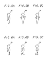
- the fundamental configuration (fundamental shape of man as the character in this embodiment is comprised of the arm parameter Q which is formed with three kinds of shapes (Figs. 5A, 5B and 5C) and the leg parameter R which is formed with three kinds of shapes (Figs. 6A, 6B and 6C).
- the arm parameter Q is expressed by ratio of three numerals (Q A : Q B : Q C )
- the leg parameter R is expressed by ratio of three numerals (R A : R B : R C )
- the movement parameter S is expressed by coordinates values in the lateral direction and which values fall in a range of 0 to 500.
- the ratio (Q A : Q B : Q C ) represents the mixing ratio for the shapes shown in Figs. 5A, 5B and 5C
- the ratio (R A : R B : R C ) represents the mixing ratio for shapes shown in Figs. 6A, 6B and 6C.
- the operator selects a series of timing points t10 to t14 along the time line T1, and determines values Q0 to Q4 (ratio of three numerals) of the arm parameter Q in response to these timing points t10 to t14
- the values Q0 to Q4 of the arm parameter Q correspond to figures 100 to 104 which show the motions of arms.
- the CPU 30 of the example of Fig. 3 performs the interpolation operation to calculate the values of the arm parameter Q, and the thus calculated values are stored in the area 9A of the memory 20.
- Fig. 4A the operator selects a series of timing points t10 to t14 along the time line T1, and determines values Q0 to Q4 (ratio of three numerals) of the arm parameter Q in response to these timing points t10 to t14
- the values Q0 to Q4 of the arm parameter Q correspond to figures 100 to 104 which show the motions of arms.
- the CPU 30 of the example of Fig. 3 performs the interpolation operation to calculate the values
- the operator selects a series of timing points t20 to t26 along the time line T2, and determines values R0 to R6 (ratio of three numerals) of the leg parameter R in response to these timing points t20 to t26.
- the values R0 to R6 of the leg parameter R correspond to figures 110 to 116 which show the motions of legs. Thereafter, values of leg parameter R at other timing points on the time line T2 are calculated by the interpolation operation and stored in the area 9B of the memory 20.
- the operator selects a series of timing points t30 to t34 along the time line T3, and determines values S0 to S4 of the movement parameter S in response to these timing points tsc to ts.
- the values S0 to S4 of the movement parameter S correspond to man's positions 120 to 124 on the display screen 6 of the image display apparatus 5.
- Values of the movement parameter S at other timing points on the time line T3 are calculated by the interpolation operation and stored in the area 9C of the memory 20.
- time lines T1, T2 and T3 shown in Fig. 4 are executed simultaneously. That is, the CPU 30 sequentially reads out the values of three parameters Q, R and S from the memory 20 in the units of frame period, and then calculates data of respective shapes stored in the memory 20 in response to the values of the above-described parameters to sequentially determine the entire shapes of man, that is, the character in the units of frame period. The thus determined entire shapes are sequentially displayed on the display screen 6 of the image display apparatus 5.
- the operator reduces an interval between the timing points t10, t11, ..., along the time T shown in Fig. 4A and once again determines values of the arm parameter Q in response to new timing points t10, t11, ..., but unlike the prior art, the parameters R and S of Figs. 4B and 4C need not be determined once again. In other words, the leg and movement parameters R and S need not be determined once again and only the arm parameter Q can be corrected, added or deleted. Similarly, if it is requested to move man from right to left on the display screen 6, the operator may change the value of the movement parameter S along the time line T3 shown in Fig. 4C. Therefore, according to this embodiment, the motion of a certain part of the man provided as the character can be corrected readily with ease. There is then the substantial advantage that the animation can be made efficiently.
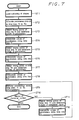
- n assumes the number of parameters to designate motions of character
- m assumes the number of time lines (m ⁇ n).
- step ST1 the operator loads on the memory 20 data of a plurality of shapes which are fundamental configurations of the character.
- n parameters U1 to U n are allocated to m time lines T1 to T m .
- the operator selects a plurality of timing points along the time line T1 and determines values of parameters corresponding to these selected timing points (in step ST3).
- the CPU 30 carries out the interpolation operation of the values of parameters along the time line T1 (in step ST4).
- step ST10 Similar processings along the time lines T2 to T m are executed from steps ST5 to ST8, and then in step ST9, the CPU 30 executes the processings along the time lines T1 to T m simultaneously, whereby the animation of character is displayed on the display screen 6.
- step ST10 the operator checks to see whether or not the motion of character is correct. To be more concrete, the operator checks to see whether or not the character moves in exactly the same correct way as those designated by the parameters of the respective time lines. If a YES is output at step ST10, the routine for producing animation is ended.
- step ST10 If it is determined in step ST10 that the motion of the character corresponding, for example, to a time line Ti (1 ⁇ i ⁇ m) is not correct, in step ST11, the operator selects again a plurality of new timing points along the time line Ti and determines values of parameters corresponding to those new timing points selected once again.
- step ST12 the CPU 30 performs the interpolation operation of the values of parameters along the time line Ti, and the processing of the CPU 30 returns to step ST9, wherein the processings for the time lines T1 to T m are simultaneously executed. Steps ST9 to ST12 are repeated until the motion of the character becomes correct.
- the motion of a certain part of the character may be corrected by correcting the corresponding time lines of the parameters for designating the motion, which makes it possible to produce the animation more efficiently.
- Another embodiment of the animation producing apparatus will be described, in which a synthesized parameter is generated on the basis of pre-determined parameters and parameters inputted by means of parameter input means and an input video image is transformed on the basis of the synthesized parameter, thereby an animation, which presents a desired change, being displayed in a real time fashion.
- a synthesized sound can be generated in response to an MIDI (i.e. musical instrument digital interface) signal and an input video image is transferred on the basis of parameters generated, thereby an animation being displayed in a real time fashion.
- MIDI i.e. musical instrument digital interface
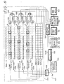
- Fig. 8 is a schematic block diagram showing the above-mentioned animation producing apparatus of the present invention.
- reference numeral 100 generally designates an animation producing apparatus which produces an animation in a real time fashion.
- data of fundamental configuration (fundamental shape) of a character is obtained by an image pickup device (not shown) and this data of fundamental shape is stored in an input video memory 102.
- the input video memory 102 stores therein three fundamental configurations (fundamental shapes) (see Figs. 6A, 6B and 6C) associated with the motion of legs of a character and three fundamental configurations (fundamental shapes) (see Figs. 5A, 5B and 5C) associated with the motion of arms of the character.
- a parameter memory 104 stores at its memories A, B and C a parameter Q associated with the motion of legs, a parameter R associated with the motion of arms, and a parameter S associated with the display position of the character, respectively.
- These parameters Q, R and S are sequentially allocated to time axes (i.e. expressed in the units of hour, minute, second and frame number) and stored in the memories A, B and C, respectively, whereby the fundamental shapes stored in the input video memory 102 are transferred and synthesized in response to the parameters Q, R and S, thereby displaying the character in a desirable motion.
- the operator designates desirable timing points T3, T8 and T c and also designates the motion of legs so that the shapes of the legs of the character displayed on a monitor 106 become identical with those of legs (Figs. 6A, 6B and 6C) stored in the input video memory 102 at the timing points T3, T8 and T c .
- parameters Q of values A3, A8 and Ac are stored in this memory A at timing points T3, T8 and T c .
- Parameters Q of values a1, a2, a4 to a7, a9 to ab, ad, ae, ... are generated from values A3, A8 and Ac of parameters Q at timing points T3, T8 and T c by the interpolation operation method and allocated to timing points before and after the timing points T3, T8 and T c .
- the operator designates desirable timing points T1, T8 and T c and also designates the motion of arms so that the shapes of the arms of the character displayed on the monitor 106 become identical with those of the arms (Figs. 5A, 5B and 5C) stored in the input video memory 102 at timing points T1, T8 and T e , resulting in the parameters R of values B1, B8 and Be being stored therein at timing points T1, T8 and T e .
- parameters R of values b2 to b7, b9 to bd, ... are generated from values B1, B8 and Be of the parameters R at timing points T1, T8 and T e by the interpolation operation method and allocated to timing points before and after the timing points T1, T8 and T e .
- the operator designates desirable timing points T4, T7 and T c and also designates display positions of characters displayed on the monitor 106 at timing points T4, T7 and T c , whereby the parameters S of values C4, C7 and Cc are stored therein at timing points T4, T7 and T c .
- parameters S of values c1 to c3, c5, c6, c8 to cb, cd, ce, ... are generated from values C4, C7 and Cc of the parameters S at timing points T4, T7 and T c by the interpolation operation method and allocated to timing points before and after the timing points T4, T7 and T c .
- a video converting and processing apparatus 110 is supplied with the parameters R, Q and S through weighting circuits 112A, 112B and 112C and adding circuits 114A, 114B and 114C. At that time, the parameters R, Q and S are supplied thereto in the sequential order in which these parameters are allocated to the time axes.
- the video converting and processing apparatus 110 is supplied with the shape data stored in the input video memory 102, and transforms the shapes of respective parts of the character expressed by the shape data in response to the values of the parameters R, Q and S.
- the video converting and processing apparatus 110 transforms video image, that is, transforms the shapes of the legs of the character so that the character may walk and gradually transforms the shapes of legs at timing points T1 and T2 until the transformed shape becomes identical with the shape (Fig. 6A) stored in the input video memory 102 at timing point T3.
- the video converting and processing apparatus 110 transforms the shape of character gradually during a period from timing points T3 to T7 and transforms the video image so that it may become identical with the shape (see Fig. 6B) stored in the input video memory 102 at timing point T8.
- the shape of the arm of the character is transformed so that the character may move the arms. That is, the shape is transformed so that the shape becomes identical with the shape (Fig. 5A) stored in the input video memory 102 at timing point T1, and is gradually changed from timing points T2 to T8 so that the shape becomes identical with the shape (Fig. 5B) stored in the input video memory 102 at timing point T8.
- the video converting and processing apparatus 110 synthesizes the shapes of the legs and arms transformed at timing points T1, T2, ... so as to form the entire configuration of character, and places the thus formed entire shape of the character at a position determined by the parameter S.
- An output video memory 116 temporarily stores therein a video image generated by the video converting and processing apparatus 110, and converts the same into a video signal. This video signal is fed to the monitor 106.
- the monitor 106 can display the animation which changes in the same way as is determined by the operator.
- a keyboard 120 supplies a sound source 122 with a signal S M (referred to hereinafter as an MIDI signal) according to the MIDI standards, whereby a speaker 124 is driven to emanate a synthesized sound in response to the key operation of the keyboard 120.
- a signal S M referred to hereinafter as an MIDI signal
- a filter 126 is formed of an operation and processing circuit and detects musical scale, stress and length of the synthesized sound emanated from the speaker 124 on the basis of the MIDI signal S M thereby to generate three parameters RR, RQ and RS on the basis of the detected results.
- the filter 126 At that time, the filter 126 generates the parameters RR, RQ and RS at cycles coincident with the time axes of the parameters R, Q and S respectively stored in the memories A, B and C and supplies these parameters RR, RQ and RS to weighting circuits 128A, 128B and 128C, respectively.
- the filter 126 generates the parameters RR, RQ and RS such that the values thereof are changed within the ranges corresponding to the parameters R, Q and S.
- the weighting circuits 128A, 128B and 128C are respectively supplied with the parameters RR, RQ and RS of values A1X, A2X, ..., B1X, B2X, ... and C1X, C2X, ... in response to the parameters R, Q and S when the player starts to play the keyboard 120.
- a coefficient control section 130 receives a control signal S CON which is generated from the keyboard 120 each time the player plays the keyboard 120, and supplies weighting coefficients K1, K3, K5 and K2, K4, K6 to the weighting circuits 112A, 112B, 112C and 128A, 128B, 128C in response to the control signal S CON , respectively.
- the weighting circuits 112A, 112B, 112C and 128A, 128B, 128C are adapted to weight the parameters R, Q, S and RR, RQ, RS in response to the weighting coefficients K1, K3, K5 and K2, K4, K6, respectively.
- the adding circuits 114A, 114B and 114C add weighted results of the weighting circuits 112A, 112B, 112C and 128A, 128B, 128C and supplies the added results to the video converting and processing circuit 110.
- the video converting and processing apparatus 110 is supplied with a synthesized parameter which results from synthesizing the parameters R, Q, S and the parameters RR, RQ, RS instead of the parameters R, Q and S, and transforms the shape of the character stored in the input video memory 102 on the basis of the synthesized parameter.
- the video converting and processing apparatus 110 can generate the synthesized parameter whose value is changed with the weighting coefficient from the coefficient control section 130 in accordance with the playing of the keyboard 120. Consequently, the animation can be produced by transforming the shape of character on the basis of the synthesized parameter, thereby producing the animation which is changed in response to the play of the keyboard 120.
- a video image signal formed by the video converting and processing circuit 110 is supplied through the output video memory 116 to the monitor 106, thereby being displayed.
- the animation producing apparatus 100 since the animation producing apparatus 100 generates the parameters RR, RQ and RS on the basis of the MIDI signal S M , the animation producing apparatus 100 can produce a so-called rhythm machine which can generate the MIDI signal S M in place of the keyboard 120 or the like, emanate a synthesized sound by further connecting thereto an arithmetic processing unit and produce an animation. Therefore, the animation producing apparatus of this embodiment can be used more conveniently.
- the synthesized parameters from the adding circuits 114A, 114B and 114C can be stored in buffer memories 132A, 132B and 132C, and the parameters R, Q and S stored in the memories A, B and C can be replaced with the synthesized parameters stored in the buffer memories 132A, 132B and 132C, if necessary.
- the parameter memory 104 includes parameter transfer means, though not shown, to transfer the synthesized parameters stored in the buffer memories 132A, 132B and 132C to the memories A, B and C. Thus, when the operator operates a predetermined key within the keyboard 120, the synthesized parameters are transferred to the memories A, B and C.
- the motion of animation is visually confirmed by means of the monitor 106 and, if necessary, the synthesized parameters used to produce that animation can be stored in the memories A, B and C.
- the input video memory 102 constructs the input video memory in which a plurality of fundamental shapes are stored
- the memories A, B and C construct main memories in which the parameters R, Q and S used to designate the motion of animation are sequentially stored in a time series fashion.
- the fundamental shape data of the character picked-up by the camera means is stored in the input video memory 102.
- the parameters R, Q and S presenting the shapes of legs and arms of the character and the display position of the character are allocated to the time axes and area stored in the memories A, B and C, respectively.
- the parameters RR, RQ and RS corresponding to the parameters R, Q and S are sequentially generated from the filter 126 in response to the MIDI signal S M from the keyboard 120. Then, these parameters RR, RQ and RS are respectively weighted by the weighting circuits 128A, 128B and 128C in response to the operation of the player.
- the parameters R, Q and S stored in the memories A, B and C are respectively weighted by the weighting circuits 112A, 112B and 112C, and the weighted results of the weighting circuits 112A, 128A; 128B; and 112C, 128C are added by the adding circuits 114A, 114B and 114C, respectively.
- the adding circuits 114A, 114B and 114C can derive the synthesized parameters whose values are changed in accordance with the playing of the keyboard 120. Then, the video converting and processing apparatus 110 transforms the fundamental shapes of the respective parts of the character stored in the input video memory 102 on the basis of the synthesized parameters.
- Transformed shapes of the respective parts of the character are synthesized by the video converting and processing apparatus 110 thereby to form the entire shape of the character. Then, the entire shape of the character is placed at the display position determined by the parameter S, thereby obtaining in a real time manner an animation whose motion is changed in response to the operation of the keyboard 120.
- the synthesized sound generated by the sound source 122 is emanated from the speaker 124 and the animation which is changed in accordance with the playing of the keyboard 120 in a real time manner can be displayed on the monitor 106.
- the parameters RR, RQ and RS can be generated on the basis of the MIDI signals from these apparatus.
- the present invention is not limited thereto and various kinds of signals other than the MIDI signal can be widely applied to the present invention.
- parameters are formed on the basis of natural sound and the like recorded on a tape of a tape recorder or the like, it is possible to produce an animation whose motion is changed with the natural sound.
- the present invention is not limited thereto and the present invention can be widely applied to the cases such as when the direction of the character is designated while animations are produed or when a video image except character, for example, man's look is changed.
- the synthesized parameters are formed on the basis of the pre-determined parameters and the parameters inputted by means of the parameter input means and the input video image is transformed in response to the synthesized parameters, it is possible to display on the monitor animations which present desirable changes in a real time fashion.
Abstract
Description
- The present invention generally relates to animation producing apparatus for producing animations and, more particularly, is directed to an animation producing apparatus which produces an animation by using a plurality set of parameters and a plurality set of fundamental shapes.
- When an animation of a predetermined character is produced by computer graphics, data of fundamental configuration (i.e. fundamental shape) of the character are inputted and motions of respective parts of the character are given by values of respective parameters. Then, values of all parameters are gradually changed along a certain time axis, whereby the character can be moved in a desirable fashion. The time axis is what might be called a time line and the unit of the time line is, by way of example, [hour: minute: second: frame number].
- Fig. 1 shows a conventional animation producing apparatus which utilizes computer graphics.
- In Fig. 1,
reference numeral 1 designates a keyboard, 2 a video image input apparatus such as a digitizer or the like, 3 a central processing unit (CPU), 4 a memory such as a random access memory (RAM), magnetic disc apparatus or the like, and 5 a video image display apparatus such as a cathode ray tube (CRT) and so on. Data of a fundamental configuration (i.e. fundamental shapes of a predetermined character are stored in thememory 4 from thekeyboard 1 and the videoimage input apparatus 2 through theCPU 3. The data of the fundamental shape of the character itself may be generated by an operation of the computer (see U.S. Pat. No. 4,791,581). - If the character is, for example, man, man's motions can be expressed by a parameter group P which is formed of three parameters (i.e. parameter for designating waving of arms, parameter for designating motion of legs and parameter designating moving amount of character in the lateral direction).
- More specifically, as shown in Fig. 2, the operator operates the
keyboard 1 to set in thememory 4 values P₀, P₁ and P₂ of the parameter group P at timing points t₀, t₁ and t₂ in one time line T. Then, theCPU 3 performs interpolation operation to generate values of parameter group P between timing points t₀ and t₁ and between timing points t₁ and t₂ in the units of frame period, whereby a value of parameter group Px at, for example, timing point tx (t₀ < tx < t₁) becomes an intermediate value between the values P₀ and P₁. Assuming thatcharacters display picture screen 6 of the videoimage display apparatus 5 in response to the values P₀, P₁ and P₂ of the parameter group P, the shape of thecharacter 7₀ is gradually changed to that of thecharacter 7₁ on thedisplay picture screen 6 from timing points t₀ to t₁, and the shape ofcharacter 7₁ is gradually changed to that ofcharacter 7₂ on thedisplay picture screen 6 from timing points t₁ to t₂. - However, as described above, the operator must simultaneously determine all values of parameters for instructing the motion of arms, the motion of legs and the moving amount of the character in the lateral direction at timing points t₀, t₁ and t₂ which are selected by the operator along one time line T. Accordingly, when the operator wants to change only the motion of arm of character after viewing the animations, the operator has to change parameter for designating the motion of arm along the time line T and must also determine values of all parameters at each time point one more time. Therefore, the motion of a certain part of character cannot be changed efficiently.
- Accordingly, it is an object of the present invention to provide an improved animation producing apparatus in which the aforementioned shortcomings and disadvantages of the prior art can be substantially eliminated.
- More specifically, it is an object of the present invention to provide an animation producing apparatus in which a motion of a certain part of character can be changed with ease.
- It is another object of the present invention to provide an animation producing apparatus in which a motion of character can be fine-adjusted.
- It is a further object of the present invention to provide an animation producing apparatus in which an animation can be moved in response to a synthesized sound in a real time fashion.
- According to a first aspect of the present invention, an animation producing apparatus for producing an animation on the basis of fundamental shapes and parameters is comprised of an input device for inputting a plurality set of fundamental shapes and a plurality set of parameters corresponding to the plurality set of fundamental shapes, a memory for storing therein the plurality set of fundamental shapes and the plurality set of parameters, values of the plurality set of parameters stored in the memory being independently varied, added or deleted by the input device, a computing circuit for producing an animation by an interpolation on the basis of the plurality set of fundamental shapes and the plurality set of parameters read-out from the memory, and a display for displaying thereon the animation produced by the computing circuit.
- As a second aspect of the present invention, an animation producing apparatus for producing an animation on the basis of fundamental shapes and parameters is comprised of a first memory for storing therein a plurality set of fundamental shapes, a second memory for storing a plurality set of first parameters corresponding to the plurality set of fundamental shapes, an input device for inputting a plurality set of second parameters corresponding to the plurality set of fundamental shapes, a plurality of adders for adding the plurality of first parameters read-out from the second memory and the plurality of second parameters inputted by the input device with predetermined ratios thereby to generate a plurality set of third parameters, an image processor for producing an animation by an interpolation process on the basis of the plurality set of fundamental shapes read-out from the first memory and the plurality set of third parameters generated from the plurality of adders, and a display for displaying the animation produced by the image processor.
- In accordance with a third aspect of the present invention, an animation producing apparatus for producing an animation on the basis of fundamental shapes and parameters is comprised of a memory for storing a plurality set of fundamental shapes, an MIDI signal generating circuit for generating an MIDI signal, a parameter generating circuit for generating a plurality set of parameters corresponding to the plurality set of fundamental shapes on the basis of the MIDI signal, an image processor for producing an animation by an interpolation process on the basis of the plurality set of fundamental shapes read-out from the memory and the plurality set of parameters generated from the parameter generating circuit, a display for displaying thereon the animation produced by the image processor, and a synthesized sound generating circuit for generating a synthesized sound on the basis of the MIDI signal.
- The preceding, and other objects, features and advantages of the present invention will be apparent in the following detailed description of illustrative embodiments to be taken in conjunction with the accompanying drawings, in which like reference numerals are used to identify the same or similar parts in the several views.
-
- Fig. 1 is a schematic diagram showing an example of a conventional animation producing apparatus;
- Fig. 2 is a schematic representation used to explain a time axis of parameters in the conventional animation producing apparatus of Fig. 1;
- Fig. 3 is a schematic diagram showing a first embodiment of an animation producing apparatus according to the present invention;
- Figs. 4A - 4C are schematic diagrams used to explain time axes of parameters in the animation producing apparatus of the present invention shown in Fig. 3, respectively;
- Figs. 5A - 5C are schematic diagrams showing fundamental shapes for arms used in the animation producing apparatus of Fig. 3, respectively;
- Figs. 6A - 6C are schematic diagrams showing fundamental shapes for legs used in the animation producing apparatus of Fig. 3, respectively;
- Fig. 7 is a flow chart to which reference will be made in explaining routine in which an animation is produced by the animation producing apparatus of Fig. 3; and
- Fig. 8 is a block diagram showing a second embodiment of the animation producing apparatus according to the present invention.
- Referring to the drawings in detail, and initially to Figs. 3 to 6, a first embodiment of the animation producing apparatus according to the present invention will be described hereinafter.
- As shown in Fig. 3, in the animation producing apparatus of the present invention, a storage area of a
memory 20 is separated to provide anarea 8 in which data of fundamental configuration (referred to hereinafter as "fundamental shape") of a character are stored, anarea 9A in which values of parameter Q along a time line T₁ are stored in the units of frame period, an area 9B in which values of parameter R along a time line T₂ are stored in the units of frame period and anarea 9C in which values of parameter S along a time line T₃ are stored in the units of frame period. Flags are added to theseareas 9A to 9C in order to indicate the time lines T₁ to T₃, respectively. - In this embodiment, the present invention is applied to an animation in which a character or man performs predetermined operations. In this embodiment, there are provided three parameters, i.e. parameter (arm parameter) Q used to designate motion of man,s arms, parameter leg parameter) R used to designate motion of man,s legs and parameter (movement parameter) S used to designate moving amount of man or character in the lateral direction.
- As shown in Fig. 4, time axes i.e. time lines) T₁, T₂ and T₃ are assigned to these three parameters Q, R and S, respectively. The fundamental configuration (fundamental shape of man as the character in this embodiment is comprised of the arm parameter Q which is formed with three kinds of shapes (Figs. 5A, 5B and 5C) and the leg parameter R which is formed with three kinds of shapes (Figs. 6A, 6B and 6C). The arm parameter Q is expressed by ratio of three numerals (QA : QB : QC, the leg parameter R is expressed by ratio of three numerals (RA : RB : RC), and the movement parameter S is expressed by coordinates values in the lateral direction and which values fall in a range of 0 to 500. In that case, the ratio (QA : QB : QC) represents the mixing ratio for the shapes shown in Figs. 5A, 5B and 5C, and the ratio (RA : RB : RC) represents the mixing ratio for shapes shown in Figs. 6A, 6B and 6C.
- A process for producing an animation according to this embodiment will be described with reference to Figs. 4A - 4C.
- As shown in Fig. 4A, the operator selects a series of timing points t₁₀ to t₁₄ along the time line T₁, and determines values Q₀ to Q₄ (ratio of three numerals) of the arm parameter Q in response to these timing points t₁₀ to t₁₄ The values Q₀ to Q₄ of the arm parameter Q correspond to figures 10₀ to 10₄ which show the motions of arms. Then, at respective timing points of frame period except the timing points t₁₀ to t₁₄ along the time line T₁, the
CPU 30 of the example of Fig. 3 performs the interpolation operation to calculate the values of the arm parameter Q, and the thus calculated values are stored in thearea 9A of thememory 20. Then, as shown in Fig. 4B, the operator selects a series of timing points t₂₀ to t₂₆ along the time line T₂, and determines values R₀ to R₆ (ratio of three numerals) of the leg parameter R in response to these timing points t₂₀ to t₂₆. The values R₀ to R₆ of the leg parameter R correspond to figures 11₀ to 11₆ which show the motions of legs. Thereafter, values of leg parameter R at other timing points on the time line T₂ are calculated by the interpolation operation and stored in the area 9B of thememory 20. - Further, as shown in Fig. 4C, the operator selects a series of timing points t₃₀ to t₃₄ along the time line T₃, and determines values S₀ to S₄ of the movement parameter S in response to these timing points tsc to ts.. The values S₀ to S₄ of the movement parameter S correspond to man's
positions 12₀ to 12₄ on thedisplay screen 6 of theimage display apparatus 5. Values of the movement parameter S at other timing points on the time line T₃ are calculated by the interpolation operation and stored in thearea 9C of thememory 20. - Finally, the time lines T₁, T₂ and T₃ shown in Fig. 4 are executed simultaneously. That is, the
CPU 30 sequentially reads out the values of three parameters Q, R and S from thememory 20 in the units of frame period, and then calculates data of respective shapes stored in thememory 20 in response to the values of the above-described parameters to sequentially determine the entire shapes of man, that is, the character in the units of frame period. The thus determined entire shapes are sequentially displayed on thedisplay screen 6 of theimage display apparatus 5. - In this embodiment, if it is requested that the character, i.e. man moves, for example, arms more quickly, the operator reduces an interval between the timing points t₁₀, t₁₁, ..., along the time T shown in Fig. 4A and once again determines values of the arm parameter Q in response to new timing points t₁₀, t₁₁, ..., but unlike the prior art, the parameters R and S of Figs. 4B and 4C need not be determined once again. In other words, the leg and movement parameters R and S need not be determined once again and only the arm parameter Q can be corrected, added or deleted. Similarly, if it is requested to move man from right to left on the
display screen 6, the operator may change the value of the movement parameter S along the time line T₃ shown in Fig. 4C. Therefore, according to this embodiment, the motion of a certain part of the man provided as the character can be corrected readily with ease. There is then the substantial advantage that the animation can be made efficiently. - A routine in which the procedure for producing an animation in the examples of Figs. 4A - 4C is generalized will be described with reference to Fig. 7. In that case, n assumes the number of parameters to designate motions of character, and m assumes the number of time lines (m ≦ n).
- Referring to Fig. 7, in step ST1, the operator loads on the
memory 20 data of a plurality of shapes which are fundamental configurations of the character. At step ST2, n parameters U₁ to Un are allocated to m time lines T₁ to Tm. Then, the operator selects a plurality of timing points along the time line T₁ and determines values of parameters corresponding to these selected timing points (in step ST3). Thereafter, theCPU 30 carries out the interpolation operation of the values of parameters along the time line T₁ (in step ST4). - Similar processings along the time lines T₂ to Tm are executed from steps ST5 to ST8, and then in step ST9, the
CPU 30 executes the processings along the time lines T₁ to Tm simultaneously, whereby the animation of character is displayed on thedisplay screen 6. In the next decision step ST10, the operator checks to see whether or not the motion of character is correct. To be more concrete, the operator checks to see whether or not the character moves in exactly the same correct way as those designated by the parameters of the respective time lines. If a YES is output at step ST10, the routine for producing animation is ended. - If it is determined in step ST10 that the motion of the character corresponding, for example, to a time line Ti (1 ≦ i ≦ m) is not correct, in step ST11, the operator selects again a plurality of new timing points along the time line Ti and determines values of parameters corresponding to those new timing points selected once again. In step ST12, the
CPU 30 performs the interpolation operation of the values of parameters along the time line Ti, and the processing of theCPU 30 returns to step ST9, wherein the processings for the time lines T₁ to Tm are simultaneously executed. Steps ST9 to ST12 are repeated until the motion of the character becomes correct. - Also in this embodiment of Fig. 7, the motion of a certain part of the character may be corrected by correcting the corresponding time lines of the parameters for designating the motion, which makes it possible to produce the animation more efficiently.
- According to the above embodiment of the present invention, since the motion of a certain part of character can be corrected with ease by correcting a series of timing points of a certain group within a plurality of groups and by correcting values of parameters corresponding to a series of timing points, it is possible to produce an animation more efficiently.
- Another embodiment of the animation producing apparatus according to the present invention will be described, in which a synthesized parameter is generated on the basis of pre-determined parameters and parameters inputted by means of parameter input means and an input video image is transformed on the basis of the synthesized parameter, thereby an animation, which presents a desired change, being displayed in a real time fashion. A further embodiment of the animation producing apparatus according to the present invention will be described, in which a synthesized sound can be generated in response to an MIDI (i.e. musical instrument digital interface) signal and an input video image is transferred on the basis of parameters generated, thereby an animation being displayed in a real time fashion.
- Fig. 8 is a schematic block diagram showing the above-mentioned animation producing apparatus of the present invention.
- In Fig. 8,
reference numeral 100 generally designates an animation producing apparatus which produces an animation in a real time fashion. - In the
animation producing apparatus 100, data of fundamental configuration (fundamental shape) of a character is obtained by an image pickup device (not shown) and this data of fundamental shape is stored in aninput video memory 102. - As shown in Figs. 5 and 6, the
input video memory 102 stores therein three fundamental configurations (fundamental shapes) (see Figs. 6A, 6B and 6C) associated with the motion of legs of a character and three fundamental configurations (fundamental shapes) (see Figs. 5A, 5B and 5C) associated with the motion of arms of the character. - In response thereto, a
parameter memory 104 stores at its memories A, B and C a parameter Q associated with the motion of legs, a parameter R associated with the motion of arms, and a parameter S associated with the display position of the character, respectively. - These parameters Q, R and S are sequentially allocated to time axes (i.e. expressed in the units of hour, minute, second and frame number) and stored in the memories A, B and C, respectively, whereby the fundamental shapes stored in the
input video memory 102 are transferred and synthesized in response to the parameters Q, R and S, thereby displaying the character in a desirable motion. - In the memory A in which the parameter R is stored, the operator designates desirable timing points T₃, T₈ and Tc and also designates the motion of legs so that the shapes of the legs of the character displayed on a
monitor 106 become identical with those of legs (Figs. 6A, 6B and 6C) stored in theinput video memory 102 at the timing points T₃, T₈ and Tc. Thus, parameters Q of values A3, A8 and Ac are stored in this memory A at timing points T₃, T₈ and Tc. - Parameters Q of values a1, a2, a4 to a7, a9 to ab, ad, ae, ... are generated from values A3, A8 and Ac of parameters Q at timing points T₃, T₈ and Tc by the interpolation operation method and allocated to timing points before and after the timing points T₃, T₈ and Tc.
- Similarly, in the memory B in which the parameters R are stored, the operator designates desirable timing points T₁, T₈ and Tc and also designates the motion of arms so that the shapes of the arms of the character displayed on the
monitor 106 become identical with those of the arms (Figs. 5A, 5B and 5C) stored in theinput video memory 102 at timing points T₁, T₈ and Te, resulting in the parameters R of values B1, B8 and Be being stored therein at timing points T₁, T₈ and Te. - Further, parameters R of values b2 to b7, b9 to bd, ... are generated from values B1, B8 and Be of the parameters R at timing points T₁, T₈ and Te by the interpolation operation method and allocated to timing points before and after the timing points T₁, T₈ and Te.
- In the memory C in which the parameter S are stored, the operator designates desirable timing points T₄, T₇ and Tc and also designates display positions of characters displayed on the
monitor 106 at timing points T₄, T₇ and Tc, whereby the parameters S of values C4, C7 and Cc are stored therein at timing points T₄, T₇ and Tc. - Furthermore, parameters S of values c1 to c3, c5, c6, c8 to cb, cd, ce, ... are generated from values C4, C7 and Cc of the parameters S at timing points T₄, T₇ and Tc by the interpolation operation method and allocated to timing points before and after the timing points T₄, T₇ and Tc.
- A video converting and
processing apparatus 110 is supplied with the parameters R, Q and S throughweighting circuits circuits - Further, the video converting and
processing apparatus 110 is supplied with the shape data stored in theinput video memory 102, and transforms the shapes of respective parts of the character expressed by the shape data in response to the values of the parameters R, Q and S. - More specifically, the video converting and
processing apparatus 110 transforms video image, that is, transforms the shapes of the legs of the character so that the character may walk and gradually transforms the shapes of legs at timing points T₁ and T₂ until the transformed shape becomes identical with the shape (Fig. 6A) stored in theinput video memory 102 at timing point T₃. - Further, the video converting and
processing apparatus 110 transforms the shape of character gradually during a period from timing points T₃ to T₇ and transforms the video image so that it may become identical with the shape (see Fig. 6B) stored in theinput video memory 102 at timing point T₈. - The shape of the arm of the character is transformed so that the character may move the arms. That is, the shape is transformed so that the shape becomes identical with the shape (Fig. 5A) stored in the
input video memory 102 at timing point T₁, and is gradually changed from timing points T₂ to T₈ so that the shape becomes identical with the shape (Fig. 5B) stored in theinput video memory 102 at timing point T₈. - The video converting and
processing apparatus 110 synthesizes the shapes of the legs and arms transformed at timing points T₁, T₂, ... so as to form the entire configuration of character, and places the thus formed entire shape of the character at a position determined by the parameter S. - An
output video memory 116 temporarily stores therein a video image generated by the video converting andprocessing apparatus 110, and converts the same into a video signal. This video signal is fed to themonitor 106. - Therefore, the
monitor 106 can display the animation which changes in the same way as is determined by the operator. - A
keyboard 120 supplies asound source 122 with a signal SM (referred to hereinafter as an MIDI signal) according to the MIDI standards, whereby aspeaker 124 is driven to emanate a synthesized sound in response to the key operation of thekeyboard 120. - A
filter 126 is formed of an operation and processing circuit and detects musical scale, stress and length of the synthesized sound emanated from thespeaker 124 on the basis of the MIDI signal SM thereby to generate three parameters RR, RQ and RS on the basis of the detected results. - At that time, the
filter 126 generates the parameters RR, RQ and RS at cycles coincident with the time axes of the parameters R, Q and S respectively stored in the memories A, B and C and supplies these parameters RR, RQ and RS toweighting circuits - Further, at that time, the
filter 126 generates the parameters RR, RQ and RS such that the values thereof are changed within the ranges corresponding to the parameters R, Q and S. - Therefore, the
weighting circuits keyboard 120. - A
coefficient control section 130 receives a control signal SCON which is generated from thekeyboard 120 each time the player plays thekeyboard 120, and supplies weighting coefficients K1, K3, K5 and K2, K4, K6 to theweighting circuits - The
weighting circuits - The adding
circuits weighting circuits processing circuit 110. - Thus, when the player plays the
keyboard 120, the video converting andprocessing apparatus 110 is supplied with a synthesized parameter which results from synthesizing the parameters R, Q, S and the parameters RR, RQ, RS instead of the parameters R, Q and S, and transforms the shape of the character stored in theinput video memory 102 on the basis of the synthesized parameter. - Therefore, the video converting and
processing apparatus 110 can generate the synthesized parameter whose value is changed with the weighting coefficient from thecoefficient control section 130 in accordance with the playing of thekeyboard 120. Consequently, the animation can be produced by transforming the shape of character on the basis of the synthesized parameter, thereby producing the animation which is changed in response to the play of thekeyboard 120. A video image signal formed by the video converting andprocessing circuit 110 is supplied through theoutput video memory 116 to themonitor 106, thereby being displayed. - By switching the weighting coefficients, it is possible to obtain an animation in which the motion following the playing of the
keyboard 120 is subordinated to the motions pre-determined in the memories A, B and C or conversely an animation in which the motions pre-determined in the memories A, B and C are subordinated to the motion following the playing of thekeyboard 120, resulting in the animation being formed in a wide variety of expression styles. - Further, since the
animation producing apparatus 100 generates the parameters RR, RQ and RS on the basis of the MIDI signal SM, theanimation producing apparatus 100 can produce a so-called rhythm machine which can generate the MIDI signal SM in place of thekeyboard 120 or the like, emanate a synthesized sound by further connecting thereto an arithmetic processing unit and produce an animation. Therefore, the animation producing apparatus of this embodiment can be used more conveniently. - Further, in this embodiment, the synthesized parameters from the adding
circuits buffer memories buffer memories - The
parameter memory 104 includes parameter transfer means, though not shown, to transfer the synthesized parameters stored in thebuffer memories keyboard 120, the synthesized parameters are transferred to the memories A, B and C. - Therefore, the motion of animation is visually confirmed by means of the
monitor 106 and, if necessary, the synthesized parameters used to produce that animation can be stored in the memories A, B and C. - Accordingly, improvised animation can be reproduced by updating the contents of the memories A, B and C.
- Further, if the animation producing apparatus of the present invention is applied to the correcting work of animation, then this correcting work can be carried out with ease.
- As described above, according to this embodiment, while the
input video memory 102 constructs the input video memory in which a plurality of fundamental shapes are stored, the memories A, B and C construct main memories in which the parameters R, Q and S used to designate the motion of animation are sequentially stored in a time series fashion. - In the
animation producing apparatus 100 of the present invention, as described above, the fundamental shape data of the character picked-up by the camera means is stored in theinput video memory 102. - When the operator designates timing points and the motions of respective parts of the character, the parameters R, Q and S presenting the shapes of legs and arms of the character and the display position of the character are allocated to the time axes and area stored in the memories A, B and C, respectively.
- When the player plays the
keyboard 120 after the above preliminary processing, the parameters RR, RQ and RS corresponding to the parameters R, Q and S are sequentially generated from thefilter 126 in response to the MIDI signal SM from thekeyboard 120. Then, these parameters RR, RQ and RS are respectively weighted by theweighting circuits - Simultaneously, the parameters R, Q and S stored in the memories A, B and C are respectively weighted by the
weighting circuits weighting circuits circuits - Therefore, the adding
circuits keyboard 120. Then, the video converting andprocessing apparatus 110 transforms the fundamental shapes of the respective parts of the character stored in theinput video memory 102 on the basis of the synthesized parameters. - Transformed shapes of the respective parts of the character are synthesized by the video converting and
processing apparatus 110 thereby to form the entire shape of the character. Then, the entire shape of the character is placed at the display position determined by the parameter S, thereby obtaining in a real time manner an animation whose motion is changed in response to the operation of thekeyboard 120. - At that time, the synthesized sound generated by the
sound source 122 is emanated from thespeaker 124 and the animation which is changed in accordance with the playing of thekeyboard 120 in a real time manner can be displayed on themonitor 106. - By using other playing apparatus and arithmetic processing apparatus instead of the thus arranged
keyboard 120, the parameters RR, RQ and RS can be generated on the basis of the MIDI signals from these apparatus. - While the parameters are generated on the basis of the MIDI signal as described above, the present invention is not limited thereto and various kinds of signals other than the MIDI signal can be widely applied to the present invention.
- In that case, if parameters are generated on the basis of input signals from other apparatus such as a mouse, a digitizer and so on, it is possible to produce an animation whose motion is changed in response to the operation of the digitizer, the mouse or the like.
- Further, if parameters are formed on the basis of natural sound and the like recorded on a tape of a tape recorder or the like, it is possible to produce an animation whose motion is changed with the natural sound.
- While the legs, arms and display position of the character are designated by means of the parameters to produce animations in the above-described embodiment, the present invention is not limited thereto and the present invention can be widely applied to the cases such as when the direction of the character is designated while animations are produed or when a video image except character, for example, man's look is changed.
- According to the above-described invention, since the synthesized parameters are formed on the basis of the pre-determined parameters and the parameters inputted by means of the parameter input means and the input video image is transformed in response to the synthesized parameters, it is possible to display on the monitor animations which present desirable changes in a real time fashion.
- Furthermore, since the synthesized sound is emanated in response to the MIDI signal and the input video image is transformed on the basis of the parameters generated, an animation which presents a desirable change in response to the synthesized sound can be dislayed on the monitor in a real time fashion.
- Having described preferred embodiments of the invention with reference to the accompanying drawings, it is to be understood that the invention is not limited to those precise embodiments and that various changes and modifications thereof could be effected by one skilled in the art without departing from the spirit or scope of the novel concepts of the invention as defined in the appended claims.
Claims (10)
Applications Claiming Priority (4)
| Application Number | Priority Date | Filing Date | Title |
|---|---|---|---|
| JP1295756A JP2861142B2 (en) | 1989-11-14 | 1989-11-14 | Animation creation equipment |
| JP295756/89 | 1989-11-14 | ||
| JP10861/90 | 1990-01-21 | ||
| JP2010861A JP2943201B2 (en) | 1990-01-21 | 1990-01-21 | Image creation apparatus and method |
Publications (3)
| Publication Number | Publication Date |
|---|---|
| EP0428164A2 true EP0428164A2 (en) | 1991-05-22 |
| EP0428164A3 EP0428164A3 (en) | 1993-01-13 |
| EP0428164B1 EP0428164B1 (en) | 1997-03-26 |
Family
ID=26346212
Family Applications (1)
| Application Number | Title | Priority Date | Filing Date |
|---|---|---|---|
| EP90121824A Expired - Lifetime EP0428164B1 (en) | 1989-11-14 | 1990-11-14 | Animation producing apparatus |
Country Status (4)
| Country | Link |
|---|---|
| US (1) | US5214758A (en) |
| EP (1) | EP0428164B1 (en) |
| KR (1) | KR0154976B1 (en) |
| DE (1) | DE69030298T2 (en) |
Cited By (7)
| Publication number | Priority date | Publication date | Assignee | Title |
|---|---|---|---|---|
| EP0589658A2 (en) * | 1992-09-21 | 1994-03-30 | Matsushita Electric Industrial Co., Ltd. | Superimposing of graphic data with graphic parameter store |
| NL1000679C2 (en) * | 1995-06-28 | 1996-12-31 | Arie Van Wieringen Video Film | Motion editor / assembly unit. |
| WO1999017259A1 (en) * | 1997-09-29 | 1999-04-08 | Intergraph Corporation | Automatic frame accumulator |
| US5977965A (en) * | 1997-09-29 | 1999-11-02 | Intergraph Corporation | Automatic frame accumulator |
| EP0962887A2 (en) * | 1998-06-03 | 1999-12-08 | Konami Co., Ltd. | Method of and apparatus for controlling the display of a game image |
| EP1145745A2 (en) * | 2000-01-24 | 2001-10-17 | Konami Corporation | Video game device, character action setting method in video game, and computer-readable recording medium storing character action setting program |
| WO2002062535A2 (en) * | 2001-02-07 | 2002-08-15 | Giovanni Pioggia | Method for controlling an articulated and/or deformable mechanical system and its applications |
Families Citing this family (69)
| Publication number | Priority date | Publication date | Assignee | Title |
|---|---|---|---|---|
| US5969704A (en) * | 1990-09-04 | 1999-10-19 | Mikohn Gaming Corporation | Configurable led matrix display |
| JP3093247B2 (en) * | 1990-09-21 | 2000-10-03 | 株式会社東芝 | Presentation support environment system |
| AU9015891A (en) * | 1990-11-30 | 1992-06-25 | Cambridge Animation Systems Limited | Animation |
| US5459829A (en) * | 1991-02-13 | 1995-10-17 | Kabushiki Kaisha Toshiba | Presentation support system |
| US5613056A (en) * | 1991-02-19 | 1997-03-18 | Bright Star Technology, Inc. | Advanced tools for speech synchronized animation |
| US5459830A (en) * | 1991-07-22 | 1995-10-17 | Sony Corporation | Animation data index creation drawn from image data sampling composites |
| JPH06101018B2 (en) * | 1991-08-29 | 1994-12-12 | インターナショナル・ビジネス・マシーンズ・コーポレイション | Search of moving image database |
| US5634133A (en) * | 1992-01-17 | 1997-05-27 | Compaq Computer Corporation | Constraint based graphics system |
| US5388841A (en) | 1992-01-30 | 1995-02-14 | A/N Inc. | External memory system having programmable graphics processor for use in a video game system or the like |
| CA2074388C (en) * | 1992-01-30 | 2003-01-14 | Jeremy E. San | Programmable graphics processor having pixel to character conversion hardware for use in a video game system or the like |
| US5357604A (en) * | 1992-01-30 | 1994-10-18 | A/N, Inc. | Graphics processor with enhanced memory control circuitry for use in a video game system or the like |
| US5706417A (en) * | 1992-05-27 | 1998-01-06 | Massachusetts Institute Of Technology | Layered representation for image coding |
| CA2100893A1 (en) * | 1992-08-06 | 1994-02-07 | Michael E. Stickney | Interactive computerized witness interrogation recording tool |
| FR2695230B1 (en) * | 1992-08-26 | 1994-11-04 | Cuadros Isabelle | Process for creating animated images. |
| US5450540A (en) * | 1992-12-16 | 1995-09-12 | Apple Computer, Inc. | Graphical interface for interacting constrained actors |
| US5500933A (en) * | 1993-04-28 | 1996-03-19 | Canon Information Systems, Inc. | Display system which displays motion video objects combined with other visual objects |
| US6108001A (en) * | 1993-05-21 | 2000-08-22 | International Business Machines Corporation | Dynamic control of visual and/or audio presentation |
| JP3345473B2 (en) * | 1993-08-03 | 2002-11-18 | 株式会社日立製作所 | Animation generation method |
| US5621431A (en) * | 1994-04-29 | 1997-04-15 | Atari Games Corporation | Animation system having variable video display rate |
| US5574798A (en) * | 1994-08-03 | 1996-11-12 | International Business Machines Corporation | Visual presentation system which determines length of time to present each slide or transparency |
| US5767845A (en) * | 1994-08-10 | 1998-06-16 | Matsushita Electric Industrial Co. | Multi-media information record device, and a multi-media information playback device |
| US5613093A (en) * | 1994-10-12 | 1997-03-18 | Kolb; George P. | Apparatus and method for drill design |
| EP0712097A2 (en) * | 1994-11-10 | 1996-05-15 | Matsushita Electric Industrial Co., Ltd. | Method and system for manipulating motion units for computer articulated figure animation |
| US5717468A (en) * | 1994-12-02 | 1998-02-10 | International Business Machines Corporation | System and method for dynamically recording and displaying comments for a video movie |
| US5689682A (en) * | 1995-03-07 | 1997-11-18 | Dynamix, Inc. | Computerized flight simulation control sampling and production system and method |
| US5734794A (en) * | 1995-06-22 | 1998-03-31 | White; Tom H. | Method and system for voice-activated cell animation |
| US5731819A (en) * | 1995-07-18 | 1998-03-24 | Softimage | Deformation of a graphic object to emphasize effects of motion |
| GB9525047D0 (en) * | 1995-12-07 | 1996-02-07 | Philips Electronics Nv | Virtual body control device |
| US7012607B1 (en) * | 1996-01-05 | 2006-03-14 | Microsoft Corporation | Method and system for generating user-interface output sequences |
| US5970504A (en) * | 1996-01-31 | 1999-10-19 | Mitsubishi Denki Kabushiki Kaisha | Moving image anchoring apparatus and hypermedia apparatus which estimate the movement of an anchor based on the movement of the object with which the anchor is associated |
| US6144972A (en) * | 1996-01-31 | 2000-11-07 | Mitsubishi Denki Kabushiki Kaisha | Moving image anchoring apparatus which estimates the movement of an anchor based on the movement of the object with which the anchor is associated utilizing a pattern matching technique |
| JP2000512039A (en) | 1996-03-15 | 2000-09-12 | ザパ デジタル アーツ リミテッド | Programmable computer graphic objects |
| US5852450A (en) * | 1996-07-11 | 1998-12-22 | Lamb & Company, Inc. | Method and apparatus for processing captured motion data |
| JPH1097641A (en) * | 1996-09-20 | 1998-04-14 | Sanyo Electric Co Ltd | Method and device for generating moving image |
| US5999194A (en) * | 1996-11-14 | 1999-12-07 | Brunelle; Theodore M. | Texture controlled and color synthesized animation process |
| US6088042A (en) * | 1997-03-31 | 2000-07-11 | Katrix, Inc. | Interactive motion data animation system |
| US6057859A (en) * | 1997-03-31 | 2000-05-02 | Katrix, Inc. | Limb coordination system for interactive computer animation of articulated characters with blended motion data |
| US6191798B1 (en) * | 1997-03-31 | 2001-02-20 | Katrix, Inc. | Limb coordination system for interactive computer animation of articulated characters |
| US6184899B1 (en) * | 1997-03-31 | 2001-02-06 | Treyarch Invention, L.L.C. | Articulated figure animation using virtual actuators to simulate solutions for differential equations to display more realistic movements |
| JPH10334270A (en) * | 1997-05-28 | 1998-12-18 | Mitsubishi Electric Corp | Operation recognition device and recorded medium recording operation recognition program |
| US5990908A (en) * | 1997-09-22 | 1999-11-23 | Lamb & Company | Method and apparatus for processing full motion computer animation |
| CA2273188A1 (en) * | 1999-05-28 | 2000-11-28 | Interquest Inc. | Method and apparatus for encoding/decoding image data |
| CA2236388A1 (en) | 1998-04-29 | 1999-10-29 | Inter Quest | Method and apparatus for creating facial images |
| JP3241332B2 (en) * | 1998-10-27 | 2001-12-25 | 日本電気株式会社 | Noise reduction method for wireless portable terminal |
| JP3890788B2 (en) * | 1998-12-11 | 2007-03-07 | 株式会社日立製作所 | Video creation device |
| JP3807654B2 (en) * | 1999-12-28 | 2006-08-09 | 株式会社スクウェア・エニックス | Computer-readable recording medium having recorded video game program, object drawing method in video game, and video game apparatus |
| US7064740B2 (en) * | 2001-11-09 | 2006-06-20 | Sharp Laboratories Of America, Inc. | Backlit display with improved dynamic range |
| GB0216819D0 (en) * | 2002-07-19 | 2002-08-28 | Kaydara Inc | Generating animation data |
| WO2005052673A2 (en) | 2003-11-21 | 2005-06-09 | Sharp Laboratories Of America, Inc. | Liquid crystal display with adaptive color |
| JP4757201B2 (en) * | 2003-12-18 | 2011-08-24 | シャープ株式会社 | Dynamic gamma for liquid crystal displays |
| US7612757B2 (en) * | 2004-05-04 | 2009-11-03 | Sharp Laboratories Of America, Inc. | Liquid crystal display with modulated black point |
| US7777714B2 (en) * | 2004-05-04 | 2010-08-17 | Sharp Laboratories Of America, Inc. | Liquid crystal display with adaptive width |
| US8395577B2 (en) * | 2004-05-04 | 2013-03-12 | Sharp Laboratories Of America, Inc. | Liquid crystal display with illumination control |
| US7602369B2 (en) * | 2004-05-04 | 2009-10-13 | Sharp Laboratories Of America, Inc. | Liquid crystal display with colored backlight |
| US7505018B2 (en) * | 2004-05-04 | 2009-03-17 | Sharp Laboratories Of America, Inc. | Liquid crystal display with reduced black level insertion |
| US7532192B2 (en) | 2004-05-04 | 2009-05-12 | Sharp Laboratories Of America, Inc. | Liquid crystal display with filtered black point |
| US7023451B2 (en) * | 2004-06-14 | 2006-04-04 | Sharp Laboratories Of America, Inc. | System for reducing crosstalk |
| US7556836B2 (en) * | 2004-09-03 | 2009-07-07 | Solae, Llc | High protein snack product |
| US7898519B2 (en) * | 2005-02-17 | 2011-03-01 | Sharp Laboratories Of America, Inc. | Method for overdriving a backlit display |
| US7525528B2 (en) * | 2004-11-16 | 2009-04-28 | Sharp Laboratories Of America, Inc. | Technique that preserves specular highlights |
| US8050512B2 (en) | 2004-11-16 | 2011-11-01 | Sharp Laboratories Of America, Inc. | High dynamic range images from low dynamic range images |
| US8050511B2 (en) * | 2004-11-16 | 2011-11-01 | Sharp Laboratories Of America, Inc. | High dynamic range images from low dynamic range images |
| US9143657B2 (en) * | 2006-01-24 | 2015-09-22 | Sharp Laboratories Of America, Inc. | Color enhancement technique using skin color detection |
| US8121401B2 (en) * | 2006-01-24 | 2012-02-21 | Sharp Labortories of America, Inc. | Method for reducing enhancement of artifacts and noise in image color enhancement |
| US20080046819A1 (en) * | 2006-08-04 | 2008-02-21 | Decamp Michael D | Animation method and appratus for educational play |
| US8941580B2 (en) * | 2006-11-30 | 2015-01-27 | Sharp Laboratories Of America, Inc. | Liquid crystal display with area adaptive backlight |
| US20090058863A1 (en) * | 2007-09-04 | 2009-03-05 | Apple Inc. | Image animation with transitional images |
| JP5645618B2 (en) * | 2009-12-24 | 2014-12-24 | キヤノン株式会社 | Information processing apparatus, information processing method, and program |
| US8812538B2 (en) * | 2010-01-29 | 2014-08-19 | Wendy Muzatko | Story generation methods, story generation apparatuses, and articles of manufacture |
Family Cites Families (4)
| Publication number | Priority date | Publication date | Assignee | Title |
|---|---|---|---|---|
| US3510210A (en) * | 1967-12-15 | 1970-05-05 | Xerox Corp | Computer process character animation |
| US5025394A (en) * | 1988-09-09 | 1991-06-18 | New York Institute Of Technology | Method and apparatus for generating animated images |
| US5050102A (en) * | 1989-04-28 | 1991-09-17 | Sun Microsystems, Inc. | Apparatus for rapidly switching between output display frames using a shared frame gentification memory |
| US5101364A (en) * | 1990-02-09 | 1992-03-31 | Massachusetts Institute Of Technology | Method and facility for dynamic video composition and viewing |
-
1990
- 1990-11-06 US US07/609,612 patent/US5214758A/en not_active Expired - Lifetime
- 1990-11-14 DE DE69030298T patent/DE69030298T2/en not_active Expired - Lifetime
- 1990-11-14 EP EP90121824A patent/EP0428164B1/en not_active Expired - Lifetime
- 1990-11-14 KR KR1019900018393A patent/KR0154976B1/en not_active IP Right Cessation
Non-Patent Citations (5)
| Title |
|---|
| COMPUTER. vol. 22, no. 8, August 1989, LONG BEACH US pages 89 - 94 BANCROFT E.A. 'SCIENTIFIC VISUALISATION IN COMPUTATIONAL AERODYNAMICS AT NASA AMES RESEARCH CENTER' * |
| IEEE COMPUTER GRAPHICS AND APPLICATIONS. vol. 7, no. 6, June 1987, NEW YORK US pages 12 - 27 WHILEMS 'USING DYNAMIC ANALYSIS FOR REALISTIC ANIMATION OF ARTICULATED BODIES' * |
| IEEE COMPUTER GRAPHICS AND APPLICATIONS. vol. 7, no. 6, June 1987, NEW YORK US pages 28 - 38 BADLER E.A. 'ARTICULATED FIGURE POSITIONING BY MULTIPLE CONSTRAINTS' * |
| IEEE COMPUTER GRAPHICS AND APPLICATIONS. vol. 7, no. 6, June 1987, NEW YORK US pages 39 - 51 GIRARD 'INTERACTIVE DESIGN OF 3D COMPUTER-ANIMATED LEGGED ANIMAL MOTION' * |
| MICROPROCESSING AND MICROPROGRAMMING. vol. 24, no. 1-5, August 1988, AMSTERDAM NL pages 581 - 588 ANIDO E.A. 'THE ARCHITECTURE OF RIG: A RISC FOR IMAGE GENARATION IN A MULTI-MICROPROCESSOR ENVIRONNEMENT' * |
Cited By (18)
| Publication number | Priority date | Publication date | Assignee | Title |
|---|---|---|---|---|
| EP0589658A3 (en) * | 1992-09-21 | 1995-01-11 | Matsushita Electric Ind Co Ltd | Superimposing of graphic data with graphic parameter store. |
| US5463729A (en) * | 1992-09-21 | 1995-10-31 | Matsushita Electric Industrial Co., Ltd. | Image generation device |
| EP0589658A2 (en) * | 1992-09-21 | 1994-03-30 | Matsushita Electric Industrial Co., Ltd. | Superimposing of graphic data with graphic parameter store |
| US6326971B1 (en) | 1995-06-28 | 2001-12-04 | Arie Van Wieringen Video Film Productions | Installation and method for controlling a movable apparatus |
| NL1000679C2 (en) * | 1995-06-28 | 1996-12-31 | Arie Van Wieringen Video Film | Motion editor / assembly unit. |
| WO1997001803A1 (en) * | 1995-06-28 | 1997-01-16 | Arie Van Wieringen Video Film Productions | Installation and method for controlling a movable apparatus |
| AU700204B2 (en) * | 1995-06-28 | 1998-12-24 | Arie Van Wieringen Video Film Productions | Installation and method for controlling a movable apparatus |
| CN1095105C (en) * | 1995-06-28 | 2002-11-27 | 阿里·范维林根视频胶片产品公司 | Device and method for controlling movable apparatus |
| WO1999017259A1 (en) * | 1997-09-29 | 1999-04-08 | Intergraph Corporation | Automatic frame accumulator |
| US5977965A (en) * | 1997-09-29 | 1999-11-02 | Intergraph Corporation | Automatic frame accumulator |
| EP0962887A2 (en) * | 1998-06-03 | 1999-12-08 | Konami Co., Ltd. | Method of and apparatus for controlling the display of a game image |
| EP0962887A3 (en) * | 1998-06-03 | 2001-03-21 | Konami Co., Ltd. | Method of and apparatus for controlling the display of a game image |
| US6755745B1 (en) | 1998-06-03 | 2004-06-29 | Konami Co., Ltd. | Display control with fewer amounts of data in game system |
| EP1145745A2 (en) * | 2000-01-24 | 2001-10-17 | Konami Corporation | Video game device, character action setting method in video game, and computer-readable recording medium storing character action setting program |
| EP1145745A3 (en) * | 2000-01-24 | 2002-08-28 | Konami Corporation | Video game device, character action setting method in video game, and computer-readable recording medium storing character action setting program |
| US6976918B2 (en) | 2000-01-24 | 2005-12-20 | Konami Corporation | Video game that interpolates between animated segments to create new segments |
| WO2002062535A2 (en) * | 2001-02-07 | 2002-08-15 | Giovanni Pioggia | Method for controlling an articulated and/or deformable mechanical system and its applications |
| WO2002062535A3 (en) * | 2001-02-07 | 2004-03-04 | Giovanni Pioggia | Method for controlling an articulated and/or deformable mechanical system and its applications |
Also Published As
| Publication number | Publication date |
|---|---|
| US5214758A (en) | 1993-05-25 |
| KR910010349A (en) | 1991-06-29 |
| KR0154976B1 (en) | 1998-11-16 |
| DE69030298T2 (en) | 1997-07-10 |
| EP0428164A3 (en) | 1993-01-13 |
| DE69030298D1 (en) | 1997-04-30 |
| EP0428164B1 (en) | 1997-03-26 |
Similar Documents
| Publication | Publication Date | Title |
|---|---|---|
| EP0428164A2 (en) | Animation producing apparatus | |
| US6331851B1 (en) | Graphic display apparatus, synchronous reproduction method, and AV synchronous reproduction apparatus | |
| EP0886245B1 (en) | Display of moving object on background image | |
| US6061072A (en) | Method and apparatus for creating lifelike digital representations of computer animated objects | |
| US5053760A (en) | Graphics path prediction display | |
| WO1994028507A1 (en) | Image processing device and method | |
| US6035075A (en) | Image deforming method and apparatus | |
| US20020067363A1 (en) | Animation generating method and device, and medium for providing program | |
| US5544335A (en) | Processor for data transmitted in accordance with a plurality of transmission methods, which generates output data applicable to the output device | |
| US6539128B1 (en) | Method and apparatus for interpolation | |
| US5831628A (en) | Polygon overlap extraction method, and polygon grouping method and apparatus | |
| JP2943201B2 (en) | Image creation apparatus and method | |
| JP3014647B2 (en) | Electronic kaleidoscope device | |
| JP3121112B2 (en) | Image conversion device | |
| US6298155B1 (en) | Apparatus and method for generating time-series data, apparatus and method for editing curves and recording medium having program recorded thereon | |
| AU702353B2 (en) | System and method for perspective representation | |
| JP2004205738A (en) | Apparatus, program, and method for musical sound generation | |
| JPH10293566A (en) | Method and device for processing multimedia data | |
| JP2850851B2 (en) | Video display method and video display device | |
| US5912657A (en) | Image display device | |
| JP2001006001A (en) | Three-dimensional expression control system, its method and recording medium recording its processing program | |
| JP2000339486A (en) | Picture processing method and volume rendering processor | |
| JP2861142B2 (en) | Animation creation equipment | |
| JPH11219445A (en) | Image display device, image display method and recording medium for image display program | |
| JPH05108776A (en) | Picture display system |
Legal Events
| Date | Code | Title | Description |
|---|---|---|---|
| PUAI | Public reference made under article 153(3) epc to a published international application that has entered the european phase |
Free format text: ORIGINAL CODE: 0009012 |
|
| AK | Designated contracting states |
Kind code of ref document: A2 Designated state(s): DE FR GB |
|
| PUAL | Search report despatched |
Free format text: ORIGINAL CODE: 0009013 |
|
| AK | Designated contracting states |
Kind code of ref document: A3 Designated state(s): DE FR GB |
|
| 17P | Request for examination filed |
Effective date: 19930713 |
|
| 17Q | First examination report despatched |
Effective date: 19950526 |
|
| GRAG | Despatch of communication of intention to grant |
Free format text: ORIGINAL CODE: EPIDOS AGRA |
|
| GRAH | Despatch of communication of intention to grant a patent |
Free format text: ORIGINAL CODE: EPIDOS IGRA |
|
| GRAH | Despatch of communication of intention to grant a patent |
Free format text: ORIGINAL CODE: EPIDOS IGRA |
|
| GRAA | (expected) grant |
Free format text: ORIGINAL CODE: 0009210 |
|
| AK | Designated contracting states |
Kind code of ref document: B1 Designated state(s): DE FR GB |
|
| REF | Corresponds to: |
Ref document number: 69030298 Country of ref document: DE Date of ref document: 19970430 |
|
| ET | Fr: translation filed | ||
| PLBE | No opposition filed within time limit |
Free format text: ORIGINAL CODE: 0009261 |
|
| STAA | Information on the status of an ep patent application or granted ep patent |
Free format text: STATUS: NO OPPOSITION FILED WITHIN TIME LIMIT |
|
| 26N | No opposition filed | ||
| REG | Reference to a national code |
Ref country code: GB Ref legal event code: IF02 |
|
| PGFP | Annual fee paid to national office [announced via postgrant information from national office to epo] |
Ref country code: DE Payment date: 20091112 Year of fee payment: 20 |
|
| PGFP | Annual fee paid to national office [announced via postgrant information from national office to epo] |
Ref country code: FR Payment date: 20091123 Year of fee payment: 20 Ref country code: GB Payment date: 20091111 Year of fee payment: 20 |
|
| REG | Reference to a national code |
Ref country code: GB Ref legal event code: PE20 Expiry date: 20101113 |
|
| PG25 | Lapsed in a contracting state [announced via postgrant information from national office to epo] |
Ref country code: GB Free format text: LAPSE BECAUSE OF EXPIRATION OF PROTECTION Effective date: 20101113 |
|
| PG25 | Lapsed in a contracting state [announced via postgrant information from national office to epo] |
Ref country code: DE Free format text: LAPSE BECAUSE OF EXPIRATION OF PROTECTION Effective date: 20101114 |