EP0428985A1 - Intramedullary nail with loop tip - Google Patents
Intramedullary nail with loop tip Download PDFInfo
- Publication number
- EP0428985A1 EP0428985A1 EP90121754A EP90121754A EP0428985A1 EP 0428985 A1 EP0428985 A1 EP 0428985A1 EP 90121754 A EP90121754 A EP 90121754A EP 90121754 A EP90121754 A EP 90121754A EP 0428985 A1 EP0428985 A1 EP 0428985A1
- Authority
- EP
- European Patent Office
- Prior art keywords
- retaining element
- nail
- filamentary
- sleeve
- intramedullary nail
- Prior art date
- Legal status (The legal status is an assumption and is not a legal conclusion. Google has not performed a legal analysis and makes no representation as to the accuracy of the status listed.)
- Granted
Links
Images

Classifications
-
- A—HUMAN NECESSITIES
- A61—MEDICAL OR VETERINARY SCIENCE; HYGIENE
- A61B—DIAGNOSIS; SURGERY; IDENTIFICATION
- A61B17/00—Surgical instruments, devices or methods, e.g. tourniquets
- A61B17/56—Surgical instruments or methods for treatment of bones or joints; Devices specially adapted therefor
- A61B17/58—Surgical instruments or methods for treatment of bones or joints; Devices specially adapted therefor for osteosynthesis, e.g. bone plates, screws, setting implements or the like
- A61B17/88—Osteosynthesis instruments; Methods or means for implanting or extracting internal or external fixation devices
- A61B17/8861—Apparatus for manipulating flexible wires or straps
-
- A—HUMAN NECESSITIES
- A61—MEDICAL OR VETERINARY SCIENCE; HYGIENE
- A61B—DIAGNOSIS; SURGERY; IDENTIFICATION
- A61B17/00—Surgical instruments, devices or methods, e.g. tourniquets
- A61B17/56—Surgical instruments or methods for treatment of bones or joints; Devices specially adapted therefor
- A61B17/58—Surgical instruments or methods for treatment of bones or joints; Devices specially adapted therefor for osteosynthesis, e.g. bone plates, screws, setting implements or the like
- A61B17/68—Internal fixation devices, including fasteners and spinal fixators, even if a part thereof projects from the skin
- A61B17/72—Intramedullary pins, nails or other devices
Definitions
- the invention relates to a method for treating bone fractures by means of an intramedullary nail and to an intramedullary nail for use in treatment of bone fractures.
- intramedullary nails are driven down through the medulla of a fractured bone, usually one of the long bones of the leg.
- the nail is provided with holes through which locking bolts or retaining pins are inserted transverse to the nail and bone to secure the nail in the desired position.
- the locking bolts retain the nail against rotation and longitudinal movement.
- a first locking bolt is inserted through the bone and through a transverse borehole in the nail towards the distal end of the nail.
- One or more additional bolts are then inserted through holes near the proximal end of the nail.
- This procedure is difficult because the transverse locking bolts must meet their respective boreholes precisely, even though these holes are covered by bone and soft tissue.
- the hole at the distal end of the nail is particularly difficult to locate as it is remote from the area of the surgeon's incision.
- sighting mechanisms which use X-ray imaging are employed. This technique is complicated and can lead to a high radiation dosage for the patient and possibly for the surgeon. Meanwhile, if the hole location is incorrectly identified, part of the bone is destroyed unnecessarily.
- the invention provides a method for securing an intramedullary nail in a fractured bone comprising inserting a hollow sleeve having a looped filamentary retaining element in its interior into the medulla of the bone, extending the filamentary element from the distal end of the sleeve to form a loop in the medulla outside the sleeve, inserting a locking bolt transversely through the bone and the loop and tightening the filamentary element about the bolt. Subsequently the sleeve may be replaced or reinforced by an intramedullary nail.
- the invention comprises a device for positioning an intramedullary nail comprising a sleeve adapted to be inserted into the medulla of a bone and a looped filamentary element inside said sleeve.
- the invention comprises a device as described with means for securing the ends of the looped filamentary element to the intramedullary nail.
- the invention comprises an intramedullary nail as described and comprising means for forming and tightening a loop of the filamentary element extending from one end of the nail.
- the invention further includes assemblies comprising the sleeve and filamentary element; the sleeve, filamentary element and nail; and the nail and filamentary element.
- a device according to the invention in its basic form is shown in Fig. 1.
- a sleeve 11 and a looped filamentary element 14.
- the sleeve may be made out of various materials, for example physiologically acceptable metal or synthetic resin. If a synthetic resin is used it should be capable of heat sterilization.
- the filamentary element is preferably a metal wire or cable again made of a physiologically acceptable metal. In some instances an inert synthetic resin yarn or line may be used. Again the material should be capable of heat sterilization.
- the sleeve is, of course, open at both ends and is flexible enough to follow the contours of the medulla as it is inserted.
- sleeve 11 is inserted into the reamed-out medulla of bone 12 down to the position to which the intramedullary nail is desired to extend.
- the element 14 is already inside the plastic sleeve 11; however it may be inserted after the sleeve 11 is in place.
- the element 14 is pushed down so that it forms loop 16 beyond the distal tip 15 of the sleeve.
- loop 16 may be made as large as desired, so that a transverse locking bolt or retaining pin may be inserted without fine aiming.
- locking bolt 17 is then inserted through loop 16. After the locking bolt 17 is inserted, the element 14 is pulled tight and kept under tension.
- the plastic sleeve 11 may then be removed and, as shown in Fig. 4, an intramedullary nail 13 inserted into the bone 12 around filamentary element 14. Alternatively, the sleeve may be left in place and the nail inserted over or within it.
- the proximal end of the nail may be secured by locking bolts 18 in the conventional way and the ends of the filamentary element are secured under tension to the proximal end of the nail, preferably in the manner described below.
- FIG. 6 A preferred device and method of securing the ends of the filamentary element to the nail is illustrated in Figs. 6, 7 and 8.
- the proximal segment 4 of nail 13 is in the shape of a truncated cone, with the proximal end wider.
- the inner surface of proximal segment 4 is threaded.
- a conical retainer 2 is provided, having its outer surface threaded to engage internal threads of the proximal segment 4 of the nail 13.
- the inside of retainer 2 has straight (i.e., not tapered) sides with opposing longitudinal grooves 5.
- Both ends of filamentary element 14 run inside retainer 2, lying in the grooves 5.
- a locking device 1 is provided to lock the filamentary element in the retainer 2.
- Locking device 1 has a stem 6 and a top 7 with curved sides 7a. Indentations 8 which can accommodate element 14 are formed in the curved sides 7a.
- a hexagonal longitudinal hole 3 is provided through the center of the device.
- retainer 2 is screwed into the socket at the proximal end 4 of nail 13, the ends of filamentary element 14 being removed from the grooves 5 as this occurs.
- the end segments of the filament are placed in grooves 5 and locking device 1 is slid down, the sleeve 6 sliding into the central hole of the retainer 2 with flanged upper surface 7 of locking device 1 seated on the rim of the retainer, but inside the nail 13.
- This arrangement is shown in Fig. 7, with the end segments of the filamentary element 14 lodged in the grooves 5 and seated in the indentations 8 of the top of the locking device 1.
- Using a hexagonal screwdriver the locking device is then turned clockwise. The top of the locking device then bears against the end segments of the filamentary element as shown in Fig. 8, forcing them into the grooves 5 and firmly retaining them in their desired positions in nail 13.
- a sleeve is used to position the filamentary element in the medulla before the nail is inserted. It is, however, possible to use a nail specifically designed to be used with a filamentary retaining element and to position the filamentary element in the medulla without the use of an auxiliary sleeve. Such a device is shown in Figs. 9-14.
- an intramedullary nail 13 has the usual elongated tubular casing 13a with an aperture 13b at its distal end. Inside the nail at its distal end is positioned a block 19, shown in detail in Figs. 10 and 11.
- the block 19 has an enlarged head 19a and an extended cylindrical body 19b.
- the body 19b is approximately the same diameter as the internal diameter of nail 13, so that when inserted in the distal end of the nail the shoulders 19c of the head of the block abut the edge or rim of the end of the nail.
- the head 19a of the block has a semi-circular cutout section 19d adapted to receive a transverse locking bolt.
- Grooves 24 for receiving a filamentary retaining element 14 are provided along the sides of block 19.
- a guide cylinder 20 Proximal to the block 19 inside nail 13 is positioned a guide cylinder 20, shown in detail in Figs. 12 and 13. Cylinder 20 in one transverse dimension has the same diameter as the inner diameter of the nail 13. Its sides in the transverse direction have flats 20a.
- Two holes 26 running parallel to the longitudinal axis of the cylinder 20 and extending about half way into the cylinder are provided for receiving the ends of the filamentary element.
- Transverse screw holes 27 for screws 27a are provided for retaining the ends of the filamentary element in the holes 26.
- the cylinder 20 is further provided at its proximal end with a tapped socket 20b which receives the threaded end of a rod 21.
- Nut 22 has a cylindrical body 28 of a diameter approximating that of the interior of nail 13 and an extension 30 which may be given a hexagonal configuration of lesser width.
- the distal end of the nut has a conical entry 31, and a central passage 31a which leads to a tapped section 31b in the hexagonal extension into which rod 21 is threaded.
- the nail is assembled by loading the block 19, cylinder 20 and rod 21 into the nail through, its distal end.
- the block 19 is retained in the nail by crimping the nail to engage the dimple 25 in the side of the block.
- the nut 22 is then slipped over the proximal end of rod 21 and engaged in the threaded extension 30, the hexagonal outer surface of the extension providing operating surfaces for a suitable socket wrench. Crimp 29 in nail 13 prevents nut 22 from moving farther distally within the nail.
- the nail is inserted in the medulla of the bone to be treated in the normal way.
- rod 21 is moved in a distal direction, moving cylinder 20 on rod 21 and also moving filamentary element 14 distally to form a large loop at the distal end of the nail.
- a transverse locking bolt 17 (Fig. 9) may then be inserted through the loop of element 14. The loop is tightened about the bolt by turning the nut extension 30 in the opposite direction. This draws rod 21 in the proximal direction pulling cylinder 20 in the same direction and with it the filamentary element 14.
Abstract
Description
- The invention relates to a method for treating bone fractures by means of an intramedullary nail and to an intramedullary nail for use in treatment of bone fractures.
- In conventional practice, intramedullary nails are driven down through the medulla of a fractured bone, usually one of the long bones of the leg. The nail is provided with holes through which locking bolts or retaining pins are inserted transverse to the nail and bone to secure the nail in the desired position. The locking bolts retain the nail against rotation and longitudinal movement.
- In most cases after the nail is inserted, into the bone, a first locking bolt is inserted through the bone and through a transverse borehole in the nail towards the distal end of the nail. One or more additional bolts are then inserted through holes near the proximal end of the nail. This procedure is difficult because the transverse locking bolts must meet their respective boreholes precisely, even though these holes are covered by bone and soft tissue. The hole at the distal end of the nail is particularly difficult to locate as it is remote from the area of the surgeon's incision. To locate the boreholes, sighting mechanisms which use X-ray imaging are employed. This technique is complicated and can lead to a high radiation dosage for the patient and possibly for the surgeon. Meanwhile, if the hole location is incorrectly identified, part of the bone is destroyed unnecessarily.
- In one aspect the invention provides a method for securing an intramedullary nail in a fractured bone comprising inserting a hollow sleeve having a looped filamentary retaining element in its interior into the medulla of the bone, extending the filamentary element from the distal end of the sleeve to form a loop in the medulla outside the sleeve, inserting a locking bolt transversely through the bone and the loop and tightening the filamentary element about the bolt. Subsequently the sleeve may be replaced or reinforced by an intramedullary nail.
- In another aspect the invention comprises a device for positioning an intramedullary nail comprising a sleeve adapted to be inserted into the medulla of a bone and a looped filamentary element inside said sleeve.
- In another aspect the invention comprises a device as described with means for securing the ends of the looped filamentary element to the intramedullary nail.
- In yet another aspect the invention comprises an intramedullary nail as described and comprising means for forming and tightening a loop of the filamentary element extending from one end of the nail.
- The invention further includes assemblies comprising the sleeve and filamentary element; the sleeve, filamentary element and nail; and the nail and filamentary element.
- The invention will be further described with reference to the accompanying drawings in which:
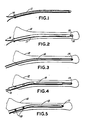
- FIG. 1 is a schematic view of a device according to the invention comprising a sleeve and a looped internal filamentary retaining element;
- FIG. 2 is a schematic view of the sleeve of Fig. 1 inserted in a bone with the loop of the filamentary element extending from the distal end of said sleeve;
- FIG. 3 is a schematic view showing a locking bolt inserted in the looped filamentary element;
- FIG. 4 is a schematic view of a device according to the invention showing a locking bolt inserted in the distal end of a bone, with a filamentary element tightly looped around it, and an intramedullary nail partially inserted into the bone around the filamentary element;
- FIG. 5 is a schematic view of an intramedullary nail fully inserted and secured by locking bolts at its distal and proximal ends;
- FIG. 6 is a perspective view of a section of a intramedullary nail with apparatus for locking the ends of the filamentary element;
- FIG. 7 is a top view of the assembled apparatus of FIG. 6, with the wire loose;
- FIG. 8 is a top view of the assembled apparatus of FIG. 6, with the wire tightened;
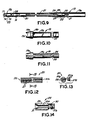
- FIG. 9 is a longitudinal cross-section of an intramedullary nail according to a preferred embodiment of the invention;
- FIG. 10 is a side view of
block 19 shown in Fig. 9; - FIG. 11 is a top view of
block 19; - FIG. 12 is a side view in cross-section of
cylinder 20 shown in Fig. 9; - FIG. 13 is a cross-section of
cylinder 20 taken at line 13-13 of Fig. 12; and - FIG. 14 is a side view in cross section of
nut 22 shown in Fig. 9. - Referring first to Figs. 1-5, a device according to the invention in its basic form is shown in Fig. 1. As shown there it comprises a
sleeve 11 and a loopedfilamentary element 14. The sleeve may be made out of various materials, for example physiologically acceptable metal or synthetic resin. If a synthetic resin is used it should be capable of heat sterilization. The filamentary element is preferably a metal wire or cable again made of a physiologically acceptable metal. In some instances an inert synthetic resin yarn or line may be used. Again the material should be capable of heat sterilization. - The sleeve is, of course, open at both ends and is flexible enough to follow the contours of the medulla as it is inserted.
- In use, as shown in Fig. 2,
sleeve 11 is inserted into the reamed-out medulla ofbone 12 down to the position to which the intramedullary nail is desired to extend. As shown in Fig. 1, theelement 14 is already inside theplastic sleeve 11; however it may be inserted after thesleeve 11 is in place. When thesleeve 11 is seated in the medulla, theelement 14 is pushed down so that it forms loop 16 beyond thedistal tip 15 of the sleeve. Within the constraints of the bore in the medulla,loop 16 may be made as large as desired, so that a transverse locking bolt or retaining pin may be inserted without fine aiming. As shown in Fig. 3, lockingbolt 17 is then inserted throughloop 16. After thelocking bolt 17 is inserted, theelement 14 is pulled tight and kept under tension. Theplastic sleeve 11 may then be removed and, as shown in Fig. 4, anintramedullary nail 13 inserted into thebone 12 aroundfilamentary element 14. Alternatively, the sleeve may be left in place and the nail inserted over or within it. The proximal end of the nail may be secured by lockingbolts 18 in the conventional way and the ends of the filamentary element are secured under tension to the proximal end of the nail, preferably in the manner described below. - A preferred device and method of securing the ends of the filamentary element to the nail is illustrated in Figs. 6, 7 and 8. As shown in Fig. 6 the proximal segment 4 of
nail 13 is in the shape of a truncated cone, with the proximal end wider. The inner surface of proximal segment 4 is threaded. Aconical retainer 2 is provided, having its outer surface threaded to engage internal threads of the proximal segment 4 of thenail 13. The inside ofretainer 2 has straight (i.e., not tapered) sides with opposinglongitudinal grooves 5. Both ends offilamentary element 14 run insideretainer 2, lying in thegrooves 5. A locking device 1 is provided to lock the filamentary element in theretainer 2. Locking device 1 has a stem 6 and atop 7 withcurved sides 7a.Indentations 8 which can accommodateelement 14 are formed in thecurved sides 7a. A hexagonallongitudinal hole 3 is provided through the center of the device. - In use,
retainer 2 is screwed into the socket at the proximal end 4 ofnail 13, the ends offilamentary element 14 being removed from thegrooves 5 as this occurs. When the retainer is fully seated, the end segments of the filament are placed ingrooves 5 and locking device 1 is slid down, the sleeve 6 sliding into the central hole of theretainer 2 with flangedupper surface 7 of locking device 1 seated on the rim of the retainer, but inside thenail 13. This arrangement is shown in Fig. 7, with the end segments of thefilamentary element 14 lodged in thegrooves 5 and seated in theindentations 8 of the top of the locking device 1. Using a hexagonal screwdriver the locking device is then turned clockwise. The top of the locking device then bears against the end segments of the filamentary element as shown in Fig. 8, forcing them into thegrooves 5 and firmly retaining them in their desired positions innail 13. - In the method disclosed in Figs. 1-5, a sleeve is used to position the filamentary element in the medulla before the nail is inserted. It is, however, possible to use a nail specifically designed to be used with a filamentary retaining element and to position the filamentary element in the medulla without the use of an auxiliary sleeve. Such a device is shown in Figs. 9-14.
- Referring to Fig. 9 an
intramedullary nail 13 has the usual elongated tubular casing 13a with anaperture 13b at its distal end. Inside the nail at its distal end is positioned ablock 19, shown in detail in Figs. 10 and 11. Theblock 19 has an enlarged head 19a and an extendedcylindrical body 19b. Thebody 19b is approximately the same diameter as the internal diameter ofnail 13, so that when inserted in the distal end of the nail the shoulders 19c of the head of the block abut the edge or rim of the end of the nail. - The head 19a of the block has a semi-circular cutout section 19d adapted to receive a transverse locking bolt. Grooves 24 for receiving a
filamentary retaining element 14 are provided along the sides ofblock 19. - Proximal to the
block 19 insidenail 13 is positioned aguide cylinder 20, shown in detail in Figs. 12 and 13.Cylinder 20 in one transverse dimension has the same diameter as the inner diameter of thenail 13. Its sides in the transverse direction have flats 20a. Twoholes 26 running parallel to the longitudinal axis of thecylinder 20 and extending about half way into the cylinder are provided for receiving the ends of the filamentary element. Transverse screw holes 27 for screws 27a are provided for retaining the ends of the filamentary element in theholes 26. - The
cylinder 20 is further provided at its proximal end with a tappedsocket 20b which receives the threaded end of arod 21.Rod 21, which has a diameter smaller than the interior diameter ofnail 13, extends toward the proximal end of the nail and is threaded into anut 22 shown in detail in Fig. 14.Nut 22 has acylindrical body 28 of a diameter approximating that of the interior ofnail 13 and anextension 30 which may be given a hexagonal configuration of lesser width. The distal end of the nut has aconical entry 31, and a central passage 31a which leads to a tappedsection 31b in the hexagonal extension into whichrod 21 is threaded. - In use, the nail is assembled by loading the
block 19,cylinder 20 androd 21 into the nail through, its distal end. Theblock 19 is retained in the nail by crimping the nail to engage thedimple 25 in the side of the block. Thenut 22 is then slipped over the proximal end ofrod 21 and engaged in the threadedextension 30, the hexagonal outer surface of the extension providing operating surfaces for a suitable socket wrench.Crimp 29 innail 13 preventsnut 22 from moving farther distally within the nail. - Thus assembled, the nail is inserted in the medulla of the bone to be treated in the normal way. By turning
hexagonal extension 30 in onedirection rod 21 is moved in a distal direction, movingcylinder 20 onrod 21 and also movingfilamentary element 14 distally to form a large loop at the distal end of the nail. A transverse locking bolt 17 (Fig. 9) may then be inserted through the loop ofelement 14. The loop is tightened about the bolt by turning thenut extension 30 in the opposite direction. This drawsrod 21 in the proximaldirection pulling cylinder 20 in the same direction and with it thefilamentary element 14.
Claims (14)
an elongated, tubular sleeve (11) adapted for insertion into the medulla of a long bone (12) and
a looped filamentary retaining element (14) inside said sleeve (11), said retaining element (14) being extendable to form a loop (16) outside one end of said sleeve (11).
a sleeve (11) adapted to be inserted into the medulla of a long bone (12);
a filamentary retaining element (14) adapted to be inserted into the sleeve (11) and to form a loop (16) at the distal end (15) thereof; and
an intramedullary nail (13) dimensioned to fit over the sleeve (11) or dimensioned to fit within the sleeve (11).
a hollow retaining cylinder (2) adapted to be inserted in one end (4) of the intramedullary nail (13) around the end segments of said filamentary retaining element (14); and
a locking device (1) for insertion into said retaining cylinder (2) thereby to press the end segments of the filamentary retaining element (14) against the interior of the retaining cylinder (2).
said retaining cylinder (2) has grooves (5) for receiving the end segments of said filamentary retaining element (14); and the locking device (1) comprises a rotatable sleeve (6) for insertion into the retaining cylinder (2) and a top (7) for pressing the end segments of said filamentary retaining element (14) into the grooves (5), when said sleeve (6) is rotated.
a block (19) at the distal end of the nail (13), said block (19) having means for receiving said filamentary retaining element (14);
a guide cylinder (20) with means for securing the ends of the filamentary retaining element (14);
a rod (21) having one end secured to said guide cylinder (20); and
a nut (22), secured to the nail (13) adjacent its proximal end, the other end of said rod (21) being threaded through said nut (22), whereby rotation of said nut (22) moves said guide cylinder (20) and said filamentary retaining element (14) axially of said rod (21) to extend or withdraw the loop (16) of said filamentary retaining element (14) from the distal end of the nail (13).
a cylindrical body (28);
an extension (30) of preferably hexagonal configuration of lesser diameter than said cylindrical body (28); and a conical entry (31) at its distal end, adapted to receive the rod (21).
Applications Claiming Priority (2)
| Application Number | Priority Date | Filing Date | Title |
|---|---|---|---|
| US439706 | 1989-11-21 | ||
| US07/439,706 US5034012A (en) | 1989-11-21 | 1989-11-21 | Intramedullary nail with loop tip |
Publications (2)
| Publication Number | Publication Date |
|---|---|
| EP0428985A1 true EP0428985A1 (en) | 1991-05-29 |
| EP0428985B1 EP0428985B1 (en) | 1995-03-15 |
Family
ID=23745811
Family Applications (1)
| Application Number | Title | Priority Date | Filing Date |
|---|---|---|---|
| EP90121754A Expired - Lifetime EP0428985B1 (en) | 1989-11-21 | 1990-11-14 | Intramedullary nail with loop tip |
Country Status (5)
| Country | Link |
|---|---|
| US (1) | US5034012A (en) |
| EP (1) | EP0428985B1 (en) |
| JP (1) | JPH0640885B2 (en) |
| CA (1) | CA2009802C (en) |
| DE (1) | DE69017844T2 (en) |
Cited By (6)
| Publication number | Priority date | Publication date | Assignee | Title |
|---|---|---|---|---|
| WO1997001990A1 (en) * | 1995-06-30 | 1997-01-23 | Dominique Persoons | Intramedullary pin |
| DE102005023069A1 (en) * | 2005-05-19 | 2006-11-23 | Pieske, Oliver, Dr.med. | Implant for connecting two parts of a substantially smooth breakage of a tubular bone comprises a shaped elongate member which has at least one axial channel with a constant diameter |
| WO2008061543A1 (en) | 2006-11-21 | 2008-05-29 | Oliver Pieske | Implant for tubular bones, and treatment method |
| ITTO20120687A1 (en) * | 2012-07-31 | 2014-02-01 | Im Ligure S R L Unipersonale | INTRAMIDOLLAR NAIL. |
| GB2527991A (en) * | 2013-03-15 | 2016-01-06 | Faro Tech Inc | Diagnosing multipath interference and eliminating multipath interference in 3D scanners by directed probing |
| WO2023118562A1 (en) * | 2021-12-23 | 2023-06-29 | Orthofix S.R.L. | Orthopedic cable bone transport device and bone transport system comprising said device |
Families Citing this family (42)
| Publication number | Priority date | Publication date | Assignee | Title |
|---|---|---|---|---|
| US5281225A (en) * | 1989-06-07 | 1994-01-25 | Guglielmo Vicenzi | Intramedullary pin with self-locking end for metadiaphyseal fractures of long bones |
| US5190549A (en) * | 1990-08-02 | 1993-03-02 | Exactech, Inc. | Locking surgical tool handle system |
| US5179915A (en) * | 1992-01-06 | 1993-01-19 | Osteonics Corporation | Anatomically matching intramedullary alignment rod |
| US5266075A (en) * | 1992-10-05 | 1993-11-30 | Roy Clark | Tendon threader for endosteal ligament mounting |
| US5429638A (en) * | 1993-02-12 | 1995-07-04 | The Cleveland Clinic Foundation | Bone transport and lengthening system |
| US5626579A (en) * | 1993-02-12 | 1997-05-06 | The Cleveland Clinic Foundation | Bone transport and lengthening system |
| US5536269A (en) * | 1993-02-18 | 1996-07-16 | Genesis Orthopedics | Bone and tissue lengthening device |
| US5350379A (en) * | 1993-02-18 | 1994-09-27 | Genesis Orthopedics | Bone and tissue lengthening device |
| EP0706782B1 (en) * | 1994-10-14 | 1999-06-30 | Synthes AG, Chur | Osteosynthetic longitudinal alignment and/or fixation device |
| US5643273A (en) * | 1995-02-17 | 1997-07-01 | Clark; Ron | ACL bone tunnel projection drill guide and method for its use |
| US5707394A (en) * | 1996-02-07 | 1998-01-13 | Bristol-Myers Squibb Company | Pre-loaded suture anchor with rigid extension |
| US5697950A (en) * | 1996-02-07 | 1997-12-16 | Linvatec Corporation | Pre-loaded suture anchor |
| ATE224675T1 (en) * | 1996-12-02 | 2002-10-15 | Synthes Ag | FLAT INTEGRAL NAIL |
| ATE294538T1 (en) | 1999-11-11 | 2005-05-15 | Synthes Ag | RADIALLY EXPANDABLE INTEGRAL NAIL |
| US6551321B1 (en) | 2000-06-23 | 2003-04-22 | Centerpulse Orthopedics Inc. | Flexible intramedullary nail |
| KR100393256B1 (en) * | 2000-06-27 | 2003-07-31 | 박일형 | Intramedullary nail and interlocking method of distal screw through the nail |
| EP1358852B1 (en) * | 2002-05-03 | 2005-12-14 | Luciano Trinchese | Apparatus for the osteosynthesis of bone fractures by means of locked endomedullary nailing |
| US7101376B2 (en) * | 2003-04-04 | 2006-09-05 | Elliot Charles Semet | Interlocking IM Nails with threaded guidewire |
| CN1819803A (en) * | 2003-04-10 | 2006-08-16 | 库尔斯恩蒂斯股份公司 | Device for splinting toes temporarily |
| ATE418923T1 (en) * | 2003-07-30 | 2009-01-15 | Synthes Gmbh | SURGICAL NAIL |
| CN100364484C (en) * | 2005-02-28 | 2008-01-30 | 刘志成 | Intramedullary nail with drawing wire |
| US8287541B2 (en) | 2005-05-18 | 2012-10-16 | Sonoma Orthopedic Products, Inc. | Fracture fixation device, tools and methods |
| US8961516B2 (en) | 2005-05-18 | 2015-02-24 | Sonoma Orthopedic Products, Inc. | Straight intramedullary fracture fixation devices and methods |
| US7909825B2 (en) | 2006-11-22 | 2011-03-22 | Sonoma Orthepedic Products, Inc. | Fracture fixation device, tools and methods |
| AU2006247498A1 (en) | 2005-05-18 | 2006-11-23 | Sonoma Orthopedic Products, Inc. | Minimally invasive actuable bone fixation devices, systems and methods of use |
| US9060820B2 (en) | 2005-05-18 | 2015-06-23 | Sonoma Orthopedic Products, Inc. | Segmented intramedullary fracture fixation devices and methods |
| US20070173835A1 (en) * | 2006-01-13 | 2007-07-26 | Medoff Robert J | Intramedullary implant for fracture fixation and method of using the same |
| US7931651B2 (en) | 2006-11-17 | 2011-04-26 | Wake Lake University Health Sciences | External fixation assembly and method of use |
| US8377016B2 (en) | 2007-01-10 | 2013-02-19 | Wake Forest University Health Sciences | Apparatus and method for wound treatment employing periodic sub-atmospheric pressure |
| US20080208171A1 (en) * | 2007-02-23 | 2008-08-28 | Argenta Louis C | Device and method for removing edema |
| WO2010006195A1 (en) * | 2008-07-09 | 2010-01-14 | Amei Technologies, Inc. | Ankle arthrodesis nail and outrigger assembly |
| US8414584B2 (en) * | 2008-07-09 | 2013-04-09 | Icon Orthopaedic Concepts, Llc | Ankle arthrodesis nail and outrigger assembly |
| EP2341857A2 (en) | 2008-09-26 | 2011-07-13 | Sonoma Orthopedic Products, Inc. | Bone fixation device, tools and methods |
| US9510878B2 (en) | 2009-11-16 | 2016-12-06 | The Research Foundation For The State University Of New York | Pre-curved intramedullary clavicle nail and method of using same |
| US20120310283A1 (en) * | 2011-06-02 | 2012-12-06 | Morreale Vittorio M | Segmental spinal fixation system and a method of fixating a plurality of spinal segments |
| KR102119375B1 (en) * | 2012-02-16 | 2020-06-09 | 신세스 게엠바하 | Drug eluting insert for implantable body |
| JP6373282B2 (en) * | 2013-02-08 | 2018-08-15 | ゴースリン,ロバート | Systems, methods and devices for bone healing, stabilization or fixation |
| WO2015017074A1 (en) * | 2013-07-02 | 2015-02-05 | Cmarr Enterprises | Curved tibiotalar fusion nail and method of use |
| US9770278B2 (en) | 2014-01-17 | 2017-09-26 | Arthrex, Inc. | Dual tip guide wire |
| US9814499B2 (en) | 2014-09-30 | 2017-11-14 | Arthrex, Inc. | Intramedullary fracture fixation devices and methods |
| JP6964599B2 (en) * | 2016-04-15 | 2021-11-10 | アースレックス インコーポレイテッド | Joint fixation device |
| US10912652B2 (en) | 2018-07-09 | 2021-02-09 | Arthrex, Inc. | Arthroplasty implant systems for generating and applying dynamic compression |
Citations (3)
| Publication number | Priority date | Publication date | Assignee | Title |
|---|---|---|---|---|
| CH275268A (en) * | 1949-07-13 | 1951-05-15 | Sannmann Alfred | Apparatus for braiding the ends of a wire tied around an object. |
| DE3347333A1 (en) * | 1982-12-24 | 1984-06-28 | Mecron Medizinische Produkte Gmbh, 1000 Berlin | Compression nail arrangement |
| US4557259A (en) * | 1983-08-10 | 1985-12-10 | Henry Ford Hospital | Surgical method and apparatus for inserting wire into the spine |
Family Cites Families (10)
| Publication number | Priority date | Publication date | Assignee | Title |
|---|---|---|---|---|
| DE532698C (en) * | 1929-07-13 | 1931-09-02 | Moritz Borchardt Dr | Device for tightening the wires used to strengthen bone fractures |
| US2049361A (en) * | 1934-10-27 | 1936-07-28 | Ericsson Ernst Axel Johan | Wire or ribbon tightening apparatus |
| DE1248228B (en) * | 1965-03-24 | 1967-08-24 | Hans Juergen Kaessmann Dr | Device for the treatment of broken tubular bones by means of pressure osteosynthesis |
| US4409974A (en) * | 1981-06-29 | 1983-10-18 | Freedland Jeffrey A | Bone-fixating surgical implant device |
| EP0070252A1 (en) * | 1981-07-08 | 1983-01-19 | Ciba-Geigy Ag | Machine for checking the completion of the filling of press-through packs |
| US4574795A (en) * | 1982-12-24 | 1986-03-11 | Mecron Medizinische Produkte Gmbh | Compression nail assembly |
| SU1111748A1 (en) * | 1983-04-08 | 1984-09-07 | Киевский медицинский институт | Apparatus for osteosynthesis of tubular bones |
| US4561432A (en) * | 1983-09-15 | 1985-12-31 | Floyd A. Coard, M.D. | Fractured femur fixation system |
| CH668173A5 (en) * | 1984-05-14 | 1988-12-15 | Synthes Ag | DEVICE FOR FIXING TUBE BONE FRACTURES WITH A BONE MARBLE NAIL AND AT LEAST ONE CROSS-BOLT LOCKING. |
| GB8721661D0 (en) * | 1987-09-15 | 1987-10-21 | Showell A W Sugicraft Ltd | Spinal/skull fixation device |
-
1989
- 1989-11-21 US US07/439,706 patent/US5034012A/en not_active Expired - Lifetime
-
1990
- 1990-02-12 CA CA002009802A patent/CA2009802C/en not_active Expired - Lifetime
- 1990-11-14 EP EP90121754A patent/EP0428985B1/en not_active Expired - Lifetime
- 1990-11-14 DE DE69017844T patent/DE69017844T2/en not_active Expired - Fee Related
- 1990-11-20 JP JP2313013A patent/JPH0640885B2/en not_active Expired - Lifetime
Patent Citations (3)
| Publication number | Priority date | Publication date | Assignee | Title |
|---|---|---|---|---|
| CH275268A (en) * | 1949-07-13 | 1951-05-15 | Sannmann Alfred | Apparatus for braiding the ends of a wire tied around an object. |
| DE3347333A1 (en) * | 1982-12-24 | 1984-06-28 | Mecron Medizinische Produkte Gmbh, 1000 Berlin | Compression nail arrangement |
| US4557259A (en) * | 1983-08-10 | 1985-12-10 | Henry Ford Hospital | Surgical method and apparatus for inserting wire into the spine |
Cited By (10)
| Publication number | Priority date | Publication date | Assignee | Title |
|---|---|---|---|---|
| WO1997001990A1 (en) * | 1995-06-30 | 1997-01-23 | Dominique Persoons | Intramedullary pin |
| DE102005023069A1 (en) * | 2005-05-19 | 2006-11-23 | Pieske, Oliver, Dr.med. | Implant for connecting two parts of a substantially smooth breakage of a tubular bone comprises a shaped elongate member which has at least one axial channel with a constant diameter |
| DE102005023069B4 (en) * | 2005-05-19 | 2009-07-09 | Pieske, Oliver, Dr.med. | Implant for tensile strength joining two parts of a substantially smoothly broken tubular bone |
| WO2008061543A1 (en) | 2006-11-21 | 2008-05-29 | Oliver Pieske | Implant for tubular bones, and treatment method |
| US8133225B2 (en) | 2006-11-21 | 2012-03-13 | Oliver Pieske | Implant for long bones and treatment method |
| ITTO20120687A1 (en) * | 2012-07-31 | 2014-02-01 | Im Ligure S R L Unipersonale | INTRAMIDOLLAR NAIL. |
| WO2014020488A1 (en) * | 2012-07-31 | 2014-02-06 | Im Ligure S.R.L. Unipersonale | Intramedullary pin |
| GB2527991A (en) * | 2013-03-15 | 2016-01-06 | Faro Tech Inc | Diagnosing multipath interference and eliminating multipath interference in 3D scanners by directed probing |
| GB2527991B (en) * | 2013-03-15 | 2018-08-15 | Faro Tech Inc | Diagnosing multipath interference and eliminating multipath interference in 3D scanners by directed probing |
| WO2023118562A1 (en) * | 2021-12-23 | 2023-06-29 | Orthofix S.R.L. | Orthopedic cable bone transport device and bone transport system comprising said device |
Also Published As
| Publication number | Publication date |
|---|---|
| US5034012A (en) | 1991-07-23 |
| JPH0640885B2 (en) | 1994-06-01 |
| DE69017844T2 (en) | 1995-07-27 |
| CA2009802A1 (en) | 1991-05-21 |
| EP0428985B1 (en) | 1995-03-15 |
| DE69017844D1 (en) | 1995-04-20 |
| CA2009802C (en) | 1995-08-15 |
| JPH03173555A (en) | 1991-07-26 |
Similar Documents
| Publication | Publication Date | Title |
|---|---|---|
| US5034012A (en) | Intramedullary nail with loop tip | |
| KR0176264B1 (en) | Locking cap for medical implants | |
| US6149654A (en) | Intra-articular drill | |
| US4940467A (en) | Variable length fixation device | |
| US4456005A (en) | External compression bone fixation device | |
| US6406477B1 (en) | Intramedullary nail | |
| US6648889B2 (en) | Intramedullary hip nail with bifurcated lock | |
| US6524314B1 (en) | Interlocking intramedullary nail | |
| US6443954B1 (en) | Femoral nail intramedullary system | |
| JP2599777B2 (en) | Proximal femur fracture fixation device | |
| US6569165B2 (en) | Modular intramedullary nail | |
| US7785326B2 (en) | System for intramedullary rod fixation and method therefor | |
| US4790304A (en) | Self-locking pin device particularly useful for internally fixing bone fractures | |
| US8100911B2 (en) | Fracture fixation apparatus | |
| US4640271A (en) | Bone screw | |
| US7175631B2 (en) | Radiolucent aiming guide | |
| US4235428A (en) | Bone transfixation pin guide | |
| US20110137356A1 (en) | Bone compression device and methods | |
| US20080119854A1 (en) | Bone fixture apparatus and jig | |
| US20100145396A1 (en) | Bolt Apparatus | |
| US7488328B2 (en) | Targeting apparatus for bone fixation device | |
| US5439465A (en) | Bone compression and distraction surgical tool | |
| WO1989006940A1 (en) | Variable length fixation device | |
| US7060070B1 (en) | Locking nail and aim-taking apparatus | |
| AU5198500A (en) | Inramedullary nail, in particular, intramedullary nail for the tibia |
Legal Events
| Date | Code | Title | Description |
|---|---|---|---|
| PUAI | Public reference made under article 153(3) epc to a published international application that has entered the european phase |
Free format text: ORIGINAL CODE: 0009012 |
|
| 17P | Request for examination filed |
Effective date: 19901114 |
|
| AK | Designated contracting states |
Kind code of ref document: A1 Designated state(s): CH DE FR GB LI |
|
| 17Q | First examination report despatched |
Effective date: 19930715 |
|
| GRAA | (expected) grant |
Free format text: ORIGINAL CODE: 0009210 |
|
| AK | Designated contracting states |
Kind code of ref document: B1 Designated state(s): CH DE FR GB LI |
|
| ET | Fr: translation filed | ||
| REF | Corresponds to: |
Ref document number: 69017844 Country of ref document: DE Date of ref document: 19950420 |
|
| PLBE | No opposition filed within time limit |
Free format text: ORIGINAL CODE: 0009261 |
|
| STAA | Information on the status of an ep patent application or granted ep patent |
Free format text: STATUS: NO OPPOSITION FILED WITHIN TIME LIMIT |
|
| 26N | No opposition filed | ||
| REG | Reference to a national code |
Ref country code: GB Ref legal event code: IF02 |
|
| REG | Reference to a national code |
Ref country code: CH Ref legal event code: PUE Owner name: SYNTHES GMBH Free format text: SYNTHES AG CHUR#GRABENSTRASSE 15#7000 CHUR (CH) -TRANSFER TO- SYNTHES GMBH#EIMATTSTRASSE 3#4436 OBERDORF (CH) |
|
| REG | Reference to a national code |
Ref country code: GB Ref legal event code: 732E |
|
| REG | Reference to a national code |
Ref country code: FR Ref legal event code: TP |
|
| PGFP | Annual fee paid to national office [announced via postgrant information from national office to epo] |
Ref country code: CH Payment date: 20081117 Year of fee payment: 19 Ref country code: DE Payment date: 20081107 Year of fee payment: 19 |
|
| PGFP | Annual fee paid to national office [announced via postgrant information from national office to epo] |
Ref country code: FR Payment date: 20081112 Year of fee payment: 19 |
|
| PGFP | Annual fee paid to national office [announced via postgrant information from national office to epo] |
Ref country code: GB Payment date: 20081112 Year of fee payment: 19 |
|
| REG | Reference to a national code |
Ref country code: CH Ref legal event code: PL |
|
| GBPC | Gb: european patent ceased through non-payment of renewal fee |
Effective date: 20091114 |
|
| REG | Reference to a national code |
Ref country code: FR Ref legal event code: ST Effective date: 20100730 |
|
| PG25 | Lapsed in a contracting state [announced via postgrant information from national office to epo] |
Ref country code: CH Free format text: LAPSE BECAUSE OF NON-PAYMENT OF DUE FEES Effective date: 20091130 Ref country code: LI Free format text: LAPSE BECAUSE OF NON-PAYMENT OF DUE FEES Effective date: 20091130 Ref country code: FR Free format text: LAPSE BECAUSE OF NON-PAYMENT OF DUE FEES Effective date: 20091130 |
|
| PG25 | Lapsed in a contracting state [announced via postgrant information from national office to epo] |
Ref country code: DE Free format text: LAPSE BECAUSE OF NON-PAYMENT OF DUE FEES Effective date: 20100601 |
|
| PG25 | Lapsed in a contracting state [announced via postgrant information from national office to epo] |
Ref country code: GB Free format text: LAPSE BECAUSE OF NON-PAYMENT OF DUE FEES Effective date: 20091114 |