EP0430043A2 - Digital signal processing circuit - Google Patents
Digital signal processing circuit Download PDFInfo
- Publication number
- EP0430043A2 EP0430043A2 EP90122212A EP90122212A EP0430043A2 EP 0430043 A2 EP0430043 A2 EP 0430043A2 EP 90122212 A EP90122212 A EP 90122212A EP 90122212 A EP90122212 A EP 90122212A EP 0430043 A2 EP0430043 A2 EP 0430043A2
- Authority
- EP
- European Patent Office
- Prior art keywords
- circuit
- signal
- recording
- playback
- output
- Prior art date
- Legal status (The legal status is an assumption and is not a legal conclusion. Google has not performed a legal analysis and makes no representation as to the accuracy of the status listed.)
- Granted
Links
Images


Classifications
-
- G—PHYSICS
- G11—INFORMATION STORAGE
- G11B—INFORMATION STORAGE BASED ON RELATIVE MOVEMENT BETWEEN RECORD CARRIER AND TRANSDUCER
- G11B15/00—Driving, starting or stopping record carriers of filamentary or web form; Driving both such record carriers and heads; Guiding such record carriers or containers therefor; Control thereof; Control of operating function
- G11B15/18—Driving; Starting; Stopping; Arrangements for control or regulation thereof
- G11B15/1808—Driving of both record carrier and head
- G11B15/1875—Driving of both record carrier and head adaptations for special effects or editing
-
- G—PHYSICS
- G11—INFORMATION STORAGE
- G11B—INFORMATION STORAGE BASED ON RELATIVE MOVEMENT BETWEEN RECORD CARRIER AND TRANSDUCER
- G11B20/00—Signal processing not specific to the method of recording or reproducing; Circuits therefor
- G11B20/10—Digital recording or reproducing
-
- G—PHYSICS
- G11—INFORMATION STORAGE
- G11B—INFORMATION STORAGE BASED ON RELATIVE MOVEMENT BETWEEN RECORD CARRIER AND TRANSDUCER
- G11B27/00—Editing; Indexing; Addressing; Timing or synchronising; Monitoring; Measuring tape travel
- G11B27/02—Editing, e.g. varying the order of information signals recorded on, or reproduced from, record carriers
- G11B27/031—Electronic editing of digitised analogue information signals, e.g. audio or video signals
- G11B27/036—Insert-editing
-
- G—PHYSICS
- G11—INFORMATION STORAGE
- G11B—INFORMATION STORAGE BASED ON RELATIVE MOVEMENT BETWEEN RECORD CARRIER AND TRANSDUCER
- G11B27/00—Editing; Indexing; Addressing; Timing or synchronising; Monitoring; Measuring tape travel
- G11B27/10—Indexing; Addressing; Timing or synchronising; Measuring tape travel
- G11B27/102—Programmed access in sequence to addressed parts of tracks of operating record carriers
- G11B27/107—Programmed access in sequence to addressed parts of tracks of operating record carriers of operating tapes
-
- G—PHYSICS
- G11—INFORMATION STORAGE
- G11B—INFORMATION STORAGE BASED ON RELATIVE MOVEMENT BETWEEN RECORD CARRIER AND TRANSDUCER
- G11B27/00—Editing; Indexing; Addressing; Timing or synchronising; Monitoring; Measuring tape travel
- G11B27/10—Indexing; Addressing; Timing or synchronising; Measuring tape travel
- G11B27/19—Indexing; Addressing; Timing or synchronising; Measuring tape travel by using information detectable on the record carrier
- G11B27/28—Indexing; Addressing; Timing or synchronising; Measuring tape travel by using information detectable on the record carrier by using information signals recorded by the same method as the main recording
- G11B27/30—Indexing; Addressing; Timing or synchronising; Measuring tape travel by using information detectable on the record carrier by using information signals recorded by the same method as the main recording on the same track as the main recording
- G11B27/3027—Indexing; Addressing; Timing or synchronising; Measuring tape travel by using information detectable on the record carrier by using information signals recorded by the same method as the main recording on the same track as the main recording used signal is digitally coded
- G11B27/3063—Subcodes
-
- G—PHYSICS
- G11—INFORMATION STORAGE
- G11B—INFORMATION STORAGE BASED ON RELATIVE MOVEMENT BETWEEN RECORD CARRIER AND TRANSDUCER
- G11B2220/00—Record carriers by type
- G11B2220/90—Tape-like record carriers
-
- G—PHYSICS
- G11—INFORMATION STORAGE
- G11B—INFORMATION STORAGE BASED ON RELATIVE MOVEMENT BETWEEN RECORD CARRIER AND TRANSDUCER
- G11B2220/00—Record carriers by type
- G11B2220/90—Tape-like record carriers
- G11B2220/91—Helical scan format, wherein tracks are slightly tilted with respect to tape direction, e.g. VHS, DAT, DVC, AIT or exabyte
- G11B2220/913—Digital audio tape [DAT] format
-
- G—PHYSICS
- G11—INFORMATION STORAGE
- G11B—INFORMATION STORAGE BASED ON RELATIVE MOVEMENT BETWEEN RECORD CARRIER AND TRANSDUCER
- G11B27/00—Editing; Indexing; Addressing; Timing or synchronising; Monitoring; Measuring tape travel
- G11B27/02—Editing, e.g. varying the order of information signals recorded on, or reproduced from, record carriers
- G11B27/031—Electronic editing of digitised analogue information signals, e.g. audio or video signals
- G11B27/032—Electronic editing of digitised analogue information signals, e.g. audio or video signals on tapes
Definitions
- the present invention generally relates to digital signal processing circuits. More particularly, the invention relates to a digital signal processing circuit employed in a magnetic recording and playback apparatus for recording and playing back digital audio signals.
- a digital audio tape recorder comprises one type of magnetic recording and playback apparatus having a rotary drum arrangement to record and playback digital audio signals.
- the digital audio tape recorder is capable of converting an audio signal comprising analog elements into a digital signal for recording and playback. This feature makes it possible to effectively avoid degradation in sound quality while the audio signal is being recorded and playback with high degrees of density.
- One way to improve the ease of use and recording quality of the digital audio tape recorder is to switch its recording and playback speeds. This switching, as with conventional analog signal tape recorders, allows magnetic tapes to run at multiples of the standard speed so that the tapes may be run, for example two times, three times, or four times as fast as the standard speed.
- the digital audio tape recorder can also function as an external memory device for use with a computing apparatus.
- the recorder records and plays back serial digital data in place of digital audio signals at a speed compatible with the data transmission rate of the computer apparatus.
- the present invention provides a digital signal processing circuit allowing digital signals to be recorded and played back at various recording and reproducing speeds while effectively preventing the occurrence of data loses.
- the invention provides a digital tape recorder with a digital signal processing circuit and a magnetic tape wound around a rotary drum, the tape running at a constant speed relative to a rotating speed of the drum, the drum rotating speed and the tape running speed being changed in accordance with predetermined control data D CONT so that a digital signal entering a digital signal input/output circuit is converted by a recording signal processing circuit to a recording signal for recording onto the magnetic tape and/or a playback signal S RF from the magnetic tape is converted by a playback signal demodulation circuit to the digital signal for output via the digital signal input/output circuit; operating frequencies of the digital signal input/output circuit, the recording signal processing circuit, and the playback signal demodulation circuit being switched in accordance with the control data D CONT .
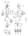
- FIGs. 1 and 2 there is illustrated in block diagram form a circuit for a digital audio tape (DAT) recorder 1 embodying principles of the invention.
- DAT digital audio tape
- Fig. 2 illustrates the overall arrangement of the DAT recorder 1.
- Fig. 1 illustrates a digital signal processing circuit 8 that can be used in the arrangement of Fig. 2.
- a DAT recorder can be used to convert analog stereo audio signals into digital signals for recording purposes.
- the DAT recorder 1 has an input display circuit 2 that outputs operation data P SOU in response to an operator's actions and also switches on or off suitable displays on a display panel (not shown) in accordance with appropriate control data.
- the operator's input can be made via a keyboard and the display panel can comprise liquid crystal display (LCD) elements.
- LCD liquid crystal display
- the DAT recorder has three basic modes: recording, after recording, and playback. Further, the DAT recorder has a long play (LP) mode and a standard play (SP) mode discussed further below.
- LP long play
- SP standard play
- a system control circuit 6 In recording, a system control circuit 6 generates control data P CONT , in accordance with the operation data P SOU and further configuration data, which configuration data is established in advance to reflect the configuration of the DAT recorder 1, such as the selected rotary drum arrangement.
- the control data D CONT is referenced when recording digital audio signals in response to the operators actions.
- control data D CONT is generated by the system control circuit 6 in accordance with status byte data supplied by the digital signal processing circuit 8, the operation data D SOU , and the configuration data.
- control data D CONT is thus used for two purposes: to switch the operation mode of the DAT recorder 1 in response to the operators actions and to effect playback of digital audio signals from a magnetic tape 10 in accordance with the recording format recorded thereon.
- the control data P CONT preferably comprises serial data in the form of a byte, which byte is used both as a mode byte and as a status byte, each byte comprising eight (8) bits.
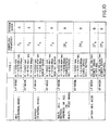
- a table is provided to illustrate the correlations between the various bits of the mode byte and the various modes of the DAT recorder 1.
- the two highest-order bits in the mode byte identify the diameter of the rotary drum 16 as well as magnetic head rotation.
- a two bit value is set in a servo circuit 12 in accordance with the configuration of the rotary drum 16 and other configuration settings, the two bit value being output as the two highest-order bits from the system control circuit 6.
- the two-bit values "00”, “01”, “10”, and “11” indicate whether the configuration of the rotary drum 16 and the magnetic heads of the DAT recorder 1 is of type "A", “B”, “C”, or “D”, respectively. These various configuration types are discussed below.
- the third highest-order bit of the mode byte preferably identifies whether the DAT recorder 1 is in its test signal recording mode. When the third highest order bit is set to "1", it preferably means that the DAT recorder 1 is in its test signal recording mode.
- the fourth highest order bit of the mode byte preferably identifies whether the DAT recorder 1 is in a recording mode. When the fourth highest order bit is set to a "1", it preferably means that the DAT recorder 1 is in its recording mode.
- the fifth highest order bit of the mode byte preferably indicates whether the DAT recorder 1 is in an after-recording mode.
- the fifth highest order bit is set to a "1" it preferably means that the DAT recorder 1 is in its after recording mode.
- the sixth highest order bit of the mode byte preferably indicates whether the DAT recorder 1 is in normal speed mode or, multiple speed mode, the normal speed mode being a mode in which recording or playback is undertaken at a normal tape speed, and the multiple speed mode being a mode in which recording or playback is undertaken at tape speeds that are multiples of the normal tape speed.
- a setting of the sixth highest order bit to a "0" preferably means that the DAT recorder 1 will rewind or playback in a normal speed mode while a setting of the sixth highest order bit to a "1" preferably means that the DAT recorder 1 will rewind or playback in a multiple speed mode.
- a mode byte of "--001000” preferably means that the DAT recorder 1 is in its after recording mode and the tape speed is set to a normal mode.
- a mode byte of "--001100” preferably means that the DAT recorder 1 is in it after recording mode and the tape speed is set to the multiple speed mode.
- a mode byte of "--01-0--" or “--01-1-1--” preferably means that the DAT recorder 1 is in its recording mode and the tape speed is set to either the normal mode or multiple speed mode respectively.
- a mode byte of "--01--0-" preferably indicates that the DAT recorder 1 has started recording while a mode byte of "--01--1-” preferably indicates that the DAT recorder 1 is ready for recording.
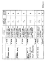
- the status byte is generated during recording by the system control circuit 6 in accordance with the control data D SOU .
- the status byte is generated by the digital signal processing circuit 8 in accordance with sub-code data recorded on the magnetic tape 10.
- the two highest-order bits of the status byte also referred to as D FS , represent a sampling frequency f S of the digital audio signal.
- the next two highest-order bits indicate the number of channels over which audio signals are recorded or played back by the digital audio tape recorder 1.
- the fifth and the sixth highest-order bits identify the type of quantization in effect when an audio signal is converted to a digital audio signal and vice-versa.
- the seventh and the eighth highest-order bits identify a track pitch value T P .
- a status byte of "100-01--” preferably means that a two-channel audio signal subjected to a 12-bit nonlinear quantization at a sampling frequency of 32 KHz is recorded in long play (LP) mode on the magnetic tape, or is played back therefrom in LP mode.
- a status byte of "01----01” preferably means that a magnetic tape recorded at 1.5 times the normal track pitch is reproduced in 1.5-fold track pitch mode.
- a status byte other than "100-01--" or "01----01” means that the magnetic tape is recorded in standard play (SP) mode, or the magnetic tape recorded in SP mode is played back.
- the DAT recorder 1 also includes a mechanical control circuit 11 that controls a tape cassette loading/ejecting mechanism, a magnetic tape loading mechanism, and other parts.
- the control is formulated in accordance with the control data D CONT provided by the system control circuit 6.
- a servo circuit 12 is provided that drives a reel motor 14 according to the control data D CONT , thereby rotating the reels of a magnetic tape cassette, not shown, at a predetermined speed.
- the servo circuit 12 also generates a switching pulse signal SWP whereby the signal level is switched on each revolution of the rotary drum 16 and, as per the control data D CONT , drives a drum motor 17 so that the switching pulse signal SWP reaches a predetermined phase relative to a rotating drum reference signal DREF.
- a rotary drum reference signal DREF preferably comprises a reference signal having a duty factor of 50%, the signal being repeated at interleaving intervals of 60 msec in LP mode and 30 msec in SP mode during normal recording or reproduction.
- the rotary drum 16 is controlled to rotate by an appropriate amount in each interleaving period.
- the servo circuit 12 drives a capstan motor 19 with reference to a tracking error signal provided by tracking control circuit 18, thereby providing tracking control while letting the magnetic tape run at a speed dictated by the control data D CONT .
- the servo circuit 12 switches the running speed of the magnetic tape 10 and the rotating speed of the rotary drum 16 in accordance with the control data D CONT , digitally records an audio signal on the tape 10 in the format specified by the operator's action, and plays back the digital audio signal from the tape 10 in view of the recording format recorded thereon.
- a first embodiment is constructed to be of the type A configuration. That is, a pair of magnetic heads 20A and 20B having different azimuth angles are located 180 degrees apart relative to each other on the rotary drum 16.
- the drum 16 preferably has a diameter of 30 mm.
- the magnetic tape 10 is then wound around a portion of the rotary drum 16 and held there against by rollers 16A and 16B so as to form a 90-degree angle between the tape leads 10A and 10B leading to and exiting from the drum 16, as illustrated.
- the servo circuit 12 switches the DAT recorder 1 between the various operation modes according to the control data D CONT .
- the servo control circuit 12 drives the drum motor 17 and capstan motor 19 so that the rotating speed N of the rotary drum 16 reaches 1000 rpm and the running speed V t of the magnetic tape 10 attains a speed of 4.075 mm/sec.
- the servo circuit 12 drives the drum motor 17 and capstan motor 19 so that the rotating speed N of the rotary drum 16 reaches 2000 rpm and the running speed V t of the magnetic tape 16 reaches 8.150 mm/sec. In this manner, scanning loci are formed successively on the magnetic heads 20A and 20B in accordance with the format specified, for the currently configured digital audio tape recorder.
- the drum motor 17 is driven so that the rotating speed N of the rotary drum 16 reaches 2000 rpm, while the capstan motor 19 is driven so that the running speed reaches 4.075 mm/sec in LP mode and 8.150 mm/sec in SP mode.
- the rotary drum 16 rotates at the same timing as for SP mode recording in normal mode.
- the tape 10 is controlled to run by one recording track per cycle of scanning by the magnetic heads 20A and 20B.
- the servo circuit 12 provides tracking control using the so-called automatic track finding (ATF) method as per the tracking error signal from the tracking control circuit 18.
- ATF automatic track finding
- the digital signal processing circuit 8 repeatedly acquires the playback signal S RF during LP mode playback. Selective processing of the playback signal S RF allows digital audio signals to be played back as desired.
- the servo circuit 12 provides tracking control (so-called semi-NT servo) as per the tracking error signal from the tracking control circuit 18 so that the magnetic heads 20A and 20B scan each required recording track twice on the magnetic tape 10.
- the servo circuit 12 drives the drum motor 17 and capstan motor 19 so that the rotating speed N of the rotary drum 16 reaches 2000 rpm and the running speed V t of the magnetic tape 10 reaches 8.150 mm/sec.
- the servo circuit 12 provides control so that the rotary drum 16 and the magnetic tape 10 in multiple speed mode operate two times as fast as in normal recording mode.
- the recording signal is supplied to the magnetic heads 20A and 20B in half of the normal recording cycle and at two times the normal transmission speed. This permits recording of the digital audio signal in the same format as for normal recording; in playback mode, the playback signal S RF is acquired with its signal level varying in half of the normal cycle of playback.
- the servo circuit 12 controls the drum motor 17 and capstan motor 19 so that the magnetic tape 10 runs and the rotary drum 16 rotates at the same speeds as in two times speed recording/playback mode. That is, in after-recording SP mode, the servo circuit 12 drives the rotary drum 16 and capstan motor 19 at the same timing as in normal mode; in LP mode, the servo circuit 12 drives these parts at the same timing as in two times speed recording/playback mode for ATF servo tracking control.
- an audio signal conversion circuit 21 that comprises an analog-to-digital conversion circuit, a digital-to-analog conversion circuit and a digital filter circuit, the circuits operating in reference to a clock signal S FS from the digital signal processing circuit 8.
- a stereo audio signal S IN entering the digital audio tape recorder 1 is converted to the digital audio signal D AU for output to the digital signal processing circuit 8.
- the digital audio signal D AU from the digital signal processing circuit 8 is converted by the audio signal conversion circuit 21 into an analog signal S OUT for output.
- the digital signal processing circuit 8 converts the digital audio signal D AU to the recording signal S REC as per the control data D CONT .
- the recording signal S REC is output via a recording and playback amplifier circuit 24 to the magnetic heads 20A and 20B.
- the digital audio signal D AU is recorded in this way on the magnetic tape 10 in the format specific to the currently configured digital audio tape recorder.
- Switching from recording mode to playback mode is achieved in accordance with the control data D CONT and as per the sub-code data obtained by demodulating a playback signal S RF retrieved from the tape.
- the playback signal S RF is converted to the digital audio signal D AU for output to the audio signal conversion circuit 21.
- the playback signal S RF from the magnetic heads 20A and 20B is demodulated so as to produce the digital audio signal D AU .
- a control data I/O circuit 20 places the control data D CONT , from the system control circuit 6 into a predetermined area of a memory circuit 44 via a bus arrangement and a memory interface circuit 42.
- control data I/O circuit 20 reads the status byte data from the sub-code data that was demodulated and placed in the memory circuit 44. The circuit 20 then sends the status byte data to the system control circuit 6. This causes the recording data recorded on the magnetic tape 10 to be retrieved therefrom and transmitted to the system control circuit 6.
- the memory circuit 44 in recording mode, accommodates as the control data D CONT the status byte and mode byte generated by the system control circuit 6.
- the memory circuit 44 admits as the control data D CONT both the mode byte data generated by the system control circuit 6 and the status byte data made up of the recording data recorded on the magnetic tape 10.
- the digital signal processing circuit 8 in recording mode, outputs the recording signal S REC in response to the operator's action and in accordance with the configuration of the rotary drum 16.
- the digital signal processing circuit 8 demodulates the playback signal S RF according to the rotary drum configuration and the recording format.
- a clock signal generation circuit 30 drives crystal oscillators 31 and 32 to generate oscillation output signals at frequencies of 22.5792 MHz and 49.152 MHz. These signals are used as the reference in generating necessary clock signals.
- the clock signal generation circuit 30 waveform-rectifies the oscillation output signal at 49.152 MHz into a reference clock signal S OSC .
- This clock signal is output to a clock signal sampling circuit 33 to sample a playback clock signal.
- the clock signal generation circuit 30 converts each of the oscillation output signal with the frequencies of 22.5792 and 49.152 MHz into a reference clock signal 2F S which is twice the sampling frequency of 48, 44.1 or 32 KHz specific to the digital audio tape recorder 1.
- the reference clock signal 2F S is selectively output in accordance with the high-order two-bit data D FS in the status byte.
- a dividing circuit 35 divides the applicable reference clock signal 2F S in half to generate the reference clock signal F S with the sampling frequency of 48, 44.1 or 32 KHz.
- a selection circuit 36 switches its contacts according to a switching signal SEL generated by the digital signal processing circuit 8 based on the control data D CONT . In this way, the circuit 36 outputs the reference clock signal F S or 2F S in normal mode or in multiple speed recording/playback mode, respectively, for selective output to the audio signal conversion circuit 21 (Fig. 2), an I/O circuit 40, or the digital signal I/O circuit 41.
- the clock signal generation circuit 37 drives the crystal oscillator 38 to generate an oscillation output signal with a frequency of 18.826 MHz.
- the circuit 37 then divides the oscillation output signal to generate system block signals with frequencies A and B (MHz).
- a selection circuit 39 switches its contacts according to the switching signal SEL generated by the digital signal processing circuit 8.
- the circuit 36 outputs a system clock signal S SYS at the frequency A or B (MHz) in coordination with the selection circuit 36 for selective output to the digital signal I/O circuit 41, control data I/O circuit 20, memory interface circuit 42, memory circuit 44, recording signal generation circuit 50, reproduced signal processing circuit 48, and error detection and correction circuit (ECC) 46.
- S SYS system clock signal
- the recording and playback section of the digital audio tape recorder 1 switches the reference clock signals 2F S and F S for output. This in turn switches the operating frequencies of the audio signal conversion circuit 21, I/O circuit 40 and digital signal I/O circuit 41 to process the audio signal at the reference sampling signal of 48, 44.1 or 32 KHz. In multiple speed recording or playback mode, the audio signal is processed at two times the reference frequency of 48, 44.1 or 32 KHz.
- the system clock signal S SYS is switched to the frequency A or B (MHz). This in turn switches the operating frequencies of the digital signal I/O circuit 41, control data I/O circuit 20, memory interface circuit 42, memory circuit 44, recording signal generation circuit 50, playback signal processing circuit 48, and error detection and correction circuit 46.
- the digital audio signal D AU and playback signal S RF are processed twice as fast as in normal recording mode. Accordingly, the digital audio tape recorder 1 records and playback data at two times the normal speed while effectively avoiding the losses thereof.
- the frequency B (MHz) of the system clock signal S SYS is set to be about one and a half times the frequency A (MHz) thereof.
- the frequency B is in practical terms sufficient to convert the digital audio signal D AU to the recording signal S REC in half of the normal mode cycle, the audio signal D AU in this case having being sampled in multiple speed recording/playback mode at the frequency twice the normal mode sampling frequency.
- the frequency B when selected results only in a modest, practically reasonable increase in overall power consumption by the digital signal processing circuit 8.
- the I/O circuit 40 converts to a predetermined format a digital audio signal RX that is input in an AES/EBU format to the digital audio tape recorder 1, and outputs the converted signal to the digital signal I/O circuit 41.
- the digital audio signal from the digital signal I/O circuit 41 is output after conversion to a digital audio signal TX in the AES/EBU format.
- the digital audio tape recorder 1 records and reproduces the digital audio signals TX and RX in the AES/EBU format in addition to the audio signals S IN and S OUT , which are analog signals.
- the digital signal I/O circuit 31 loads the control data D CONT from an assigned area of the memory circuit 44 at a predetermined timing via the memory interface circuit 42. Based on the control data D CONT thus acquired, the circuit 31 switches the operation mode.
- the digital signal I/O circuit 41 counts successive pulses of the clock signal S FS from the selection circuit 36 using an internal counter circuit, not shown.
- the digital signal I/O circuit 41 thus generates the rotary drum reference signal DREF with an interleaving period of 60 msec for normal LP recording mode, or with an interleaving period of 30 msec for normal SP recording mode and in multiple speed recording/playback mode.
- the digital signal I/O circuit 41 selectively inputs the digital audio signal from the I/O circuit 40 or from the audio signal conversion circuit 36, and places the signal consecutively into the memory circuit 44 with reference to the count value in the counter circuit. This divides the digital audio signal into blocks in the interleaving period for storage into the memory circuit 44.
- the memory circuit 44 accommodates the digital audio signal in blocks of 30 and 60 msec, respectively, the signal having been sampled in accordance with the reference clock signal F S .
- the digital audio signal is divided into blocks of 30 msec and stored consecutively into the memory circuit 44, the signal having been sampled using the reference clock signal 2 FS which is twice the clock signal F S in frequency.
- the digital signal I/O circuit 41 interleaves the signal for one interleaving period.
- the digital signal I/O circuit 41 loads from the memory circuit 44 the digital audio signal in units of blocks according to the count value of the counter circuit. After reverse interleaving, the digital audio signal is output consecutively to the I/O circuit 40 and audio signal conversion circuit 36 in accordance with the clock signal S FS .
- the error detection and correction circuit 46 loads the control data D CONT at an appropriate timing from the memory circuit 44. Based on the control data, the circuit 41 switches the operation mode.
- the digital audio signal is loaded consecutively from the memory circuit 44.
- the signal is divided into blocks, each block being given a parity code made up of an internal and an external code for error correction. These parity codes are placed in the memory circuit 44.
- the playback data is loaded consecutively from the memory circuit 44 via the playback signal processing circuit 48.
- the playback data is subjected to error correction and detection before its storage back to the memory circuit 44.
- the error detection and correction circuit 46 utilizes, along with the playback signal processing circuit 48, the scheme disclosed in Japanese Patent Application No. 1-197827 and U.S. Patent No. 4,630,272, the teachings of which are fully incorporated by reference, for error detection and correction, using twice each of codes C1 and C2 comprising internal and external codes for error correction.
- the error correction based on the code C2 is omitted once. This makes it possible to secure a period of processing time practically long enough for error correction when the system clock signal S SYS is switched to the frequency B(MHz).
- the playback signal S RF (Fig.7(A)) obtained via the magnetic heads 20A and 20B is subjected to error detection by the playback signal processing circuit 48 using the code C1 (Fig. 7(B)).
- the error-free reproduced signal is stored into the memory circuit 44.
- the playback data in the memory circuit 44 is subjected to error detection and correction by the error detection and correction circuit 46 using the codes C2, C1 and C2 in succession (Fig. 7(C)).
- the error-free, playback data is output via the digital signal I/O circuit 41 (Fig. 7 (P)).
- the error detection and correction process by the error detection and correction circuit 46 based on the first code C2 is omitted. This makes it possible to playback at multiple speed the digital audio signal that has been error-corrected with a degree of accuracy high enough for practical purposes.
- reference characters A and B are the playback signals S RF obtained from the magnetic beads 20A and 20B, respectively; and reference numerals 1, 2, 3, etc. on represent the corresponding recording tracks.
- the recording signal generation circuit 50 loads the control data D CONT from the memory circuit 44 at a predetermined timing.
- the control data is used to switch the operation mode.
- the digital audio signal is read from the memory circuit 44 in a predetermined sequence of blocks together with their parity codes.
- the blocks of the signal are subjected to 8-to-10 modulation.
- the recording signal generation circuit 50 After converting the modulated signal to serial data, the recording signal generation circuit 50 adds thereto a pilot signal for AFT tracking control and a synchronizing signal. The supplemented signal is then output to the magnetic heads 20A and 20B via the recording and playback amplifier circuit 24 at the timing at which the heads 20A and 20B scan the magnetic tape 10.
- the signal is then interleaved in units of blocks via the recording signal generation circuit 50 to become the recording signal S REC which is modulated together with the parity codes attached.
- This recording signal S REC is output to the magnetic heads 20A and 20B for consecutive recording of the digital audio signal onto the magnetic tape 10.
- the recording signal generation circuit 50 outputs consecutively the modulated recording signal S REC at a transmission rate of 4.704 Mbps or 9.408 Mbps in LP mode or SP mode, respectively, for normal mode recording in reference to the reference clock signal S OSC . This allows the digital audio signal to be successively recorded in the format specific to LP or SP mode and in accordance with the speeds at which the rotary drum 16 and the magnetic tape 10 operate.
- the rotary drum 16 rotates at twice its speed of normal mode.
- the recording signal S REC is output at a transmission rate of 9.408 Mbps, twice the normal mode rate.
- the digital audio signal is recorded in the same format as for normal recording or playback.
- the digital audio signal is sampled according to the reference clock signal F S before being divided into blocks.
- the signal in blocks is converted to the recording signal S REC by the digital signal I/O circuit 41, memory interface circuit 42, memory circuit 44, error detection and correction circuit 46 and recording signal generation circuit 50, the circuits operating in reference to the system clock signal S SYS at the frequency A (MHz).
- the digital audio signal is sampled in accordance with the reference clock signal 2F S before being divided into blocks, the frequency of the signal 2F S being two times that of the clock signal F S .
- the signal in blocks is converted to the recording signal S REC by the digital signal I/O circuit 41, memory interface circuit 42, memory circuit 44, error detection and correction circuit 46 and recording signal generation circuit 50, the circuits operating in reference to the system clock signal S SYS whose frequency is about one and one half times the frequency A (MHz).
- the setup above makes it possible to effectively avoid degradation in sound quality when, say, an audio signal reproduced in multiple speed recording/reproducing mode is input to the audio signal conversion circuit 21 for recording.
- the foregoing setup also allows the signal to be recorded while effectively avoiding data losses.
- the recording signal generation circuit 50 stops the output of the recording Signal S REC according to the control data D CONT .
- the clock signal sampling circuit 33 in playback mode samples a playback clock signal CK from the playback signal S RF available via the recording and playback amplifier circuit 24 in accordance with the clock signal S OSC .
- the playback clock signal CK is output to the playback signal processing circuit 48.
- the playback signal processing circuit 48 stops its operation based on the control data D CONT ; for playback, the circuit 48 subjects the playback signal S RF to 10-to-8 demodulation in reference to the playback clock signal CK. The resulting playback data is placed successively into assigned areas of the memory circuit 44.
- the playback signal processing circuit 48 When placing the playback data into the memory circuit 44, the playback signal processing circuit 48 detects error in the data using the code C1 comprising external codes for error correction. The result of the error detection is stored in the memory circuit 44.
- the reproduced signal processing circuit 48 performs NT servo operation. This causes one block of the playback signal S RF , which is output twice, to be demodulated by the scheme disclosed in Japanese Patent Laid-open No. 63-205861 and U.S. Patent No. 4,862,297, the teachings of which are fully incorporated by reference. The reproduced data is thus demodulated reliably.
- the played back data is stored temporarily in the memory circuit 44.
- the data is then corrected for error by the error detection and correction circuit 46, and is consecutively output via the digital signal I/O circuit 41. In this manner, the digital audio signal recorded on the magnetic tape 10 is played back therefrom.
- the playback signal S RF having a transmission rate of 9.408 Mbps is processed consecutively in units of blocks by the playbacksignal processing circuit 48, memory circuit 44, error detection and correction circuit 46, memory interface circuit 42 and digital signal I/O circuit 41, the circuits operating in accordance with the system clock signal S SYS at the frequency A (MHz), the blocks being output successively in synchronization with the reference clock signal F S .
- the playback signal S RF is processed consecutively in units of blocks by the playback signal processing circuit 48, memory circuit 44, error detection and correction circuit 46, memory interface circuit 42 and digital signal I/O circuit 41, the blocks being output successively in synchronization with the reference clock signal 2F S whose frequency is twice that of the signal F5.
- This setup makes it possible to effectively avoid degradation in sound quality when, say, an audio signal played back at multiple speed is recorded also at multiple speed by another digital audio tape recorder whose construction control data is used to switch the operation mode.
- the system clock signal S SYS at the frequency A (MHz) and the reference clock signal F S are selectively output from the selection circuits 39 and 36, respectively.
- the system clock signal S SYS at the frequency B (MHz) and the reference clock signal 2F S are selectively output from the selection circuits 39 and 36, respectively.
- the digital signal processing circuit 8 operates in reference to the selective output from the selection circuit 39 or 36.
- the digital audio signal D AU is input after being sampled via the audio signal conversion circuit 21 using the reference clock signal F S .
- the digital audio signal D AU is divided into blocks by the digital signal I/O circuit 41 in one interleaving period of LP or SP mode, the blocks being interleaved and stored into the memory circuit 44.
- the digital audio signal after being stored in the memory circuit 44, is given a parity code for each block thereof by the error detection and correction circuit 46.
- the signal is then converted to the recording signal S REC via the recording signal generation circuit 50 for output to the magnetic heads 20A and 20B.
- the magnetic heads 20A and 20B record the digital audio signal consecutively onto the magnetic tape 10 in the recording format of LP or SP mode.
- the digital audio signal D AU is input after being sampled via the audio signal conversion circuit 21 using the reference clock signal 2F S whose frequency is two times that of the clock signal F S .
- the digital signal I/O circuit 41 divides the digital audio signal D AU into blocks in half of the normal recording cycle, the blocks being interleaved and stored into the memory circuit 44.
- the digital audio signal D AU stored in the memory circuit 44 is converted successively to the recording signal S REC as in normal recording mode.
- the system clock signal S SYS is switched from frequency A (MHz; for normal mode) to frequency B (MHz), the latter being one and one half times the former.
- This in turn switches the rotating speed of the rotary drum 16 and the running speed of the magnetic tape 10.
- the recording signal S REC is generated having a transmission rate twice that for normal recording, and is output at the timing at which the magnetic tape 10 is scanned by the magnetic heads 20A and 20B. In this manner, the digital audio signal is recorded at twice the normal mode recording speed.
- the recording signal generation circuit 50 stops its operation, and the playback signal processing circuit 48 starts operating.
- the playback signal S RF is demodulated by the playback signal processing circuit 48 in reference to the signal CK.
- the played back data is stored temporarily into the memory circuit 44.
- the data is then corrected for error by the error detection and correction circuit 46 and stored into the memory circuit 44.
- the error-free played back data is output consecutively via the digital signal I/O circuit 41.
- the playback signal S RF is processed consecutively in units of blocks by the playback signal processing circuit 48, memory circuit 44, error detection and correction circuit 46, memory interface circuit 42 and digital signal I/O circuit 41, the circuits operating in reference to the system clock signal S SYS at the frequency A (MHz), the blocks being output successively in synchronization with the reference clock signal F S via the digital signal I/O circuit 41.
- the playback signal S RF is processed consecutively in units of blocks by the playback signal processing circuit 48, memory circuit 44, error detection and correction circuit 46, memory interface circuit 42 and digital signal I/O circuit 41, the circuits operating in accordance with the system clock signal S SYS whose frequency is about one and one half times the frequency A (MHz), the blocks being output in synchronization with the reference clock signal 2F S whose frequency is twice that of the clock signal F S .
- the setup above makes it possible to effectively avoid degradation in sound quality when, say, an audio signal played back at multiple speed is recorded also at multiple speed. Furthermore, this setup effectively eliminates data losses when the digital audio signal is to be input or output directly.
- the clock signal S FS and the system clock signal S SYS are switched in terms of frequency in multiple speed recording/playback mode. This makes it possible to effectively avoid data losses during multiple speed recording or reproducing of audio signal data.
- a second embodiment comprises a rotary drum 60 with a diameter of 15 mm making up the type B configuration.
- On the rotary drum 60 are magnetic heads 61A and 61B positioned at 180 degrees to each other and staggered by a half track pitch.
- the magnetic tape 10 is wound around the rotary drum 60 to form a 180-degree angle.
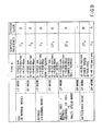
- the servo circuit 12 drives the drum motor 17 and capstan motor 19 as per the mode byte data and status byte data so that the rotating speed N of the rotary drum 60 reaches 2000 rpm and the running speed Vt of the magnetic tape attains 4.075 mm/sec.
- the drum motor 17 and capstan motor 19 are likewise driven so that the rotating speed N of the rotary drum 60 reaches 4000 rpm and the running speed V, of the magnetic tape 10 attains 8.150 mm/sec.
- the magnetic tape 10 runs by the amount of a single turn of the type A drum while the rotary drum 60 makes two turns. Because the magnetic heads 61A and 61B are staggered when in position, the recording signal is supplied to the magnetic heads 61A and 61B during the first of the two turns made by the rotary drum 60 in order to form recording tracks consecutively in the format specific to the currently configured digital audio tape recorder.
- the servo circuit 12 drives the drum motor 17 and capstan motor 19 so that the rotating speed N of the rotary drum 60 reaches 4000 rpm and the running speed V, of the magnetic tape 10 attains 4.075 mm/sec in LP mode or 8.150 mm/sec in SP mode.
- the servo circuit 12 provides tracking control by selecting a suitable tracking control means for semi-NT servo operation or ATF servo operation.
- the servo circuit 12 drives the drum motor 17 and capstan motor 19 so that the rotating speed N of the rotary drum 60 reaches 4000 rpm and the running speed V t of the magnetic tape 10 attains 8.150 mm/sec.
- the rotary drum 60 and the magnetic tape 10 are driven at twice normal recording speeds while the rotating speed of the rotary drum 60 is held at the same ratio of normal recording relative to the running speed of the magnetic tape 10. This makes it possible to generate the recording signal and process the playback signal S RF at two times their respective speeds of normal recording, thereby achieving multiple speed recording and playback.
- the servo circuit 12 drives the drum motor 17 and capstan motor 19 so that the running speed V t of the magnetic tape 10 and the rotating speed N of the rotary drum 60 reach their respective values of multiple speed recording/playback mode.
- the servo circuit 12 drives the drum motor 17 and capstan motor 19 at predetermined speeds in accordance with the control data D CONT .
- the digital signal processing circuit 8 switches the operation mode based on the control data D CONT stored in the memory circuit 44 in the same manner as with the type A. And as with the type A, the rotary drum reference signal DREF is generated and the playback signal S RF and recording signal S REC are processed consecutively in accordance with the reference clock signal F S and with the system clock signal S SYS at the frequency A (MHz) in normal mode, and according to the reference clock signal 2F S and to the system clock signal S SYS at the frequency B (MHz) in multiple speed recording/playback mode.
- type B configuration like the type A, effectively avoids data losses during multiple speed recording and playback.
- the recording signal generation circuit 50 generates, during the first of the two turns made by the rotary drum 60, the recording signal S REC with a transmission rate of 4.704 Mbps in LP mode, or 9.408 Mbps in SP mode.
- the digital audio tape recorder of the type B like its counterpart of the type A, records audio signals successively in the predetermined format.
- the playback signal S RF is demodulated at the timing at which the magnetic heads 61A and 61B scan the magnetic tape 10.
- the signal is consecutively processed in units of blocks for audio signal demodulation.
- the recording signal S REC with a transmission rate of 9.408 Mbps is generated to maintain compatibility with normal recording mode.
- the type B configuration described above allows the clock signal S FS and the system clock signal S SYS to be switched in terms of frequency so as to effectively avoid data losses for multiple speed recording and playback.
- a third embodiment of the invention of type C rotary drum configuration, comprises the rotary drum 60 of the type B configuration (Fig. 8) with no stagger provided between the magnetic heads 61A and 61B positioned thereon.
- the magnetic tape 10 is scanned alternately by magnetic heads 62A and 62B at intervals of half-turns made by the rotary drum 60.
- the servo circuit 12 drives the drum motor 17 and capstan motor 19 so that the rotating speed N of the rotary drum 60 reaches 1000 rpm and the running speed V t of the magnetic tape 10 attains 4.075 mm/sec.
- the drum motor 17 and capstan motor 19 are driven so that the rotating speed N of the rotary drum 60 reaches 2000 rpm and the running speed V t of the magnetic tape 10 attains 8.150 mm/sec.
- An appropriate recording signal is then supplied at the timing at which the magnetic heads 62A and 62B alternately scan the magnetic tape 10, whereby recording tracks are formed consecutively in a predetermined format.
- the drum motor 17 In normal playback mode, the drum motor 17 is driven so that the rotating speed N of the rotary drum 60 reaches 4000 rpm; the capstan motor 17 is driven so that the running speed of the magnetic tape 10 attains 4.075 mm/sec in LP mode and 8.150 mm/sec in SP mode.
- the running speed of the magnetic tape 10 relative to the rotary drum 60 drops to half of the value for recording in both LP mode and SP mode.
- the servo circuit 12 selects semi-NT servo operation for tracking control.
- the servo circuit 12 drives the drum motor 17 and capstan motor 19 so that the rotating speed N of the rotary drum 60 reaches 4000 rpm and the running speed V t of the magnetic tape 10 attains 16.30 mm/sec.
- the rotating drum 60 turns at four times its normal speed and the magnetic tape 10 runs at twice its normal speed while the rotating speed of the drum 60 is held at the same ratio of recording to the running speed of the magnetic tape 10.
- the servo circuit 12 drives the drum motor 17 and capstan motor 19 so that the running speed V t of the magnetic tape 10 and the rotating speed N of the rotary drum 60 reach their respective values for multiple speed recording or playback.
- the servo circuit 12 drives the drum motor 17 and capstan motor 19 at appropriate speeds in accordance with the control data D CONT .
- the digital signal processing circuit 8 switches the operation mode based on the control data D CONT from the memory circuit 44 in the same manner as with the type A. And as with the type A, the rotary drum reference signal DREF is generated and the playback signal S RF and recording signal S REC are processed consecutively in accordance with the reference clock signal F S and with the system clock signal S SYS at the frequency A (MHz) in normal mode, and according to the reference clock signal 2F S and to the system clock signal S SYS at the frequency B (MHz) in multiple speed recording/playback mode.
- type C configuration like the type A, effectively avoids data losses during multiple speed recording and playback.
- the magnetic tape 10 may be recorded or played back at four times the speed of the mode in effect.
- the magnetic tape 10 may be recorded or played back at twice the speed of recording.
- the digital signal processing circuit 8 switches the transmission rates of the recording signal S REC in accordance with the rotating speed of the rotary drum 60. This allows the audio signal to be recorded successively in the suitable format as with the type A.
- the type C configuration described above allows the clock signal S FS and the system clock signal S SYS to be switched in terms of frequency so as to effectively avoid data losses for multiple speed recording and playback.
- a fourth embodiment corresponds to a type D configuration.
- the rotary drum 60 whose construction is the same as the drum of the type C rotates at a speed lower than the speed of the type C.
- the servo circuit 12 drives the rotary drum 60 and capstan motor 19 under the same conditions as with the type C.
- the servo circuit 12 drives the capstan motor 19 so that the rotating speed N of the rotary drum 60 reaches 2000 rpm and the running speed V t of the magnetic tape 10 attains 4.075 mm/sec in LP mode or 8.159 mm/sec in SP mode.
- the rotating speed of the rotary drum 60 relative to the magnetic tape 10 is held at half of the value with the type C.
- the playback signal SRF is obtained by semi-NT servo operation; where a magnetic tape 10 recorded in SP mode is played back, the playback signal S RF is acquired by ATF servo operation.
- the servo circuit 12 drives the drum motor 17 and capstan motor 19 so that the rotating speed N of the rotary drum 60 reaches 2000 rpm and the running speed V t of the magnetic tape 10 attains 8.150 mm/sec.
- the magnetic heads 61A and 61B scan the magnetic tape 10 at the same timing for recording in SP mode. In this manner, ATF servo operation is used to implement the recording or playback process.
- the digital signal processing circuit 8 In the same manner as with the type A, the digital signal processing circuit 8 generates the rotary drum reference signal DREF and processes the playback signal S RF and recording signal successively in accordance with the reference clock signal F S and with the system clock signal S SYS at the frequency A (MHz), or according to the reference clock signal 2F S and to the system clock signal S SYS at the frequency A (MHz).
- the type P configuration like the type A, effectively avoids data losses during multiple speed recording and playback.
- the digital signal processing circuit 8 generates the recording signal S REC with a transmission rate corresponding to the rotary speed of the rotary drum 60 in normal mode as well as in multiple speed recording/playback mode. This allows the audio signal to be recorded successively in the suitable format as with the type A.
- the type D configuration described above allows the clock signal 2F S and the system clock signal S SYS to be switched in terms of frequency so as to effectively avoid data losses for multiple speed recording and playback.
- multiple speed recording and playback are carried out by use of the digital audio tape recorder having a rotary drum diameter of 30 or 15 mm.
- the invention may be practiced with a digital audio tape recorder having other rotary drum diameters including 20 or 10 mm.
- the above-mentioned embodiments allow the audio signal to be recorded or reproduced at twice the speed of recording.
- the invention may be practiced with other embodiments in which the audio signal is recorded or reproduced at various speeds including one and one half times the speed of recording.
- the foregoing embodiments are constructed to record and playback the audio signal.
- the invention may be practiced with magnetic recording and playback equipment such as an external memory device for use by computing apparatus, the device handling data to be computed.
- This type of memory device allows data to be recorded and reproduced with no losses of data in accordance with the transmission rate of the computing apparatus configured. In this manner, the invention widens the scope of use of the magnetic recording and playback equipment when applied thereto.
- the principles of the invention can otherwise be practiced with various kinds of apparatus including a playback or recording-dedicated digital audio tape recorder and magnetic recording devices for recording and playing back data other than audio signals.
Abstract
Description
- The present invention generally relates to digital signal processing circuits. More particularly, the invention relates to a digital signal processing circuit employed in a magnetic recording and playback apparatus for recording and playing back digital audio signals.
- A digital audio tape recorder comprises one type of magnetic recording and playback apparatus having a rotary drum arrangement to record and playback digital audio signals. The digital audio tape recorder is capable of converting an audio signal comprising analog elements into a digital signal for recording and playback. This feature makes it possible to effectively avoid degradation in sound quality while the audio signal is being recorded and playback with high degrees of density.
- One way to improve the ease of use and recording quality of the digital audio tape recorder is to switch its recording and playback speeds. This switching, as with conventional analog signal tape recorders, allows magnetic tapes to run at multiples of the standard speed so that the tapes may be run, for example two times, three times, or four times as fast as the standard speed.
- Switching the recording and playback speeds of the digital audio tape recorder affords another benefit: widening of the scope of its use. For example, the digital audio tape recorder can also function as an external memory device for use with a computing apparatus. In operation, the recorder records and plays back serial digital data in place of digital audio signals at a speed compatible with the data transmission rate of the computer apparatus.
- However, prior art digital audio tape recorders of this kind inevitably lose some digital data in their digital signal processing circuit if the magnetic tape running speeds are simply switched in the same manner as they are on conventional tape recorders. In such digital audio tape recorders, it has been practically impossible to overcome the problems resulting from switching of the recording and playback speeds.
- The present invention provides a digital signal processing circuit allowing digital signals to be recorded and played back at various recording and reproducing speeds while effectively preventing the occurrence of data loses.
- To this end, in an embodiment, the invention provides a digital tape recorder with a digital signal processing circuit and a magnetic tape wound around a rotary drum, the tape running at a constant speed relative to a rotating speed of the drum, the drum rotating speed and the tape running speed being changed in accordance with predetermined control data DCONT so that a digital signal entering a digital signal input/output circuit is converted by a recording signal processing circuit to a recording signal for recording onto the magnetic tape and/or a playback signal SRF from the magnetic tape is converted by a playback signal demodulation circuit to the digital signal for output via the digital signal input/output circuit; operating frequencies of the digital signal input/output circuit, the recording signal processing circuit, and the playback signal demodulation circuit being switched in accordance with the control data DCONT.
- These and other features as well as the nature, principal, and utility of the invention will become more apparent from the following detailed description and accompanying drawings.
-
- Fig. 1 is a block diagram of a digital signal processing circuit that can be used in conjunction with the tape recorder circuit of Fig. 2.
- Fig. 2 is a block diagram of a digital tape recorder.
- Fig. 3 is a table illustrating a mode byte used in conjunction with the preferred embodiments of the invention.
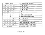
- Fig. 4 is a table depicting data of a status byte used in conjunction with preferred embodiments of the invention.
- Fig. 5 is a schematic plan illustrating how a type A rotary drum can be constructed.
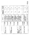
- Fig. 6 is a table that describes how the type A rotary drum of Fig. 5 functions.
- Fig. 7 is a signal waveform chart associated with the rotary drum of Figs. 5 and 6.
- Fig. 8 is a schematic plan showing how type B, C, and D drums can be constructed.
- Figs. 9 through 11 are tables that describe how the rotary drums of Fig. 8 function.
- In Figs. 1 and 2 there is illustrated in block diagram form a circuit for a digital audio tape (DAT)
recorder 1 embodying principles of the invention. - Fig. 2 illustrates the overall arrangement of the
DAT recorder 1. Fig. 1 illustrates a digitalsignal processing circuit 8 that can be used in the arrangement of Fig. 2. As is known, a DAT recorder can be used to convert analog stereo audio signals into digital signals for recording purposes. - In one aspect of its operation, the
DAT recorder 1 has aninput display circuit 2 that outputs operation data PSOU in response to an operator's actions and also switches on or off suitable displays on a display panel (not shown) in accordance with appropriate control data. The operator's input can be made via a keyboard and the display panel can comprise liquid crystal display (LCD) elements. - The DAT recorder has three basic modes: recording, after recording, and playback. Further, the DAT recorder has a long play (LP) mode and a standard play (SP) mode discussed further below.
- In recording, a
system control circuit 6 generates control data PCONT, in accordance with the operation data PSOU and further configuration data, which configuration data is established in advance to reflect the configuration of theDAT recorder 1, such as the selected rotary drum arrangement. The control data DCONT is referenced when recording digital audio signals in response to the operators actions. - In playback, the control data DCONT is generated by the
system control circuit 6 in accordance with status byte data supplied by the digitalsignal processing circuit 8, the operation data DSOU, and the configuration data. - The control data DCONT is thus used for two purposes: to switch the operation mode of the
DAT recorder 1 in response to the operators actions and to effect playback of digital audio signals from amagnetic tape 10 in accordance with the recording format recorded thereon. - The control data PCONT preferably comprises serial data in the form of a byte, which byte is used both as a mode byte and as a status byte, each byte comprising eight (8) bits.
- In Fig. 3, a table is provided to illustrate the correlations between the various bits of the mode byte and the various modes of the
DAT recorder 1. As illustrated, the two highest-order bits in the mode byte identify the diameter of therotary drum 16 as well as magnetic head rotation. In the one embodiment, a two bit value is set in aservo circuit 12 in accordance with the configuration of therotary drum 16 and other configuration settings, the two bit value being output as the two highest-order bits from thesystem control circuit 6. - Preferably, the two-bit values "00", "01", "10", and "11" indicate whether the configuration of the
rotary drum 16 and the magnetic heads of theDAT recorder 1 is of type "A", "B", "C", or "D", respectively. These various configuration types are discussed below. - The third highest-order bit of the mode byte preferably identifies whether the
DAT recorder 1 is in its test signal recording mode. When the third highest order bit is set to "1", it preferably means that theDAT recorder 1 is in its test signal recording mode. - The fourth highest order bit of the mode byte preferably identifies whether the
DAT recorder 1 is in a recording mode. When the fourth highest order bit is set to a "1", it preferably means that theDAT recorder 1 is in its recording mode. - The fifth highest order bit of the mode byte preferably indicates whether the
DAT recorder 1 is in an after-recording mode. When the fifth highest order bit is set to a "1", it preferably means that theDAT recorder 1 is in its after recording mode. - The sixth highest order bit of the mode byte preferably indicates whether the
DAT recorder 1 is in normal speed mode or, multiple speed mode, the normal speed mode being a mode in which recording or playback is undertaken at a normal tape speed, and the multiple speed mode being a mode in which recording or playback is undertaken at tape speeds that are multiples of the normal tape speed. A setting of the sixth highest order bit to a "0" preferably means that theDAT recorder 1 will rewind or playback in a normal speed mode while a setting of the sixth highest order bit to a "1" preferably means that theDAT recorder 1 will rewind or playback in a multiple speed mode. - The table of Fig. 3 should be self explanatory. However, it should be noted that a hyphen is inserted whenever the value of a particular bit is not of concern.
- As an example, a mode byte of "--001000", preferably means that the
DAT recorder 1 is in its after recording mode and the tape speed is set to a normal mode. A mode byte of "--001100" preferably means that theDAT recorder 1 is in it after recording mode and the tape speed is set to the multiple speed mode. - Similarly, a mode byte of "--01-0--" or "--01-1-1--" preferably means that the
DAT recorder 1 is in its recording mode and the tape speed is set to either the normal mode or multiple speed mode respectively. A mode byte of "--01--0-" preferably indicates that theDAT recorder 1 has started recording while a mode byte of "--01--1-" preferably indicates that theDAT recorder 1 is ready for recording. - Referring now to Fig. 4, the status byte is generated during recording by the
system control circuit 6 in accordance with the control data DSOU. When thetape recorder 1 is in its playback mode or after-recording mode, the status byte is generated by the digitalsignal processing circuit 8 in accordance with sub-code data recorded on themagnetic tape 10. - The two highest-order bits of the status byte, also referred to as DFS, represent a sampling frequency fS of the digital audio signal. The next two highest-order bits indicate the number of channels over which audio signals are recorded or played back by the digital
audio tape recorder 1. - The fifth and the sixth highest-order bits identify the type of quantization in effect when an audio signal is converted to a digital audio signal and vice-versa. The seventh and the eighth highest-order bits identify a track pitch value TP.
- Accordingly, a status byte of "100-01--" preferably means that a two-channel audio signal subjected to a 12-bit nonlinear quantization at a sampling frequency of 32 KHz is recorded in long play (LP) mode on the magnetic tape, or is played back therefrom in LP mode. A status byte of "01----01" preferably means that a magnetic tape recorded at 1.5 times the normal track pitch is reproduced in 1.5-fold track pitch mode. A status byte other than "100-01--" or "01----01" means that the magnetic tape is recorded in standard play (SP) mode, or the magnetic tape recorded in SP mode is played back.
- With reference again to Fig. 2, the
DAT recorder 1 also includes amechanical control circuit 11 that controls a tape cassette loading/ejecting mechanism, a magnetic tape loading mechanism, and other parts. The control is formulated in accordance with the control data DCONT provided by thesystem control circuit 6. - A
servo circuit 12 is provided that drives areel motor 14 according to the control data DCONT, thereby rotating the reels of a magnetic tape cassette, not shown, at a predetermined speed. Theservo circuit 12 also generates a switching pulse signal SWP whereby the signal level is switched on each revolution of therotary drum 16 and, as per the control data DCONT, drives adrum motor 17 so that the switching pulse signal SWP reaches a predetermined phase relative to a rotating drum reference signal DREF. - A rotary drum reference signal DREF preferably comprises a reference signal having a duty factor of 50%, the signal being repeated at interleaving intervals of 60 msec in LP mode and 30 msec in SP mode during normal recording or reproduction. In view of the reference signal DREF, and as the control data DCONT, the
rotary drum 16 is controlled to rotate by an appropriate amount in each interleaving period. - In addition, the
servo circuit 12 drives acapstan motor 19 with reference to a tracking error signal provided by trackingcontrol circuit 18, thereby providing tracking control while letting the magnetic tape run at a speed dictated by the control data DCONT. In this manner, theservo circuit 12 switches the running speed of themagnetic tape 10 and the rotating speed of therotary drum 16 in accordance with the control data DCONT, digitally records an audio signal on thetape 10 in the format specified by the operator's action, and plays back the digital audio signal from thetape 10 in view of the recording format recorded thereon. - Referring to Fig. 5, a first embodiment is constructed to be of the type A configuration. That is, a pair of
magnetic heads rotary drum 16. Thedrum 16 preferably has a diameter of 30 mm. Themagnetic tape 10 is then wound around a portion of therotary drum 16 and held there against byrollers drum 16, as illustrated. - Referring to Fig. 6, it can be appreciated that the
servo circuit 12 switches theDAT recorder 1 between the various operation modes according to the control data DCONT. For long-play (LP) recording in the recording mode, theservo control circuit 12 drives thedrum motor 17 andcapstan motor 19 so that the rotating speed N of therotary drum 16reaches 1000 rpm and the running speed Vt of themagnetic tape 10 attains a speed of 4.075 mm/sec. - For standard-play recording in the recording mode, the
servo circuit 12 drives thedrum motor 17 andcapstan motor 19 so that the rotating speed N of therotary drum 16reaches 2000 rpm and the running speed Vt of themagnetic tape 16 reaches 8.150 mm/sec. In this manner, scanning loci are formed successively on themagnetic heads - For playback in normal mode, the
drum motor 17 is driven so that the rotating speed N of therotary drum 16reaches 2000 rpm, while thecapstan motor 19 is driven so that the running speed reaches 4.075 mm/sec in LP mode and 8.150 mm/sec in SP mode. - Thus in playback in normal mode, the
rotary drum 16 rotates at the same timing as for SP mode recording in normal mode. Where amagnetic tape 10 recorded in SP mode is reproduced, thetape 10 is controlled to run by one recording track per cycle of scanning by themagnetic heads - During SP mode playback, the
servo circuit 12 provides tracking control using the so-called automatic track finding (ATF) method as per the tracking error signal from thetracking control circuit 18. When amagnetic tape 10 recorded in LP mode is played back, therotary drum 16 rotates at twice the recording speed. Accordingly, themagnetic heads magnetic tape 10 twice while the tape runs over one recording track. - In this way, the digital
signal processing circuit 8 repeatedly acquires the playback signal SRF during LP mode playback. Selective processing of the playback signal SRF allows digital audio signals to be played back as desired. Meanwhile, theservo circuit 12 provides tracking control (so-called semi-NT servo) as per the tracking error signal from thetracking control circuit 18 so that themagnetic heads magnetic tape 10. - In multiple speed recording or playback (i.e., recording or playback in multiple speed mode), the
servo circuit 12 drives thedrum motor 17 andcapstan motor 19 so that the rotating speed N of therotary drum 16reaches 2000 rpm and the running speed Vt of themagnetic tape 10 reaches 8.150 mm/sec. In this way, with therotary drum 16 rotating at the same speed as in LP recording mode relative to themagnetic tape 10, theservo circuit 12 provides control so that therotary drum 16 and themagnetic tape 10 in multiple speed mode operate two times as fast as in normal recording mode. Thus in multiple speed recording/playback mode, the recording signal is supplied to themagnetic heads - In the after-recording mode, the
servo circuit 12 controls thedrum motor 17 andcapstan motor 19 so that themagnetic tape 10 runs and therotary drum 16 rotates at the same speeds as in two times speed recording/playback mode. That is, in after-recording SP mode, theservo circuit 12 drives therotary drum 16 andcapstan motor 19 at the same timing as in normal mode; in LP mode, theservo circuit 12 drives these parts at the same timing as in two times speed recording/playback mode for ATF servo tracking control. - Also included is an audio
signal conversion circuit 21 that comprises an analog-to-digital conversion circuit, a digital-to-analog conversion circuit and a digital filter circuit, the circuits operating in reference to a clock signal SFS from the digitalsignal processing circuit 8. In recording mode, a stereo audio signal SIN entering the digitalaudio tape recorder 1 is converted to the digital audio signal DAU for output to the digitalsignal processing circuit 8. In playback mode, the digital audio signal DAU from the digitalsignal processing circuit 8 is converted by the audiosignal conversion circuit 21 into an analog signal SOUT for output. - Meanwhile, in recording mode, the digital
signal processing circuit 8 converts the digital audio signal DAU to the recording signal SREC as per the control data DCONT. The recording signal SREC is output via a recording andplayback amplifier circuit 24 to themagnetic heads magnetic tape 10 in the format specific to the currently configured digital audio tape recorder. - Switching from recording mode to playback mode is achieved in accordance with the control data DCONT and as per the sub-code data obtained by demodulating a playback signal SRF retrieved from the tape. After the switch, the playback signal SRF is converted to the digital audio signal DAU for output to the audio
signal conversion circuit 21. The playback signal SRF from themagnetic heads - In the digital
signal processing circuit 8, as depicted in Fig. 1, a control data I/O circuit 20 places the control data DCONT, from thesystem control circuit 6 into a predetermined area of amemory circuit 44 via a bus arrangement and amemory interface circuit 42. - In playback mode, the control data I/
O circuit 20 reads the status byte data from the sub-code data that was demodulated and placed in thememory circuit 44. Thecircuit 20 then sends the status byte data to thesystem control circuit 6. This causes the recording data recorded on themagnetic tape 10 to be retrieved therefrom and transmitted to thesystem control circuit 6. - In this manner, the
memory circuit 44, in recording mode, accommodates as the control data DCONT the status byte and mode byte generated by thesystem control circuit 6. In playback mode, thememory circuit 44 admits as the control data DCONT both the mode byte data generated by thesystem control circuit 6 and the status byte data made up of the recording data recorded on themagnetic tape 10. - In the foregoing setup, the digital
signal processing circuit 8, in recording mode, outputs the recording signal SREC in response to the operator's action and in accordance with the configuration of therotary drum 16. In playback mode, the digitalsignal processing circuit 8 demodulates the playback signal SRF according to the rotary drum configuration and the recording format. - A clock
signal generation circuit 30 drivescrystal oscillators - The clock
signal generation circuit 30 waveform-rectifies the oscillation output signal at 49.152 MHz into a reference clock signal SOSC. This clock signal is output to a clocksignal sampling circuit 33 to sample a playback clock signal. - The clock
signal generation circuit 30 converts each of the oscillation output signal with the frequencies of 22.5792 and 49.152 MHz into a reference clock signal 2FS which is twice the sampling frequency of 48, 44.1 or 32 KHz specific to the digitalaudio tape recorder 1. The reference clock signal 2FS is selectively output in accordance with the high-order two-bit data DFS in the status byte. Then, a dividingcircuit 35 divides the applicable reference clock signal 2FS in half to generate the reference clock signal FS with the sampling frequency of 48, 44.1 or 32 KHz. - A
selection circuit 36 switches its contacts according to a switching signal SEL generated by the digitalsignal processing circuit 8 based on the control data DCONT. In this way, thecircuit 36 outputs the reference clock signal FS or 2FS in normal mode or in multiple speed recording/playback mode, respectively, for selective output to the audio signal conversion circuit 21 (Fig. 2), an I/O circuit 40, or the digital signal I/O circuit 41. - In turn, the clock
signal generation circuit 37 drives thecrystal oscillator 38 to generate an oscillation output signal with a frequency of 18.826 MHz. Thecircuit 37 then divides the oscillation output signal to generate system block signals with frequencies A and B (MHz). - A
selection circuit 39 switches its contacts according to the switching signal SEL generated by the digitalsignal processing circuit 8. In this way, thecircuit 36 outputs a system clock signal SSYS at the frequency A or B (MHz) in coordination with theselection circuit 36 for selective output to the digital signal I/O circuit 41, control data I/O circuit 20,memory interface circuit 42,memory circuit 44, recordingsignal generation circuit 50, reproducedsignal processing circuit 48, and error detection and correction circuit (ECC) 46. - In this manner, the recording and playback section of the digital
audio tape recorder 1 switches the reference clock signals 2FS and FS for output. This in turn switches the operating frequencies of the audiosignal conversion circuit 21, I/O circuit 40 and digital signal I/O circuit 41 to process the audio signal at the reference sampling signal of 48, 44.1 or 32 KHz. In multiple speed recording or playback mode, the audio signal is processed at two times the reference frequency of 48, 44.1 or 32 KHz. - In normal mode or in double multiple speed recording/playback mode, the system clock signal SSYS is switched to the frequency A or B (MHz). This in turn switches the operating frequencies of the digital signal I/
O circuit 41, control data I/O circuit 20,memory interface circuit 42,memory circuit 44, recordingsignal generation circuit 50, playbacksignal processing circuit 48, and error detection andcorrection circuit 46. Thus in multiple speed recording/playback mode, the digital audio signal DAU and playback signal SRF are processed twice as fast as in normal recording mode. Accordingly, the digitalaudio tape recorder 1 records and playback data at two times the normal speed while effectively avoiding the losses thereof. - The frequency B (MHz) of the system clock signal SSYS is set to be about one and a half times the frequency A (MHz) thereof. The frequency B is in practical terms sufficient to convert the digital audio signal DAU to the recording signal SREC in half of the normal mode cycle, the audio signal DAU in this case having being sampled in multiple speed recording/playback mode at the frequency twice the normal mode sampling frequency. In addition, the frequency B when selected results only in a modest, practically reasonable increase in overall power consumption by the digital
signal processing circuit 8. - The I/
O circuit 40 converts to a predetermined format a digital audio signal RX that is input in an AES/EBU format to the digitalaudio tape recorder 1, and outputs the converted signal to the digital signal I/O circuit 41. At the same time, the digital audio signal from the digital signal I/O circuit 41 is output after conversion to a digital audio signal TX in the AES/EBU format. - In this manner, the digital
audio tape recorder 1 records and reproduces the digital audio signals TX and RX in the AES/EBU format in addition to the audio signals SIN and SOUT, which are analog signals. - The digital signal I/
O circuit 31 loads the control data DCONT from an assigned area of thememory circuit 44 at a predetermined timing via thememory interface circuit 42. Based on the control data DCONT thus acquired, thecircuit 31 switches the operation mode. - Furthermore, the digital signal I/
O circuit 41 counts successive pulses of the clock signal SFS from theselection circuit 36 using an internal counter circuit, not shown. The digital signal I/O circuit 41 thus generates the rotary drum reference signal DREF with an interleaving period of 60 msec for normal LP recording mode, or with an interleaving period of 30 msec for normal SP recording mode and in multiple speed recording/playback mode. - In recording mode, the digital signal I/
O circuit 41 selectively inputs the digital audio signal from the I/O circuit 40 or from the audiosignal conversion circuit 36, and places the signal consecutively into thememory circuit 44 with reference to the count value in the counter circuit. This divides the digital audio signal into blocks in the interleaving period for storage into thememory circuit 44. - For LP mode recording and SP mode recording in normal mode, the
memory circuit 44 accommodates the digital audio signal in blocks of 30 and 60 msec, respectively, the signal having been sampled in accordance with the reference clock signal FS. For LP mode recording in multiple speed recording/playback mode, the digital audio signal is divided into blocks of 30 msec and stored consecutively into thememory circuit 44, the signal having been sampled using thereference clock signal 2FS which is twice the clock signal FS in frequency. - With the digital audio signal consecutively placed into assigned areas of the
memory circuit 44 in reference to the count value in the internal counter circuit, the digital signal I/O circuit 41 interleaves the signal for one interleaving period. - In playback mode, the digital signal I/
O circuit 41 loads from thememory circuit 44 the digital audio signal in units of blocks according to the count value of the counter circuit. After reverse interleaving, the digital audio signal is output consecutively to the I/O circuit 40 and audiosignal conversion circuit 36 in accordance with the clock signal SFS. - As with the digital signal I/
O circuit 41, the error detection andcorrection circuit 46 loads the control data DCONT at an appropriate timing from thememory circuit 44. Based on the control data, thecircuit 41 switches the operation mode. - In recording mode, the digital audio signal is loaded consecutively from the
memory circuit 44. The signal is divided into blocks, each block being given a parity code made up of an internal and an external code for error correction. These parity codes are placed in thememory circuit 44. - In playback mode, the playback data is loaded consecutively from the
memory circuit 44 via the playbacksignal processing circuit 48. The playback data is subjected to error correction and detection before its storage back to thememory circuit 44. - As shown in Fig. 7, upon playback in normal mode, the error detection and
correction circuit 46 utilizes, along with the playbacksignal processing circuit 48, the scheme disclosed in Japanese Patent Application No. 1-197827 and U.S. Patent No. 4,630,272, the teachings of which are fully incorporated by reference, for error detection and correction, using twice each of codes C1 and C2 comprising internal and external codes for error correction. Upon playback in multiple speed recording/playback mode, the error correction based on the code C2 is omitted once. This makes it possible to secure a period of processing time practically long enough for error correction when the system clock signal SSYS is switched to the frequency B(MHz). - In the setup above, the playback signal SRF (Fig.7(A)) obtained via the
magnetic heads signal processing circuit 48 using the code C1 (Fig. 7(B)). The error-free reproduced signal is stored into thememory circuit 44. - In the interleaving period that follows, the playback data in the
memory circuit 44 is subjected to error detection and correction by the error detection andcorrection circuit 46 using the codes C2, C1 and C2 in succession (Fig. 7(C)). In the next interleaving period, the error-free, playback data is output via the digital signal I/O circuit 41 (Fig. 7 (P)). - In multiple speed recording/playback mode, the error detection and correction process by the error detection and
correction circuit 46 based on the first code C2 is omitted. This makes it possible to playback at multiple speed the digital audio signal that has been error-corrected with a degree of accuracy high enough for practical purposes. - In Fig. 7, reference characters A and B are the playback signals SRF obtained from the
magnetic beads reference numerals - As with the digital signal I/
O circuit 41, the recordingsignal generation circuit 50 loads the control data DCONT from thememory circuit 44 at a predetermined timing. The control data is used to switch the operation mode. - In recording mode, the digital audio signal is read from the
memory circuit 44 in a predetermined sequence of blocks together with their parity codes. The blocks of the signal are subjected to 8-to-10 modulation. - After converting the modulated signal to serial data, the recording
signal generation circuit 50 adds thereto a pilot signal for AFT tracking control and a synchronizing signal. The supplemented signal is then output to themagnetic heads playback amplifier circuit 24 at the timing at which theheads magnetic tape 10. - The signal is then interleaved in units of blocks via the recording
signal generation circuit 50 to become the recording signal SREC which is modulated together with the parity codes attached. This recording signal SREC is output to themagnetic heads magnetic tape 10. - At this point, the recording
signal generation circuit 50 outputs consecutively the modulated recording signal SREC at a transmission rate of 4.704 Mbps or 9.408 Mbps in LP mode or SP mode, respectively, for normal mode recording in reference to the reference clock signal SOSC. This allows the digital audio signal to be successively recorded in the format specific to LP or SP mode and in accordance with the speeds at which therotary drum 16 and themagnetic tape 10 operate. - For multiple speed recording or playback in LP mode, the
rotary drum 16 rotates at twice its speed of normal mode. Thus the recording signal SREC is output at a transmission rate of 9.408 Mbps, twice the normal mode rate. In this manner, the digital audio signal is recorded in the same format as for normal recording or playback. - In normal mode, the digital audio signal is sampled according to the reference clock signal FS before being divided into blocks. The signal in blocks is converted to the recording signal SREC by the digital signal I/
O circuit 41,memory interface circuit 42,memory circuit 44, error detection andcorrection circuit 46 and recordingsignal generation circuit 50, the circuits operating in reference to the system clock signal SSYS at the frequency A (MHz). - In multiple speed recording/playback mode, the digital audio signal is sampled in accordance with the reference clock signal 2FS before being divided into blocks, the frequency of the signal 2FS being two times that of the clock signal FS. The signal in blocks is converted to the recording signal SREC by the digital signal I/
O circuit 41,memory interface circuit 42,memory circuit 44, error detection andcorrection circuit 46 and recordingsignal generation circuit 50, the circuits operating in reference to the system clock signal SSYS whose frequency is about one and one half times the frequency A (MHz). The setup above makes it possible to effectively avoid degradation in sound quality when, say, an audio signal reproduced in multiple speed recording/reproducing mode is input to the audiosignal conversion circuit 21 for recording. - Where the digital audio signal is directly input for multiple speed recording or playback, the foregoing setup also allows the signal to be recorded while effectively avoiding data losses.
- In playback mode, the recording
signal generation circuit 50 stops the output of the recording Signal SREC according to the control data DCONT. - The clock
signal sampling circuit 33 in playback mode samples a playback clock signal CK from the playback signal SRF available via the recording andplayback amplifier circuit 24 in accordance with the clock signal SOSC. The playback clock signal CK is output to the playbacksignal processing circuit 48. - For recording, the playback
signal processing circuit 48 stops its operation based on the control data DCONT; for playback, thecircuit 48 subjects the playback signal SRF to 10-to-8 demodulation in reference to the playback clock signal CK. The resulting playback data is placed successively into assigned areas of thememory circuit 44. - When placing the playback data into the
memory circuit 44, the playbacksignal processing circuit 48 detects error in the data using the code C1 comprising external codes for error correction. The result of the error detection is stored in thememory circuit 44. - Where a
magnetic tape 10 recorded in LP mode is played back in normal mode, the reproducedsignal processing circuit 48 performs NT servo operation. This causes one block of the playback signal SRF, which is output twice, to be demodulated by the scheme disclosed in Japanese Patent Laid-open No. 63-205861 and U.S. Patent No. 4,862,297, the teachings of which are fully incorporated by reference. The reproduced data is thus demodulated reliably. - After demodulation, the played back data is stored temporarily in the
memory circuit 44. The data is then corrected for error by the error detection andcorrection circuit 46, and is consecutively output via the digital signal I/O circuit 41. In this manner, the digital audio signal recorded on themagnetic tape 10 is played back therefrom. - In normal playback mode, the playback signal SRF having a transmission rate of 9.408 Mbps is processed consecutively in units of blocks by the
playbacksignal processing circuit 48,memory circuit 44, error detection andcorrection circuit 46,memory interface circuit 42 and digital signal I/O circuit 41, the circuits operating in accordance with the system clock signal SSYS at the frequency A (MHz), the blocks being output successively in synchronization with the reference clock signal FS. In multiple speed recording/playback mode, the playback signal SRF is processed consecutively in units of blocks by the playbacksignal processing circuit 48,memory circuit 44, error detection andcorrection circuit 46,memory interface circuit 42 and digital signal I/O circuit 41, the blocks being output successively in synchronization with the reference clock signal 2FS whose frequency is twice that of the signal F₅. This setup makes it possible to effectively avoid degradation in sound quality when, say, an audio signal played back at multiple speed is recorded also at multiple speed by another digital audio tape recorder whose construction control data is used to switch the operation mode. - At this point, in normal playback mode, the system clock signal SSYS at the frequency A (MHz) and the reference clock signal FS are selectively output from the
selection circuits selection circuits signal processing circuit 8 operates in reference to the selective output from theselection circuit - For normal mode recording, the digital audio signal DAU is input after being sampled via the audio
signal conversion circuit 21 using the reference clock signal FS. The digital audio signal DAU is divided into blocks by the digital signal I/O circuit 41 in one interleaving period of LP or SP mode, the blocks being interleaved and stored into thememory circuit 44. - The digital audio signal, after being stored in the
memory circuit 44, is given a parity code for each block thereof by the error detection andcorrection circuit 46. The signal is then converted to the recording signal SREC via the recordingsignal generation circuit 50 for output to themagnetic heads magnetic heads magnetic tape 10 in the recording format of LP or SP mode. - For multiple speed recording, the digital audio signal DAU is input after being sampled via the audio
signal conversion circuit 21 using the reference clock signal 2FS whose frequency is two times that of the clock signal FS. The digital signal I/O circuit 41 divides the digital audio signal DAU into blocks in half of the normal recording cycle, the blocks being interleaved and stored into thememory circuit 44. - The digital audio signal DAU stored in the
memory circuit 44 is converted successively to the recording signal SREC as in normal recording mode. At this point, the system clock signal SSYS is switched from frequency A (MHz; for normal mode) to frequency B (MHz), the latter being one and one half times the former. This in turn switches the rotating speed of therotary drum 16 and the running speed of themagnetic tape 10. As a result, the recording signal SREC is generated having a transmission rate twice that for normal recording, and is output at the timing at which themagnetic tape 10 is scanned by themagnetic heads - In normal playback mode, on the other hand, the recording
signal generation circuit 50 stops its operation, and the playbacksignal processing circuit 48 starts operating. - After the playback clock signal CK is sampled by the clock signal sampling circuit 52, the playback signal SRF is demodulated by the playback
signal processing circuit 48 in reference to the signal CK. - After demodulation, the played back data is stored temporarily into the
memory circuit 44. The data is then corrected for error by the error detection andcorrection circuit 46 and stored into thememory circuit 44. From thememory circuit 44, the error-free played back data is output consecutively via the digital signal I/O circuit 41. - At this point, in normal playback mode, the playback signal SRF is processed consecutively in units of blocks by the playback
signal processing circuit 48,memory circuit 44, error detection andcorrection circuit 46,memory interface circuit 42 and digital signal I/O circuit 41, the circuits operating in reference to the system clock signal SSYS at the frequency A (MHz), the blocks being output successively in synchronization with the reference clock signal FS via the digital signal I/O circuit 41. In multiple speed recording/playback mode, the playback signal SRF is processed consecutively in units of blocks by the playbacksignal processing circuit 48,memory circuit 44, error detection andcorrection circuit 46,memory interface circuit 42 and digital signal I/O circuit 41, the circuits operating in accordance with the system clock signal SSYS whose frequency is about one and one half times the frequency A (MHz), the blocks being output in synchronization with the reference clock signal 2FS whose frequency is twice that of the clock signal FS. - The setup above makes it possible to effectively avoid degradation in sound quality when, say, an audio signal played back at multiple speed is recorded also at multiple speed. Furthermore, this setup effectively eliminates data losses when the digital audio signal is to be input or output directly.
- In the manner described, the clock signal SFS and the system clock signal SSYS are switched in terms of frequency in multiple speed recording/playback mode. This makes it possible to effectively avoid data losses during multiple speed recording or reproducing of audio signal data.
- Referring to Fig. 8, a second embodiment comprises a
rotary drum 60 with a diameter of 15 mm making up the type B configuration. On therotary drum 60 aremagnetic heads magnetic tape 10 is wound around therotary drum 60 to form a 180-degree angle. - Referring to Fig. 9, for LP mode recording in normal mode, the
servo circuit 12 drives thedrum motor 17 andcapstan motor 19 as per the mode byte data and status byte data so that the rotating speed N of therotary drum 60reaches 2000 rpm and the running speed Vt of the magnetic tape attains 4.075 mm/sec. For SP mode recording in normal mode, thedrum motor 17 andcapstan motor 19 are likewise driven so that the rotating speed N of therotary drum 60reaches 4000 rpm and the running speed V, of themagnetic tape 10 attains 8.150 mm/sec. - With the type B configuration, the
magnetic tape 10 runs by the amount of a single turn of the type A drum while therotary drum 60 makes two turns. Because themagnetic heads magnetic heads rotary drum 60 in order to form recording tracks consecutively in the format specific to the currently configured digital audio tape recorder. - In normal playback mode, the
servo circuit 12 drives thedrum motor 17 andcapstan motor 19 so that the rotating speed N of therotary drum 60reaches 4000 rpm and the running speed V, of themagnetic tape 10 attains 4.075 mm/sec in LP mode or 8.150 mm/sec in SP mode. In LP mode or SP mode, theservo circuit 12 provides tracking control by selecting a suitable tracking control means for semi-NT servo operation or ATF servo operation. - In multiple speed recording/playback mode, the
servo circuit 12 drives thedrum motor 17 andcapstan motor 19 so that the rotating speed N of therotary drum 60reaches 4000 rpm and the running speed Vt of themagnetic tape 10 attains 8.150 mm/sec. - Thus for LP mode recording and playback in multiple speed recording/playback mode, the
rotary drum 60 and themagnetic tape 10 are driven at twice normal recording speeds while the rotating speed of therotary drum 60 is held at the same ratio of normal recording relative to the running speed of themagnetic tape 10. This makes it possible to generate the recording signal and process the playback signal SRF at two times their respective speeds of normal recording, thereby achieving multiple speed recording and playback. - In sub-code after-recording mode, the
servo circuit 12 drives thedrum motor 17 andcapstan motor 19 so that the running speed Vt of themagnetic tape 10 and the rotating speed N of therotary drum 60 reach their respective values of multiple speed recording/playback mode. - Thus with the type B configuration, as with the type A, the
servo circuit 12 drives thedrum motor 17 andcapstan motor 19 at predetermined speeds in accordance with the control data DCONT. - The digital
signal processing circuit 8 switches the operation mode based on the control data DCONT stored in thememory circuit 44 in the same manner as with the type A. And as with the type A, the rotary drum reference signal DREF is generated and the playback signal SRF and recording signal SREC are processed consecutively in accordance with the reference clock signal FS and with the system clock signal SSYS at the frequency A (MHz) in normal mode, and according to the reference clock signal 2FS and to the system clock signal SSYS at the frequency B (MHz) in multiple speed recording/playback mode. - Thus the type B configuration, like the type A, effectively avoids data losses during multiple speed recording and playback.
- In the digital
signal processing circuit 8, the recordingsignal generation circuit 50 generates, during the first of the two turns made by therotary drum 60, the recording signal SREC with a transmission rate of 4.704 Mbps in LP mode, or 9.408 Mbps in SP mode. - In this way, the digital audio tape recorder of the type B, like its counterpart of the type A, records audio signals successively in the predetermined format. In playback mode, the playback signal SRF is demodulated at the timing at which the
magnetic heads magnetic tape 10. As with the type A, the signal is consecutively processed in units of blocks for audio signal demodulation. - In multiple speed recording mode, the recording signal SREC with a transmission rate of 9.408 Mbps is generated to maintain compatibility with normal recording mode.
- The type B configuration described above allows the clock signal SFS and the system clock signal SSYS to be switched in terms of frequency so as to effectively avoid data losses for multiple speed recording and playback.
- A third embodiment of the invention, of type C rotary drum configuration, comprises the
rotary drum 60 of the type B configuration (Fig. 8) with no stagger provided between themagnetic heads magnetic tape 10 is scanned alternately bymagnetic heads rotary drum 60. - Referring to Fig. 10, for LP mode recording in normal mode, the
servo circuit 12 drives thedrum motor 17 andcapstan motor 19 so that the rotating speed N of therotary drum 60reaches 1000 rpm and the running speed Vt of themagnetic tape 10 attains 4.075 mm/sec. For SP mode recording in normal mode, thedrum motor 17 andcapstan motor 19 are driven so that the rotating speed N of therotary drum 60reaches 2000 rpm and the running speed Vt of themagnetic tape 10 attains 8.150 mm/sec. An appropriate recording signal is then supplied at the timing at which themagnetic heads magnetic tape 10, whereby recording tracks are formed consecutively in a predetermined format. - In normal playback mode, the
drum motor 17 is driven so that the rotating speed N of therotary drum 60reaches 4000 rpm; thecapstan motor 17 is driven so that the running speed of themagnetic tape 10 attains 4.075 mm/sec in LP mode and 8.150 mm/sec in SP mode. - Thus in normal playback mode, the running speed of the
magnetic tape 10 relative to therotary drum 60 drops to half of the value for recording in both LP mode and SP mode. Theservo circuit 12 then selects semi-NT servo operation for tracking control. - In multiple speed recording/playback mode, the
servo circuit 12 drives thedrum motor 17 andcapstan motor 19 so that the rotating speed N of therotary drum 60reaches 4000 rpm and the running speed Vt of themagnetic tape 10 attains 16.30 mm/sec. - Thus in multiple speed recording/playback mode, whether the target
magnetic tape 10 is recorded in LP mode or SP mode, therotating drum 60 turns at four times its normal speed and themagnetic tape 10 runs at twice its normal speed while the rotating speed of thedrum 60 is held at the same ratio of recording to the running speed of themagnetic tape 10. - In sub-code after-recording mode, the
servo circuit 12 drives thedrum motor 17 andcapstan motor 19 so that the running speed Vt of themagnetic tape 10 and the rotating speed N of therotary drum 60 reach their respective values for multiple speed recording or playback. - Thus with the type C configuration, as with the type A, the
servo circuit 12 drives thedrum motor 17 andcapstan motor 19 at appropriate speeds in accordance with the control data DCONT. - The digital
signal processing circuit 8 switches the operation mode based on the control data DCONT from thememory circuit 44 in the same manner as with the type A. And as with the type A, the rotary drum reference signal DREF is generated and the playback signal SRF and recording signal SREC are processed consecutively in accordance with the reference clock signal FS and with the system clock signal SSYS at the frequency A (MHz) in normal mode, and according to the reference clock signal 2FS and to the system clock signal SSYS at the frequency B (MHz) in multiple speed recording/playback mode. - Thus the type C configuration, like the type A, effectively avoids data losses during multiple speed recording and playback.
- Where a
magnetic tape 10 recorded in LP mode is to be recorded or played back in multiple speed recording/playback mode with the type C configuration in use, themagnetic tape 10 may be recorded or played back at four times the speed of the mode in effect. Where amagnetic tape 10 recorded in SP mode is to be recorded or played back in multiple speed recording/playback mode with the type C configuration in use, themagnetic tape 10 may be recorded or played back at twice the speed of recording. - Thus in normal mode and in multiple speed recording/playback mode, the digital
signal processing circuit 8 switches the transmission rates of the recording signal SREC in accordance with the rotating speed of therotary drum 60. This allows the audio signal to be recorded successively in the suitable format as with the type A. - The type C configuration described above allows the clock signal SFS and the system clock signal SSYS to be switched in terms of frequency so as to effectively avoid data losses for multiple speed recording and playback.
- A fourth embodiment corresponds to a type D configuration. In this embodiment, the
rotary drum 60 whose construction is the same as the drum of the type C rotates at a speed lower than the speed of the type C. - As shown in Fig. 11, for normal mode recording, the
servo circuit 12 drives therotary drum 60 andcapstan motor 19 under the same conditions as with the type C. For normal mode reproducing, theservo circuit 12 drives thecapstan motor 19 so that the rotating speed N of therotary drum 60reaches 2000 rpm and the running speed Vt of themagnetic tape 10 attains 4.075 mm/sec in LP mode or 8.159 mm/sec in SP mode. - Thus for normal mode playback, the rotating speed of the
rotary drum 60 relative to themagnetic tape 10 is held at half of the value with the type C. Where amagnetic tape 10 recorded in LP mode is played back, the playback signal SRF is obtained by semi-NT servo operation; where amagnetic tape 10 recorded in SP mode is played back, the playback signal SRF is acquired by ATF servo operation. - In multiple speed recording/playback mode or in after-recording mode, the
servo circuit 12 drives thedrum motor 17 andcapstan motor 19 so that the rotating speed N of therotary drum 60reaches 2000 rpm and the running speed Vt of themagnetic tape 10 attains 8.150 mm/sec. - When a magnetic tape recorded in LP mode is played back in the current mode mentioned above, the
magnetic heads magnetic tape 10 at the same timing for recording in SP mode. In this manner, ATF servo operation is used to implement the recording or playback process. - In the same manner as with the type A, the digital
signal processing circuit 8 generates the rotary drum reference signal DREF and processes the playback signal SRF and recording signal successively in accordance with the reference clock signal FS and with the system clock signal SSYS at the frequency A (MHz), or according to the reference clock signal 2FS and to the system clock signal SSYS at the frequency A (MHz). - Thus the type P configuration, like the type A, effectively avoids data losses during multiple speed recording and playback.
- Furthermore, the digital
signal processing circuit 8 generates the recording signal SREC with a transmission rate corresponding to the rotary speed of therotary drum 60 in normal mode as well as in multiple speed recording/playback mode. This allows the audio signal to be recorded successively in the suitable format as with the type A. - The type D configuration described above allows the clock signal 2FS and the system clock signal SSYS to be switched in terms of frequency so as to effectively avoid data losses for multiple speed recording and playback.
- In the embodiments described above, multiple speed recording and playback are carried out by use of the digital audio tape recorder having a rotary drum diameter of 30 or 15 mm. Alternatively, the invention may be practiced with a digital audio tape recorder having other rotary drum diameters including 20 or 10 mm.
- In multiple speed recording/playback mode, the above-mentioned embodiments allow the audio signal to be recorded or reproduced at twice the speed of recording. Alternatively, the invention may be practiced with other embodiments in which the audio signal is recorded or reproduced at various speeds including one and one half times the speed of recording.
- Furthermore, the foregoing embodiments are constructed to record and playback the audio signal. Alternatively, the invention may be practiced with magnetic recording and playback equipment such as an external memory device for use by computing apparatus, the device handling data to be computed. This type of memory device allows data to be recorded and reproduced with no losses of data in accordance with the transmission rate of the computing apparatus configured. In this manner, the invention widens the scope of use of the magnetic recording and playback equipment when applied thereto.
- The principles of the invention can otherwise be practiced with various kinds of apparatus including a playback or recording-dedicated digital audio tape recorder and magnetic recording devices for recording and playing back data other than audio signals.
- While preferred embodiments have been shown, modifications and changes may become apparent to those skilled in the art which shall fall within the spirit and scope of the invention. It is intended that such modifications and changes be covered by the attached claims.
Claims (5)
a digital signal input/output circuit operable at more than one frequency and operative to receive as an input and generate as an output digital signals;
a recording signal generation circuit operative to generate as an output a signal recorded on magnetic tape via a rotary drum;
a playback signal demodulation circuit operative to demodulate a signal recorded on magnetic tape to produce a digital signal that is provided to said digital signal input/output circuit; and
a control data input and output circuit operative to generate as an output a control data signal that is coupled to said rotary drum, digital signal input/output circuit, recording signal circuit, and playback signal demodulation circuit and operative to select speeds for said rotary drum and said magnetic tape and operating frequencies for said digital signal input/output circuit, recording signal circuit, and playback signal demodulated circuit in accordance with predetermined digital control data.
a digital signal input/output circuit operable at more than one frequency and operative to receive as an input and generate as an output digital signals;
a recording signal generation circuit operative to generate as an output a signal recorded on magnetic tape via a rotary drum;
a playback signal demodulation circuit operative to demodulate a signal recorded on magnetic tape to produce a digital signal that is provided to said digital signal input/output circuit; and
a control data input and output circuit operative to generate as an output a control data signal that is coupled to said rotary drum, digital signal input/output circuit, recording signal circuit, and playback signal demodulation circuit and operative to select speeds for said rotary drum and said magnetic tape in accordance with predetermined digital control data.
a digital signal input/output circuit operable at more than one frequency and operative to receive as an input and generate as an output digital signals;
a recording signal generation circuit operative to generate as an output a signal recorded on magnetic tape via a rotary drum;
a playback signal demodulation circuit operative to demodulate a signal recorded on magnetic tape to produce a digital signal that is provided to said digital signal input/output circuit; and
a control data input and output circuit operative to generate as an output a control data signal that is coupled to said rotary drum, digital signal input/output circuit, recording signal circuit, and playback signal demodulation circuit and operative to select and operating frequencies for said digital signal input/output circuit, recording signal circuit, and playback signal demodulated circuit in accordance with predetermined digital control data.
Applications Claiming Priority (2)
| Application Number | Priority Date | Filing Date | Title |
|---|---|---|---|
| JP305883/89 | 1989-11-25 | ||
| JP1305883A JPH03168976A (en) | 1989-11-25 | 1989-11-25 | Digital signal processing circuit |
Publications (3)
| Publication Number | Publication Date |
|---|---|
| EP0430043A2 true EP0430043A2 (en) | 1991-06-05 |
| EP0430043A3 EP0430043A3 (en) | 1992-07-01 |
| EP0430043B1 EP0430043B1 (en) | 1998-04-22 |
Family
ID=17950465
Family Applications (1)
| Application Number | Title | Priority Date | Filing Date |
|---|---|---|---|
| EP90122212A Expired - Lifetime EP0430043B1 (en) | 1989-11-25 | 1990-11-20 | Digital signal processing circuit |
Country Status (7)
| Country | Link |
|---|---|
| US (1) | US5477396A (en) |
| EP (1) | EP0430043B1 (en) |
| JP (1) | JPH03168976A (en) |
| KR (1) | KR100221893B1 (en) |
| AT (1) | ATE165475T1 (en) |
| AU (1) | AU644118B2 (en) |
| DE (1) | DE69032261T2 (en) |
Cited By (5)
| Publication number | Priority date | Publication date | Assignee | Title |
|---|---|---|---|---|
| EP0625850A2 (en) * | 1993-05-17 | 1994-11-23 | Matsushita Electric Industrial Co., Ltd. | Recording and playback apparatus for digital signals |
| EP0720165A2 (en) * | 1990-11-30 | 1996-07-03 | Victor Company Of Japan, Limited | A drum servo system |
| EP0703715A3 (en) * | 1994-09-26 | 1997-06-25 | Matsushita Electric Ind Co Ltd | Digital signal recording apparatus |
| EP0952576A1 (en) * | 1998-04-15 | 1999-10-27 | Victor Company Of Japan, Limited | Digital signal recording and reproducing apparatus, and recording medium |
| CN1111861C (en) * | 1998-05-06 | 2003-06-18 | 日本胜利株式会社 | Digital signal admission and reproducing device and admission medium |
Families Citing this family (8)
| Publication number | Priority date | Publication date | Assignee | Title |
|---|---|---|---|---|
| KR0121698Y1 (en) * | 1993-06-30 | 1998-08-01 | 김광호 | Signal recording and reproducing apparatus with standard and long time mode distinguishing function |
| EP0706182B1 (en) * | 1994-10-07 | 2004-06-16 | Victor Company of Japan, Ltd | Magnetic recording and reproducing apparatus |
| US6681076B1 (en) * | 1994-10-07 | 2004-01-20 | Victor Company Of Japan, Ltd. | Magnetic recording and reproducing apparatus for automatically setting the traveling speed of the recording medium in accordance with the transmission rate of the input digital signal |
| SG34287A1 (en) * | 1994-10-28 | 1996-12-06 | Hitachi Ltd | Input-output circuit recording apparatus and reproduction apparatus for digital video signal |
| DE69623170T2 (en) * | 1995-04-27 | 2003-05-15 | Hitachi Ltd | Method and device for receiving and / or reproducing digital signals |
| KR100424116B1 (en) * | 1999-06-28 | 2004-03-25 | 마츠시타 덴끼 산교 가부시키가이샤 | Magnetic recording/reproducing device |
| JP3485108B2 (en) * | 2001-05-29 | 2004-01-13 | ソニー株式会社 | Information recording device, reproducing device, recording method and reproducing method |
| JP4062425B2 (en) * | 2002-07-04 | 2008-03-19 | ソニー株式会社 | Information processing apparatus and method |
Citations (2)
| Publication number | Priority date | Publication date | Assignee | Title |
|---|---|---|---|---|
| DE3841259A1 (en) * | 1988-02-26 | 1989-08-31 | Pioneer Electronic Corp | DEVICE FOR RECORDING AND PLAYING BACK SIGNALS |
| GB2217509A (en) * | 1988-04-11 | 1989-10-25 | Canon Kk | Digital signal recording apparatus |
Family Cites Families (8)
| Publication number | Priority date | Publication date | Assignee | Title |
|---|---|---|---|---|
| JP2533076B2 (en) * | 1983-04-30 | 1996-09-11 | ソニー株式会社 | Encoding method for error correction |
| KR900001222B1 (en) * | 1983-06-15 | 1990-03-05 | 가부시기가이샤 히다찌세이사꾸쇼 | Pcm signal recording/reproducing apparatus |
| JPH07107759B2 (en) * | 1983-09-14 | 1995-11-15 | 株式会社日立製作所 | Rotating head PCM recorder |
| AU606125B2 (en) * | 1987-02-06 | 1991-01-31 | Sony Corporation | Apparatus for reproducing a digital signal |
| JPH07118050B2 (en) * | 1987-03-13 | 1995-12-18 | 株式会社日立製作所 | Digital signal recording / reproducing device |
| JPH01165071A (en) * | 1987-12-21 | 1989-06-29 | Toshiba Corp | Recording and reproducing device corresponding to plural sampling frequencies |
| US5003411A (en) * | 1988-02-26 | 1991-03-26 | Pioneer Electronic Corporation | Method for recording/reproducing and searching digital signals using a helical scan type rotary head |
| US5276557A (en) * | 1989-01-24 | 1994-01-04 | Victor Company Of Japan, Ltd. | Digital recording/reproducing apparatus |
-
1989
- 1989-11-25 JP JP1305883A patent/JPH03168976A/en active Pending
-
1990
- 1990-11-13 AU AU66573/90A patent/AU644118B2/en not_active Ceased
- 1990-11-20 EP EP90122212A patent/EP0430043B1/en not_active Expired - Lifetime
- 1990-11-20 DE DE69032261T patent/DE69032261T2/en not_active Expired - Fee Related
- 1990-11-20 AT AT90122212T patent/ATE165475T1/en not_active IP Right Cessation
- 1990-11-20 KR KR1019900018757A patent/KR100221893B1/en not_active IP Right Cessation
-
1993
- 1993-07-22 US US08/094,921 patent/US5477396A/en not_active Expired - Fee Related
Patent Citations (2)
| Publication number | Priority date | Publication date | Assignee | Title |
|---|---|---|---|---|
| DE3841259A1 (en) * | 1988-02-26 | 1989-08-31 | Pioneer Electronic Corp | DEVICE FOR RECORDING AND PLAYING BACK SIGNALS |
| GB2217509A (en) * | 1988-04-11 | 1989-10-25 | Canon Kk | Digital signal recording apparatus |
Non-Patent Citations (1)
| Title |
|---|
| PROCEEDINGS OF THE INTERNATIONAL CONGRESS ON TRANSPORTATION ELECTRONICS vol. P-183, 20 October 1986, DEARBORN,US pages 321 - 331; MARC FINER: 'Sony Digital Audio Tape' * |
Cited By (13)
| Publication number | Priority date | Publication date | Assignee | Title |
|---|---|---|---|---|
| EP0720165A2 (en) * | 1990-11-30 | 1996-07-03 | Victor Company Of Japan, Limited | A drum servo system |
| EP0720165A3 (en) * | 1990-11-30 | 2000-10-25 | Victor Company Of Japan, Limited | A drum servo system |
| EP0625850A2 (en) * | 1993-05-17 | 1994-11-23 | Matsushita Electric Industrial Co., Ltd. | Recording and playback apparatus for digital signals |
| EP0625850A3 (en) * | 1993-05-17 | 1995-06-21 | Matsushita Electric Ind Co Ltd | Recording and playback apparatus for digital signals. |
| EP0891104A3 (en) * | 1994-09-26 | 1999-01-20 | Matsushita Electric Industrial Co., Ltd | Digital signal recording apparatus |
| EP0891104A2 (en) * | 1994-09-26 | 1999-01-13 | Matsushita Electric Industrial Co., Ltd | Digital signal recording apparatus |
| US5787221A (en) * | 1994-09-26 | 1998-07-28 | Matsushita Electric Industrial Co., Ltd. | Digital signal recording apparatus |
| EP0703715A3 (en) * | 1994-09-26 | 1997-06-25 | Matsushita Electric Ind Co Ltd | Digital signal recording apparatus |
| US6215950B1 (en) | 1994-09-26 | 2001-04-10 | Matsushita Electric Industrial Co., Ltd. | Digital signal recording apparatus |
| US6295406B1 (en) | 1994-09-26 | 2001-09-25 | Matsushita Electric Industrial Co., Ltd. | Digital signal recording apparatus for sampling and compressing signals according to various recording modes |
| EP0952576A1 (en) * | 1998-04-15 | 1999-10-27 | Victor Company Of Japan, Limited | Digital signal recording and reproducing apparatus, and recording medium |
| US6191900B1 (en) | 1998-04-15 | 2001-02-20 | Victor Company Of Japan, Ltd. | Digital signal recording and reproducing apparatus and recording medium |
| CN1111861C (en) * | 1998-05-06 | 2003-06-18 | 日本胜利株式会社 | Digital signal admission and reproducing device and admission medium |
Also Published As
| Publication number | Publication date |
|---|---|
| AU644118B2 (en) | 1993-12-02 |
| AU6657390A (en) | 1991-05-30 |
| EP0430043A3 (en) | 1992-07-01 |
| US5477396A (en) | 1995-12-19 |
| ATE165475T1 (en) | 1998-05-15 |
| EP0430043B1 (en) | 1998-04-22 |
| KR100221893B1 (en) | 1999-09-15 |
| DE69032261D1 (en) | 1998-05-28 |
| JPH03168976A (en) | 1991-07-22 |
| KR910010472A (en) | 1991-06-29 |
| DE69032261T2 (en) | 1998-12-03 |
Similar Documents
| Publication | Publication Date | Title |
|---|---|---|
| EP0102600B1 (en) | Method and apparatus for a magnetic recording/reproducing | |
| US4688116A (en) | Apparatus for recording and/or reproducing digital signal | |
| US5477396A (en) | Apparatus for recording/reproducing digital signals at various speeds | |
| KR100196586B1 (en) | Apparatus and method for converting cinematic images to video signal | |
| EP0208536B1 (en) | Apparatus for recording and/or reproducing an additional information signal | |
| EP0085517A2 (en) | Apparatus for recording digital signals | |
| US4821128A (en) | Apparatus for recording and/or reproducing a control signal | |
| EP0570964B1 (en) | Identification data of a video signal | |
| EP0437922B1 (en) | Digital signal processing circuits | |
| EP0430465B1 (en) | Digital signal processing circuit | |
| EP0308120B1 (en) | Tape recording/or reproducing apparatus | |
| US4807060A (en) | Milti-channel recording apparatus for a plurality of programs | |
| JPH0458646B2 (en) | ||
| JP2550018B2 (en) | Recording and playback device | |
| JP2522314B2 (en) | Recording and playback device | |
| JP2541514B2 (en) | Recording and playback device | |
| JP3469589B2 (en) | Digital signal recording / reproducing device | |
| EP0359526A2 (en) | Apparatus for continuously recording/reproducing signals on plural recording media | |
| JPH03181068A (en) | Digital signal processor | |
| JPH05114196A (en) | Image signal regenerating device | |
| JPH0817005B2 (en) | Rotating head type recording / reproducing device | |
| JPS62154283A (en) | Reproducing device | |
| JPS61150179A (en) | Rotating head type recording or reproducing device | |
| JPH02156455A (en) | Double deck type video tape recorder | |
| JPH03194773A (en) | Reproducing device |
Legal Events
| Date | Code | Title | Description |
|---|---|---|---|
| PUAI | Public reference made under article 153(3) epc to a published international application that has entered the european phase |
Free format text: ORIGINAL CODE: 0009012 |
|
| 17P | Request for examination filed |
Effective date: 19901220 |
|
| AK | Designated contracting states |
Kind code of ref document: A2 Designated state(s): AT DE FR GB IT NL |
|
| PUAL | Search report despatched |
Free format text: ORIGINAL CODE: 0009013 |
|
| AK | Designated contracting states |
Kind code of ref document: A3 Designated state(s): AT DE FR GB IT NL |
|
| 17Q | First examination report despatched |
Effective date: 19940505 |
|
| GRAG | Despatch of communication of intention to grant |
Free format text: ORIGINAL CODE: EPIDOS AGRA |
|
| GRAG | Despatch of communication of intention to grant |
Free format text: ORIGINAL CODE: EPIDOS AGRA |
|
| GRAH | Despatch of communication of intention to grant a patent |
Free format text: ORIGINAL CODE: EPIDOS IGRA |
|
| GRAH | Despatch of communication of intention to grant a patent |
Free format text: ORIGINAL CODE: EPIDOS IGRA |
|
| GRAA | (expected) grant |
Free format text: ORIGINAL CODE: 0009210 |
|
| AK | Designated contracting states |
Kind code of ref document: B1 Designated state(s): AT DE FR GB IT NL |
|
| REF | Corresponds to: |
Ref document number: 165475 Country of ref document: AT Date of ref document: 19980515 Kind code of ref document: T |
|
| REF | Corresponds to: |
Ref document number: 69032261 Country of ref document: DE Date of ref document: 19980528 |
|
| ITF | It: translation for a ep patent filed |
Owner name: SOCIETA' ITALIANA BREVETTI S.P.A. |
|
| ET | Fr: translation filed | ||
| PLBE | No opposition filed within time limit |
Free format text: ORIGINAL CODE: 0009261 |
|
| STAA | Information on the status of an ep patent application or granted ep patent |
Free format text: STATUS: NO OPPOSITION FILED WITHIN TIME LIMIT |
|
| 26N | No opposition filed | ||
| PGFP | Annual fee paid to national office [announced via postgrant information from national office to epo] |
Ref country code: FR Payment date: 20011113 Year of fee payment: 12 Ref country code: AT Payment date: 20011113 Year of fee payment: 12 |
|
| PGFP | Annual fee paid to national office [announced via postgrant information from national office to epo] |
Ref country code: GB Payment date: 20011121 Year of fee payment: 12 |
|
| PGFP | Annual fee paid to national office [announced via postgrant information from national office to epo] |
Ref country code: NL Payment date: 20011129 Year of fee payment: 12 |
|
| PGFP | Annual fee paid to national office [announced via postgrant information from national office to epo] |
Ref country code: DE Payment date: 20011203 Year of fee payment: 12 |
|
| REG | Reference to a national code |
Ref country code: GB Ref legal event code: IF02 |
|
| PG25 | Lapsed in a contracting state [announced via postgrant information from national office to epo] |
Ref country code: GB Free format text: LAPSE BECAUSE OF NON-PAYMENT OF DUE FEES Effective date: 20021120 Ref country code: AT Free format text: LAPSE BECAUSE OF NON-PAYMENT OF DUE FEES Effective date: 20021120 |
|
| PG25 | Lapsed in a contracting state [announced via postgrant information from national office to epo] |
Ref country code: NL Free format text: LAPSE BECAUSE OF NON-PAYMENT OF DUE FEES Effective date: 20030601 |
|
| PG25 | Lapsed in a contracting state [announced via postgrant information from national office to epo] |
Ref country code: DE Free format text: LAPSE BECAUSE OF NON-PAYMENT OF DUE FEES Effective date: 20030603 |
|
| GBPC | Gb: european patent ceased through non-payment of renewal fee | ||
| PG25 | Lapsed in a contracting state [announced via postgrant information from national office to epo] |
Ref country code: FR Free format text: LAPSE BECAUSE OF NON-PAYMENT OF DUE FEES Effective date: 20030731 |
|
| NLV4 | Nl: lapsed or anulled due to non-payment of the annual fee |
Effective date: 20030601 |
|
| REG | Reference to a national code |
Ref country code: FR Ref legal event code: ST |
|
| PG25 | Lapsed in a contracting state [announced via postgrant information from national office to epo] |
Ref country code: IT Free format text: LAPSE BECAUSE OF NON-PAYMENT OF DUE FEES;WARNING: LAPSES OF ITALIAN PATENTS WITH EFFECTIVE DATE BEFORE 2007 MAY HAVE OCCURRED AT ANY TIME BEFORE 2007. THE CORRECT EFFECTIVE DATE MAY BE DIFFERENT FROM THE ONE RECORDED. Effective date: 20051120 |