EP0432560B1 - Set of instruments to close hollow organs and wounds - Google Patents
Set of instruments to close hollow organs and wounds Download PDFInfo
- Publication number
- EP0432560B1 EP0432560B1 EP90122580A EP90122580A EP0432560B1 EP 0432560 B1 EP0432560 B1 EP 0432560B1 EP 90122580 A EP90122580 A EP 90122580A EP 90122580 A EP90122580 A EP 90122580A EP 0432560 B1 EP0432560 B1 EP 0432560B1
- Authority
- EP
- European Patent Office
- Prior art keywords
- clip
- instruments according
- instruments
- tube
- wound
- Prior art date
- Legal status (The legal status is an assumption and is not a legal conclusion. Google has not performed a legal analysis and makes no representation as to the accuracy of the status listed.)
- Expired - Lifetime
Links
Images


Classifications
-
- A—HUMAN NECESSITIES
- A61—MEDICAL OR VETERINARY SCIENCE; HYGIENE
- A61B—DIAGNOSIS; SURGERY; IDENTIFICATION
- A61B17/00—Surgical instruments, devices or methods, e.g. tourniquets
- A61B17/12—Surgical instruments, devices or methods, e.g. tourniquets for ligaturing or otherwise compressing tubular parts of the body, e.g. blood vessels, umbilical cord
- A61B17/122—Clamps or clips, e.g. for the umbilical cord
-
- A—HUMAN NECESSITIES
- A61—MEDICAL OR VETERINARY SCIENCE; HYGIENE
- A61B—DIAGNOSIS; SURGERY; IDENTIFICATION
- A61B17/00—Surgical instruments, devices or methods, e.g. tourniquets
- A61B17/12—Surgical instruments, devices or methods, e.g. tourniquets for ligaturing or otherwise compressing tubular parts of the body, e.g. blood vessels, umbilical cord
- A61B17/128—Surgical instruments, devices or methods, e.g. tourniquets for ligaturing or otherwise compressing tubular parts of the body, e.g. blood vessels, umbilical cord for applying or removing clamps or clips
- A61B17/1285—Surgical instruments, devices or methods, e.g. tourniquets for ligaturing or otherwise compressing tubular parts of the body, e.g. blood vessels, umbilical cord for applying or removing clamps or clips for minimally invasive surgery
-
- A—HUMAN NECESSITIES
- A61—MEDICAL OR VETERINARY SCIENCE; HYGIENE
- A61B—DIAGNOSIS; SURGERY; IDENTIFICATION
- A61B17/00—Surgical instruments, devices or methods, e.g. tourniquets
- A61B17/22—Implements for squeezing-off ulcers or the like on the inside of inner organs of the body; Implements for scraping-out cavities of body organs, e.g. bones; Calculus removers; Calculus smashing apparatus; Apparatus for removing obstructions in blood vessels, not otherwise provided for
Definitions
- the invention is based on a set of instruments for closing opened hollow organs and wounds, consisting of an outer tube and an inner tube permanently attached to this, as well as channels for pliers to be passed through for holding the hollow organ or wound edges, and a working optics with a channel for passing through the inner tube of auxiliary instruments.
- This set of instruments for percutaneous gallstone removal consists of a definable outer tube with channels for pliers to be carried out to hold the gallbladder in place and an inner tube for optics to be performed and for passing instruments for the removal of gallstones.
- DE-OS 37 13 830 describes such a stapling device for wound closure with staples, which can be inserted through the instrument channel of a laparoscope.
- this stapler the bending movement of at least one of the bending members is directed along the shaft, and the pressure elements of the bending members are laterally offset from one another. This results in a small construction of this stapler, so that it can be used with a laparoscope.
- the object of the invention is to improve an instrument set of the type mentioned in order to avoid the above-mentioned disadvantages, above all things, a secure closure of opened hollow organs or wounds, such as. B. the incised gallbladder, without having to make another puncture into the body cavity for the introduction of a corresponding closing instrument.
- the tissue of the hollow organ or the wounds after insertion of the instrument from the outer tube and inner tube with holding forceps under observation by means of working optics through the abdominal wall into the body cavity to the hollow organ and the tissue of the hollow organ to two , advantageously to be gripped and held securely by the pliers at four diagonally opposite points.
- the incision can then be made using an aspiration probe with a puncture needle, and the incision can be widened by dilators and then closed by the clip applicator.
- the design of the set of instruments according to the invention enables flawless cleaning, disinfection and sterilization of all of its parts.
- the securely grasped tissue of the gallbladder can easily be manipulated, and after gall removal the incision in the gallbladder can be securely closed again using the incision needle using an applicator and a clip.
- the instrument set shown consists of an outer tube 1 with an inner tube 2, which is fixed therein inseparably, which has distal openings 2a for checking the correct position of the tissue to be pulled over the inner tube 2, projects distally from the outer tube, and which protrudes proximally through a seal 3 sealed channel 4 has.
- a closable connection piece 5 Through a closable connection piece 5, there is the possibility of introducing gas or a rinsing liquid into a body cavity via the channel 4 and sucking the latter off with any secretions or the like.
- the outer tube 1 is provided proximally with a handle 6, the rigid extension 7 on a fixed device, for. B. can be attached to an operating table by means of a lockable articulated arm or the like in order to be able to hold the tube or the entire instrument stationary for the procedure.
- the outer and inner tubes run two, advantageously four, diagonally opposite channels in the rectangle, through which semi-rigid pliers 8 run to hold the gallbladder, the preferably both hook-shaped jaws 9 guided in a groove can be actuated by proximal, spring-preloaded handle parts 10 and 11 are.
- the pliers 8 pass through proximal seals 12 of the channels 13 and run outwards at their distal and proximal ends at an angle to the longitudinal axis of the tube 1 in order to be able to manipulate the tissue relative to the jaw part of the applicator on the one hand and to manipulate it on the other hand facilitate.
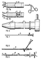
- the set of instruments also consists of known observation optics 14 (FIG. 7) and working optics 15 (FIG. 8) with a continuous channel for instruments to be carried out and an aspiration probe 16 according to FIG. 9, through the shaft of which a puncture needle 17 with a proximal hose connection can be coupled 18 is guided and which can be connected proximally via a switchable connection 19 to a supply and discharge of a rinsing liquid.
- the probe tube 16a is provided with a guide thickening 20 distally.
- the set of instruments further consists of two dilators according to FIGS. 5a, 5b and 6 and of a clip applicator according to FIGS. 2 and 4.
- the first dilator 21 according to FIGS. 5a and 5b consists of two cone halves 23 and 24 connected by a joint 22, which can be expanded by a scissor handle 25.
- the second dilator 26 has a rigid cone 27 and is provided with a continuous channel for an observation optics 14 according to FIG. 7, which can be coupled together with the dilator.
- the clip applicator according to FIGS. 2 to 4 consists of a shaft 28, in the distal end of which the two jaw legs 29 are pivoted by a proximal handle, not shown. In the closed position, the jaw legs 29 are held parallel at a distance by lateral pairs of stops 30 and are provided with teeth 31 facing one another.
- an outer shaft 32 with a distal V-shaped cutout 33 is mounted so as to be longitudinally displaceable, by means of which a deformable clip 34, which is pushed onto the shaft 28 as far as behind the jaw joint, plastically deforms into an application position according to FIG. 2b and finally for closing the dilated gallbladder incision will, as will be explained in more detail.
- the clip 34 is provided with an opening 35 through which the applicator can be pushed with a slightly open mouth in order to reach over the two stops until it has reached a position according to FIG. 2a.
- the clip is further provided with inwardly directed projections 36 which come into contact with the stops 30 of the jaw legs 29 when the clip is advanced distally through the outer shaft 32 into the application position according to FIG. 2b.
- the two clip legs 37 are toothed on the inner sides facing each other.
- the instrument according to FIG. 1 together with the working optics according to FIG. 8 and the aspiration probe according to FIG. 9 is inserted through the abdominal wall into the body cavity, and the gallbladder is then observed by means of the four pliers 8 are gripped and held at four points in the rectangle.
- the gallbladder is then incised through the puncture needle 17 and a certain amount of bile juice is aspirated.
- the gallbladder is rinsed.
- the probe tube 16a is then pulled out of the gallbladder and from the channel of the working optics 15, and the probe is replaced by the first dilator 21 according to FIGS. 5a and 5b, by means of which the incision of the gallbladder made by the puncture needle 17 by means of the one to be spread Dilator cone 23.24 is expanded.
- the dilator 21 and the working optics 15 are replaced by the second dilator 26 with the observation optics 14 through them as shown in FIG. 7, and the incision of the gallbladder is widened further by pulling the gallbladder gripped by the forceps 8 onto the inner tube 2.
- the forceps 8 are rotated about their longitudinal axis in such a way that the folds of the gallbladder that are detected occupy a plane parallel or approximately parallel to the circumference of the dilator.
- the second dilator 26 with the observation optics 14 is removed and replaced by the working optics 15, through which the gallstones are now broken up and / or removed.
- the clip applicator according to FIG. 2a is then passed through the working optics with the mouth closed, which is removed from the tube 1,2, whereupon the clip 34 is pushed distally through the outer shaft 32 into the application position according to FIG. 2b. Subsequently, the outer shaft 32 is to be pushed further distally, so that the legs of the released clip 34 are deformed by the V-shaped incision 33 and capture and compress the bladder tissue by means of the clip teeth, whereby the incision is now properly closed. Finally, after the sliding outer shaft 32 has been pulled back, the clip applicator is opened and pulled out with the working optics, and then the tube 1, 2 is likewise removed from the body cavity.
Description
Die Erfindung geht aus von einem Instrumentensatz zum Verschließen von eröffneten Hohlorganen und Wunden, bestehend aus einem Außentubus und einem unlösbar mit diesem festgelegten Innentubus sowie Kanälen für hindurchzuführende Zangen zum Festhalten des Hohlorgans oder der Wundränder und aus einer durch den Innentubus hindurchzuführenden Arbeitsoptik mit Kanal zur Hindurchführung von Hilfsinstrumenten.The invention is based on a set of instruments for closing opened hollow organs and wounds, consisting of an outer tube and an inner tube permanently attached to this, as well as channels for pliers to be passed through for holding the hollow organ or wound edges, and a working optics with a channel for passing through the inner tube of auxiliary instruments.
Ein solcher Instrumentensatz ist in der DE-PS 35 04 292 beschrieben. Dieser Instrumentensatz zur perkutanen Gallensteinentfernung besteht aus einem festlegbaren Außentubus mit Kanälen für durchzuführende Zangen zum Festhalten der Gallenblase und aus einem Innentubus für eine durchzuführende Arbeitsoptik und zur Hindurchführung von Instrumenten für die Entfernung von Gallensteinen.Such a set of instruments is described in DE-PS 35 04 292. This set of instruments for percutaneous gallstone removal consists of a definable outer tube with channels for pliers to be carried out to hold the gallbladder in place and an inner tube for optics to be performed and for passing instruments for the removal of gallstones.
Durch die Anordnung der Zangenkanäle auf der Trokarhülse als Außentubus ist nur eine ungenügende Reinigung, Desinfektion und Sterilisation möglich, und es besteht keine Möglichkeit, den zu ergreifenden Gewebeteil der Gallenblase einwandfrei sicher zu halten und entsprechend den Anforderungen manipulieren und die verhältnismäßig groß vorzunehmende Inzision der Gallenblase nach der Entfernung der Gallensteine wieder einwandfrei dicht verschließen zu können.Due to the arrangement of the forceps channels on the trocar sleeve as the outer tube, only insufficient cleaning, disinfection and sterilization is possible, and there is no possibility of holding the tissue part of the gallbladder perfectly safe and manipulating it according to the requirements and the relatively large incision of the gallbladder after the gallstones have been removed, they can be properly sealed again.
Des weiteren ist bekannt, Wunden mit Klammern, die mit entsprechenden Klammergeräten appliziert werden, zu verschließen, und es sind auch solche Klammergeräte für den Einsatz bei endoskopischen Eingriffen bekannt. In der DE-OS 37 13 830 ist ein solches Klammergerät für den Wundverschluß mit Klammern beschrieben, das durch den Instrumentenkanal eines Laparoskopes einführbar ist. Bei diesem Klammergerät ist die Biegebewegung wenigstens eines der Biegeglieder längs des Schaftes gerichtet, und die Druckelemente der Biegeglieder sind seitlich zueinander versetzt. Hierdurch wird eine kleine Bauweise diese Klammergerätes erreicht, so daß es bei einem Laparoskop einsetzbar ist.Furthermore, it is known to close wounds with staples, which are applied with appropriate stapling devices, and such stapling devices are also known for use in endoscopic interventions. DE-OS 37 13 830 describes such a stapling device for wound closure with staples, which can be inserted through the instrument channel of a laparoscope. In this stapler, the bending movement of at least one of the bending members is directed along the shaft, and the pressure elements of the bending members are laterally offset from one another. This results in a small construction of this stapler, so that it can be used with a laparoscope.
Die Aufgabe der Erfindung besteht darin, einem Instrumentensatz der einleitend angeführten Art zu verbessern, um unter Vermeidung der genannten Nachteile vor allen Dingen einen sicheren Verschluß von eröffneten Hohlorganen oder Wunden, wie z. B. der inzisierten Gallenblase, zu erreichen, ohne daß ein weiterer Einstich in die Körperhöhle für die Einführung eines entsprechenden Verschließinstrumentes vorgenommen werden muß.The object of the invention is to improve an instrument set of the type mentioned in order to avoid the above-mentioned disadvantages, above all things, a secure closure of opened hollow organs or wounds, such as. B. the incised gallbladder, without having to make another puncture into the body cavity for the introduction of a corresponding closing instrument.
Diese Aufgabe wird durch die Merkmale des Anspruches 1 gelöst. Bevorzugte Ausgestaltungsmerkmale der erfindungsgemäßen Lösung sind in den Unteransprüchen angeführt.This object is solved by the features of claim 1. Preferred design features of the solution according to the invention are set out in the subclaims.
Durch die Lösung nach der Erfindung ist es möglich, das Gewebe des Hohlorganes oder der Wunden nach Einführen des Instrumentes aus Außentubus und Innentubus mit Festhaltezangen unter Beobachtung mittels einer Arbeitsoptik durch die Bauchdecke hindurch in die Körperhöhle an das Hohlorgan heranzuführen und das Gewebe des Hohlorgans an zwei, vorteilhaft an vier sich diagonal gegenüberliegenden Stellen durch die Zangen sicher zu erfassen und festzuhalten. Sodann kann die Inzision mittels einer Aspirationssonde mit Punktionsnadel durchgeführt und die Inzision durch Dilatatoren aufgeweitet und anschließend durch den Clipapplikator verschlossen werden. Durch die Ausbildung des Instrumentensatzes gemäß der Erfindung ist eine einwandfreie Reinigung, Desinfektion und Sterilisation aller seiner Teile möglich. Das sicher erfaßte Gewebe der Gallenblase kann einfach manipuliert, und nach dem Entfernen von Gallen steinen kann der Einschnitt in der Gallenblase mittels der Inzisionsnadel wieder mittels eines Applikators und eines Clips sicher verschlossen werden.With the solution according to the invention it is possible to bring the tissue of the hollow organ or the wounds after insertion of the instrument from the outer tube and inner tube with holding forceps under observation by means of working optics through the abdominal wall into the body cavity to the hollow organ and the tissue of the hollow organ to two , advantageously to be gripped and held securely by the pliers at four diagonally opposite points. The incision can then be made using an aspiration probe with a puncture needle, and the incision can be widened by dilators and then closed by the clip applicator. The design of the set of instruments according to the invention enables flawless cleaning, disinfection and sterilization of all of its parts. The securely grasped tissue of the gallbladder can easily be manipulated, and after gall removal the incision in the gallbladder can be securely closed again using the incision needle using an applicator and a clip.
Die Erfindung ist nachstehend im einzelnen anhand der Zeichnung erläutert. Es zeigen:
- Figur 1 eine Seitenansicht des Außentubus mit Innentubus und Festhaltezangen,
Figur 2a + 2b in Seitenansicht das vergrößerte Ende eines Clipapplikators mit geöffnetem und geschlossenem Maul,- Figur 2c den gleichen Clipapplikator mit distalwärts vorgeschobenem Außenschaft,
- Figur 3 einen Clip, gesehen in Richtung gegen dessen offenes Ende,
- Figur 4 eine Stirnansicht gegen das distale geschlossene Ende des Applikatormaules,
- Figur 5a + 5b einen ersten Dilatator in zwei um 90° versetzten, vergrößerten Seitenansichten,
- Figur 6 die Seitenansicht eines zweiten Dilatators,
- Figur 7 eine Seitenansicht einer üblichen Beobachtungsoptik,
- Figur 8 eine Seitenansicht einer bekannten Arbeitsoptik und
- Figur 9 eine Seitenansicht einer Aspirationssonde mit Punktionsnadel und ankuppelbarem, umschaltbarem Spül- und Sauganschluß.
- FIG. 1 shows a side view of the outer tube with inner tube and holding tongs,
- 2a + 2b in side view the enlarged end of a clip applicator with open and closed mouth,
- 2c shows the same clip applicator with the outer shaft advanced distally,
- FIG. 3 shows a clip, viewed in the direction towards its open end,
- FIG. 4 shows an end view against the distal closed end of the applicator mouth,
- 5a + 5b a first dilator in two enlarged side views offset by 90 °,
- FIG. 6 shows the side view of a second dilator,
- FIG. 7 shows a side view of a conventional observation optics,
- Figure 8 is a side view of a known work optics and
- FIG. 9 shows a side view of an aspiration probe with a puncture needle and a connectable, switchable rinsing and suction connection.
Der dargestellte Instrumentensatz besteht nach Figur 1 aus einem Außentubus 1 mit darin unlösbar festgelegtem Innentubus 2, der distale Öffnungen 2a zur Kontrolle der korrekten Lage des über den Innentubus 2 zu ziehenden Gewebes aufweist, distal gegenüber dem Außentubus vorspringt und der einen proximal durch eine Dichtung 3 abgedichteten Kanal 4 aufweist. Durch einen verschließbaren Anschlußstutzen 5 besteht die Möglichkeit über den Kanal 4 in eine Körperhöhle Gas oder eine Spülflüssigkeit einzuführen und letztere mit etwaigen Sekreten oder dergleichen abzusaugen. Der Außentubus 1 ist proximal mit einer Handhabe 6 versehen, deren starre Verlängerung 7 an einer feststehenden Vorrichtung, z. B. mittels eines verriegelbaren Gelenkarmes oder dergleichen an einem Operationstisch, befestigt werden kann, um den Tubus bzw. das gesamte Instrument für den Eingriff ortsfest halten zu können.According to FIG. 1, the instrument set shown consists of an outer tube 1 with an inner tube 2, which is fixed therein inseparably, which has
Zwischen Außen- und Innentubus verlaufen zwei, vorteilhaft vier sich im Rechteck diagonal gegenüberliegende Kanäle, durch die halbstarr ausgebildete Zangen 8 zum Festhalten der Gallenblase verlaufen, deren vorzugsweise beide hakenförmig ausgebildete, in einer Nut geführte Maulschenkel 9 durch proximale, federvorgespannte Handgriffteile 10 und 11 betätigbar sind. Die Zangen 8 durchlaufen proximale Dichtungen 12 der Kanäle 13 und verlaufen an ihren distalen und den proximalen Enden im Winkel zur Längsachse des Tubus 1 nach außen, um einerseits das Gewebe bezüglich seiner Lage relative zum Maulteil des Applikators manipulieren zu können und um andererseits die Handhabung zu erleichtern.Between the outer and inner tubes run two, advantageously four, diagonally opposite channels in the rectangle, through which semi-rigid pliers 8 run to hold the gallbladder, the preferably both hook-shaped jaws 9 guided in a groove can be actuated by proximal, spring-
Der Instrumentensatz besteht weiter aus einer bekannten Beobachtungsoptik 14 (Fig. 7) und einer Arbeitsoptik 15 (Fig. 8) mit durchlaufendem Kanal für durchzuführende Instrumente und weiter aus einer Aspirationssonde 16 nach Fig. 9, durch deren Schaft eine ankuppelbare Punktionsnadel 17 mit proximalem Schlauchanschluß 18 geführt ist und die proximal über einen umschaltbaren Anschluß 19 an eine Zufuhr und Abfuhr einer Spülflüssigkeit anschließbar ist.The set of instruments also consists of known observation optics 14 (FIG. 7) and working optics 15 (FIG. 8) with a continuous channel for instruments to be carried out and an
Das Sondenrohr 16a ist distal mit einer Führungsverdickung 20 versehen.The probe tube 16a is provided with a guide thickening 20 distally.
Der Instrumentensatz besteht weiter aus zwei Dilatatoren gemäß den Figuren 5a, 5b und 6 und aus einem Clipapplikator nach den Figuren 2 und 4.The set of instruments further consists of two dilators according to FIGS. 5a, 5b and 6 and of a clip applicator according to FIGS. 2 and 4.
Der erste Dilatator 21 nach Fig. 5a und 5b besteht aus zwei durch ein Gelenk 22 verbundenen Kegelhälften 23 und 24, die durch einen Scherengriff 25 spreizbar sind. Der zweite Dilatator 26 weist einen starren Kegel 27 auf und ist mit einem durchlaufenden Kanal für eine Beobachtungsoptik 14 nach Fig. 7 versehen, die mit dem Dilatator zusammengekuppelt werden kann.The
Der Clipapplikator nach Figur 2 bis 4 besteht aus einem Schaft 28, in dessen distalem Ende die beiden Maulschenkel 29 durch eine proximale, nicht dargestellte Handhabe verschwenkt werden. Die Maulschenkel 29 werden in der Schließlage parallel im Abstand durch seitliche Anschlagpaare 30 gehalten und sind mit zueinandergekehrten Zähnen 31 versehen. Auf dem Schaft 28 ist ein Außenschaft 32 mit distalem V-förmigen Ausschnitt 33 längsverschiebbar gelagert, durch die ein deformierbarer, auf dem Schaft 28 bis hinter das Maulgelenk aufgeschobener Clip 34 in eine Applikationsstellung nach Fig. 2b und schließlich zum Schließen des dilatierten Gallenblaseneinschnittes plastisch verform wird, wie noch näher erläutert wird.The clip applicator according to FIGS. 2 to 4 consists of a
Der Clip 34 ist mit einer Durchbrechung 35 versehen, durch den der Applikator zum Übergreifen der beiden Anschläge mit leicht geöffnetem Maul hindurchschiebbar ist, bis er eine Lage nach Fig. 2a erreicht hat. Der Clip ist weiter mit nach innen gerichteten Vorsprüngen 36 versehen, die beim distalwärtigen Vorschub des Clips durch den Außenschaft 32 in die Applikationsstellung nach Fig. 2b gegen die Anschläge 30 der Maulschenkel 29 zur Anlage kommen. Die beiden Clipschenkel 37 sind auf den einander zugekehrten Innenseiten verzahnt.The
Die Arbeitsweise des vorbeschriebenen Instrumentensatzes nach der Erfindung ist folgende.The operation of the above-described set of instruments according to the invention is as follows.
Durch die Bauchdecke wird das Instrument nach Figur 1 zusammen mit der Arbeitsoptik nach Fig. 8 und der Aspirationssonde nach Fig. 9 in die Körperhöhle eingeführt, und es wird dann die Gallenblase unter Beobachtung mittels der vier Zangen 8 an vier im Rechteck liegenden Stellen erfaßt und festgehalten. Sodann wird die Gallenblase durch die Punktionsnadel 17 inzisiert und eine bestimmte Menge Gallensaft abgesaugt. Nach dem vollständigen Einführen des distalen Sondenendes 20 des Spül- und Saugrohres 16a in die Gallenblase und nach Entfernen der Punktionsnadel 17 erfolgt ein Spülen der Gallenblase.The instrument according to FIG. 1 together with the working optics according to FIG. 8 and the aspiration probe according to FIG. 9 is inserted through the abdominal wall into the body cavity, and the gallbladder is then observed by means of the four pliers 8 are gripped and held at four points in the rectangle. The gallbladder is then incised through the
Anschließend erfolgt das Herausziehen des Sondenrohres 16a aus der Gallenblase und aus dem Kanal der Arbeitsoptik 15, und die Sonde wird durch den ersten Dilatator 21 nach Fig. 5a und 5b ersetzt, durch die die durch die Punktionsnadel 17 erfolgte Inzision der Gallenblase mittels des zu spreizenden Dilatatorkegels 23,24 aufgeweitet wird. Anschließend wird der Dilatator 21 und die Arbeitsoptik 15 durch den zweiten Dilatator 26 mit der durch ihn hindurchgeführten Beobachtungsoptik 14 nach Fig. 7 ersetzt und die Inzision der Gallenblase weiter aufgeweitet, indem die durch die Zangen 8 erfaßte Gallenblase auf den Innentubus 2 aufgezogen wird. Die Zangen 8 sind dabei so um ihre Längsachse verdreht, daß die erfaßten Falten der Gallenblase eine Ebene parallel oder etwa parallel zum Umfang des Dilatators einnehmen.The probe tube 16a is then pulled out of the gallbladder and from the channel of the
Im Anschluß daran wird der zweite Dilatator 26 mit der Beobachtungsoptik 14 entfernt und durch die Arbeitsoptik 15 ersetzt, durch die hindurch nunmehr die Zertrümmerung und/oder Entfernung von Gallensteinen erfolgt.Subsequently, the
Es wird anschließend der Clipapplikator nach Fig. 2a durch die aus dem Tubus 1,2 herausgenommene Arbeitsoptik mit geschlossenem Maul hindurchgeführt, worauf der Clip 34 durch den Außenschaft 32 in die Applikationsstellung nach Fig. 2b distalwärts geschoben wird. Anschließend ist der Außenschaft 32 weiter distalwärts zu schieben, so daß nunmehr die Schenkel des freigewordenen Clips 34 durch den V-förmigen Einschnitt 33 deformierend das Blasengewebe mittels der Clipverzahnung erfassen und zusammendrücken, wodurch nunmehr die Inzision einwandfrei verschlossen ist. Schließlich wird der Clipapplikator nach Zurückziehen des verschiebbaren Außenschftes 32 geöffnet und mit der Arbeitsoptik herausgezogen, und sodann wird der Tubus 1, 2 ebenfalls aus der Körperhöhle entfernt.The clip applicator according to FIG. 2a is then passed through the working optics with the mouth closed, which is removed from the tube 1,2, whereupon the
Claims (12)
- A set of instruments for the closing of opened hollow organs and wounds, consisting of an outer tube (1) and of an inner tube (2), fixed undetachably therewith, and also of channels (13) for forceps, which are to be passed therethrough, to secure the hollow organ or the edges of the wound, and of a working optical system (14), to be passed through the inner tube (2), with a channel for the passage through of auxiliary instruments and the like, characterised in that at least two channels (13) for holding forceps (8) run between the outer tube (1) and the inner tube (2), projecting distally beyond the outer tube, that an observation optical system (14), insertable through the inner tube (2), and an aspiration probe (16) with removable puncture needle (17) are provided, that dilators (21, 26) for widening an incision in a hollow organ or the wound are exchangeable for the probe (16) and that the observation optical system (14) is provided so as to be exchangeable for the working optical system (15), which can be releasably secured in the inner tube (2) and is provided with a clip applicator (28-33) with a clip (34), which can be pushed thereon distally and is releasable in a distal direction, to close an opened hollow organ or a wound.
- A set of instruments according to claim 1, characterised in that the channels (13) running between the outer- and inner tube (1,2) are bent proximally outwards and have a seal (12) for the holding forceps (8), which are actuable proximally and are made semi-rigid, the two distal jaw piece grips (9) of which, guided in each case in a groove, are constructed in a hooked shape.
- A set of instruments according to claim 1 or 2, characterised in that a plane, which extends transversely to the plane of the jaw (9) of the holding forceps (8), forms an angle with the longitudinal axis of the forceps.
- A set of instruments according to one of claims 1 to 3, characterised in that the channel formed by the inner tube (2) is sealed proximally by a seal (3) and is provided with a closable tap (5) for the supply and removal of flushing fluid or gas from body cavities.
- A set of instruments according to one of claims 1 to 4, characterised in that the outer tube (1) is provided with a handle (6), the rigid extension (7) of which is securable.
- A set of instruments according to one of claims 1 to 5, characterised in that a first dilator (21) for widening the incision which has been made by means of the puncture needle (17) comprises a cone (23,24) divided in the axial direction, the articulatedly connected halves of which are spreadable by a proximal handle (25).
- A set of instruments according to claim 6, characterised in that the two cone halves (23, 24) are provided on both sides with depressions (24a) situated opposite each other, into which the borders of the wound of the opened organ or the wound edges of the wound engage.
- A set of instruments according to claims 1 to 5, characterised in that in addition to the dilator (21) according to claim 6 or 7, a second dilator (26) is provided, having a rigid cone (27) and a central channel to pass through the observation optical system (14), which can be coupled with the proximal end of the dilator (26).
- A set of instruments according to claim 1 and one of claims 2 to 8, characterised in that the aspiration probe (16) comprises a puncture needle (17) which can be coupled proximally with a flushing- and suction tube (16a) and is connectable proximally with a reversible hose connection (19) and that the suction tube (16a) has a widening (20) of the tube at the distal end.
- A set of instruments according to claim 1 and one of claims 2 to 9, characterised in that the clip applicator (28 to 33) has a jaw (29 to 31) which is closable by a proximal handle, the jaw shanks (29) of which are provided with mutually opposed gripper teeth (31), and in each case with pairs of stops (30) on both sides, to rest the two projections (36) of the clip (34) and that on the proximal side of the forceps jaw a plastically deformable clip (34), which is guided in two opposing grooves having a depth decreasing in the proximal direction, is slidable and releasably securable, which clip is deformable by an outer shaft (32), slidable on the applicator, to close the opened hollow organ or the wound, and is able to be releasable thereafter by the applicator after the two jaw shanks (29) have been opened.
- A set of instruments according to claim 10, characterised in that the clip (34), which is penetrable by the applicator (28 to 33), has a recess (35) which is provided with two opposing projections (36), which are brought to rest against the pairs of stops (30) of the jaw shanks (29) by displacing the clip by means of the outer shaft (32).
- A set of instruments according to claim 10 or 11, characterised in that the outer shaft (23), which is displaceable longitudinally on the applicator (28 to 33), is provided distally on both sides with a V-shaped cut-out (33).
Applications Claiming Priority (2)
| Application Number | Priority Date | Filing Date | Title |
|---|---|---|---|
| DE3941108A DE3941108C1 (en) | 1989-12-13 | 1989-12-13 | |
| DE3941108 | 1989-12-13 |
Publications (3)
| Publication Number | Publication Date |
|---|---|
| EP0432560A2 EP0432560A2 (en) | 1991-06-19 |
| EP0432560A3 EP0432560A3 (en) | 1991-08-14 |
| EP0432560B1 true EP0432560B1 (en) | 1993-03-10 |
Family
ID=6395358
Family Applications (1)
| Application Number | Title | Priority Date | Filing Date |
|---|---|---|---|
| EP90122580A Expired - Lifetime EP0432560B1 (en) | 1989-12-13 | 1990-11-27 | Set of instruments to close hollow organs and wounds |
Country Status (3)
| Country | Link |
|---|---|
| US (1) | US5099827A (en) |
| EP (1) | EP0432560B1 (en) |
| DE (2) | DE3941108C1 (en) |
Cited By (3)
| Publication number | Priority date | Publication date | Assignee | Title |
|---|---|---|---|---|
| US6334843B1 (en) | 1995-09-20 | 2002-01-01 | Medtronic, Inc. | Method and apparatus for temporarily immobilizing a local area of tissue |
| US6464629B1 (en) | 1998-09-15 | 2002-10-15 | Medtronic, Inc. | Method and apparatus for temporarily immobilizing a local area of tissue |
| US6565582B2 (en) | 1995-02-24 | 2003-05-20 | Hearport, Inc. | Devices and methods for performing a vascular anastomosis |
Families Citing this family (96)
| Publication number | Priority date | Publication date | Assignee | Title |
|---|---|---|---|---|
| US5797939A (en) * | 1989-12-05 | 1998-08-25 | Yoon; Inbae | Endoscopic scissors with longitudinal operating channel |
| US5984939A (en) * | 1989-12-05 | 1999-11-16 | Yoon; Inbae | Multifunctional grasping instrument with cutting member and operating channel for use in endoscopic and non-endoscopic procedures |
| US5665100A (en) * | 1989-12-05 | 1997-09-09 | Yoon; Inbae | Multifunctional instrument with interchangeable operating units for performing endoscopic procedures |
| US5797958A (en) * | 1989-12-05 | 1998-08-25 | Yoon; Inbae | Endoscopic grasping instrument with scissors |
| DE4131495C1 (en) * | 1991-09-21 | 1993-04-29 | Harald 5000 Koeln De Heidmueller | |
| US5290299A (en) * | 1991-12-11 | 1994-03-01 | Ventritex, Inc. | Double jaw apparatus for attaching implanted materials to body tissue |
| US5269772A (en) * | 1992-01-24 | 1993-12-14 | Wilk Peter J | Laparoscopic cannula assembly and associated method |
| US5575751A (en) * | 1992-05-14 | 1996-11-19 | The United States Of America As Represented By The Department Of Health And Human Services | Device for measuring incident light in a body cavity |
| US5505687A (en) * | 1992-05-14 | 1996-04-09 | The United States Of America As Represented By The Department Of Health And Human Services | Device for measuring incident light in a body cavity |
| US5318013A (en) * | 1992-11-06 | 1994-06-07 | Wilk Peter J | Surgical clamping assembly and associated method |
| US5312391A (en) * | 1992-07-29 | 1994-05-17 | Wilk Peter J | Laparoscopic instrument assembly |
| US5395367A (en) * | 1992-07-29 | 1995-03-07 | Wilk; Peter J. | Laparoscopic instrument with bendable shaft and removable actuator |
| US5511564A (en) * | 1992-07-29 | 1996-04-30 | Valleylab Inc. | Laparoscopic stretching instrument and associated method |
| US5376087A (en) * | 1992-08-21 | 1994-12-27 | Habley Medical Technology Corporation | Multiple function cauterizing instrument |
| US5485952A (en) * | 1992-09-23 | 1996-01-23 | United States Surgical Corporation | Apparatus for applying surgical fasteners |
| US5735792A (en) * | 1992-11-25 | 1998-04-07 | Clarus Medical Systems, Inc. | Surgical instrument including viewing optics and an atraumatic probe |
| US5403326A (en) * | 1993-02-01 | 1995-04-04 | The Regents Of The University Of California | Method for performing a gastric wrap of the esophagus for use in the treatment of esophageal reflux |
| ATE153231T1 (en) * | 1993-04-27 | 1997-06-15 | American Cyanamid Co | AUTOMATIC LAPAROSCOPIC APPLICATOR FOR LIVING CLIPS |
| US5578031A (en) * | 1993-05-10 | 1996-11-26 | Wilk; Peter J. | Laparoscopic instrument assembly and associated method |
| DE4404781B4 (en) * | 1994-02-09 | 2005-03-24 | Aesculap Ag & Co. Kg | Medical device for injecting and / or aspirating liquids into or out of a hollow organ, in particular a bile duct |
| DE4404253A1 (en) * | 1994-02-10 | 1995-08-17 | Univ Ludwigs Albert | Examination and surgical accessory for body cavities |
| WO1995033407A1 (en) * | 1994-06-06 | 1995-12-14 | Valleylab Inc. | Surgical spreader assembly and associated method |
| US5571116A (en) * | 1994-10-02 | 1996-11-05 | United States Surgical Corporation | Non-invasive treatment of gastroesophageal reflux disease |
| US5716321A (en) * | 1995-10-10 | 1998-02-10 | Conceptus, Inc. | Method for maintaining separation between a falloposcope and a tubal wall |
| US6004341A (en) * | 1996-12-05 | 1999-12-21 | Loma Linda University Medical Center | Vascular wound closure device |
| JPH09173341A (en) * | 1995-12-25 | 1997-07-08 | Olympus Optical Co Ltd | Clamping forceps |
| DE19627992A1 (en) * | 1996-07-11 | 1998-01-22 | Storz Karl Gmbh & Co | Instrument with two independent jaws |
| WO1998007375A1 (en) | 1996-08-22 | 1998-02-26 | The Trustees Of Columbia University | Endovascular flexible stapling device |
| US7416554B2 (en) * | 2002-12-11 | 2008-08-26 | Usgi Medical Inc | Apparatus and methods for forming and securing gastrointestinal tissue folds |
| US7637905B2 (en) * | 2003-01-15 | 2009-12-29 | Usgi Medical, Inc. | Endoluminal tool deployment system |
| US8574243B2 (en) | 1999-06-25 | 2013-11-05 | Usgi Medical, Inc. | Apparatus and methods for forming and securing gastrointestinal tissue folds |
| US6911032B2 (en) | 1999-11-18 | 2005-06-28 | Scimed Life Systems, Inc. | Apparatus and method for compressing body tissue |
| US6428548B1 (en) | 1999-11-18 | 2002-08-06 | Russell F. Durgin | Apparatus and method for compressing body tissue |
| US8241274B2 (en) | 2000-01-19 | 2012-08-14 | Medtronic, Inc. | Method for guiding a medical device |
| US6716226B2 (en) * | 2001-06-25 | 2004-04-06 | Inscope Development, Llc | Surgical clip |
| US7232445B2 (en) * | 2000-12-06 | 2007-06-19 | Id, Llc | Apparatus for the endoluminal treatment of gastroesophageal reflux disease (GERD) |
| US8062314B2 (en) * | 2000-12-06 | 2011-11-22 | Ethicon Endo-Surgery, Inc. | Methods for the endoluminal treatment of gastroesophageal reflux disease (GERD) |
| US20020068945A1 (en) * | 2000-12-06 | 2002-06-06 | Robert Sixto | Surgical clips particularly useful in the endoluminal treatment of gastroesophageal reflux disease (GERD) |
| US7727246B2 (en) * | 2000-12-06 | 2010-06-01 | Ethicon Endo-Surgery, Inc. | Methods for endoluminal treatment |
| US20020138086A1 (en) * | 2000-12-06 | 2002-09-26 | Robert Sixto | Surgical clips particularly useful in the endoluminal treatment of gastroesophageal reflux disease (GERD) |
| US6808491B2 (en) | 2001-05-21 | 2004-10-26 | Syntheon, Llc | Methods and apparatus for on-endoscope instruments having end effectors and combinations of on-endoscope and through-endoscope instruments |
| EP1434529B1 (en) * | 2001-10-01 | 2009-09-23 | The Cleveland Clinic Foundation | Skin lesion exciser and skin-closure device therefor |
| US7513902B2 (en) * | 2001-10-01 | 2009-04-07 | The Cleveland Clinic Foundation | Skin lesion exciser and skin-closure device therefor |
| US7094245B2 (en) * | 2001-10-05 | 2006-08-22 | Scimed Life Systems, Inc. | Device and method for through the scope endoscopic hemostatic clipping |
| US7494460B2 (en) | 2002-08-21 | 2009-02-24 | Medtronic, Inc. | Methods and apparatus providing suction-assisted tissue engagement through a minimally invasive incision |
| WO2004023976A2 (en) * | 2002-09-13 | 2004-03-25 | Damage Control Surgical Technologies, Inc. | Method and apparatus for vascular and visceral clipping |
| US7186251B2 (en) | 2003-03-27 | 2007-03-06 | Cierra, Inc. | Energy based devices and methods for treatment of patent foramen ovale |
| US7972330B2 (en) | 2003-03-27 | 2011-07-05 | Terumo Kabushiki Kaisha | Methods and apparatus for closing a layered tissue defect |
| US8021362B2 (en) * | 2003-03-27 | 2011-09-20 | Terumo Kabushiki Kaisha | Methods and apparatus for closing a layered tissue defect |
| US7165552B2 (en) * | 2003-03-27 | 2007-01-23 | Cierra, Inc. | Methods and apparatus for treatment of patent foramen ovale |
| US7293562B2 (en) * | 2003-03-27 | 2007-11-13 | Cierra, Inc. | Energy based devices and methods for treatment of anatomic tissue defects |
| US6939348B2 (en) | 2003-03-27 | 2005-09-06 | Cierra, Inc. | Energy based devices and methods for treatment of patent foramen ovale |
| WO2004087235A2 (en) * | 2003-03-27 | 2004-10-14 | Cierra, Inc. | Methods and apparatus for treatment of patent foramen ovale |
| US7311701B2 (en) * | 2003-06-10 | 2007-12-25 | Cierra, Inc. | Methods and apparatus for non-invasively treating atrial fibrillation using high intensity focused ultrasound |
| JP4266738B2 (en) | 2003-07-02 | 2009-05-20 | オリンパス株式会社 | Ligation device |
| US7799042B2 (en) * | 2004-05-13 | 2010-09-21 | The Cleveland Clinic Foundation | Skin lesion exciser and skin-closure device therefor |
| US7367975B2 (en) | 2004-06-21 | 2008-05-06 | Cierra, Inc. | Energy based devices and methods for treatment of anatomic tissue defects |
| CA2599310C (en) * | 2005-04-11 | 2013-12-10 | Cierra, Inc. | Methods and apparatus to achieve a closure of a layered tissue defect |
| US8518024B2 (en) * | 2006-04-24 | 2013-08-27 | Transenterix, Inc. | System and method for multi-instrument surgical access using a single access port |
| CA2650474A1 (en) | 2006-04-24 | 2007-11-08 | Synecor, Llc | Natural orifice surgical system |
| US7794387B2 (en) | 2006-04-26 | 2010-09-14 | Medtronic, Inc. | Methods and devices for stabilizing tissue |
| US7927271B2 (en) * | 2006-05-17 | 2011-04-19 | C.R. Bard, Inc. | Endoscope tool coupling |
| US20080140069A1 (en) * | 2006-12-07 | 2008-06-12 | Cierra, Inc. | Multi-electrode apparatus for tissue welding and ablation |
| US7655004B2 (en) | 2007-02-15 | 2010-02-02 | Ethicon Endo-Surgery, Inc. | Electroporation ablation apparatus, system, and method |
| US20110060183A1 (en) * | 2007-09-12 | 2011-03-10 | Salvatore Castro | Multi-instrument access devices and systems |
| US20090227843A1 (en) * | 2007-09-12 | 2009-09-10 | Smith Jeffrey A | Multi-instrument access devices and systems |
| US20090105816A1 (en) * | 2007-10-19 | 2009-04-23 | Olsen Daniel H | System using a helical retainer in the direct plication annuloplasty treatment of mitral valve regurgitation |
| US8197464B2 (en) * | 2007-10-19 | 2012-06-12 | Cordis Corporation | Deflecting guide catheter for use in a minimally invasive medical procedure for the treatment of mitral valve regurgitation |
| JP5421987B2 (en) * | 2008-04-23 | 2014-02-19 | クック メディカル テクノロジーズ エルエルシー | Mounting device |
| US8888792B2 (en) * | 2008-07-14 | 2014-11-18 | Ethicon Endo-Surgery, Inc. | Tissue apposition clip application devices and methods |
| AU2009282596A1 (en) * | 2008-08-19 | 2010-02-25 | Wilson-Cook Medical Inc. | Apparatus for removing lymph nodes or anchoring into tissue during a translumenal procedure |
| EP2328482B1 (en) * | 2008-08-29 | 2012-09-26 | Cook Medical Technologies LLC | Stapling device for closing perforations |
| US8192461B2 (en) * | 2008-09-11 | 2012-06-05 | Cook Medical Technologies Llc | Methods for facilitating closure of a bodily opening using one or more tacking devices |
| US20100069924A1 (en) * | 2008-09-11 | 2010-03-18 | Wilson-Cook Medical Inc. | Methods for achieving serosa-to-serosa closure of a bodily opening using one or more tacking devices |
| US8157834B2 (en) | 2008-11-25 | 2012-04-17 | Ethicon Endo-Surgery, Inc. | Rotational coupling device for surgical instrument with flexible actuators |
| JP2012511403A (en) * | 2008-12-09 | 2012-05-24 | クック メディカル テクノロジーズ エルエルシー | Apparatus and method for controlled release of anchoring devices |
| EP2373230B1 (en) | 2008-12-09 | 2012-11-28 | Cook Medical Technologies LLC | Retractable tacking device |
| JP5565881B2 (en) * | 2008-12-19 | 2014-08-06 | クック メディカル テクノロジーズ エルエルシー | Clip device and delivery and deployment method |
| US20100160931A1 (en) * | 2008-12-19 | 2010-06-24 | Wilson-Cook Medical Inc. | Variable thickness tacking devices and methods of delivery and deployment |
| US20110230723A1 (en) * | 2008-12-29 | 2011-09-22 | Salvatore Castro | Active Instrument Port System for Minimally-Invasive Surgical Procedures |
| WO2010138579A1 (en) * | 2009-05-28 | 2010-12-02 | Wilson-Cook Medical Inc. | Tacking device and methods of deployment |
| AU2010278901A1 (en) * | 2009-07-29 | 2012-03-15 | Transenterix, Inc. | Deflectable instrument ports |
| US20110098704A1 (en) | 2009-10-28 | 2011-04-28 | Ethicon Endo-Surgery, Inc. | Electrical ablation devices |
| US9233241B2 (en) | 2011-02-28 | 2016-01-12 | Ethicon Endo-Surgery, Inc. | Electrical ablation devices and methods |
| US9254169B2 (en) | 2011-02-28 | 2016-02-09 | Ethicon Endo-Surgery, Inc. | Electrical ablation devices and methods |
| US9265514B2 (en) | 2012-04-17 | 2016-02-23 | Miteas Ltd. | Manipulator for grasping tissue |
| US9427255B2 (en) | 2012-05-14 | 2016-08-30 | Ethicon Endo-Surgery, Inc. | Apparatus for introducing a steerable camera assembly into a patient |
| US9545290B2 (en) | 2012-07-30 | 2017-01-17 | Ethicon Endo-Surgery, Inc. | Needle probe guide |
| US10314649B2 (en) | 2012-08-02 | 2019-06-11 | Ethicon Endo-Surgery, Inc. | Flexible expandable electrode and method of intraluminal delivery of pulsed power |
| US9277957B2 (en) | 2012-08-15 | 2016-03-08 | Ethicon Endo-Surgery, Inc. | Electrosurgical devices and methods |
| US10098527B2 (en) | 2013-02-27 | 2018-10-16 | Ethidcon Endo-Surgery, Inc. | System for performing a minimally invasive surgical procedure |
| USD768296S1 (en) * | 2015-09-10 | 2016-10-04 | 7D Surgical, Inc. | Surgical reference clamp |
| HK1210569A2 (en) * | 2015-12-17 | 2016-04-22 | 太津治有限公司 | Surgical device |
| DE102015122497A1 (en) | 2015-12-22 | 2017-06-22 | Karl Storz Gmbh & Co. Kg | Clip applicator |
| DE102015122499A1 (en) | 2015-12-22 | 2017-06-22 | Karl Storz Gmbh & Co. Kg | Medical instrument |
| CN112603424B (en) * | 2020-12-18 | 2022-02-18 | 常州安康医疗器械有限公司 | Tubular anastomat with safety mechanism |
Family Cites Families (12)
| Publication number | Priority date | Publication date | Assignee | Title |
|---|---|---|---|---|
| US4027510A (en) * | 1974-05-15 | 1977-06-07 | Siegfried Hiltebrandt | Forceps |
| JPS5933388B2 (en) * | 1976-03-19 | 1984-08-15 | 高美 上原 | Single-operable biopsy fiberscope |
| GB2130889B (en) * | 1982-11-26 | 1986-06-18 | Wolf Gmbh Richard | Rectoscope |
| US4944443A (en) * | 1988-04-22 | 1990-07-31 | Innovative Surgical Devices, Inc. | Surgical suturing instrument and method |
| DE3344934A1 (en) * | 1983-12-13 | 1985-06-20 | Richard Wolf Gmbh, 7134 Knittlingen | ENDOSCOPE WITH DISTALLY DEFLECTABLE AUXILIARY INSTRUMENT |
| GB2161389B (en) * | 1984-07-05 | 1988-06-08 | Wolf Gmbh Richard | Instrument insert for a uretero-renoscope |
| DE3504252A1 (en) * | 1985-02-08 | 1986-08-14 | Richard Wolf Gmbh, 7134 Knittlingen | URETERO RENOSCOPE |
| DE3504292C1 (en) * | 1985-02-08 | 1986-07-24 | Richard Wolf Gmbh, 7134 Knittlingen | Instrument for endoscopic interventions, especially for percutaneous gallstone removal or gallbladder surgery |
| US4909789A (en) * | 1986-03-28 | 1990-03-20 | Olympus Optical Co., Ltd. | Observation assisting forceps |
| DE3713830C2 (en) * | 1987-04-24 | 1996-02-15 | Frimberger Erintrud | Stapler for wound closure with staples |
| GB2214428B (en) * | 1988-01-09 | 1991-06-26 | Ali Waqar Majeed | Surgical device |
| DE3936811A1 (en) * | 1989-03-25 | 1990-09-27 | Storz Karl | Endoscope for removal of gall stones - has dilator formed from several telescopic tubes |
-
1989
- 1989-12-13 DE DE3941108A patent/DE3941108C1/de not_active Expired - Lifetime
-
1990
- 1990-11-27 DE DE9090122580T patent/DE59001011D1/en not_active Expired - Fee Related
- 1990-11-27 EP EP90122580A patent/EP0432560B1/en not_active Expired - Lifetime
- 1990-12-03 US US07/621,505 patent/US5099827A/en not_active Expired - Fee Related
Cited By (8)
| Publication number | Priority date | Publication date | Assignee | Title |
|---|---|---|---|---|
| US6565582B2 (en) | 1995-02-24 | 2003-05-20 | Hearport, Inc. | Devices and methods for performing a vascular anastomosis |
| US6699257B2 (en) | 1995-02-24 | 2004-03-02 | Heartport, Inc | Devices and methods for performing a vascular anastomosis |
| US6334843B1 (en) | 1995-09-20 | 2002-01-01 | Medtronic, Inc. | Method and apparatus for temporarily immobilizing a local area of tissue |
| US6336898B1 (en) | 1995-09-20 | 2002-01-08 | Medtronic, Inc. | Method and apparatus for temporarily immobilizing a local area of tissue |
| US6364826B1 (en) | 1995-09-20 | 2002-04-02 | Medtronic, Inc. | Method and apparatus for temporarily immobilizing a local area of tissue |
| US6394948B1 (en) | 1995-09-20 | 2002-05-28 | Medtronic, Inc. | Method and apparatus for temporarily immobilizing a local area of tissue |
| US6464630B1 (en) | 1995-09-20 | 2002-10-15 | Medtronic, Inc. | Method and apparatus for temporarily immobilizing a local area of tissue |
| US6464629B1 (en) | 1998-09-15 | 2002-10-15 | Medtronic, Inc. | Method and apparatus for temporarily immobilizing a local area of tissue |
Also Published As
| Publication number | Publication date |
|---|---|
| DE3941108C1 (en) | 1991-06-27 |
| US5099827A (en) | 1992-03-31 |
| DE59001011D1 (en) | 1993-04-15 |
| EP0432560A3 (en) | 1991-08-14 |
| EP0432560A2 (en) | 1991-06-19 |
Similar Documents
| Publication | Publication Date | Title |
|---|---|---|
| EP0432560B1 (en) | Set of instruments to close hollow organs and wounds | |
| EP2185061B1 (en) | Trocar tube, trocar, obturator, or rectoscope for transluminal endoscopic surgery via natural body cavities | |
| EP0659060B1 (en) | Clip for surgical use and clip applicator | |
| EP0412282B1 (en) | Endoscope for nasal surgery | |
| DE4321110C2 (en) | Surgical suction / irrigation instrument | |
| DE3504292C1 (en) | Instrument for endoscopic interventions, especially for percutaneous gallstone removal or gallbladder surgery | |
| DE10126062A1 (en) | Hood for endoscope has flexible tube into which endoscopic treatment instrument can be inserted with opening at distal end for connecting to hollow chamber of cap part | |
| EP0323528B1 (en) | Surgical forceps | |
| AT505002B1 (en) | DEVICE FOR USE IN THE TREATMENT OF A HEMORRHOIDENEPROLAP | |
| EP0742695B1 (en) | Microsurgery instrument | |
| DE202009017988U1 (en) | Surgical instrument | |
| EP1601293B1 (en) | Medical equipment for creating a surgical space for oral surgery | |
| EP1269925A1 (en) | Access cannula for endoscopic surgery, especially for arthroscopy | |
| EP0871403B1 (en) | Device for carrying out manipulations in the human body, in particular in the uterus | |
| EP0626824B1 (en) | Device for transanal resectate extraction | |
| AT402683B (en) | DEVICE FOR ENDOSCOPIC OR LAPAROSCOPIC APPLICATION OF SURGICAL MATERIAL | |
| DE19707361C2 (en) | Extraction bag holder | |
| DE19937043C2 (en) | Medical instrument for creating a cavity for an endoscopic procedure | |
| DE4238596C2 (en) | Mountains device | |
| DE19756629C2 (en) | Instrument, especially trocar or endoscope | |
| EP3409221B1 (en) | Instrument system for minimally invasive surgery in the tissue of a patient | |
| DE4216874C1 (en) | ||
| EP2915492B1 (en) | Instrument for performing surgical sutures in minimally invasive surgery and needle holder coupling for such an instrument | |
| DE102019107434A1 (en) | Surgical shaft instrument with suction device | |
| DE19835235A1 (en) | Dual applicator |
Legal Events
| Date | Code | Title | Description |
|---|---|---|---|
| PUAI | Public reference made under article 153(3) epc to a published international application that has entered the european phase |
Free format text: ORIGINAL CODE: 0009012 |
|
| AK | Designated contracting states |
Kind code of ref document: A2 Designated state(s): BE DE FR GB NL |
|
| PUAL | Search report despatched |
Free format text: ORIGINAL CODE: 0009013 |
|
| AK | Designated contracting states |
Kind code of ref document: A3 Designated state(s): BE DE FR GB NL |
|
| 17P | Request for examination filed |
Effective date: 19920118 |
|
| 17Q | First examination report despatched |
Effective date: 19920716 |
|
| GRAA | (expected) grant |
Free format text: ORIGINAL CODE: 0009210 |
|
| AK | Designated contracting states |
Kind code of ref document: B1 Designated state(s): BE DE FR GB NL |
|
| REF | Corresponds to: |
Ref document number: 59001011 Country of ref document: DE Date of ref document: 19930415 |
|
| GBT | Gb: translation of ep patent filed (gb section 77(6)(a)/1977) |
Effective date: 19930616 |
|
| ET | Fr: translation filed | ||
| PLBE | No opposition filed within time limit |
Free format text: ORIGINAL CODE: 0009261 |
|
| STAA | Information on the status of an ep patent application or granted ep patent |
Free format text: STATUS: NO OPPOSITION FILED WITHIN TIME LIMIT |
|
| 26N | No opposition filed | ||
| PGFP | Annual fee paid to national office [announced via postgrant information from national office to epo] |
Ref country code: BE Payment date: 19941017 Year of fee payment: 5 |
|
| PGFP | Annual fee paid to national office [announced via postgrant information from national office to epo] |
Ref country code: NL Payment date: 19941130 Year of fee payment: 5 |
|
| PG25 | Lapsed in a contracting state [announced via postgrant information from national office to epo] |
Ref country code: BE Effective date: 19951130 |
|
| BERE | Be: lapsed |
Owner name: RICHARD WOLF G.M.B.H. Effective date: 19951130 |
|
| PG25 | Lapsed in a contracting state [announced via postgrant information from national office to epo] |
Ref country code: NL Effective date: 19960601 |
|
| NLV4 | Nl: lapsed or anulled due to non-payment of the annual fee |
Effective date: 19960601 |
|
| PGFP | Annual fee paid to national office [announced via postgrant information from national office to epo] |
Ref country code: FR Payment date: 19990916 Year of fee payment: 10 |
|
| PGFP | Annual fee paid to national office [announced via postgrant information from national office to epo] |
Ref country code: GB Payment date: 19991201 Year of fee payment: 10 |
|
| PG25 | Lapsed in a contracting state [announced via postgrant information from national office to epo] |
Ref country code: GB Free format text: LAPSE BECAUSE OF NON-PAYMENT OF DUE FEES Effective date: 20001127 |
|
| GBPC | Gb: european patent ceased through non-payment of renewal fee |
Effective date: 20001127 |
|
| PG25 | Lapsed in a contracting state [announced via postgrant information from national office to epo] |
Ref country code: FR Free format text: LAPSE BECAUSE OF NON-PAYMENT OF DUE FEES Effective date: 20010731 |
|
| REG | Reference to a national code |
Ref country code: FR Ref legal event code: ST |
|
| PGFP | Annual fee paid to national office [announced via postgrant information from national office to epo] |
Ref country code: DE Payment date: 20020118 Year of fee payment: 12 |
|
| PG25 | Lapsed in a contracting state [announced via postgrant information from national office to epo] |
Ref country code: DE Free format text: LAPSE BECAUSE OF NON-PAYMENT OF DUE FEES Effective date: 20030603 |