EP0434427A2 - Moving-image signal encoding apparatus - Google Patents
Moving-image signal encoding apparatus Download PDFInfo
- Publication number
- EP0434427A2 EP0434427A2 EP90314020A EP90314020A EP0434427A2 EP 0434427 A2 EP0434427 A2 EP 0434427A2 EP 90314020 A EP90314020 A EP 90314020A EP 90314020 A EP90314020 A EP 90314020A EP 0434427 A2 EP0434427 A2 EP 0434427A2
- Authority
- EP
- European Patent Office
- Prior art keywords
- quantization step
- step size
- signal
- data
- refreshed
- Prior art date
- Legal status (The legal status is an assumption and is not a legal conclusion. Google has not performed a legal analysis and makes no representation as to the accuracy of the status listed.)
- Granted
Links
- 238000013139 quantization Methods 0.000 claims abstract description 122
- 230000004044 response Effects 0.000 claims abstract description 21
- 230000005540 biological transmission Effects 0.000 claims abstract description 19
- 230000008859 change Effects 0.000 description 18
- 230000006870 function Effects 0.000 description 8
- 238000010586 diagram Methods 0.000 description 7
- 238000000034 method Methods 0.000 description 6
- 230000008569 process Effects 0.000 description 6
- 230000004048 modification Effects 0.000 description 4
- 238000012986 modification Methods 0.000 description 4
- 230000001419 dependent effect Effects 0.000 description 2
- 230000009466 transformation Effects 0.000 description 2
- 230000002542 deteriorative effect Effects 0.000 description 1
Images


Classifications
-
- H—ELECTRICITY
- H04—ELECTRIC COMMUNICATION TECHNIQUE
- H04N—PICTORIAL COMMUNICATION, e.g. TELEVISION
- H04N19/00—Methods or arrangements for coding, decoding, compressing or decompressing digital video signals
-
- H—ELECTRICITY
- H04—ELECTRIC COMMUNICATION TECHNIQUE
- H04N—PICTORIAL COMMUNICATION, e.g. TELEVISION
- H04N19/00—Methods or arrangements for coding, decoding, compressing or decompressing digital video signals
- H04N19/10—Methods or arrangements for coding, decoding, compressing or decompressing digital video signals using adaptive coding
- H04N19/102—Methods or arrangements for coding, decoding, compressing or decompressing digital video signals using adaptive coding characterised by the element, parameter or selection affected or controlled by the adaptive coding
- H04N19/103—Selection of coding mode or of prediction mode
- H04N19/107—Selection of coding mode or of prediction mode between spatial and temporal predictive coding, e.g. picture refresh
-
- H—ELECTRICITY
- H04—ELECTRIC COMMUNICATION TECHNIQUE
- H04N—PICTORIAL COMMUNICATION, e.g. TELEVISION
- H04N19/00—Methods or arrangements for coding, decoding, compressing or decompressing digital video signals
- H04N19/10—Methods or arrangements for coding, decoding, compressing or decompressing digital video signals using adaptive coding
- H04N19/102—Methods or arrangements for coding, decoding, compressing or decompressing digital video signals using adaptive coding characterised by the element, parameter or selection affected or controlled by the adaptive coding
- H04N19/124—Quantisation
-
- H—ELECTRICITY
- H04—ELECTRIC COMMUNICATION TECHNIQUE
- H04N—PICTORIAL COMMUNICATION, e.g. TELEVISION
- H04N19/00—Methods or arrangements for coding, decoding, compressing or decompressing digital video signals
- H04N19/10—Methods or arrangements for coding, decoding, compressing or decompressing digital video signals using adaptive coding
- H04N19/169—Methods or arrangements for coding, decoding, compressing or decompressing digital video signals using adaptive coding characterised by the coding unit, i.e. the structural portion or semantic portion of the video signal being the object or the subject of the adaptive coding
- H04N19/17—Methods or arrangements for coding, decoding, compressing or decompressing digital video signals using adaptive coding characterised by the coding unit, i.e. the structural portion or semantic portion of the video signal being the object or the subject of the adaptive coding the unit being an image region, e.g. an object
- H04N19/176—Methods or arrangements for coding, decoding, compressing or decompressing digital video signals using adaptive coding characterised by the coding unit, i.e. the structural portion or semantic portion of the video signal being the object or the subject of the adaptive coding the unit being an image region, e.g. an object the region being a block, e.g. a macroblock
-
- H—ELECTRICITY
- H04—ELECTRIC COMMUNICATION TECHNIQUE
- H04N—PICTORIAL COMMUNICATION, e.g. TELEVISION
- H04N19/00—Methods or arrangements for coding, decoding, compressing or decompressing digital video signals
- H04N19/60—Methods or arrangements for coding, decoding, compressing or decompressing digital video signals using transform coding
- H04N19/61—Methods or arrangements for coding, decoding, compressing or decompressing digital video signals using transform coding in combination with predictive coding
-
- H—ELECTRICITY
- H04—ELECTRIC COMMUNICATION TECHNIQUE
- H04N—PICTORIAL COMMUNICATION, e.g. TELEVISION
- H04N19/00—Methods or arrangements for coding, decoding, compressing or decompressing digital video signals
- H04N19/10—Methods or arrangements for coding, decoding, compressing or decompressing digital video signals using adaptive coding
- H04N19/102—Methods or arrangements for coding, decoding, compressing or decompressing digital video signals using adaptive coding characterised by the element, parameter or selection affected or controlled by the adaptive coding
- H04N19/13—Adaptive entropy coding, e.g. adaptive variable length coding [AVLC] or context adaptive binary arithmetic coding [CABAC]
-
- H—ELECTRICITY
- H04—ELECTRIC COMMUNICATION TECHNIQUE
- H04N—PICTORIAL COMMUNICATION, e.g. TELEVISION
- H04N19/00—Methods or arrangements for coding, decoding, compressing or decompressing digital video signals
- H04N19/10—Methods or arrangements for coding, decoding, compressing or decompressing digital video signals using adaptive coding
- H04N19/134—Methods or arrangements for coding, decoding, compressing or decompressing digital video signals using adaptive coding characterised by the element, parameter or criterion affecting or controlling the adaptive coding
- H04N19/146—Data rate or code amount at the encoder output
- H04N19/152—Data rate or code amount at the encoder output by measuring the fullness of the transmission buffer
-
- H—ELECTRICITY
- H04—ELECTRIC COMMUNICATION TECHNIQUE
- H04N—PICTORIAL COMMUNICATION, e.g. TELEVISION
- H04N19/00—Methods or arrangements for coding, decoding, compressing or decompressing digital video signals
- H04N19/60—Methods or arrangements for coding, decoding, compressing or decompressing digital video signals using transform coding
-
- H—ELECTRICITY
- H04—ELECTRIC COMMUNICATION TECHNIQUE
- H04N—PICTORIAL COMMUNICATION, e.g. TELEVISION
- H04N19/00—Methods or arrangements for coding, decoding, compressing or decompressing digital video signals
- H04N19/90—Methods or arrangements for coding, decoding, compressing or decompressing digital video signals using coding techniques not provided for in groups H04N19/10-H04N19/85, e.g. fractals
- H04N19/91—Entropy coding, e.g. variable length coding [VLC] or arithmetic coding
Definitions
- This invention relates to an apparatus for encoding a signal representing moving images or pictures which is usable in various systems such as a video-telephone system or a conference television system.
- Some video-telephone systems and conference television systems have an apparatus for encoding a moving-image signal.
- a moving-image signal encoding apparatus executes digital signal processing for compressing image data by use of image-data correlation, for compressing the image data by quantization, and for encoding the image data into codes of a predetermined format.
- a prior art moving-image signal encoding apparatus has a problem.
- a prior art moving-image signal encoding apparatus includes a subtracter 1 which receives a digital input image signal 2 and a digital inter-frame prediction signal 3 and outputs a prediction error signal 4 equal to the difference between the signals 2 and 3.
- a refresh controller 5 receives a timing signal 6 and outputs a refresh instruction signal 7 in response thereto.
- a data-processing mode selector 8 receives the input image signal 2, the prediction error signal 4, and the refreshment instruction signal 7, and outputs a change control signal 9 dependent upon the signals 2, 4, and 7. As will be made clear later, the data-processing mode selector 8 selects between inter-frame data processing and intra-frame data processing.
- a switch 10 receives the input image signal 2, the prediction error signal 4, and the change control signal 9. The switch 10 is connected to the input terminal of an orthogonal transform device 12. The switch 10 selects one of the input image signal 2 and the prediction error signal 4, and transmits the selected signal to the orthogonal transform device 12 as a signal 11 to be subjected to orthogonal transform.
- the signal 11 selected by the switch 10 is subjected to predetermined orthogonal transform by the orthogonal transform device 12 so that transform coefficients are generated on the basis of the signal 11.
- Data 13 representing the transform coefficients are outputted from the orthogonal transform device 12.
- a quantizer 14 receives the transform coefficient data 13 and also data 15 representing a quantization step size.
- the quantizer 14 quantizes the transform coefficient data 13 with the quantization step size represented by the data 14, and converts the transform coefficient data 13 into data 16 representing second transform coefficients.
- An encoder 17 receives the second transform coefficient data 16 and encodes the data 16 into coded data 18 of a predetermined format.
- the coded data 18 are output from the encoder 17.
- a transmission buffer 19 including a memory receives the coded data 18 and temporarily stores it. The coded data 18 is then output from the transmission buffer 19 as a transmission signal 20.
- the transmission buffer 19 generates a signal 21 representing the amount of coded data remaining in the internal memory, that is, representing the size of an area of the internal memory which is occupied by the coded data.
- a quantizer controller 22 receives the signal 21 and generates the quantization step size data 15 on the basis of the signal 21.
- the quantization step size data 15 are output from the quantizer controller 22 to the quantizer 14.
- the quantization step size used by the quantizer 14 is controlled in response to the amount of coded data in the buffer.
- An inverse orthogonal transform device 23 receives the second transform coefficient data 16.
- the second transform coefficient data 16 are subjected by the inverse orthogonal transform device 23 to a predetermined inverse orthogonal transform, and are converted back to a reproduction signal 24.
- the reproduction signal 24 is output from the inverse orthogonal transform device 23.
- An adder 25 receives the reproduction signal 24.
- a switch 29 receives the inter-frame prediction signal 3, the change control signal 9, and a zero signal representing "0". The switch 29 selects one of the inter-frame prediction signal 3 and the zero signal in response to the change control signal 9, and outputs a signal 26 equal to the selected signal.
- the adder 25 receives the output signal 26 from the switch 29.
- the adder 25 adds the reproduction signal 24 and the switch output signal 26, and combines the signals 24 and 26 into a decoded signal 27.
- a section 28 including a variable-delay circuit and a frame memory receives the decoded signal 27 and the input image signal 2.
- the variable-delay frame memory 28 temporarily stores the decoded signal 27, and generates the inter-frame prediction signal 3 on the basis of the stored decoded signal 27 and the input image signal 2.
- the inter-frame prediction signal 3 is output from the variable-delay frame memory 28. As will be made clear later, the inter-frame prediction signal 3 is a motion-compensated signal.
- a refresh process is executed for compensating for differences in accuracy between the encoder at the transmitter and the decoder at the receiver, and also for compensating for errors in the coded data wich occur during transmission of it.
- One frame represented by the signals 11 and 27, is separated into blocks each having M pixels by N lines, where M and N denote predetermined natural numbers.
- the refresh process includes a scanning process such that blocks are sequentially and periodically selected for refreshing. The block to be refreshed is changed cyclically so that all the blocks will be refreshed during a given time. A decision is made as to whether or not refreshment is to be done for each of the blocks.
- the refreshment controller 5 sends a refreshment instruction signal 7 to the data-processing mode selector 8 for each block which is to be refreshed.
- the ratio of the number of refreshed blocks in a frame to the total number of blocks in each frame is equal to a predetermined ratio chosen such that all the blocks will be refreshed in about 10 seconds.
- the period in which all the blocks are refreshed is referred to as the refreshment period.
- the data-processing mode selector 8 selects of intra-frame data processing.
- the data-processing mode selector 8 selects either inter-frame data processing or intra-frame data processing depending on the input image signal 2 and the prediction error signal 4.
- the switch 10 is controlled by the change control signal 9 so that the input image signal 2 is selected by the switch 10, to enable the intra-frame data processing.
- the switch 10 is controlled by the change control signal 9 so that the prediction error signal 4 is selected by the switch 10, to enable the inter-frame data processing.
- the quantizer 14 is of the linear type. As described previously, the transform coefficients 13 output from the orthogonal transform device 12 are quantized by the quantizer 14 with the quantization step size represented by the data 15, so that the transform coefficients 13 are converted by the quantizer 14 into the second transform coefficients 16.
- the quantizer controller 22 varies the quantization step size in accordance with the buffer remaining-code-amount represented by the signal 21.
- the quantizer 14 and the encoder 17 are related so that the number of bits of the coded data 18 output from the encoder 17 will depend on the quantization step size used by the quantizer 14.
- the quantizer 14, the encoder 17, the transmission buffer 19, and the quantizer controller 22 form a closed-loop control circuit which serves to maintain the quantity (the amount or the number of bits) of coded data in the transmission buffer 19 at or below a desired quantity.
- the signal selected by the switch 29 changes in response to the change control signal 9.
- the switch 29 is controlled by the change control signal 9 so that the inter-frame prediction signal 3 is selected by the switch 29 to enable inter-frame data processing.
- the switch 29 is controlled by the change control signal 9 so that the zero signal is selected by the switch 29 to enable the intra-frame data processing.
- the output signal 26 from the switch 29 and the output reproduction signal 24 from the inverse transform device 23 are combined into the decoded signal 27 by the adder 25.
- the decoded signal 27 is stored into a store section of the variable-delay frame memory 28.
- the variable-delay frame memory 28 has a motion detector which compares the stored decoded signal 27 and the input image signal 2, and which detects a motion vector on the basis of the result of the comparison between the signals 27 and 2.
- the detected motion vector represents a motion of the image represented by the input image signal 2.
- the variable-delay frame memory 28 has a motion compensator which subjects the stored decoded signal 27 to motion compensation in response to the motion vector, and thereby converts the stored decoded signal 27 into the motion-compensated inter-frame prediction signal 3.
- the quantizer controller 22 includes a ROM 30 storing data representing different quantization step sizes.
- the signal 21 is fed to the ROM 30 as an address signal, and the ROM 30 outputs data 15 of a quantization step size which varies as a function of the amount of coded data in the buffer as represented by the signal 21.
- the quantization step size represented by the data 15 is approximately proportional to the amount of coded data in the buffer in a stepwise manner.
- the quantization step size used by the quantizer 14 is independent of whether or not the block quantized by the quantizer 14 is being refreshed, so that a refreshed block tends to be low in image quality.
- a moving-image signal encoding apparatus comprising:
- a moving-image signal encoding apparatus comprising:
- a moving-image signal encoding apparatus comprising:
- a moving-image signal encoding apparatus includes a subtracter 1 which receives an input digital image signal 2 and an inter-frame prediction signal 3 and outputs a prediction error signal 4 equal to the difference between the signals 2 and 3.
- a refresh controller 5 receives a timing signal 6 and outputs a refresh instruction signal 7 in response to the timing signal 6.
- a data-processing mode selector 8 receives the input image signal 2, the prediction error signal 4, and the refresh instruction signal 7, and outputs a change control signal 9 dependent on the signals 2, 4 and 7. As will be made clear later, the data-processing mode selector 8 selects between inter-frame data processing and intra-frame data processing.
- a switch 10 receives the input image signal 2, the prediction error signal 4, and the change control signal 9. The switch 10 is connected to the input terminal of an orthogonal transform device 12.
- the switch 10 selects one of the input image signal 2 and the prediction error signal 4, and transmits the selected signal to the orthogonal transform device 12 as a signal 11 to be subjected to orthogonal transform.
- the signal 11 selected by the switch 10 is subjected to a predetermined orthogonal transformation by the orthogonal transform device 12 so that transform coefficients are generated on the basis of the signal 11.
- Data 13 representing the transform coefficients are output from the orthogonal transform device 12.
- a quantizer 14 receives the transform coefficient data 13 and also data 33 representing a quantization step size.
- the quantizer 14 quantizes the transform coefficient data 13 with the quantization step size represented by the data 33, and converts the transform coefficient data 13 into data 16 representing second transform coefficients.
- An encoder 17 receives the second transform coefficient data 16 and encodes the data 16 into coded data 18 of a predetermined format.
- the coded data 18 are output from the encoder 17.
- a transmission buffer 19 including a memory receives the coded data 18 and temporarily stores it. The coded data 18 are then output from the transmission buffer 19 as a transmission signal 20.
- the transmission buffer 19 generates a signal 21 representing the amount of coded data remaining in the internal memory, that is, representing the size of an area of the internal memory which is occupied by the coded data.
- a quantizer controller 31 receives the refreshment instruction signal 7, the signal 21, and a signal 32 representative of moving/stationary information, and generates the quantization step size data 33 on the basis of the signals 7, 21, and 32.
- the quantization step size data 33 are output from the quantizer controller 31 to the quantizer 14.
- the quantization step size used by the quantizer 14 is controlled in response to the refreshment instruction signal 7, the signal 21, and the moving/stationary information signal 32.
- An inverse orthogonal transform device 23 receives the second transform coefficient data 16.
- the second transform coefficient data 16 are subjected by the inverse orthogonal transform device 23 to a predetermined inverse orthogonal transformation, and are converted back to a reproduction signal 24.
- the reproduction signal 24 is output from the inverse orthogonal transform device 23.
- An adder 25 receives the reproduction signal 24.
- a switch 29 receives the inter-frame prediction signal 3, the change control signal 9, and a zero signal representing "0". The switch 29 selects one of the inter-frame prediction signal 3 and the zero signal in response to the change control signal 9, and outputs a signal 26 equal to the selected signal.
- the adder 25 receives the output signal 26 from the switch 29.
- the adder 25 adds the reproduction signal 24 and the switch output signal 26, and combines the signals 24 and 26 into a decoded signal 27.
- a section 28 including a variable-delay circuit and a frame memory receives the decoded signal 27 and the input image signal 2.
- the variable-delay frame memory 28 temporarily stores the decoded signal 27, and generates the inter-frame prediction signal 3 and the moving/stationary information signal 32 on the basis of the stored decoded signal 27 and the input image signal 2.
- the inter-frame prediction signal 3 and the moving/stationary information signal 32 are output from the variable-delay frame memory 28.
- the inter-frame prediction signal 3 is a motion-compensated signal.
- a refresh process is executed for compensating for differences in accuracy between the encoder of the transmitter and the decoder of the receiver side, and also for compensating for errors in coded data which occur during the transmission of the data.
- One frame represented by the signals 11 and 27 is separated into blocks each having M pixels by N lines, where M and N denote predetermined natural numbers.
- the refresh process includes a scanning process such that blocks are sequentially and periodically selected for refreshing. The block to be refreshed is changed cyclically so that all the blocks will be refreshed during a given time. A decision is made as to whether or not each block is to be refreshed.
- the refreshment controller 5 sends a refreshment instruction signal 7 in an active state to the data-processing mode selector 8 for each block which is to be refreshed.
- the ratio of the number of refreshed blocks in a frame to the total number of blocks in a frame is equal to a predetermined ratio chosen such that all the blocks will be refreshed in about 10 seconds.
- the period taken to refresh all the blocks is referred to as the refreshment period.
- the data-processing mode selector 8 selects intra-frame data processing.
- the data-processing mode selector 8 selects either inter-frame data processing or intra-frame data processing according to the input image signal 2 and the prediction error signal 4.
- the switch 10 is controlled by the change control signal 9 so that the input image signal 2 will be selected by the switch 9 to enable the intra-frame data processing.
- the switch 10 is controlled by the change control signal 9 so that the prediction error signal 4 will be selected by the switch 9 to enable the inter-frame data processing.
- the quantizer 14 is of the linear type. As described previously, the transform coefficients 13 output from the orthogonal transform device 12 are quantized by the quantizer 14 with the quantization step size represented by the data 33, so that the transform coefficients 13 are converted by the quantizer 14 into the second transform coefficients 16.
- the quantizer controller 31 varies the quantization step size in accordance with the amount of data remaining in the buffer, as represented by the signal 21.
- the quantizer 14 and the encoder 31 are related so that the number of bits of the output codes 18 from the encoder 17 will depend on the quantization step size used by the quantizer 14.
- the quantizer 14, the encoder 17, the transmission buffer 19, and the quantizer controller 31 form a closed-loop control circuit which serves to maintain the quantity (the amount or the number of bits) of coded data in the transmission buffer 19 at or below a desired quantity.
- the signal selection by the switch 29 is changed in response to the change control signal 9.
- the switch 29 is controlled by the change control signal 9 so that the inter-frame prediction signal 3 will be selected by the switch 29 to enable the inter-frame data processing.
- the switch 29 is controlled by the change control signal 9 so that the zero signal will be selected by the switch 29 to enable the intra-frame data processing.
- the output signal 26 from the switch 29 and the output reproduction signal 24 from the inverse transform device 23 are combined into the decoded signal 27 by the adder 25.
- the decoded signal 27 is stored into a store section of the variable-delay frame memory 28.
- the variable-delay frame memory 28 has a motion detector which compares the stored decoded signal 27 and the input image signal 2, and which detects a motion vector on the basis of the result of the comparison between the signals 27 and 2.
- the detected motion vector represents a motion of the image represented by the input image signal 2.
- the variable-delay frame memory 28 has a motion compensator which subjects the stored decoded signal 27 to motion compensation in response to the motion vector, and thereby converts the stored decoded signal 27 into the motion-compensated inter-frame prediction signal 3.
- the detected motion vector is directly or indirectly used as the moving/stationary information signal 32.
- the quantizer controller 31 controls the quantization step size data 33 in response to the refreshment signal 7, the signal 21, and the moving/stationary information signal 32.
- the quantizer controller 31 will be further described hereinafter.
- the quantizer controller 31 includes a ROM 34 storing data representing first different quantization step sizes arranged and designed for nonrefreshed blocks.
- the signal 21 is fed to the ROM 34 as an address signal, and the ROM 34 outputs data 35 of a first quantization step size which varies as a function of the amount of data remaining in the buffer as represented by the signal 21.
- the first quantization step size data 35 are fed to a selector 42 as nonrefreshed-block quantization step size data.
- the quantizer controller 31 also includes ROMs 36 and 38.
- the ROM 36 stores data representing second different quantization step sizes arranged and designed for refreshed moving-region blocks. Characteristics of the second quantization step sizes in the ROM 36 differ from characteristics of the first quantization step sizes in the ROM 34.
- the first quantization step size data 35 are fed to the ROM 36 as an address signal, and the ROM 36 outputs data 37 of a second quantization step size which varies as a function of the first quantization step size represented by the data 35.
- the ROM 38 stores data representing third different quantization step sizes arranged and designed for refreshed stationary-region blocks.
- Characteristics of the third quantization step sizes in the ROM 38 differ from characteristics of the first quantization step sizes in the ROM 34, and also differ from characteristics of the second quantization step sizes in the ROM 36.
- the first quantization step size data 35 are fed to the ROM 38 as an address signal, and the ROM 38 outputs data 39 of a third quantization step size which varies as a function of the first quantization step size represented by the data 35.
- the second quantization step size data 37 and the third quantization step size data 39 are fed to a selector 40.
- the selector 40 receives the moving/stationary information signal 32.
- the moving/stationary information signal 32 represents whether the block corresponding to the transform coefficient data 13 quantized by the quantizer 14 is in a moving part of the image or a stationary part of the image.
- the selector 40 selects one of the second quantization step size data 37 and the third quantization step size data 39 in response to the moving/stationary information signal 32, and outputs the selected data as refreshed-block quantization step size data 41.
- the second quantization step size data 37 are selected by the selector 40.
- the third quantization step size data 39 are selected by the selector 40.
- the refreshed-block quantization step size data 41 are fed to the selector 42.
- the selector 42 receives the refreshment instruction signal 7.
- the refreshment instruction signal 7 represents whether the block corresponding to the transform coefficient data 13 quantized by the quantizer 14 is refreshed or not.
- the selector 42 selects either the nonrefreshed-block quantization step size data 35 or the refreshed-block quantization step size data 41 in response to the refreshment instruction signal 7, and outputs the selected data as the quantization step size data 33.
- the nonrefreshed-block quantization step size data 35 are selected by the selector 42.
- the refresh-block quantization step size data 41 are selected by the selector 42.
- the first quantization step size designed for a nonrefreshed block and output from the ROM 34 is used by the quantizer 14.
- the second quantization step size designed for a refreshed moving-region block and output from the ROM 36 is used by the quantizer 14.
- the third quantization step size designed for a refreshed stationary-region block and output from the ROM 38 is used by the quantizer 14.
- the quantization step size used by the quantizer 14 is changed in response to whether the block corresponding to the transform coefficient data 13 quantized by the quantizer 14 agrees with a refreshed block or a nonrefreshed block. Therefore, refreshed blocks can be prevented from deteriorating in image quality.
- the refreshed-block quantization step size ⁇ r is smaller than the nonrefreshed-block quantization step size ⁇ n as is determined by a downwardly-facing convex function "g".
- the values of the function "g" are greater than the corresponding values of the function "f”.
- the relation between the nonrefreshed-block quantization step size ⁇ n and the refreshed-block quantization step size ⁇ r may be modified as follows.
- a first modification as shown in the left-hand part of Fig. 7, in the case where the block corresponding to the transform coefficient data 13 quantized by the quantizer 14 is a stationary-region block, the refreshed-block quantization step size ⁇ r is fixed at a predetermined minimum value ⁇ min while the nonrefreshed-block quantization step size ⁇ n varies.
- the first modification as shown in the right-hand part of Fig.
- the refreshed-block quantization step size ⁇ r is fixed at a predetermined value ⁇ mov while the nonrefreshed-block quantization step size ⁇ n varies.
- the predetermined value ⁇ mov is greater than the minimum value ⁇ min.
- the refreshed-block quantization step size ⁇ r is equal to the greater of the minimum value ⁇ min and the product of a predetermined positive constant "a" and the nonrefreshed-block quantization step size ⁇ n.
- the constant "a" is smaller than 1.
- the refreshed-block quantization step size ⁇ r is equal to the greater of the minimum value ⁇ min and the product of a predetermined positive constant "b" and the nonrefreshed-block quantization step size ⁇ n.
- the constant "b" is greater than the constant "a” but smaller than 1.
- the variable-delay frame memory 28 includes a motion detector 80 generating data 81 representative of a motion vector for each of blocks composing a frame.
- the motion vector data 81 are output from the motion detector 80 to a comparator 82 within the variable-delay frame memory 28.
- the motion vector is expressed by a two-dimensional notation having horizontal and vertical components X and Y, and is denoted as (X,Y).
- Data 83 representing a predetermined vector (0,0), that is, a stationary-state-indicating vector, is fed to the comparator 82.
- the comparator 82 compares the motion vector data 81 and the stationary-state vector data 83.
- the comparator 82 When the motion vector data 81 differ from the stationary-state vector data 83, that is, when at least one of the components X and Y of the motion vector differs from "0", the comparator 82 outputs a "1" signal as the moving/stationary information signal 32.
- the motion vector data 81 are equal to the stationary-state vector data 83, that is, when both the components X and Y of the motion vector are equal to "0”
- the comparator 82 outputs a "0" signal as the moving/stationary information signal 32.
Abstract
Description
- This invention relates to an apparatus for encoding a signal representing moving images or pictures which is usable in various systems such as a video-telephone system or a conference television system.
- Some video-telephone systems and conference television systems have an apparatus for encoding a moving-image signal. In general, such a moving-image signal encoding apparatus executes digital signal processing for compressing image data by use of image-data correlation, for compressing the image data by quantization, and for encoding the image data into codes of a predetermined format. As will be explained later, a prior art moving-image signal encoding apparatus has a problem.
- As shown in Fig. 1, a prior art moving-image signal encoding apparatus includes a
subtracter 1 which receives a digitalinput image signal 2 and a digitalinter-frame prediction signal 3 and outputs a prediction error signal 4 equal to the difference between thesignals - A
refresh controller 5 receives atiming signal 6 and outputs arefresh instruction signal 7 in response thereto. A data-processing mode selector 8 receives theinput image signal 2, the prediction error signal 4, and therefreshment instruction signal 7, and outputs achange control signal 9 dependent upon thesignals processing mode selector 8 selects between inter-frame data processing and intra-frame data processing. Aswitch 10 receives theinput image signal 2, the prediction error signal 4, and thechange control signal 9. Theswitch 10 is connected to the input terminal of anorthogonal transform device 12. Theswitch 10 selects one of theinput image signal 2 and the prediction error signal 4, and transmits the selected signal to theorthogonal transform device 12 as asignal 11 to be subjected to orthogonal transform. - The
signal 11 selected by theswitch 10 is subjected to predetermined orthogonal transform by theorthogonal transform device 12 so that transform coefficients are generated on the basis of thesignal 11.Data 13 representing the transform coefficients are outputted from theorthogonal transform device 12. - A
quantizer 14 receives thetransform coefficient data 13 and alsodata 15 representing a quantization step size. Thequantizer 14 quantizes thetransform coefficient data 13 with the quantization step size represented by thedata 14, and converts thetransform coefficient data 13 intodata 16 representing second transform coefficients. Anencoder 17 receives the secondtransform coefficient data 16 and encodes thedata 16 into codeddata 18 of a predetermined format. The codeddata 18 are output from theencoder 17. Atransmission buffer 19 including a memory receives the codeddata 18 and temporarily stores it. The codeddata 18 is then output from thetransmission buffer 19 as atransmission signal 20. Thetransmission buffer 19 generates asignal 21 representing the amount of coded data remaining in the internal memory, that is, representing the size of an area of the internal memory which is occupied by the coded data. Aquantizer controller 22 receives thesignal 21 and generates the quantizationstep size data 15 on the basis of thesignal 21. The quantizationstep size data 15 are output from thequantizer controller 22 to thequantizer 14. As a result, the quantization step size used by thequantizer 14 is controlled in response to the amount of coded data in the buffer. - An inverse
orthogonal transform device 23 receives the secondtransform coefficient data 16. The secondtransform coefficient data 16 are subjected by the inverseorthogonal transform device 23 to a predetermined inverse orthogonal transform, and are converted back to areproduction signal 24. Thereproduction signal 24 is output from the inverseorthogonal transform device 23. Anadder 25 receives thereproduction signal 24. Aswitch 29 receives theinter-frame prediction signal 3, thechange control signal 9, and a zero signal representing "0". Theswitch 29 selects one of theinter-frame prediction signal 3 and the zero signal in response to thechange control signal 9, and outputs asignal 26 equal to the selected signal. Theadder 25 receives theoutput signal 26 from theswitch 29. Theadder 25 adds thereproduction signal 24 and theswitch output signal 26, and combines thesignals signal 27. Asection 28 including a variable-delay circuit and a frame memory receives the decodedsignal 27 and theinput image signal 2. The variable-delay frame memory 28 temporarily stores thedecoded signal 27, and generates theinter-frame prediction signal 3 on the basis of the stored decodedsignal 27 and theinput image signal 2. Theinter-frame prediction signal 3 is output from the variable-delay frame memory 28. As will be made clear later, theinter-frame prediction signal 3 is a motion-compensated signal. - A refresh process is executed for compensating for differences in accuracy between the encoder at the transmitter and the decoder at the receiver, and also for compensating for errors in the coded data wich occur during transmission of it. One frame, represented by the
signals refreshment controller 5 sends arefreshment instruction signal 7 to the data-processing mode selector 8 for each block which is to be refreshed. The ratio of the number of refreshed blocks in a frame to the total number of blocks in each frame is equal to a predetermined ratio chosen such that all the blocks will be refreshed in about 10 seconds. The period in which all the blocks are refreshed is referred to as the refreshment period. - When the
refreshment instruction signal 7 is active, the data-processing mode selector 8 selects of intra-frame data processing. When therefreshment instruction signal 7 is inactive, the data-processing mode selector 8 selects either inter-frame data processing or intra-frame data processing depending on theinput image signal 2 and the prediction error signal 4. When intra-frame data processing is selected, theswitch 10 is controlled by thechange control signal 9 so that theinput image signal 2 is selected by theswitch 10, to enable the intra-frame data processing. When inter-frame data processing is selected, theswitch 10 is controlled by thechange control signal 9 so that the prediction error signal 4 is selected by theswitch 10, to enable the inter-frame data processing. - The
quantizer 14 is of the linear type. As described previously, thetransform coefficients 13 output from theorthogonal transform device 12 are quantized by thequantizer 14 with the quantization step size represented by thedata 15, so that thetransform coefficients 13 are converted by thequantizer 14 into thesecond transform coefficients 16. Thequantizer controller 22 varies the quantization step size in accordance with the buffer remaining-code-amount represented by thesignal 21. Thequantizer 14 and theencoder 17 are related so that the number of bits of the codeddata 18 output from theencoder 17 will depend on the quantization step size used by thequantizer 14. Thequantizer 14, theencoder 17, thetransmission buffer 19, and thequantizer controller 22 form a closed-loop control circuit which serves to maintain the quantity (the amount or the number of bits) of coded data in thetransmission buffer 19 at or below a desired quantity. - As described previously, the signal selected by the
switch 29 changes in response to thechange control signal 9. When inter-frame data processing is selected by the data-processing mode selector 8, theswitch 29 is controlled by thechange control signal 9 so that theinter-frame prediction signal 3 is selected by theswitch 29 to enable inter-frame data processing. When intra-frame data processing is selected by the data-processing mode selector 8, theswitch 29 is controlled by thechange control signal 9 so that the zero signal is selected by theswitch 29 to enable the intra-frame data processing. Theoutput signal 26 from theswitch 29 and theoutput reproduction signal 24 from theinverse transform device 23 are combined into the decodedsignal 27 by theadder 25. The decodedsignal 27 is stored into a store section of the variable-delay frame memory 28. The variable-delay frame memory 28 has a motion detector which compares the stored decodedsignal 27 and theinput image signal 2, and which detects a motion vector on the basis of the result of the comparison between thesignals input image signal 2. The variable-delay frame memory 28 has a motion compensator which subjects the stored decodedsignal 27 to motion compensation in response to the motion vector, and thereby converts the stored decodedsignal 27 into the motion-compensated inter-frameprediction signal 3. - As shown in Fig. 2, the
quantizer controller 22 includes aROM 30 storing data representing different quantization step sizes. Thesignal 21 is fed to theROM 30 as an address signal, and theROM 30outputs data 15 of a quantization step size which varies as a function of the amount of coded data in the buffer as represented by thesignal 21. As shown in Fig. 3, the quantization step size represented by thedata 15 is approximately proportional to the amount of coded data in the buffer in a stepwise manner. - In the prior art moving-image encoding apparatus of Fig. 1, the quantization step size used by the
quantizer 14 is independent of whether or not the block quantized by thequantizer 14 is being refreshed, so that a refreshed block tends to be low in image quality. - It is an aim of this invention to provide an improved moving-image signal encoding apparatus.
- According to the first aspect of the present invention, there is provided a moving-image signal encoding apparatus comprising:
- a transmission buffer memory;
- means for determining a first quantization step size for a normal block other than a refreshed block on the basis of the occupied capacity of the buffer memory;
- means for determining a second quantization step size for the refreshed blocks on the basis of the first quantization step size;
- means for generating a refresh instruction signal; and
- means for selecting either of the first quantization step size or the second quantization step size according to the refresh instruction signal.
- According to a second aspect of the present invention, there is provided a moving-image signal encoding apparatus comprising:
- a transmission buffer memory;
- means for determining a first quantization step size for a normal block other than a refreshed block on the basis of the occupied capacity of the buffer memory;
- means for determining a second quantization step size for the refreshed blocks in a moving region of the image on the basis of the first quantization step size;
- means for determining a third quantization step size for the refreshed blocks in a stationary region of the image on the basis of the first quantization step size;
- means for generating a refresh instruction signal;
- means for generating a moving/stationary information signal; and
- means for selecting one of the first quantization step size, the second quantization step size, and the third quantization step size in response to the refresh instruction signal and the moving/stationary information signal.
- According to a third aspect of the present invention, there is provided a moving-image signal encoding apparatus comprising:
- means for refreshing a portion of image data; means for quantizing information in the image data with a variable quantization step size; and
- means for varying the quantization step size in the quantizing means in response to whether or not the information quantized by the quantizing means corresponds to the refreshed portion of the image data.
- The present invention will be further explained with reference to the following description of an exemplary embodiment and the accompanying drawings, in which:
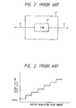
- Fig. 1 is a block diagram of a prior art moving-image signal encoding apparatus.
- Fig. 2 is a block diagram of the quantizer controller of Fig. 1.
- Fig. 3 is a diagram showing the relation between a quantization step size and a buffer remaining-code-amount in the apparatus of Fig. 1.
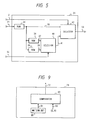
- Fig. 4 is a block diagram of a moving-image signal encoding apparatus according to an embodiment of this invention.
- Fig. 5 is a block diagram of the quantizer controller of Fig. 4.
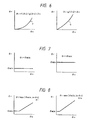
- Figs. 6-8 are diagrams showing relations between a refreshed-block quantization step size and a nonrefreshed-block quantization step size in the apparatus of Fig. 4.
- Fig. 9 is a block diagram of a portion of the variable-delay frame memory of Fig. 4.
- As shown in Fig. 4, a moving-image signal encoding apparatus according to an embodiment of this invention includes a
subtracter 1 which receives an inputdigital image signal 2 and aninter-frame prediction signal 3 and outputs a prediction error signal 4 equal to the difference between thesignals - A
refresh controller 5 receives atiming signal 6 and outputs arefresh instruction signal 7 in response to thetiming signal 6. A data-processingmode selector 8 receives theinput image signal 2, the prediction error signal 4, and therefresh instruction signal 7, and outputs achange control signal 9 dependent on thesignals mode selector 8 selects between inter-frame data processing and intra-frame data processing. Aswitch 10 receives theinput image signal 2, the prediction error signal 4, and thechange control signal 9. Theswitch 10 is connected to the input terminal of anorthogonal transform device 12. - The
switch 10 selects one of theinput image signal 2 and the prediction error signal 4, and transmits the selected signal to theorthogonal transform device 12 as asignal 11 to be subjected to orthogonal transform. - The
signal 11 selected by theswitch 10 is subjected to a predetermined orthogonal transformation by theorthogonal transform device 12 so that transform coefficients are generated on the basis of thesignal 11.Data 13 representing the transform coefficients are output from theorthogonal transform device 12. - A
quantizer 14 receives thetransform coefficient data 13 and alsodata 33 representing a quantization step size. Thequantizer 14 quantizes thetransform coefficient data 13 with the quantization step size represented by thedata 33, and converts thetransform coefficient data 13 intodata 16 representing second transform coefficients. Anencoder 17 receives the secondtransform coefficient data 16 and encodes thedata 16 into codeddata 18 of a predetermined format. The codeddata 18 are output from theencoder 17. Atransmission buffer 19 including a memory receives the codeddata 18 and temporarily stores it. The codeddata 18 are then output from thetransmission buffer 19 as atransmission signal 20. Thetransmission buffer 19 generates asignal 21 representing the amount of coded data remaining in the internal memory, that is, representing the size of an area of the internal memory which is occupied by the coded data. Aquantizer controller 31 receives therefreshment instruction signal 7, thesignal 21, and asignal 32 representative of moving/stationary information, and generates the quantizationstep size data 33 on the basis of thesignals step size data 33 are output from thequantizer controller 31 to thequantizer 14. As a result, the quantization step size used by thequantizer 14 is controlled in response to therefreshment instruction signal 7, thesignal 21, and the moving/stationary information signal 32. - An inverse
orthogonal transform device 23 receives the secondtransform coefficient data 16. The secondtransform coefficient data 16 are subjected by the inverseorthogonal transform device 23 to a predetermined inverse orthogonal transformation, and are converted back to areproduction signal 24. Thereproduction signal 24 is output from the inverseorthogonal transform device 23. Anadder 25 receives thereproduction signal 24. Aswitch 29 receives theinter-frame prediction signal 3, thechange control signal 9, and a zero signal representing "0". Theswitch 29 selects one of theinter-frame prediction signal 3 and the zero signal in response to thechange control signal 9, and outputs asignal 26 equal to the selected signal. Theadder 25 receives theoutput signal 26 from theswitch 29. Theadder 25 adds thereproduction signal 24 and theswitch output signal 26, and combines thesignals signal 27. Asection 28 including a variable-delay circuit and a frame memory receives the decodedsignal 27 and theinput image signal 2. The variable-delay frame memory 28 temporarily stores the decodedsignal 27, and generates theinter-frame prediction signal 3 and the moving/stationary information signal 32 on the basis of the stored decodedsignal 27 and theinput image signal 2. Theinter-frame prediction signal 3 and the moving/stationary information signal 32 are output from the variable-delay frame memory 28. As will be made clear later, theinter-frame prediction signal 3 is a motion-compensated signal. - The moving-image signal encoding apparatus of Fig 4 will be further described. A refresh process is executed for compensating for differences in accuracy between the encoder of the transmitter and the decoder of the receiver side, and also for compensating for errors in coded data which occur during the transmission of the data. One frame represented by the
signals refreshment controller 5 sends arefreshment instruction signal 7 in an active state to the data-processingmode selector 8 for each block which is to be refreshed. The ratio of the number of refreshed blocks in a frame to the total number of blocks in a frame is equal to a predetermined ratio chosen such that all the blocks will be refreshed in about 10 seconds. The period taken to refresh all the blocks is referred to as the refreshment period. - When the
refreshment instruction signal 7 is active, the data-processingmode selector 8 selects intra-frame data processing. When therefreshment instruction signal 7 is inactive, the data-processingmode selector 8 selects either inter-frame data processing or intra-frame data processing according to theinput image signal 2 and the prediction error signal 4. When intra-frame data processing is selected, theswitch 10 is controlled by thechange control signal 9 so that theinput image signal 2 will be selected by theswitch 9 to enable the intra-frame data processing. When inter-frame data processing is selected, theswitch 10 is controlled by thechange control signal 9 so that the prediction error signal 4 will be selected by theswitch 9 to enable the inter-frame data processing. - The
quantizer 14 is of the linear type. As described previously, thetransform coefficients 13 output from theorthogonal transform device 12 are quantized by thequantizer 14 with the quantization step size represented by thedata 33, so that thetransform coefficients 13 are converted by thequantizer 14 into thesecond transform coefficients 16. Thequantizer controller 31 varies the quantization step size in accordance with the amount of data remaining in the buffer, as represented by thesignal 21. Thequantizer 14 and theencoder 31 are related so that the number of bits of theoutput codes 18 from theencoder 17 will depend on the quantization step size used by thequantizer 14. Thequantizer 14, theencoder 17, thetransmission buffer 19, and thequantizer controller 31 form a closed-loop control circuit which serves to maintain the quantity (the amount or the number of bits) of coded data in thetransmission buffer 19 at or below a desired quantity. - As described previously, the signal selection by the
switch 29 is changed in response to thechange control signal 9. When inter-frame data processing is selected by the data-processingmode selector 8, theswitch 29 is controlled by thechange control signal 9 so that theinter-frame prediction signal 3 will be selected by theswitch 29 to enable the inter-frame data processing. When intra-frame data processing is selected by the data-processingmode selector 8, theswitch 29 is controlled by thechange control signal 9 so that the zero signal will be selected by theswitch 29 to enable the intra-frame data processing. Theoutput signal 26 from theswitch 29 and theoutput reproduction signal 24 from theinverse transform device 23 are combined into the decodedsignal 27 by theadder 25. The decodedsignal 27 is stored into a store section of the variable-delay frame memory 28. The variable-delay frame memory 28 has a motion detector which compares the stored decodedsignal 27 and theinput image signal 2, and which detects a motion vector on the basis of the result of the comparison between thesignals input image signal 2. The variable-delay frame memory 28 has a motion compensator which subjects the stored decodedsignal 27 to motion compensation in response to the motion vector, and thereby converts the stored decodedsignal 27 into the motion-compensatedinter-frame prediction signal 3. The detected motion vector is directly or indirectly used as the moving/stationary information signal 32. - As described previously, the
quantizer controller 31 controls the quantizationstep size data 33 in response to therefreshment signal 7, thesignal 21, and the moving/stationary information signal 32. Thequantizer controller 31 will be further described hereinafter. - As shown in Fig. 5, the
quantizer controller 31 includes aROM 34 storing data representing first different quantization step sizes arranged and designed for nonrefreshed blocks. Thesignal 21 is fed to theROM 34 as an address signal, and theROM 34outputs data 35 of a first quantization step size which varies as a function of the amount of data remaining in the buffer as represented by thesignal 21. The first quantizationstep size data 35 are fed to aselector 42 as nonrefreshed-block quantization step size data. - The
quantizer controller 31 also includesROMs ROM 36 stores data representing second different quantization step sizes arranged and designed for refreshed moving-region blocks. Characteristics of the second quantization step sizes in theROM 36 differ from characteristics of the first quantization step sizes in theROM 34. The first quantizationstep size data 35 are fed to theROM 36 as an address signal, and theROM 36outputs data 37 of a second quantization step size which varies as a function of the first quantization step size represented by thedata 35. TheROM 38 stores data representing third different quantization step sizes arranged and designed for refreshed stationary-region blocks. Characteristics of the third quantization step sizes in theROM 38 differ from characteristics of the first quantization step sizes in theROM 34, and also differ from characteristics of the second quantization step sizes in theROM 36. The first quantizationstep size data 35 are fed to theROM 38 as an address signal, and theROM 38outputs data 39 of a third quantization step size which varies as a function of the first quantization step size represented by thedata 35. The second quantizationstep size data 37 and the third quantizationstep size data 39 are fed to aselector 40. Theselector 40 receives the moving/stationary information signal 32. The moving/stationary information signal 32 represents whether the block corresponding to thetransform coefficient data 13 quantized by thequantizer 14 is in a moving part of the image or a stationary part of the image. Theselector 40 selects one of the second quantizationstep size data 37 and the third quantizationstep size data 39 in response to the moving/stationary information signal 32, and outputs the selected data as refreshed-block quantizationstep size data 41. Specifically, when the block corresponding to thetransform coefficient data 13 quantized by thequantizer 14 is from a moving image-part, the second quantizationstep size data 37 are selected by theselector 40. When the block corresponding to thetransform coefficient data 13 quantized by thequantizer 14 is from a stationary image-part, the third quantizationstep size data 39 are selected by theselector 40. The refreshed-block quantizationstep size data 41 are fed to theselector 42. - The
selector 42 receives therefreshment instruction signal 7. Therefreshment instruction signal 7 represents whether the block corresponding to thetransform coefficient data 13 quantized by thequantizer 14 is refreshed or not. Theselector 42 selects either the nonrefreshed-block quantizationstep size data 35 or the refreshed-block quantizationstep size data 41 in response to therefreshment instruction signal 7, and outputs the selected data as the quantizationstep size data 33. Specifically, when the block corresponding to thetransform coefficient data 13 quantized by thequantizer 14 is a nonrefreshed block, the nonrefreshed-block quantizationstep size data 35 are selected by theselector 42. When the block corresponding to thetransform coefficient data 13 quantized by thequantizer 14 is a refreshed block, the refreshed-block quantizationstep size data 41 are selected by theselector 42. - As understood from the previous description, in the case where the block corresponding to the
transform coefficient data 13 quantized by thequantizer 14 is a nonrefreshed block, the first quantization step size designed for a nonrefreshed block and output from theROM 34 is used by thequantizer 14. In the case where the block corresponding to thetransform coefficient data 13 quantized by thequantizer 14 is a refreshed moving-region block, the second quantization step size designed for a refreshed moving-region block and output from theROM 36 is used by thequantizer 14. In the case where the block corresponding to thetransform coefficient data 13 quantized by thequantizer 14 is a refreshed stationary-region block, the third quantization step size designed for a refreshed stationary-region block and output from theROM 38 is used by thequantizer 14. Thus, the quantization step size used by thequantizer 14 is changed in response to whether the block corresponding to thetransform coefficient data 13 quantized by thequantizer 14 agrees with a refreshed block or a nonrefreshed block. Therefore, refreshed blocks can be prevented from deteriorating in image quality. - A further description will be given of the relation between the nonrefreshed-block quantization step size and the refreshed-block quantization step size represented by the
data transform coefficient data 13 quantized by thequantizer 14 agrees with a stationary-region block, the refreshed-block quantization step size ϑr is smaller than the nonrefreshed-block quantization step size ϑn as is determined by a downwardly-facing convex function "f". As shown in the right-hand part of Fig. 6, in the case where the block corresponding to thetransform coefficient data 13 quantized by thequantizer 14 agrees with a moving-region block, the refreshed-block quantization step size ϑr is smaller than the nonrefreshed-block quantization step size ϑn as is determined by a downwardly-facing convex function "g". The values of the function "g" are greater than the corresponding values of the function "f". - It should be noted that the relation between the nonrefreshed-block quantization step size ϑn and the refreshed-block quantization step size ϑr may be modified as follows. According to a first modification, as shown in the left-hand part of Fig. 7, in the case where the block corresponding to the
transform coefficient data 13 quantized by thequantizer 14 is a stationary-region block, the refreshed-block quantization step size ϑr is fixed at a predetermined minimum value ϑmin while the nonrefreshed-block quantization step size ϑn varies. According to the first modification, as shown in the right-hand part of Fig. 7, in the case where the block corresponding to thetransform coefficient data 13 quantized by thequantizer 14 agrees with a moving-region block, the refreshed-block quantization step size ϑr is fixed at a predetermined value ϑmov while the nonrefreshed-block quantization step size ϑn varies. The predetermined value ϑmov is greater than the minimum value ϑmin. - According to a second modification, as shown in the left-hand part of Fig. 8, in the case where the block corresponding to the
transform coefficient data 13 quantized by thequantizer 14 agrees with a stationary-region block, the refreshed-block quantization step size ϑr is equal to the greater of the minimum value ϑmin and the product of a predetermined positive constant "a" and the nonrefreshed-block quantization step size ϑn. The constant "a" is smaller than 1. According to the second modification, as shown in the right-hand part of Fig 8, in the case where the block corresponding to thetransform coefficient data 13 quantized by thequantizer 14 agrees with a moving-region block, the refreshed-block quantization step size ϑr is equal to the greater of the minimum value ϑmin and the product of a predetermined positive constant "b" and the nonrefreshed-block quantization step size ϑn. The constant "b" is greater than the constant "a" but smaller than 1. - The generation of the moving/
stationary information signal 32 will be described hereinafter. As shown in Fig. 9, the variable-delay frame memory 28 includes amotion detector 80 generating data 81 representative of a motion vector for each of blocks composing a frame. The motion vector data 81 are output from themotion detector 80 to acomparator 82 within the variable-delay frame memory 28. The motion vector is expressed by a two-dimensional notation having horizontal and vertical components X and Y, and is denoted as (X,Y).Data 83 representing a predetermined vector (0,0), that is, a stationary-state-indicating vector, is fed to thecomparator 82. Thecomparator 82 compares the motion vector data 81 and the stationary-state vector data 83. When the motion vector data 81 differ from the stationary-state vector data 83, that is, when at least one of the components X and Y of the motion vector differs from "0", thecomparator 82 outputs a "1" signal as the moving/stationary information signal 32. When the motion vector data 81 are equal to the stationary-state vector data 83, that is, when both the components X and Y of the motion vector are equal to "0", thecomparator 82 outputs a "0" signal as the moving/stationary information signal 32.
Claims (6)
- A moving-image signal encoding apparatus comprising:a transmission buffer memory;means for determining a first quantization step size for a normal block other than a refreshed block on the basis of the occupied capacity of the buffer memory;means for determining a second quantization step size for the refreshed blocks on the basis of the first quantization step size;means for generating a refresh instruction signal; andmeans for selecting either of the first quantization step size or the second quantization step size according to the refresh instruction signal.
- A moving-image signal encoding apparatus comprising:a transmission buffer memory;means for determining a first quantization step size for a normal block other than a refreshed block on the basis of the occupied capacity of the buffer memory;means for determining a second quantization step size for the refreshed blocks in a moving region of the image on the basis of the first quantization step size;means for determining a third quantization step size for the refreshed blocks in a stationary region of the image on the basis of the first quantization step size;means for generating a refresh instruction signal;means for generating a moving/stationary information signal; andmeans for selecting one of the first quantization step size, the second quantization step size, and the third quantization step size in response to the refresh instruction signal and the moving/stationary information signal.
- A moving-image signal encoding apparatus comprising:means for refreshing a portion of image data;means for quantizing information in the image data with a variable quantization step size; andmeans for varying the quantization step size in the quantizing means in response to whether or not the information quantized by the quantizing means corresponds to the refreshed portion of the image data.
- An apparatus according to claim 3 further comprising means for, in cases where the information quantized by the quantizing means corresponds to the refreshed portion of the image data, varying the quantization step size in the quantizing means in response to whether the information quantized by the quantizing means relates to a moving image region or a stationary image region.
- The moving-image signal encoding apparatus of claim 3 further comprising means for encoding an output from the quantizing means, means for temporarily storing an output from the encoding means, and means for varying the quantization step size in the quantizing means in response to the size of the occupied area of the storing means.
- An apparatus for encoding a signal representative of a moving image and divided into blocks, the apparatus comprising:refresh means for refreshing some of the blocks of the signal;quantization means for quantizing said signal using a quantization step size to generate a quantized output signal;buffer means for temporarily storing the quantized output signal;first quantizer control means for generating a first quantization step size for nonrefreshed blocks on the basis of the amount of data stored by said buffer means; andsecond quantizer control means for generating a second quantization step for refreshed blocks on the basis of said first quantization step; whereinsaid quantization means is adapted to quantize blocks that have been refreshed using said second quantization step and to quantize blocks that have not been refreshed using said first quantization step.
Applications Claiming Priority (2)
| Application Number | Priority Date | Filing Date | Title |
|---|---|---|---|
| JP1330622A JPH0714209B2 (en) | 1989-12-20 | 1989-12-20 | Video coding device |
| JP330622/89 | 1989-12-20 |
Publications (3)
| Publication Number | Publication Date |
|---|---|
| EP0434427A2 true EP0434427A2 (en) | 1991-06-26 |
| EP0434427A3 EP0434427A3 (en) | 1993-05-12 |
| EP0434427B1 EP0434427B1 (en) | 1996-04-03 |
Family
ID=18234722
Family Applications (1)
| Application Number | Title | Priority Date | Filing Date |
|---|---|---|---|
| EP90314020A Expired - Lifetime EP0434427B1 (en) | 1989-12-20 | 1990-12-20 | Moving-image signal encoding apparatus |
Country Status (4)
| Country | Link |
|---|---|
| US (1) | US5089888A (en) |
| EP (1) | EP0434427B1 (en) |
| JP (1) | JPH0714209B2 (en) |
| DE (1) | DE69026357T2 (en) |
Cited By (15)
| Publication number | Priority date | Publication date | Assignee | Title |
|---|---|---|---|---|
| GB2261567A (en) * | 1991-11-15 | 1993-05-19 | Televerket | Method and device for image coding of a video signal |
| EP0554086A2 (en) * | 1992-01-29 | 1993-08-04 | Mitsubishi Denki Kabushiki Kaisha | High-efficiency encoder and video information recording/reproducing apparatus |
| EP0558259A2 (en) * | 1992-02-24 | 1993-09-01 | Sony Corporation | Video signal transmission |
| FR2691272A1 (en) * | 1992-05-15 | 1993-11-19 | Thomson Csf | Coding procedure for blocks of coding images with low output - involves assessing cost of employing alternative coding modes so that use of intra=image coding is minimised |
| EP0579450A2 (en) * | 1992-07-14 | 1994-01-19 | Canon Kabushiki Kaisha | An image encoding device |
| EP0588653A2 (en) * | 1992-09-16 | 1994-03-23 | Fujitsu Limited | Image data coding and restoring method and appatatus for coding and restoring the same |
| US5488482A (en) * | 1992-01-29 | 1996-01-30 | Mitsubishi Denki Kabushiki Kaisha | High-efficiency encoder and video information recording/reproducing apparatus |
| WO2001072046A1 (en) * | 2000-03-21 | 2001-09-27 | Koninklijke Philips Electronics N.V. | Variable bit rate video encoding method and device |
| US6870884B1 (en) | 1992-01-29 | 2005-03-22 | Mitsubishi Denki Kabushiki Kaisha | High-efficiency encoder and video information recording/reproducing apparatus |
| EP1761070A1 (en) * | 1995-10-27 | 2007-03-07 | Kabushiki Kaisha Toshiba | Video encoding and decoding apparatus |
| EP2334079A1 (en) * | 2008-09-29 | 2011-06-15 | Panasonic Corporation | Method for encoding moving picture and moving picture encoding device |
| WO2012097100A1 (en) * | 2011-01-13 | 2012-07-19 | Qualcomm Incorporated | Coding static video data with a baseline encoder |
| EP2904796A4 (en) * | 2012-10-03 | 2016-06-08 | Broadcom Corp | Bounded rate compression with rate control for slices |
| US9451250B2 (en) | 2012-10-03 | 2016-09-20 | Broadcom Corporation | Bounded rate compression with rate control for slices |
| US9883180B2 (en) | 2012-10-03 | 2018-01-30 | Avago Technologies General Ip (Singapore) Pte. Ltd. | Bounded rate near-lossless and lossless image compression |
Families Citing this family (39)
| Publication number | Priority date | Publication date | Assignee | Title |
|---|---|---|---|---|
| US5164828A (en) * | 1990-02-26 | 1992-11-17 | Sony Corporation | Video signal transmission and method and apparatus for coding video signal used in this |
| US5291282A (en) * | 1990-04-19 | 1994-03-01 | Olympus Optical Co., Ltd. | Image data coding apparatus and method capable of controlling amount of codes |
| JP2514115B2 (en) * | 1991-02-15 | 1996-07-10 | 株式会社グラフィックス・コミュニケーション・テクノロジーズ | Image signal encoder |
| JP3109854B2 (en) * | 1991-04-23 | 2000-11-20 | キヤノン株式会社 | Image coding method and apparatus |
| JP3338460B2 (en) * | 1991-05-09 | 2002-10-28 | ソニー株式会社 | Video signal encoding device and video signal encoding method |
| US5369437A (en) * | 1991-08-28 | 1994-11-29 | Nec Corporation | Time-varying image signal coding/decoding system |
| US6041144A (en) * | 1991-09-17 | 2000-03-21 | Canon Kabushiki Kaisha | Image processing apparatus |
| JPH0595540A (en) * | 1991-09-30 | 1993-04-16 | Sony Corp | Dynamic picture encoder |
| KR100255528B1 (en) * | 1991-10-31 | 2000-05-01 | 요트.게.아. 롤페즈 | Television system for transmitting digitized television pictures from a transmitter to a receiver |
| US5534927A (en) * | 1991-11-12 | 1996-07-09 | Nippon Hoso Kyokai | Method of performing high efficiency coding of image signal and system therefor |
| JPH05137131A (en) * | 1991-11-13 | 1993-06-01 | Sony Corp | Inter-frame motion predicting method |
| KR930015851A (en) * | 1991-12-31 | 1993-07-24 | 배순훈 | Image compression transmission device with field and frame selection |
| JP2894067B2 (en) * | 1992-02-26 | 1999-05-24 | 日本電気株式会社 | Moving picture coding control method and moving picture coding apparatus |
| US5283646A (en) * | 1992-04-09 | 1994-02-01 | Picturetel Corporation | Quantizer control method and apparatus |
| US5440344A (en) * | 1992-04-28 | 1995-08-08 | Mitsubishi Denki Kabushiki Kaisha | Video encoder using adjacent pixel difference for quantizer control |
| ES2278378T3 (en) * | 1992-06-09 | 2007-08-01 | Canon Kabushiki Kaisha | CODING DEVICE. |
| JP3443867B2 (en) * | 1992-06-26 | 2003-09-08 | ソニー株式会社 | Image signal encoding / decoding method and image signal recording medium |
| US5982437A (en) * | 1992-10-26 | 1999-11-09 | Sony Corporation | Coding method and system, and decoding method and system |
| US5663763A (en) * | 1992-10-29 | 1997-09-02 | Sony Corp. | Picture signal encoding method and apparatus and picture signal decoding method and apparatus |
| KR0166727B1 (en) * | 1992-11-27 | 1999-03-20 | 김광호 | The encoding method and apparatus for quantization control with the information of image motion |
| JP3165296B2 (en) * | 1992-12-25 | 2001-05-14 | 三菱電機株式会社 | Inter-frame coding processing method, inter-frame coding processing method, and coding control method |
| KR0162203B1 (en) * | 1993-06-21 | 1998-12-15 | 김광호 | Adaptive encoding method and device using quantization step size |
| EP0660619A1 (en) * | 1993-12-22 | 1995-06-28 | Laboratoires D'electronique Philips S.A.S. | Method for image variable length coding and device for carrying such method |
| KR100358021B1 (en) * | 1994-02-01 | 2003-01-24 | 산요 덴키 가부시키가이샤 | Method of converting 2D image into 3D image and stereoscopic image display system |
| JP2882287B2 (en) * | 1994-08-22 | 1999-04-12 | 日本電気株式会社 | Video encoding device |
| JP3954656B2 (en) * | 1994-09-29 | 2007-08-08 | ソニー株式会社 | Image coding apparatus and method |
| KR0170937B1 (en) * | 1994-12-14 | 1999-03-20 | 배순훈 | Image data encoder |
| KR970057995A (en) * | 1995-12-30 | 1997-07-31 | 배순훈 | Dequantizer Optimizer in MPEG Decoder |
| US5731837A (en) | 1996-01-25 | 1998-03-24 | Thomson Multimedia, S.A. | Quantization circuitry as for video signal compression systems |
| US5786856A (en) * | 1996-03-19 | 1998-07-28 | International Business Machines | Method for adaptive quantization by multiplication of luminance pixel blocks by a modified, frequency ordered hadamard matrix |
| JPH1079948A (en) * | 1996-09-03 | 1998-03-24 | Mitsubishi Electric Corp | Image encoding device |
| US6961375B1 (en) * | 1997-02-06 | 2005-11-01 | Sony Corporation | Picture coding device and method, picture transmitting device and method and recording medium |
| JP3209171B2 (en) | 1998-01-08 | 2001-09-17 | 日本電気株式会社 | Video encoding device |
| US6956899B2 (en) * | 1998-03-23 | 2005-10-18 | International Business Machines Corporation | Precise bit control apparatus with look-ahead for MPEG encoding |
| CN100534196C (en) * | 2004-05-25 | 2009-08-26 | Nxp股份有限公司 | Method and device for encoding digital video data |
| JP4515870B2 (en) * | 2004-09-24 | 2010-08-04 | パナソニック株式会社 | Signal processing apparatus and video system |
| JP2006295852A (en) * | 2005-04-14 | 2006-10-26 | Sony Corp | Image coder, image coding method, imaging apparatus, and program |
| US10752008B2 (en) * | 2015-12-28 | 2020-08-25 | Seiko Epson Corporation | Liquid supply unit |
| CN112165619A (en) * | 2020-09-24 | 2021-01-01 | 杭州当虹科技股份有限公司 | Method for compressed storage of surveillance video |
Citations (3)
| Publication number | Priority date | Publication date | Assignee | Title |
|---|---|---|---|---|
| JPS6146685A (en) * | 1984-08-13 | 1986-03-06 | Nec Corp | Prediction encoder of moving picture signal |
| US4731664A (en) * | 1984-11-08 | 1988-03-15 | Nec Corporation | Method and arrangement for refreshing a frame memory in an interframe encoding system |
| US4888640A (en) * | 1988-05-16 | 1989-12-19 | General Electric Company | Refresh system for digital signals |
Family Cites Families (2)
| Publication number | Priority date | Publication date | Assignee | Title |
|---|---|---|---|---|
| JPH082106B2 (en) * | 1986-11-10 | 1996-01-10 | 国際電信電話株式会社 | Hybrid coding method for moving image signals |
| US4831439A (en) * | 1988-05-16 | 1989-05-16 | General Electric Company | Refresh system for digital signals with refresh cycle synchronization |
-
1989
- 1989-12-20 JP JP1330622A patent/JPH0714209B2/en not_active Expired - Fee Related
-
1990
- 1990-12-14 US US07/628,697 patent/US5089888A/en not_active Ceased
- 1990-12-20 EP EP90314020A patent/EP0434427B1/en not_active Expired - Lifetime
- 1990-12-20 DE DE69026357T patent/DE69026357T2/en not_active Expired - Fee Related
Patent Citations (3)
| Publication number | Priority date | Publication date | Assignee | Title |
|---|---|---|---|---|
| JPS6146685A (en) * | 1984-08-13 | 1986-03-06 | Nec Corp | Prediction encoder of moving picture signal |
| US4731664A (en) * | 1984-11-08 | 1988-03-15 | Nec Corporation | Method and arrangement for refreshing a frame memory in an interframe encoding system |
| US4888640A (en) * | 1988-05-16 | 1989-12-19 | General Electric Company | Refresh system for digital signals |
Non-Patent Citations (1)
| Title |
|---|
| PATENT ABSTRACTS OF JAPAN vol. 10, no. 205 (E-420)(2261) 17 July 1986 & JP-A-61 46 685 ( NEC CORP ) 6 March 1986 * |
Cited By (52)
| Publication number | Priority date | Publication date | Assignee | Title |
|---|---|---|---|---|
| GB2261567B (en) * | 1991-11-15 | 1995-04-19 | Televerket | Method and device for image coding of a video signal |
| GB2261567A (en) * | 1991-11-15 | 1993-05-19 | Televerket | Method and device for image coding of a video signal |
| US5966181A (en) * | 1991-11-15 | 1999-10-12 | Televerket | Video coding system with buffer control quantization step size |
| US7688892B2 (en) | 1992-01-29 | 2010-03-30 | Mitsubishi Denki Kabushiki Kaisha | High efficiency encoder and video information recording/reproducing apparatus |
| US7756202B2 (en) | 1992-01-29 | 2010-07-13 | Mitsubishi Denki Kabushiki Kaisha | High-efficiency encoder and video information recording/reproducing apparatus |
| US7936817B2 (en) | 1992-01-29 | 2011-05-03 | Mitsubishi Denki Kabushiki Kaisha | High-efficiency encoder and video information recording/reproducing apparatus |
| EP0554086A2 (en) * | 1992-01-29 | 1993-08-04 | Mitsubishi Denki Kabushiki Kaisha | High-efficiency encoder and video information recording/reproducing apparatus |
| EP1971130A1 (en) * | 1992-01-29 | 2008-09-17 | Mitsubishi Denki Kabushiki Kaisha | High-efficiency encoder and video information recording/reproducing apparatus |
| US7376184B2 (en) | 1992-01-29 | 2008-05-20 | Mitsubishi Denki Kabushiki Kaisha | High-efficiency encoder and video information recording/reproducing apparatus |
| US6870884B1 (en) | 1992-01-29 | 2005-03-22 | Mitsubishi Denki Kabushiki Kaisha | High-efficiency encoder and video information recording/reproducing apparatus |
| US7362805B2 (en) | 1992-01-29 | 2008-04-22 | Mitsubishi Denki Kabushiki Kaisha | High efficiency encoder and video information recording/reproducing apparatus |
| US5479264A (en) * | 1992-01-29 | 1995-12-26 | Mitsubishi Denki Kabushiki Kaisha | High-efficiency encoder and video information recording/reproducing apparatus |
| US5488482A (en) * | 1992-01-29 | 1996-01-30 | Mitsubishi Denki Kabushiki Kaisha | High-efficiency encoder and video information recording/reproducing apparatus |
| US7336708B2 (en) | 1992-01-29 | 2008-02-26 | Mitsubishi Denki Kabushiki Kaisha | High-efficiency encoder and video information recording/reproducing apparatus |
| EP1555830A2 (en) * | 1992-01-29 | 2005-07-20 | Mitsubishi Denki Kabushiki Kaisha | High-Efficiency encoder and video information recording/reproducing apparatus |
| US5841474A (en) * | 1992-01-29 | 1998-11-24 | Mitsubshi Denki Kabushiki Kaisha | High-efficiency encoder and video information recording/reproducing apparatus |
| EP1555817A3 (en) * | 1992-01-29 | 2005-09-07 | Mitsubishi Denki Kabushiki Kaisha | High-efficiency encoder and video information recording/reproducing apparatus |
| EP1555830A3 (en) * | 1992-01-29 | 2005-09-07 | Mitsubishi Denki Kabushiki Kaisha | High-Efficiency encoder and video information recording/reproducing apparatus |
| EP1555817A2 (en) * | 1992-01-29 | 2005-07-20 | Mitsubishi Denki Kabushiki Kaisha | High-efficiency encoder and video information recording/reproducing apparatus |
| US5909252A (en) * | 1992-01-29 | 1999-06-01 | Mitsubishi Denki Kabushiki Kaisha | High efficiency encoder and video information recording/reproducing apparatus |
| EP0554086A3 (en) * | 1992-01-29 | 1994-12-07 | Mitsubishi Electric Corp | High-efficiency encoder and video information recording/reproducing apparatus |
| EP1137280A1 (en) * | 1992-01-29 | 2001-09-26 | Mitsubishi Denki Kabushiki Kaisha | High-efficiency encoder and video information recording/reproducing apparatus |
| EP1304884A3 (en) * | 1992-01-29 | 2003-05-14 | Mitsubishi Denki Kabushiki Kaisha | High-efficiency encoder and video information recording/reproducing apparatus |
| EP1296521A3 (en) * | 1992-01-29 | 2003-05-14 | Mitsubishi Denki Kabushiki Kaisha | High-efficiency encoder and video information recording/reproducing apparatus |
| EP1296521A2 (en) * | 1992-01-29 | 2003-03-26 | Mitsubishi Denki Kabushiki Kaisha | High-efficiency encoder and video information recording/reproducing apparatus |
| EP1304884A2 (en) * | 1992-01-29 | 2003-04-23 | Mitsubishi Denki Kabushiki Kaisha | High-efficiency encoder and video information recording/reproducing apparatus |
| US5822006A (en) * | 1992-02-24 | 1998-10-13 | Sony Corporation | Video signal transmission method and apparatus employing variable quantization |
| EP0558259A2 (en) * | 1992-02-24 | 1993-09-01 | Sony Corporation | Video signal transmission |
| EP0558259A3 (en) * | 1992-02-24 | 1994-06-29 | Sony Corp | Video signal transmission |
| FR2691272A1 (en) * | 1992-05-15 | 1993-11-19 | Thomson Csf | Coding procedure for blocks of coding images with low output - involves assessing cost of employing alternative coding modes so that use of intra=image coding is minimised |
| EP0579450A2 (en) * | 1992-07-14 | 1994-01-19 | Canon Kabushiki Kaisha | An image encoding device |
| US5825931A (en) * | 1992-07-14 | 1998-10-20 | Canon Kabushiki Kaisha | Image encoding device |
| EP0579450A3 (en) * | 1992-07-14 | 1994-07-06 | Canon Kk | An image encoding device |
| EP0899959A3 (en) * | 1992-09-16 | 1999-03-10 | Fujitsu Limited | Image data coding and restoring method and apparatus for coding and restoring the same |
| US5861922A (en) * | 1992-09-16 | 1999-01-19 | Fujitsu Ltd. | Image data coding and restoring method and apparatus for coding and restoring the same |
| US6304606B1 (en) | 1992-09-16 | 2001-10-16 | Fujitsu Limited | Image data coding and restoring method and apparatus for coding and restoring the same |
| EP0899959A2 (en) * | 1992-09-16 | 1999-03-03 | Fujitsu Limited | Image data coding and restoring method and apparatus for coding and restoring the same |
| EP0588653A3 (en) * | 1992-09-16 | 1994-09-28 | Fujitsu Ltd | Image data coding and restoring method and apparatus for coding and restoring the same |
| EP0588653A2 (en) * | 1992-09-16 | 1994-03-23 | Fujitsu Limited | Image data coding and restoring method and appatatus for coding and restoring the same |
| EP1761070A1 (en) * | 1995-10-27 | 2007-03-07 | Kabushiki Kaisha Toshiba | Video encoding and decoding apparatus |
| US7054363B2 (en) | 2000-03-21 | 2006-05-30 | Koninklijke Philips Electronics N.V. | Variable bit rate video encoding method and device |
| WO2001072046A1 (en) * | 2000-03-21 | 2001-09-27 | Koninklijke Philips Electronics N.V. | Variable bit rate video encoding method and device |
| EP2334079A4 (en) * | 2008-09-29 | 2012-03-28 | Panasonic Corp | Method for encoding moving picture and moving picture encoding device |
| CN102106147A (en) * | 2008-09-29 | 2011-06-22 | 松下电器产业株式会社 | Method for encoding moving picture and moving picture encoding device |
| EP2334079A1 (en) * | 2008-09-29 | 2011-06-15 | Panasonic Corporation | Method for encoding moving picture and moving picture encoding device |
| CN102106147B (en) * | 2008-09-29 | 2013-06-19 | 松下电器产业株式会社 | Method for encoding moving picture and moving picture encoding device |
| US8948255B2 (en) | 2008-09-29 | 2015-02-03 | Panasonic Intellectual Property Management Co., Ltd. | Moving picture coding method for quantizing a plurality of pictures using a quantization step and a small quantization step having a size smaller than a size of the quantization step |
| WO2012097100A1 (en) * | 2011-01-13 | 2012-07-19 | Qualcomm Incorporated | Coding static video data with a baseline encoder |
| EP2904796A4 (en) * | 2012-10-03 | 2016-06-08 | Broadcom Corp | Bounded rate compression with rate control for slices |
| US9451250B2 (en) | 2012-10-03 | 2016-09-20 | Broadcom Corporation | Bounded rate compression with rate control for slices |
| US9883180B2 (en) | 2012-10-03 | 2018-01-30 | Avago Technologies General Ip (Singapore) Pte. Ltd. | Bounded rate near-lossless and lossless image compression |
| US10812829B2 (en) | 2012-10-03 | 2020-10-20 | Avago Technologies International Sales Pte. Limited | 2D block image encoding |
Also Published As
| Publication number | Publication date |
|---|---|
| DE69026357T2 (en) | 1996-09-05 |
| DE69026357D1 (en) | 1996-05-09 |
| EP0434427A3 (en) | 1993-05-12 |
| JPH0714209B2 (en) | 1995-02-15 |
| EP0434427B1 (en) | 1996-04-03 |
| JPH03190482A (en) | 1991-08-20 |
| US5089888A (en) | 1992-02-18 |
Similar Documents
| Publication | Publication Date | Title |
|---|---|---|
| EP0434427B1 (en) | Moving-image signal encoding apparatus | |
| US4833535A (en) | Image transmission apparatus | |
| US5764296A (en) | Resolution-variable adaptive picture compression | |
| US5657087A (en) | Motion compensation encoding method and apparatus adaptive to motion amount | |
| EP0556507B1 (en) | Image signal coding and decoding apparatus | |
| EP0595599B1 (en) | Compression/decompression system for image data | |
| JP3716931B2 (en) | Adaptive decoding device for continuous images | |
| US5263100A (en) | Image coding method and apparatus | |
| US6542642B2 (en) | Image coding process and motion detecting process using bidirectional prediction | |
| KR100225542B1 (en) | Method and apparatus for image signal encoding | |
| EP0786905A2 (en) | Quantization circuitry as for video signal compression systems | |
| US5241401A (en) | Image signal encoding apparatus and method for controlling quantization step size in accordance with frame skip numbers | |
| EP0859520A1 (en) | Video signal coding systems and processes using adaptive quantization | |
| US5689307A (en) | Encoding and decoding systems for transmitting moving pictures | |
| US4683494A (en) | Inter-frame predictive coding apparatus for video signal | |
| US5534929A (en) | Data processing apparatus | |
| US6269123B1 (en) | Video encoder and video encoding method | |
| JPS61118085A (en) | Coding system and device for picture signal | |
| US5521643A (en) | Adaptively coding method and apparatus utilizing variation in quantization step size | |
| EP0542288B1 (en) | Adaptive quantization apparatus | |
| US5396292A (en) | Encoding apparatus for motion video signals | |
| US6724821B1 (en) | Picture coding apparatus with coding efficiency improved | |
| US5508745A (en) | Apparatus for controlling a quantization level to be modified by a motion vector | |
| US5394190A (en) | Video signal encoding apparatus | |
| USRE36680E (en) | Moving-image signal encoding apparatus with variably selected quantization step size |
Legal Events
| Date | Code | Title | Description |
|---|---|---|---|
| PUAI | Public reference made under article 153(3) epc to a published international application that has entered the european phase |
Free format text: ORIGINAL CODE: 0009012 |
|
| 17P | Request for examination filed |
Effective date: 19901231 |
|
| AK | Designated contracting states |
Kind code of ref document: A2 Designated state(s): DE GB SE |
|
| PUAL | Search report despatched |
Free format text: ORIGINAL CODE: 0009013 |
|
| AK | Designated contracting states |
Kind code of ref document: A3 Designated state(s): DE GB SE |
|
| 17Q | First examination report despatched |
Effective date: 19950120 |
|
| GRAH | Despatch of communication of intention to grant a patent |
Free format text: ORIGINAL CODE: EPIDOS IGRA |
|
| GRAA | (expected) grant |
Free format text: ORIGINAL CODE: 0009210 |
|
| AK | Designated contracting states |
Kind code of ref document: B1 Designated state(s): DE GB SE |
|
| REF | Corresponds to: |
Ref document number: 69026357 Country of ref document: DE Date of ref document: 19960509 |
|
| PLBE | No opposition filed within time limit |
Free format text: ORIGINAL CODE: 0009261 |
|
| STAA | Information on the status of an ep patent application or granted ep patent |
Free format text: STATUS: NO OPPOSITION FILED WITHIN TIME LIMIT |
|
| 26N | No opposition filed | ||
| REG | Reference to a national code |
Ref country code: GB Ref legal event code: IF02 |
|
| PGFP | Annual fee paid to national office [announced via postgrant information from national office to epo] |
Ref country code: SE Payment date: 20041206 Year of fee payment: 15 |
|
| PGFP | Annual fee paid to national office [announced via postgrant information from national office to epo] |
Ref country code: GB Payment date: 20041215 Year of fee payment: 15 |
|
| PGFP | Annual fee paid to national office [announced via postgrant information from national office to epo] |
Ref country code: DE Payment date: 20041216 Year of fee payment: 15 |
|
| PG25 | Lapsed in a contracting state [announced via postgrant information from national office to epo] |
Ref country code: GB Free format text: LAPSE BECAUSE OF NON-PAYMENT OF DUE FEES Effective date: 20051220 |
|
| PG25 | Lapsed in a contracting state [announced via postgrant information from national office to epo] |
Ref country code: SE Free format text: LAPSE BECAUSE OF NON-PAYMENT OF DUE FEES Effective date: 20051221 |
|
| PG25 | Lapsed in a contracting state [announced via postgrant information from national office to epo] |
Ref country code: DE Free format text: LAPSE BECAUSE OF NON-PAYMENT OF DUE FEES Effective date: 20060701 |
|
| EUG | Se: european patent has lapsed | ||
| GBPC | Gb: european patent ceased through non-payment of renewal fee |
Effective date: 20051220 |