EP0435565B1 - Ink jet printer - Google Patents
Ink jet printer Download PDFInfo
- Publication number
- EP0435565B1 EP0435565B1 EP90313969A EP90313969A EP0435565B1 EP 0435565 B1 EP0435565 B1 EP 0435565B1 EP 90313969 A EP90313969 A EP 90313969A EP 90313969 A EP90313969 A EP 90313969A EP 0435565 B1 EP0435565 B1 EP 0435565B1
- Authority
- EP
- European Patent Office
- Prior art keywords
- printhead
- heater
- heat sink
- temperature
- temperature sensor
- Prior art date
- Legal status (The legal status is an assumption and is not a legal conclusion. Google has not performed a legal analysis and makes no representation as to the accuracy of the status listed.)
- Expired - Lifetime
Links
Images


Classifications
-
- B—PERFORMING OPERATIONS; TRANSPORTING
- B41—PRINTING; LINING MACHINES; TYPEWRITERS; STAMPS
- B41J—TYPEWRITERS; SELECTIVE PRINTING MECHANISMS, i.e. MECHANISMS PRINTING OTHERWISE THAN FROM A FORME; CORRECTION OF TYPOGRAPHICAL ERRORS
- B41J2/00—Typewriters or selective printing mechanisms characterised by the printing or marking process for which they are designed
- B41J2/005—Typewriters or selective printing mechanisms characterised by the printing or marking process for which they are designed characterised by bringing liquid or particles selectively into contact with a printing material
- B41J2/01—Ink jet
- B41J2/015—Ink jet characterised by the jet generation process
- B41J2/04—Ink jet characterised by the jet generation process generating single droplets or particles on demand
- B41J2/045—Ink jet characterised by the jet generation process generating single droplets or particles on demand by pressure, e.g. electromechanical transducers
- B41J2/04501—Control methods or devices therefor, e.g. driver circuits, control circuits
- B41J2/04541—Specific driving circuit
-
- B—PERFORMING OPERATIONS; TRANSPORTING
- B41—PRINTING; LINING MACHINES; TYPEWRITERS; STAMPS
- B41J—TYPEWRITERS; SELECTIVE PRINTING MECHANISMS, i.e. MECHANISMS PRINTING OTHERWISE THAN FROM A FORME; CORRECTION OF TYPOGRAPHICAL ERRORS
- B41J2/00—Typewriters or selective printing mechanisms characterised by the printing or marking process for which they are designed
- B41J2/005—Typewriters or selective printing mechanisms characterised by the printing or marking process for which they are designed characterised by bringing liquid or particles selectively into contact with a printing material
- B41J2/01—Ink jet
- B41J2/015—Ink jet characterised by the jet generation process
- B41J2/04—Ink jet characterised by the jet generation process generating single droplets or particles on demand
- B41J2/045—Ink jet characterised by the jet generation process generating single droplets or particles on demand by pressure, e.g. electromechanical transducers
- B41J2/04501—Control methods or devices therefor, e.g. driver circuits, control circuits
- B41J2/04563—Control methods or devices therefor, e.g. driver circuits, control circuits detecting head temperature; Ink temperature
-
- B—PERFORMING OPERATIONS; TRANSPORTING
- B41—PRINTING; LINING MACHINES; TYPEWRITERS; STAMPS
- B41J—TYPEWRITERS; SELECTIVE PRINTING MECHANISMS, i.e. MECHANISMS PRINTING OTHERWISE THAN FROM A FORME; CORRECTION OF TYPOGRAPHICAL ERRORS
- B41J2/00—Typewriters or selective printing mechanisms characterised by the printing or marking process for which they are designed
- B41J2/005—Typewriters or selective printing mechanisms characterised by the printing or marking process for which they are designed characterised by bringing liquid or particles selectively into contact with a printing material
- B41J2/01—Ink jet
- B41J2/015—Ink jet characterised by the jet generation process
- B41J2/04—Ink jet characterised by the jet generation process generating single droplets or particles on demand
- B41J2/045—Ink jet characterised by the jet generation process generating single droplets or particles on demand by pressure, e.g. electromechanical transducers
- B41J2/04501—Control methods or devices therefor, e.g. driver circuits, control circuits
- B41J2/0458—Control methods or devices therefor, e.g. driver circuits, control circuits controlling heads based on heating elements forming bubbles
-
- B—PERFORMING OPERATIONS; TRANSPORTING
- B41—PRINTING; LINING MACHINES; TYPEWRITERS; STAMPS
- B41J—TYPEWRITERS; SELECTIVE PRINTING MECHANISMS, i.e. MECHANISMS PRINTING OTHERWISE THAN FROM A FORME; CORRECTION OF TYPOGRAPHICAL ERRORS
- B41J2/00—Typewriters or selective printing mechanisms characterised by the printing or marking process for which they are designed
- B41J2/005—Typewriters or selective printing mechanisms characterised by the printing or marking process for which they are designed characterised by bringing liquid or particles selectively into contact with a printing material
- B41J2/01—Ink jet
- B41J2/135—Nozzles
- B41J2/14—Structure thereof only for on-demand ink jet heads
- B41J2002/14379—Edge shooter
Description
- This invention relates to a bubble ink jet printing system and, more particularly, to a printhead which is constructed so as to control effectively heat generated during the printing operation.
- Bubble jet printing is a drop-on-demand type of ink jet printing which uses thermal energy to produce a vapor bubble in an ink-filled channel that expels a droplet. A thermal energy generator is located in the channels near the nozzle a predetermined distance therefrom. A plurality of resistors are individually addressed with a current pulse to vaporize some ink momentarily to form the bubble. As the bubble grows, ink bulges from a respective nozzle, being contained by the surface tension of the ink. As the bubble begins to collapse, the ink still in the channel between the nozzle and bubble starts to retract towards the collapsing bubble, causing a volumetric contraction of the ink at the nozzle, resulting in the separation of a droplet of ink from the the dwindling bulge. The acceleration of the ink out of the nozzle when the bubble is growing provides the momentum of the droplet, which moves in a substantially-straight line towards a record medium, such as paper.
- A problem with known printhead operation is the increase in temperature experienced by a printhead during an operational mode. With continued operation, the printhead begins to heat up, and the diameter of the ink droplet begins to increase, resulting in excessive drop overlap on the record medium thereby degrading image quality. As the printhead experiences a further heat buildup, the ink temperature may rise to a point where air ingestion at the nozzle halts drop formation completely. It has been found that, at about 65°c for a typical ink, printhead operation becomes unreliable. There is also a lower temperature limit for reliable operation, which varies for different inks and device geometries. This limit might, for example, be about 20°C for an ink and device designed to function reliably up to, for example, 60°C. At the same time, it is desirable to offer an extended range of ambient operating temperatures, such as 5°C to 35°C, so that it will be necessary to provide for warming up the printhead. It is also desirable to minimize the time required to warm up the printhead, so that first copy (print) out time is acceptable. The printhead characteristics and machine environment requirements have the following impact on the thermal design of the system. The generation of heat during operation (which becomes a greater problem as print speed, duration, and density increase) makes it necessary that the printhead be connected to a heat sink, which is efficient in transferring heat away from the printhead. The efficiency of the heat transfer away from the printhead will be aided increasingly, the cooler the heat sink is relative to the printhead. Because of the range of ambient temperatures to be encountered (assumed to be 5°C to 35°C, but not limited to that range), because of the temperature uniformity requirement, and because it is less complicated (cheaper) to control temperature by heating than by cooling, it is advantageous to set the nominal printhead operating temperature at or near the maximum ambient temperature encountered. Because of the desired minimal first copy (print) out time, as well as the desired efficiency of the heat sink, it is also advantageous to situate the temperature sensor and heater as close as possible (thermally) to the printhead, and as far as possible (thermally) from the heat sink.
- Various techniques are known to control heat buildup and maintain the printhead within a reasonable printing temperature range. US-A-4,496,824 discloses a thermal printer which includes circuitry to measure printhead temperature, compare the temperature to values representing a desired temperature range and reduce the printhead temperature by activation of a cooling mechanism.
- US-A-4,571,598 discloses a thermal printhead in which a heat sink and ceramic substrate are connected to heating elements formed on the substrate surface.
- More exact temperature regulation is obtained, however, by using a combination of a temperature sensor and a heater in a feedback loop tied into the printhead power source. For example, US-A-4,250,512 discloses a heating device for a mosaic recorder comprised of both a heater and a temperature sensor disposed in the immediate vicinity of ink ducts in a recording head. The heater and sensor function to monitor and regulate the temperature of a recording head during operation. Column 3, lines 7-24 describe how a temperature sensor, a thermistor, a heating element, and a resistor operate in unison to maintain the recording head at an optimum operational temperature to maximize printing efficiency. US-A-4,125,845 discloses an ink jet printhead temperature control circuit which uses a heater and a temperature sensing device to maintain a recording head temperature above the preset temperature level. An output from the temperature-sensing device drives an electrical heater which regulates the recording head temperature The temperature-sensing device is a resistive element attached to the bottom side of the printhead by thick film techniques. US-A-4,704,620 discloses a temperature control system for an ink jet printer wherein the temperature of an ink jet printhead is controlled by a heater and a temperature sensor which collectively regulate heat transfer to maintain an ink jet printhead within an optimum stable discharge temperature range. The temperature control circuit, as shown in Figure 7 of the patent, utilizes an output from a comparator circuit and control signals from a signal processing circuit to regulate printhead temperature based on the output from the temperature sensor. US-A-4,791,435 discloses a thermal ink jet printhead temperature control system which regulates the temperature of a printhead via a temperature-sensing device and a heating component. The temperature-sensing device, comprised of either a collection of transducers or a single thermistor, closely estimates the temperature of the ink jet printhead and compensates for an unacceptably-low printhead temperature by either cooling or heating the printhead as needed. US-A-4,686,544 discloses a temperature control system for "drop-on-demand" ink jet printers wherein a heat generating electrode, positioned between layers of insulating and resistive material of a printhead substrate, controls the temperature of the printhead during operation, Column 4, lines 7-25, describe how an electrothermal transducer delivers the heat required to maintain the ink jet printhead at an optimum temperature level to maximize printing efficiency. US-A-4,636,812, while disclosing a thermal printhead, also teaches using a heater and temperature sensor supported within a laminated layer near the marking resistors.
- The above references disclosing the heater and temperature sensor combination may not be suitable for some printing systems depending on factors such as printhead geometry, print speed, ambient operating temperature range, etc.. Further, more exact regulation may be required which is not achievable with these known structures. The ideal solution is to form the heater and sensor in close proximity to the printhead in an inexpensive and simple manner. The present invention is directed towards a printhead heat control structure wherein the heater and temperature sensor are formed on the same substrate as that on which the printhead is mounted, using thick-film screen printing and firing techniques. In a preferred embodiment a metal substrate is used with dielectric and conductive layers formed on a recess in its surface by a selective printing process. More particularly, the invention relates to a temperature control system for an ink jet printer which includes an ink jet printhead bonded to an underlying heat sink substrate, the control system including a sensing means for sensing the temperature of the printhead, heater means thermally coupled to the printhead, the heat sink substrate in thermal communication with the printhead, and control means responsive to outputs from the temperature sensing means and adapted to provide or remove power from the heater means, wherein the temperature-sensing means and the heater means are resistive layers separated from the heat sink and the printhead by dielectric layers.
- The present invention will bow be described by way of example with reference to the accompanying drawings, in which:
- Figure 1 is a schematic perspective view of a bubble ink jet printing system of the present invention;
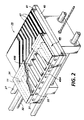
- Figure 2 is an enlarged schematic perspective view of the printhead of Figure 1;
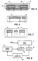
- Figure 3 is a cross-sectional side view of the printhead shown in Figure 2;
- Figure 4 is a plan view of the printhead shown in Figure 3;
- Figure 5 is an enlarged plan view of a second embodiment of the heater and thermistor layers;
- Figure 6 represents another embodiment showing different locations for the heater and temperature sensor components;
- Figure 7 is a still further embodiment showing alternative locations for the heater and temperature sensor components, and
- Figure 8 is an electrical control block diagram showing the feedback loop for controlling temperature of the printhead.
- A typical carriage type bubble jet
ink printing device 10 is shown in Fig. 1. A linear array of droplet-producing bubble jet channels is housed in theprinthead 11 of reciprocatingcarriage assembly 29.Droplets 12 are propelled to therecord medium 13 which is stepped by stepper motor 16 a preselected distance in the direction of arrow 14 each time the printing head traverses in one direction across the record medium in the direction ofarrow 15. The record medium, such as paper, is stored onsupply roll 17 and fed onto take-up roll 18 bystepper motor 16. - The
printhead 11 is fixedly mounted onsupport base 19 which is adapted for reciprocal movement on twoparallel guide rails 20. The printing head and base comprise thereciprocating carriage assembly 29 which is moved back and forth across the record medium in a direction parallel thereto and perpendicular to the direction in which the record medium is stepped. The reciprocal movement of the head is achieved by acable 21 and a pair of rotatable pulleys 22, one of which is powered by areversible motor 23. - The current pulses are applied to the individual bubble-generating resistors in each ink channel forming the array housed in the
printhead 11 overelectrical connections 24 fromcontroller 25. The current pulses which produce the ink droplets are generated in response to digital data signals received by the controller throughelectrode 26. The ink channels are maintained full during operation viahose 27 fromink supply 28. - Fig. 2 is an enlarged partially sectioned, perspective schematic of the
carriage assembly 29 shown in Fig. 1. Theprinthead 11 includessubstrate 41 containing theelectrical leads 47 and bubble-generating resistors 44 (shown in Fig. 3). According to the invention,heat sink substrate 42, incorporating the heater and thermistor as described in further detail below, is bonded to theprinthead substrate 41. Printhead 11 also includes thechannel plate 49 havingink channels 49A and manifold 49B. Although thechannel plate 49 is shown in twoseparate pieces ink channels 49A andink manifold 49B are formed in thechannel plate piece 31 having thenozzles 33 at the end of each ink channel opposite the end connecting themanifold 49B. Theink supply hose 27 is connected to the manifold 49B via apassageway 34 inchannel plate piece 31 shown in dashed line.Channel plate piece 32 is a flat member to coverchannel plate piece 31 and together form theink channel 49A andink manifold 49B as they are appropriately aligned and fixedly mounted onsubstrate 41. - Referring now to Figs. 3 and 4, Fig. 3 shows, (not to scale), a cross-sectional side view of
substrates Substrate 41 supports a plurality ofheating resistor elements 44 which are pulsed by signals sent alongelectrodes 47 to heat and expel ink fromnozzles 33.Substrate 41 is bonded toheat sink substrate 42 which, can be of copper or other heat conductive material.Substrate 42, in a preferred embodiment, has arecess 50 in the top surface. Anunderglaze dielectric layer 52 has been screened on to the bottom ofrecess 50. -
Recess 50, which can be formed by a machining operation, by coining, or by selective etching, is preferably from 0.05 to 0.175 mm deep.Resistive layers layer 52 by a thick-film screen-printing process. The leads to these layers (Figure 4) extend fromlayers recess 50 out into an exposed area for connection to a power source.Overglaze dielectric layer 58 covers layers 54 and 56 and their leads. Theprinthead substrate 41 is bonded to the three borders of the recessed area bydie bond layer 60.Bond layer 60 is assumed to be thermally conductive and may also be electrically conductive, if it is desired to hold the back of the printhead at the same potential as the substrate. This configuration allows good thermal contact between the printhead and the metal substrate in a limited, but critical, area near the front of the device, so that the most direct thermal conduction path from the heaters is maintained. This configuration also allows precise positioning of the printhead, with the metal surface as a reference. In a preferred embodimentunderglaze dielectric layer 52 is thicker thanoverglaze layer 58, placing the heater and sensor layers closer to the printhead than to the metal substrate. The temperature sensor 56 (thermistor) is made of a thick film material having a large temperature coefficient of resistance.Heater layer 54 may be a standard thick film resistor or, to conserve screen printing, it may be the same material aslayer 50. - Referring to Figure 4, there is shown a top plan view of the printhead of Figure 3 showing distances and widths from the edge of the array to the end of the recessed area. The letters refer to the following features: (a) is the size of the portion of
heat sink substrate 42 extending under the front of the printhead; (b) is the distance between the beginning of therecess 50 andheater 54; (c) is the width of theheater 54; (d) is the space betweenheater 54 andsensor 56; (e) is the width of thesensor 56, and (f) is the length of the printhead. In the preferred embodiment, the printhead width (a + b + c + d + e) is approximately 2.5 mm, while f is somewhat longer. If the space available is apportioned equally among a, b, c, d and e, then they will each be about 0.5 mm. - A second embodiment of the invention is shown in Figure 5. Here,
heater 54 andthermistor 56 are formed adjacent to each other and in the same plane to ease tolerances by omitting distances d and e (compared with the Figure 4 embodiment) so more space is available for distances a, b, and c. Other possible geometries, depending upon system requirements, are to form a long heater layer with a shorter thermistor at one end (Fig. 6), or to form a pair of larger heaters at each end with the smaller sensor positioned midway (Fig. 7). - A control circuit block diagram for the Figs. 3 to 7 embodiments is shown in Fig. 8. Outputs from
temperature sensor 56 are sent to acomparison circuit 60 where the signal is compared with a high-or low-level temperature reference. If the sensed printhead temperature is below the reference value, a signal is sent topower supply 62 turning heater power 'on'. If the temperature sensed is too high, heater power is turned 'off'. - While the invention has been described with reference to the structure disclosed, it is not confined to the specific details set forth. As one example, the
heater layer 54 and sensor layer 56 (Fig. 3) rather than being formed in parallel in the same horizontal plane, could be formed one above the other. Also, although a metal heat sink substrate was used in this preferred embodiment, other substrates may be used consistent with the deposition of thick film screened patterns thereon. Further, while a carriage was shown with a single printhead, the invention may be used in other configurations such as page-width printers. As a still further example, the recess may be omitted for certain applications, with the heater and sensor being formed on the surface of the printhead substrate still, however, separated therefrom by a dielectric layer.
Claims (10)
- A temperature control system for an ink jet printer which includes an ink jet printhead (41) bonded to an underlying heat sink substrate (42), the control system including means (56) for sensing the temperature of the printhead, heater means (54) thermally coupled to the printhead, the heat sink substrate (42) in thermal communication with the printhead, and control means (60) responsive to outputs from the temperature sensor and adapted to provide power selectively to the heater means, the temperature sensor and the heater means being resistive layers separated from the heat sink substrate and the printhead by layers of dielectric material (52, 58).
- The control system of claim 1, wherein the heat sink substrate (42) has in it a recess (50) in an area underlying the printhead, and wherein the temperature sensor and the heater means are formed in said recess.
- The control system of Claim 1, wherein the temperature sensor and the heater means are formed on the surface of the heat sink substrate.
- The control system of any preceding claim, wherein the resistive layers are formed by thick-film screening process.
- The control system of any preceding Claim, wherein the dielectric layer separating the resistive layers from the printhead is thinner than the dielectric layer between the same resistive layers and the heat sink substrate surface.
- The control system of any preceding Claim, wherein the heater resistive layer is adjacent to, and in the same plane as, the temperature sensor resistive layer.
- The control system of any preceding Claim, wherein the heater resistive layer is longer than the temperature sensor resistive layer.
- An ink jet printhead comprising a substrate (41) which incorporates ink heating resistors (44) adapted to heat ink supplied thereto by an ink channel and manifold assembly, and further comprising a heat sink substrate (42) bonded to the printhead substrate (41), the heat sink substrate incorporating a heater resistive layer (54) and a temperature sensor resistive layer (56) separated from printhead substrate and the heat sink substrate by layers of dielectric material (52, 58).
- The printhead of claim 8 wherein the resistive layers (54, 56) are formed by a thick-film screen printing process.
- The printhead of Claim 8 or 9, wherein the heater resistive layer is parallel to the temperature sensor resistive layer.
Applications Claiming Priority (2)
| Application Number | Priority Date | Filing Date | Title |
|---|---|---|---|
| US07/458,013 US4980702A (en) | 1989-12-28 | 1989-12-28 | Temperature control for an ink jet printhead |
| US458013 | 1989-12-28 |
Publications (3)
| Publication Number | Publication Date |
|---|---|
| EP0435565A2 EP0435565A2 (en) | 1991-07-03 |
| EP0435565A3 EP0435565A3 (en) | 1991-08-21 |
| EP0435565B1 true EP0435565B1 (en) | 1994-09-21 |
Family
ID=23819006
Family Applications (1)
| Application Number | Title | Priority Date | Filing Date |
|---|---|---|---|
| EP90313969A Expired - Lifetime EP0435565B1 (en) | 1989-12-28 | 1990-12-20 | Ink jet printer |
Country Status (5)
| Country | Link |
|---|---|
| US (1) | US4980702A (en) |
| EP (1) | EP0435565B1 (en) |
| JP (1) | JP3155548B2 (en) |
| CA (1) | CA2029528C (en) |
| DE (1) | DE69012770T2 (en) |
Families Citing this family (40)
| Publication number | Priority date | Publication date | Assignee | Title |
|---|---|---|---|---|
| EP0443722B1 (en) * | 1990-01-25 | 1996-05-22 | Canon Kabushiki Kaisha | Ink jet recording system |
| JP2815959B2 (en) * | 1990-02-19 | 1998-10-27 | キヤノン株式会社 | Liquid jet recording device |
| ATE311983T1 (en) * | 1990-02-26 | 2005-12-15 | Canon Kk | METHOD FOR LOCATING A TEMPERATURE SENSOR ON AN INKJET RECORDING HEAD SUBSTRATE |
| US5121130A (en) * | 1990-11-05 | 1992-06-09 | Xerox Corporation | Thermal ink jet printing apparatus |
| US5223853A (en) * | 1992-02-24 | 1993-06-29 | Xerox Corporation | Electronic spot size control in a thermal ink jet printer |
| US5321427A (en) * | 1992-06-03 | 1994-06-14 | Eastman Kodak Company | Print head modulator |
| JP3133825B2 (en) * | 1992-06-12 | 2001-02-13 | キヤノン株式会社 | Recording device |
| US5341162A (en) * | 1992-08-24 | 1994-08-23 | Xerox Corporation | Liquid deagassing apparatus |
| US5300968A (en) * | 1992-09-10 | 1994-04-05 | Xerox Corporation | Apparatus for stabilizing thermal ink jet printer spot size |
| DE69328603T2 (en) * | 1992-10-15 | 2001-01-11 | Canon Kk | Ink jet recording device |
| US5623297A (en) * | 1993-07-07 | 1997-04-22 | Intermec Corporation | Method and apparatus for controlling a thermal printhead |
| US5483265A (en) * | 1994-01-03 | 1996-01-09 | Xerox Corporation | Minimization of missing droplets in a thermal ink jet printer by drop volume control |
| US5497174A (en) * | 1994-03-11 | 1996-03-05 | Xerox Corporation | Voltage drop correction for ink jet printer |
| JPH08118641A (en) * | 1994-10-20 | 1996-05-14 | Canon Inc | Ink jet head, ink jet head cartridge, ink jet device and ink container for ink jet head cartridge into which ink is re-injected |
| US5585825A (en) * | 1994-11-25 | 1996-12-17 | Xerox Corporation | Ink jet printer having temperature sensor for replaceable printheads |
| US5686943A (en) * | 1994-11-25 | 1997-11-11 | Xerox Corporation | Ink jet printer having temperature sensor for periodic contact with printhead |
| DE19504175C2 (en) * | 1995-02-07 | 1998-06-04 | Siemens Ag | Device for metering and atomizing fluid, in particular fuel, in engine injection valves |
| JPH08276572A (en) * | 1995-04-07 | 1996-10-22 | Sharp Corp | Ink jet printer and adjustment thereof |
| US5797329A (en) * | 1995-05-16 | 1998-08-25 | Dataproducts Corporation | Hot melt ink printer and method printing |
| US5745130A (en) * | 1995-12-11 | 1998-04-28 | Xerox Corporation | System for sensing the temperature of a printhead in an ink jet printer |
| US5706041A (en) * | 1996-03-04 | 1998-01-06 | Xerox Corporation | Thermal ink-jet printhead with a suspended heating element in each ejector |
| JPH10774A (en) * | 1996-06-14 | 1998-01-06 | Canon Inc | Substrate for ink jet recording head and ink jet recording head equipped therewith |
| US5881451A (en) * | 1996-06-21 | 1999-03-16 | Xerox Corporation | Sensing the temperature of a printhead in an ink jet printer |
| AU1139100A (en) * | 1998-10-16 | 2000-05-08 | Silverbrook Research Pty Limited | Improvements relating to inkjet printers |
| US6328407B1 (en) | 1999-01-19 | 2001-12-11 | Xerox Corporation | Method and apparatus of prewarming a printhead using prepulses |
| US6357863B1 (en) | 1999-12-02 | 2002-03-19 | Lexmark International Inc. | Linear substrate heater for ink jet print head chip |
| US6427597B1 (en) | 2000-01-27 | 2002-08-06 | Patrice M. Aurenty | Method of controlling image resolution on a substrate |
| US6299273B1 (en) | 2000-07-14 | 2001-10-09 | Lexmark International, Inc. | Method and apparatus for thermal control of an ink jet printhead |
| US6601941B1 (en) | 2000-07-14 | 2003-08-05 | Christopher Dane Jones | Method and apparatus for predicting and limiting maximum printhead chip temperature in an ink jet printer |
| DE10036345B4 (en) * | 2000-07-26 | 2005-07-07 | Francotyp-Postalia Ag & Co. Kg | Arrangement and method for data tracking for warm-up cycles of inkjet printheads |
| KR100419227B1 (en) * | 2002-05-30 | 2004-02-21 | 삼성전자주식회사 | Device for preventing overheat of printer head |
| US6880911B2 (en) * | 2003-07-15 | 2005-04-19 | Toshiba Tec Kabushiki Kaisha | Ink jet head unit |
| US6928380B2 (en) * | 2003-10-30 | 2005-08-09 | International Business Machines Corporation | Thermal measurements of electronic devices during operation |
| US7296871B2 (en) * | 2004-12-29 | 2007-11-20 | Lexmark International, Inc. | Device and structure arrangements for integrated circuits and methods for analyzing the same |
| US7988260B2 (en) * | 2008-11-20 | 2011-08-02 | Canon Kabushiki Kaisha | Recording element substrate and recording head including recording element substrate |
| US8109591B2 (en) | 2009-01-23 | 2012-02-07 | Xerox Corporation | System and method for protecting a printer from an over-temperature condition in a printhead |
| JP6249682B2 (en) * | 2013-08-27 | 2017-12-20 | キヤノン株式会社 | Liquid discharge head substrate, liquid discharge head, and recording apparatus. |
| JP6113254B1 (en) * | 2015-11-26 | 2017-04-12 | 三菱電機株式会社 | Infrared light source |
| JP6971609B2 (en) * | 2017-04-04 | 2021-11-24 | キヤノン株式会社 | Recording device and recording method |
| CN113412193B (en) | 2019-02-06 | 2022-12-13 | 惠普发展公司,有限责任合伙企业 | Printing component and integrated circuit associated with replaceable printhead cartridge |
Family Cites Families (16)
| Publication number | Priority date | Publication date | Assignee | Title |
|---|---|---|---|---|
| DE2659398A1 (en) * | 1976-12-29 | 1978-07-06 | Siemens Ag | HEATING DEVICE FOR WRITING HEADS IN INK MOSAIC WRITING DEVICES |
| US4125845A (en) * | 1977-08-25 | 1978-11-14 | Silonics, Inc. | Ink jet print head pressure and temperature control circuits |
| CA1127227A (en) * | 1977-10-03 | 1982-07-06 | Ichiro Endo | Liquid jet recording process and apparatus therefor |
| JPS57145369A (en) * | 1981-03-03 | 1982-09-08 | Nec Corp | Integrated circuit device |
| JPS58160169A (en) * | 1982-03-18 | 1983-09-22 | Shinko Electric Co Ltd | Thermal printer |
| JPS58220757A (en) * | 1982-06-18 | 1983-12-22 | Canon Inc | Liquid jet recording head |
| JPS59145162A (en) * | 1983-02-08 | 1984-08-20 | Toppan Printing Co Ltd | Thermal head |
| JPS60116451A (en) * | 1983-11-30 | 1985-06-22 | Canon Inc | Liquid jet recording head |
| JPS60116452A (en) * | 1983-11-30 | 1985-06-22 | Canon Inc | Liquid jet recording head |
| US4532530A (en) * | 1984-03-09 | 1985-07-30 | Xerox Corporation | Bubble jet printing device |
| JPH0630929B2 (en) * | 1985-09-04 | 1994-04-27 | キヤノン株式会社 | Inkjet printer |
| US4636812A (en) * | 1985-10-24 | 1987-01-13 | Dynamics Research Corporation | Thermal print head temperature control |
| JPS6334144A (en) * | 1986-07-29 | 1988-02-13 | Canon Inc | Liquid jet recording head |
| US4791435A (en) * | 1987-07-23 | 1988-12-13 | Hewlett-Packard Company | Thermal inkjet printhead temperature control |
| US4831390A (en) * | 1988-01-15 | 1989-05-16 | Xerox Corporation | Bubble jet printing device with improved printhead heat control |
| US4899180A (en) * | 1988-04-29 | 1990-02-06 | Xerox Corporation | On chip heater element and temperature sensor |
-
1989
- 1989-12-28 US US07/458,013 patent/US4980702A/en not_active Expired - Lifetime
-
1990
- 1990-11-08 CA CA002029528A patent/CA2029528C/en not_active Expired - Lifetime
- 1990-11-30 JP JP34121390A patent/JP3155548B2/en not_active Expired - Lifetime
- 1990-12-20 DE DE69012770T patent/DE69012770T2/en not_active Expired - Lifetime
- 1990-12-20 EP EP90313969A patent/EP0435565B1/en not_active Expired - Lifetime
Also Published As
| Publication number | Publication date |
|---|---|
| EP0435565A3 (en) | 1991-08-21 |
| CA2029528A1 (en) | 1991-06-29 |
| DE69012770D1 (en) | 1994-10-27 |
| JP3155548B2 (en) | 2001-04-09 |
| DE69012770T2 (en) | 1995-04-13 |
| EP0435565A2 (en) | 1991-07-03 |
| JPH03203658A (en) | 1991-09-05 |
| CA2029528C (en) | 1992-09-29 |
| US4980702A (en) | 1990-12-25 |
Similar Documents
| Publication | Publication Date | Title |
|---|---|---|
| EP0435565B1 (en) | Ink jet printer | |
| EP0434367B1 (en) | Thermal ink jet printheads | |
| JP2832576B2 (en) | Temperature holding device and method | |
| JP2981018B2 (en) | Thermal ink jet printhead with droplet volume control and method of controlling the same | |
| US9862187B1 (en) | Inkjet printhead temperature sensing at multiple locations | |
| JP5213367B2 (en) | Inkjet recording head | |
| US4831390A (en) | Bubble jet printing device with improved printhead heat control | |
| US6871929B2 (en) | System and method for optimizing temperature operating ranges for a thermal inkjet printhead | |
| US7445315B2 (en) | Thin film and thick film heater and control architecture for a liquid drop ejector | |
| JPH07290695A (en) | Ink jet recorder and recording method | |
| EP1022139B1 (en) | Ink jet printers | |
| US20030081099A1 (en) | System and method for optimizing ink drying time through multiple spaced printheads | |
| JP4035940B2 (en) | Inkjet head, inkjet printer | |
| JPH06134993A (en) | Ink jet recorder | |
| EP0564742A2 (en) | Melt-on-demand solid ink thermal ink jet printhead | |
| JPH0332850A (en) | Ink jet head | |
| JPH04173152A (en) | Temperature control device of ink jet recording device | |
| JP4619881B2 (en) | Inkjet head, inkjet recording apparatus, and inkjet recording method | |
| JPH04358839A (en) | Ink jet printer | |
| JPH04250061A (en) | Ink jet print head | |
| JP2003246068A (en) | Inkjet head | |
| JPH11198375A (en) | Ink jet recording head and recorder | |
| JPH01294046A (en) | Liquid jet recording head | |
| JPH0392357A (en) | Ink amount detector | |
| JPH11254704A (en) | Liquid discharge head, head cartridge, and image-forming apparatus |
Legal Events
| Date | Code | Title | Description |
|---|---|---|---|
| PUAI | Public reference made under article 153(3) epc to a published international application that has entered the european phase |
Free format text: ORIGINAL CODE: 0009012 |
|
| AK | Designated contracting states |
Kind code of ref document: A2 Designated state(s): DE FR GB |
|
| PUAL | Search report despatched |
Free format text: ORIGINAL CODE: 0009013 |
|
| AK | Designated contracting states |
Kind code of ref document: A3 Designated state(s): DE FR GB |
|
| 17P | Request for examination filed |
Effective date: 19920124 |
|
| 17Q | First examination report despatched |
Effective date: 19931118 |
|
| GRAA | (expected) grant |
Free format text: ORIGINAL CODE: 0009210 |
|
| AK | Designated contracting states |
Kind code of ref document: B1 Designated state(s): DE FR GB |
|
| REF | Corresponds to: |
Ref document number: 69012770 Country of ref document: DE Date of ref document: 19941027 |
|
| ET | Fr: translation filed | ||
| PLBE | No opposition filed within time limit |
Free format text: ORIGINAL CODE: 0009261 |
|
| STAA | Information on the status of an ep patent application or granted ep patent |
Free format text: STATUS: NO OPPOSITION FILED WITHIN TIME LIMIT |
|
| 26N | No opposition filed | ||
| REG | Reference to a national code |
Ref country code: GB Ref legal event code: IF02 |
|
| PGFP | Annual fee paid to national office [announced via postgrant information from national office to epo] |
Ref country code: GB Payment date: 20091216 Year of fee payment: 20 Ref country code: FR Payment date: 20091221 Year of fee payment: 20 |
|
| PGFP | Annual fee paid to national office [announced via postgrant information from national office to epo] |
Ref country code: DE Payment date: 20091217 Year of fee payment: 20 |
|
| REG | Reference to a national code |
Ref country code: GB Ref legal event code: PE20 Expiry date: 20101219 |
|
| PG25 | Lapsed in a contracting state [announced via postgrant information from national office to epo] |
Ref country code: GB Free format text: LAPSE BECAUSE OF EXPIRATION OF PROTECTION Effective date: 20101219 |
|
| PG25 | Lapsed in a contracting state [announced via postgrant information from national office to epo] |
Ref country code: DE Free format text: LAPSE BECAUSE OF EXPIRATION OF PROTECTION Effective date: 20101220 |