EP0435577A2 - Method and apparatus for coating receptor substrates in an enclosed planetary array - Google Patents
Method and apparatus for coating receptor substrates in an enclosed planetary array Download PDFInfo
- Publication number
- EP0435577A2 EP0435577A2 EP90314010A EP90314010A EP0435577A2 EP 0435577 A2 EP0435577 A2 EP 0435577A2 EP 90314010 A EP90314010 A EP 90314010A EP 90314010 A EP90314010 A EP 90314010A EP 0435577 A2 EP0435577 A2 EP 0435577A2
- Authority
- EP
- European Patent Office
- Prior art keywords
- horizontal axis
- coating
- substrates
- chamber
- substrate
- Prior art date
- Legal status (The legal status is an assumption and is not a legal conclusion. Google has not performed a legal analysis and makes no representation as to the accuracy of the status listed.)
- Granted
Links
Images


Classifications
-
- B—PERFORMING OPERATIONS; TRANSPORTING
- B05—SPRAYING OR ATOMISING IN GENERAL; APPLYING FLUENT MATERIALS TO SURFACES, IN GENERAL
- B05B—SPRAYING APPARATUS; ATOMISING APPARATUS; NOZZLES
- B05B13/00—Machines or plants for applying liquids or other fluent materials to surfaces of objects or other work by spraying, not covered by groups B05B1/00 - B05B11/00
- B05B13/02—Means for supporting work; Arrangement or mounting of spray heads; Adaptation or arrangement of means for feeding work
- B05B13/0221—Means for supporting work; Arrangement or mounting of spray heads; Adaptation or arrangement of means for feeding work characterised by the means for moving or conveying the objects or other work, e.g. conveyor belts
- B05B13/0242—Means for supporting work; Arrangement or mounting of spray heads; Adaptation or arrangement of means for feeding work characterised by the means for moving or conveying the objects or other work, e.g. conveyor belts the objects being individually presented to the spray heads by a rotating element, e.g. turntable
-
- B—PERFORMING OPERATIONS; TRANSPORTING
- B05—SPRAYING OR ATOMISING IN GENERAL; APPLYING FLUENT MATERIALS TO SURFACES, IN GENERAL
- B05B—SPRAYING APPARATUS; ATOMISING APPARATUS; NOZZLES
- B05B3/00—Spraying or sprinkling apparatus with moving outlet elements or moving deflecting elements
- B05B3/02—Spraying or sprinkling apparatus with moving outlet elements or moving deflecting elements with rotating elements
- B05B3/10—Spraying or sprinkling apparatus with moving outlet elements or moving deflecting elements with rotating elements discharging over substantially the whole periphery of the rotating member, i.e. the spraying being effected by centrifugal forces
- B05B3/1064—Spraying or sprinkling apparatus with moving outlet elements or moving deflecting elements with rotating elements discharging over substantially the whole periphery of the rotating member, i.e. the spraying being effected by centrifugal forces the liquid or other fluent material to be sprayed being axially supplied to the rotating member through a hollow rotating shaft
-
- B—PERFORMING OPERATIONS; TRANSPORTING
- B05—SPRAYING OR ATOMISING IN GENERAL; APPLYING FLUENT MATERIALS TO SURFACES, IN GENERAL
- B05C—APPARATUS FOR APPLYING FLUENT MATERIALS TO SURFACES, IN GENERAL
- B05C9/00—Apparatus or plant for applying liquid or other fluent material to surfaces by means not covered by any preceding group, or in which the means of applying the liquid or other fluent material is not important
- B05C9/08—Apparatus or plant for applying liquid or other fluent material to surfaces by means not covered by any preceding group, or in which the means of applying the liquid or other fluent material is not important for applying liquid or other fluent material and performing an auxiliary operation
- B05C9/14—Apparatus or plant for applying liquid or other fluent material to surfaces by means not covered by any preceding group, or in which the means of applying the liquid or other fluent material is not important for applying liquid or other fluent material and performing an auxiliary operation the auxiliary operation involving heating or cooling
-
- F—MECHANICAL ENGINEERING; LIGHTING; HEATING; WEAPONS; BLASTING
- F26—DRYING
- F26B—DRYING SOLID MATERIALS OR OBJECTS BY REMOVING LIQUID THEREFROM
- F26B15/00—Machines or apparatus for drying objects with progressive movement; Machines or apparatus with progressive movement for drying batches of material in compact form
-
- H—ELECTRICITY
- H01—ELECTRIC ELEMENTS
- H01L—SEMICONDUCTOR DEVICES NOT COVERED BY CLASS H10
- H01L21/00—Processes or apparatus adapted for the manufacture or treatment of semiconductor or solid state devices or of parts thereof
- H01L21/67—Apparatus specially adapted for handling semiconductor or electric solid state devices during manufacture or treatment thereof; Apparatus specially adapted for handling wafers during manufacture or treatment of semiconductor or electric solid state devices or components ; Apparatus not specifically provided for elsewhere
- H01L21/67005—Apparatus not specifically provided for elsewhere
- H01L21/67011—Apparatus for manufacture or treatment
- H01L21/67017—Apparatus for fluid treatment
- H01L21/67028—Apparatus for fluid treatment for cleaning followed by drying, rinsing, stripping, blasting or the like
-
- H—ELECTRICITY
- H01—ELECTRIC ELEMENTS
- H01L—SEMICONDUCTOR DEVICES NOT COVERED BY CLASS H10
- H01L21/00—Processes or apparatus adapted for the manufacture or treatment of semiconductor or solid state devices or of parts thereof
- H01L21/67—Apparatus specially adapted for handling semiconductor or electric solid state devices during manufacture or treatment thereof; Apparatus specially adapted for handling wafers during manufacture or treatment of semiconductor or electric solid state devices or components ; Apparatus not specifically provided for elsewhere
- H01L21/67005—Apparatus not specifically provided for elsewhere
- H01L21/67011—Apparatus for manufacture or treatment
- H01L21/67155—Apparatus for manufacturing or treating in a plurality of work-stations
- H01L21/6719—Apparatus for manufacturing or treating in a plurality of work-stations characterized by the construction of the processing chambers, e.g. modular processing chambers
-
- H—ELECTRICITY
- H01—ELECTRIC ELEMENTS
- H01L—SEMICONDUCTOR DEVICES NOT COVERED BY CLASS H10
- H01L21/00—Processes or apparatus adapted for the manufacture or treatment of semiconductor or solid state devices or of parts thereof
- H01L21/67—Apparatus specially adapted for handling semiconductor or electric solid state devices during manufacture or treatment thereof; Apparatus specially adapted for handling wafers during manufacture or treatment of semiconductor or electric solid state devices or components ; Apparatus not specifically provided for elsewhere
- H01L21/67005—Apparatus not specifically provided for elsewhere
- H01L21/67011—Apparatus for manufacture or treatment
- H01L21/67155—Apparatus for manufacturing or treating in a plurality of work-stations
- H01L21/67196—Apparatus for manufacturing or treating in a plurality of work-stations characterized by the construction of the transfer chamber
-
- H—ELECTRICITY
- H01—ELECTRIC ELEMENTS
- H01L—SEMICONDUCTOR DEVICES NOT COVERED BY CLASS H10
- H01L21/00—Processes or apparatus adapted for the manufacture or treatment of semiconductor or solid state devices or of parts thereof
- H01L21/67—Apparatus specially adapted for handling semiconductor or electric solid state devices during manufacture or treatment thereof; Apparatus specially adapted for handling wafers during manufacture or treatment of semiconductor or electric solid state devices or components ; Apparatus not specifically provided for elsewhere
- H01L21/67005—Apparatus not specifically provided for elsewhere
- H01L21/67011—Apparatus for manufacture or treatment
- H01L21/67155—Apparatus for manufacturing or treating in a plurality of work-stations
- H01L21/67236—Apparatus for manufacturing or treating in a plurality of work-stations the substrates being processed being not semiconductor wafers, e.g. leadframes or chips
-
- B—PERFORMING OPERATIONS; TRANSPORTING
- B05—SPRAYING OR ATOMISING IN GENERAL; APPLYING FLUENT MATERIALS TO SURFACES, IN GENERAL
- B05B—SPRAYING APPARATUS; ATOMISING APPARATUS; NOZZLES
- B05B3/00—Spraying or sprinkling apparatus with moving outlet elements or moving deflecting elements
- B05B3/001—Spraying or sprinkling apparatus with moving outlet elements or moving deflecting elements incorporating means for heating or cooling, e.g. the material to be sprayed
Definitions
- the invention relates to a method and apparatus for coating drum and flexible belt charge receptors for photocopiers.
- a photoreceptor is a cylindrical or belt-like substrate used in a xerographic apparatus.
- the photoreceptor substrate is coated with one or more layers of a photoconductive material, i.e., a material whose electrical conductivity changes upon illumination.
- a photoconductive material i.e., a material whose electrical conductivity changes upon illumination.
- an electrical potential is applied across the photoconductive layer and then exposed to light from an image.
- the electrical potential of the photoconductive layer decays at the portions irradiated by the light from the image, leaving a distribution of electrostatic charge corresponding to the dark areas of the projected image
- the electrostatic latent image is made visible by development with a suitable powder. Better control of the coating quality yields better imaging performance.
- One method of coating substrates is to dip the substrate in a bath of the coating material.
- This method is disadvantageous because it usually results in a non- uniform coating.
- the coating thickness tends to "thin” or decrease at the top of the substrate and "slump" or increase at the base of the substrate due to gravity induced flow of the coating material as the substrate is lifted from the bath. Thickness variations also occur even when the photoreceptor is oriented horizontally and dipped into the bath due to the formation of a meniscus as the substrate is removed from the bath. This variation in coating thickness causes variations in the performance of the photoreceptor.
- the dipping process requires additional processing controls because the bath must be constantly maintained in a state suitable for coating.
- the bath increases the size of the entire processing apparatus and is not readily adaptable to rapid changes in coating formulations. Further, changes in coating formulations are inhibited due to incompatibilities between formulations for successive coatings or layers. It is also difficult to incorporate cleaning and curing operations that are compatible with the dipping process for efficient modular operation as a manufacturing process.
- an air assisted automatic spray gun uses high velocity air to atomize the coating formulation which is sprayed onto a substrate. Due to high mass transfer rates intrinsic to the use of atomizing air, this method entails considerable evaporative loss of solvent from the spray droplets and requires the use of slow evaporating solvents to prevent excessive solvent loss before the droplets arrive at the substrate. It is difficult to use this method in a sealed environment, and thus difficult to control the solvent humidity surrounding the substrates prior to, during, or after the coating process. In addition, the air atomized spray method creates a considerable amount of overspray which results in higher material usage. Air spray guns also are less advantageous for batch processing of a number of substrates.
- an apparatus for coating cylindrical or belt- like substrates comprising: a coating chamber defining a central horizontal axis; a support structure selectively receivable within the coating chamber for supporting at least one substrate along a horizontal axis radially offset from and parallel to the central horizontal axis, and for rotating said at least one substrate about its offset horizontal axis; applicator means supported in the coating chamber along the central horizontal axis for spraying a coating formulation radially outward onto said at least one substrate; and means for reciprocating said applicator means along said central horizontal axis while rotating said at least one substrate about the offset horizontal axis.
- the invention also provides a method for coating cylindrical and belt- like substrates comprising the steps of: supporting a plurality of substrates in a planetary array about a central horizontal axis of a sealed chamber, each substrate defining an offset horizontal axis radially spaced from and parallel to the central horizontal axis; applying a coating formulation from an applicator located along the central horizontal axis, the applicator applying the coating solution radially outward onto the substrates ; and reciprocating the applicator along the central horizontal axis while rotating the substrates about each offset horizontal axis.
- the invention provides a method or apparatus which permits batch processing of a plurality of substrates in compatible cleaning, coating and curing operations. It has the advantage that it provides an apparatus or method which obtains high quality coatings of uniform thickness.
- the apparatus is modular and occupies a relatively small area per unit of production. It is automatic and adaptable to different coating material formulations and substrates of differing diameters.
- the apparatus operates in a sealed environment in which solvent humidity can be controlled.
- the invention will be described in relation to fabrication of cylindrical and belt-like substrates, and particularly rigid cylindrical and flexible belt photoreceptor substrates for photocopiers.
- the invention is applicable to other coated substrates and/or coating processes.
- the overall apparatus and process for fabricating substrates includes a carousel 10 rotatable to several different stations surrounding the carousel, namely a substrate loading/unloading station 100, a cleaning station 200, a coating station 300, and a curing or drying station 400. All the stations 100, 200, 300, 400 and the carousel 10 are preferably located within a class 100 or better clean area 15, which minimizes coating defects by eliminating human interaction with the substrate and shortening the exposure time to airborne contaminants.
- the carousel 10 includes a horizontal platform 12 rotatable about a vertical axis V in either the clockwise or counterclockwise direction.
- the carousel is rotated by any conventional mechanism under the control of an operator and/or computer program.
- the carousel 10 includes a support structure 14 preferably extending vertically from the platform 12 in a plane parallel to the vertical axis V about which the carousel 10 rotates.
- the support structure 14 preferably reciprocates along the platform 12 in a horizontal direction (represented by arrow AA) toward and away from the station facing the support structure, although it also is possible for the stations to reciprocate toward and away from the support structure.
- the reciprocation of the support structure or station is accomplished by any conventional mechanism under the control of the operator and/or computer program.
- the support structure 14 includes a planetary array of support arms 16, each defining an offset horizontal axis h radially spaced from a central horizontal axis H of the support structure 14.
- Each support arm 16 is capable of carrying at least one substrate 18 (and preferably two substrates) so that the support structure 14 provides a planetary arrangement of substrates 18, each substrate being parallel to but radially spaced from the central horizontal axis H.
- the support arms are located in an annular array at equal radii relative to the central horizontal axis H so that the substrates are symmetrically positioned relative to the horizontal axis H.
- the support structure 14 carries a mechanism for rotating each support arm 16 about its offset horizontal axis h so that each substrate 18 in the planetary arrangement of substrates rotates about its offset horizontal axis h while being secured in a position parallel to but radially spaced from the central horizontal axis H.
- the support structure 14 can include any mechanism for rotating the support arm 16 and securing a substrate along the horizontal axis h , such as an interior rod-like structure, a rotatable cap or collet structure grasping the exterior surface of an end of the substrate, or a rotatable interior expanding structure insertable into the substrate for grasping the interior surface
- the substrates illustrates in Figure 2 can all have the same diameter (e.g., 84 mm)
- the support arms 16 are capable of supporting substrates of different diameters (e.g., 30 to 300 mm).
- the planetary arrangement of substrates 18 on the support structure 14 permits a large number of substrates to be processed simultaneously thereby increasing the throughput of the process and decreasing manufacturing costs.
- Each support arm 16 can carry multiple substrates and simple adjustments and/or modifications permit pro- cessing of substrates of varying diameters.
- the coating and curing stations described below can perform their operations from the central axis H radially outward while each substrate rotates about its offset axis h , so that each substrate is processed in an equal manner due to the radial symmetry thus ensuring uniformity and versatility in processing.
- the carousel 10 rotates about the vertical axis to position the planetary array of substrates before any one station 100, 200, 300, 400.
- the support structure reciprocates in the horizontal direction relative to the desired station to insert the planetary array of substrates 18 into the station.
- the support structure 14 preferably includes a sealing mechanism 20 about its periphery so that the support structure 14 functions as a closure member for sealing the chamber with the substrates located therein.
- the substrates are then processed within the sealed chamber, with each substrate rotating about its offset horizontal axis h. Once processed, the support structure 14 recedes from that station and the carousel 10 rotates to position the array of substrates for insertion into the next processing station.
- the individual stations for the fabrication process preferably are arranged in a symmetrical manner around the carousel 10.
- the basic processing steps are described below:
- the first operation is substrate loading in a loading/unloading station 100.
- Uncoated charge receptor substrates are loaded onto each support arm 16 of the support structure 14, either manually or via a programmed robot arm.
- Each substrate 18 is loaded onto and secured by Its support arm 16 along the offset horizontal axis h , which is then maintained parallel to and radially spaced from the central horizontal axis H.
- Substrate cleaning is the second operation performed at the cleaning station 200.
- the carousel 10 first rotates clockwise in Fig. 1, preferably 90°, to position the support structure 14 in front of the cleaning station 200 which includes a cleaning chamber 210 having a central horizontal axis colinear with the central horizontal axis H of the support structure 14.
- the support structure 14 then reciprocates toward the cleaning chamber 210 to insert the planetary array of substrates 18 into the chamber 210.
- the sealing mechanism 20 seals the chamber 210 with the substrates loaded therein.
- the substrates 18 are cleansed by any suitable mechanism such as liquid detergents, freon, or ozone with simultaneous exposure to ultraviolet light.
- the substrates 18 are rotated on their support arms 16 about their offset horizontal axis h during the cleaning operation so that each substrate is cleaned uniformly over its entire surface.
- the substrates preferably rotate during the cleaning operation at about 30-200 RPM.
- the atmosphere in the cleaning chamber is then exhausted and the substrates are withdrawn from the chamber 210 by reverse reciprocation of the support structure 14.
- the substrates are cleaned by exposure to a high pressure spray of a solvent based cleanser, such as a freon or detergent based solvent.
- a solvent based cleanser such as a freon or detergent based solvent.
- the spray preferably emanates from a central conduit 240 located along the central horizontal axis H of the cleaning chamber 210, but other cleansing structures are possible including dedicated nozzles, i.e., a structure wherein each nozzle in an array of nozzles is directed to a particular substrate.
- the central conduit 240 can have a series of nozzles 250 located therein for distributing the cleanser radially outward through all the nozzles simultaneously.
- the central conduit 240 can enclose a reciprocating outlet 260 (Fig.
- the reciprocating outlet can be moved by any conventional mechanism under a programmed control to ensure adequate spray through the outlets 250.
- the spray from the central conduit 240 emanates radially outward, as the substrates 16 are rotating about their offset horizontal axis h , thus optimizing the coverage of all substrates with regard to angular impingement, spray pressure and distance from the spray nozzles.
- the flowrate of the cleanser and the time of spraying within the cleansing chamber are variable depending on the cleanser material and substrate to be cleaned.
- the cleansing chamber 210 can also be equipped with an air supply mechanism (as part of or separate from the central conduit 240) to supply air at sufficient temperatures to equilibrate the substrates to the required process temperature (to counteract evaporative cooling) and to reduce vapor emissions from the chamber.
- the support structure 14 retracts the substrate array 18 from the cleaning chamber 210 and moves the array to the coating station for further processing.
- the third operation is substrate coating at the coating station 300.
- the carousel rotates clockwise preferably another 90° to position the planetary array of cleaned substrates 18 before the coating station 300 which includes a coating chamber 310 defining a central horizontal axis colinear with the central horizontal axis H of the support structure 14.
- the support structure 14 then advances to insert the planetary array into the coating chamber 310 with the sealing mechanism 20 sealing the chamber.
- the substrates are then coated (via mechanisms described below) with a coating solution containing one or more materials useful in electrophotography. When the coating process is complete, the substrates are withdrawn from the coating chamber 310 by reverse reciprocation of the support structure 14.
- an electrostatic rotary atomizer 320 (Figs. 5A and 5B) which is a commercially available device, such as the DEVlLBLISS AEROBELL and the GRACO CA 1000, CT 4000 or Resistive Micro-Bell rotary atomizers.
- an electrostatic rotary atomizer 320 includes two parts: an atomizer housing 322 enclosing rotary turbine blades (not shown) and feed conduits (not shown) for a coating solution and a solvent; and a rotating bell or cap 324 spaced from one end of the atomizer housing 322.
- the coating solution and solvent are expelled through injection ports at the end of the atomizer housing 322 against the rotating bell or cap 324, which atomizes the coating solution and solvent and directs a charged spray radially outward from the rotary atomizer.
- the atomizer 320 can be reciprocated along the axis of the substrate to be coated.
- Conventional mechanisms are available for rotating and reciprocating the atomizer 320.
- the planetary arrangement of horizontal substrates surrounding the electrostatic rotary atomizer 320 are thus positioned in a symmetrical configuration with respect to the spray cloud produced by the rotary atomizer 320. Each substrate thus receives a uniform coating.
- a fast evaporating solvent may first be sprayed into the sealed coating chamber (via a mechanism described below) to obtain a preset vapor pressure of up to saturation of the air within the chamber.
- the coating solution containing the same fast evaporating solvent is then sprayed using the electrostatic rotary atomizer 320 while rotating the substrates and recipro- cating the atomizer back and forth along the central axis H in the center of the planetary configuration.
- the reciprocating rotary atomizer centrally located in the planetary array of rotating substrates has several advantages. In addition to applying a uniform coating to the substrate, the atomization and curing processes are separated allowing each process to be better defined and controlled. In addition, fast evaporating solvents may be used to reduce the drying requirements by reducing the drying time and the energy required for drying.
- the atomizer centrally located in the sealed chamber of the planetary array of rotating horizontal substrate also provides for a narrow distribution of small droplets which allows for a uniform thin coating in all substrates without typical coating defects such as "orange peel" effects.
- the coating formulation of a coating solution and solvent are expelled at about 50-400 cc/minute at an atomizer speed of 15,000-60,000RPM, a reciprocation speed of 5-40 mm/sec, and an electrostatic voltage 30-150 kv (plus or minus charge).
- the coating formulation preferably has a concentration of .5- 50% solid and a viscosity of 1-100 centipoise.
- the substrates are rotating at about 20-100 RPM in a coating chamber having a temperature of 0 - 30°C.
- the coating formulation can include coating materials such as nylon, polyester or polycarbonate; and solvents such as methylene chloride, toluene, methanol, or ethanol. All the parameters discussed above may vary depending on the coating solution, solvent and desired type of coating.
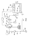
- the coating chamber is sealed and provided with a solvent vapor control mechanism 330 (Fig. 6) to limit and control the rate of solvent evaporation during droplet flight, film formation and film solidification.
- the solvent vapor control mechanism 330 introduces a controlled amount of solvent vapor into the coating chamber prior to film deposition, maintains the solvent concentration in the chamber gas near saturation during film leveling, and limits the rate of solvent vapor removal during the initial stages of solvent evaporation to prevent hydrodynamic instabilities which could cause patterning or pockets (i.e., an orange-peel effect) in the dried film.
- the solvent vapor control mechanism 330 can supply solvent either directly through the electrostatic rotary atomizer 320 or through a separate inlet device for introducing solvent into the coating chamber 310.
- the following description will focus on a solvent vapor control mechanism which introduces solvent into the coating chamber 310 through a separate inlet device, although those skilled in the art recognize that the mechanism 330 can be adapted to introduce solvent through the atomizer 320.
- the coating chamber 310 (which preferably includes an insulation jacket 315) communicates with a conduit mechanism having an inlet line 340, and outlet line 342 and a recirculation line 344 providing communication between the inlet and outlet lines 340, 342.
- the inlet line 340 may include a nitrogen gas supply 346 for purging the chamber to reduce the oxygen concentration in the chamber in the event flammable solvents are used for the film deposition.
- Oxygen sensors 348 can be located in the chamber 310 and/or outlet line 342.
- nitrogen valve 350 and damper B are opened to supply nitrogen gas through the inlet line 340 into the chamber 310 to dilute the air within the chamber (supplied via damper A and the clean air supply 351) to a point where the concentration of oxygen is low enough (less than approximately 5%) so that combustion cannot be supported. Nitrogen is exhausted by opening dampers C and D and activating the exhaust blower 352. If flammable solvents are not used, the nitrogen purge is unnecessary.
- the dampers are repositioned to open dampers A, B, C, E and F and close damper D while the recirculation blower 354 is started so that gas from the chamber 310 is continuously recirculated through the solvent from solvent supply 357 vapor introduction plenum 356 in the inlet line 340.
- a controlled amount of solvent from solvent supply 357 (which is the same solvent in the coating formulation to be deposited) is added to the gas stream, and the temperature of the gas is controlled to create a desired relative solvent humidity. For example, if a chamber atmosphere of about 90% relative solvent humidity is desired, the solvent vapor introduction plenum is operated as follows:
- the dampers A-F are closed and the substrates are coated by the rotary atomizer 320 using a solvent based coating formulation using the same solvent as the solvent in the introduction plenum 356.
- An improved film quality is obtained because solvent evaporation during droplet flight and film leveling is minimized due to the presence of the solvent previously introduced into the chamber.
- the opportunity to apply coatings formulated with more volatile solvent offers improved throughput due to shortened drying times and increased cost savings due to lower drying temperatures.
- solvent evaporation is so fast that drying between layer applications may be eliminated.
- a subsequent coating layer can be immediately applied as soon as the film is in a sufficiently inviscid state.
- the solvent vapor is removed by controlling evaporation of the solvent from the film.
- the controlled evaporation is accomplished by resuming recirculation of the gas mixture through the chamber by opening dampers A, B, C, E and F and activating the recirculation blower 354.
- the solvent saturated gas flows through the solvent vapor introduction plenum 356 with only the chiller coil 362 operating which condenses the solvent out of the gas stream.
- the liquid solvent draining from the chiller and demister is recovered in a containment vessel 370.
- the rate of solvent removal may be controlled by either controlling the gas flow rate (via the blowers and dampers) and/or controlling the chiller temperature.
- the second heater 364 reheats the incoming gas stream.
- the gas recirculation is stopped and the support structure 14 retracts to remove the substrate 18 from the coating chamber.
- a subsequent coating layer may be applied as noted above.
- the coating chamber may be further modified for fabrication of hybrid photoreceptor devices.
- the chamber could be fabricated with stronger walls, vacuum service lines 380 (Fig. 5A) and vacuum tight seals so that vacuum deposition of thin films could be performed in the chamber as well as solvent based rotary atomization spray coating.
- This dual capability permits production of different kinds of photoreceptors having a vacuum coating and an atomizer applied coating using the same apparatus thus further increasing the versatility and efficiency of the process.
- the fourth operation is film curing or drying at the curing station 400.
- the carousel 10 rotates clockwise preferably another 90° to position the planetary array of coating substrates 18 in front of the curing chamber 410 which also defines a central horizontal axis co-linear with the central horizontal axis H of the support structure 14.
- the support structure 14 is then advanced to insert the planetary array of substrates 18 into the chamber 410. If there is solvent present in the coating film, it is removed by exposure to high velocity heated air (e.g., 113m3 min ⁇ 1 at 60-140°C for 1-5 minutes). If the film is photochemically reactive, the film is cured by exposure to ultraviolet light. When curing is complete, the substrates are cooled by chilled air (if necessary) and then withdrawn from the chamber. If a multilayered film structure is desired, operations 3 and 4 are repeated as necessary with the carousel 10 cycling between the coating and curing chambers 310,410.
- the curing chamber includes a curing mechanism to remove solvent from the freshly coated film on the substrate by exposing the substrate to a heated stream of high velocity air as the substrate rotates.
- the drying mechanism includes ( Figures 7A and 7B) a perforated air supply plenum 420 communicating with the source of temperature controlled air.
- the plenum 420 is located along the horizontal axis H of the chamber 410 so as to be surrounded by the planetary arrangement of substrates 18. Clean heated air flows radially outward through the perforated plenum 420 at high velocity, and impinges on the rotating surfaces of the coated substrates (rotating at about 20-100 RPM).
- the high velocity air minimizes the boundary layer, and the resultant high heat and mass transfer rates permit rapid solvent removal.
- FIG. 7A and 7B Although a perforated plenum wall is shown in Figures 7A and 7B, other configurations such as an air-fed cylinder 425 located along the central axis H and having nozzles 430 (Fig. 7C) aligned axially with the individual substrates may be used to import high velocity air to the substrate rotating at about 20-100 RPM.
- the curing chamber may include an array of dedicated nozzles, each being directed to expel air toward a particular substrate.
- the air supply temperature and flow rate are optimally controlled to minimize curing time without comprising coated surface quality and imaging performance.
- the air supply temperature is lowered to below ambient temperature to rapidly cool the substrate to ambient temperature.
- the carousel 10 then returns the planetary array of substrates 18 to the coating chamber 310 for a further layer application, or to the load/unload station 100 if fabrication is complete.
- the curing structure is compatible with the processing of substrates in a planetary configuration.
- the curing structure is versatile since the outward radial flow from the plenum to the substrate permits a single curing chamber to be used with batches of coated substrates of differing diameters.
- the planetary arrangement of substrates with the central curing structure provides a synthetical system which reduces drying times and reduces temperature variations in the substrate.
- the curing station is capable of curing both substrates coated with a solvent based film by exposure to high velocity heated air, and substrates coated with photoreactive polymer films by exposure to ultraviolet light.
- the curing chamber 410 is equipped with an annular ultraviolet light source 450 ( Figure 8) having an axis co-linear with the central axis H.
- the light 450 is mounted within a concentric reflector 460 to provide a band b of light which radiates with equal intensity 360° around the reflector 460.
- the light source 450 and concentric reflector 460 are mounted on a carriage 470 which reciprocates along the central horizontal axis H as each substrate 18 rotates about the offset horizontal axis h.
- a band b of ultraviolet light radiates outward and moves axially from end to end of the substrate 18 so that each substrate "sees” or is exposed to the band b of ultraviolet light several centimeters wide scanning along the axis of the substrate.
- Each exposure polymerizes the photochemically reactive coating on the substrate to produce a solid uniformly cured film.
- Optimum performance is obtained by matching reciprocation speed, rotational speed of the substrates, photochemistry of the film, intensity in wavelength of the ultraviolet lamp and width of the exposure band.
- the fifth operation is substrate unloading, preferably at the loading/unloading station 100.
- the carousel rotates clockwise preferably another 90° to the position occupied in Operation 1 where the coated and cured substrates are unloaded from the support structure manually or under programmed control.
- the finished charge receptors may then be inspected and packaged as desired.
- each station is compatible for batch processing of substrates arranged in a planetary array which permits a large number of substrates to be processed simultaneously and uniformly.
- the planetary substrate array also permits each substrate to be processed in an equal manner due to the radial symmetry.
Abstract
Description
- The invention relates to a method and apparatus for coating drum and flexible belt charge receptors for photocopiers.
- A photoreceptor is a cylindrical or belt-like substrate used in a xerographic apparatus. The photoreceptor substrate is coated with one or more layers of a photoconductive material, i.e., a material whose electrical conductivity changes upon illumination. In xerographic use, an electrical potential is applied across the photoconductive layer and then exposed to light from an image. The electrical potential of the photoconductive layer decays at the portions irradiated by the light from the image, leaving a distribution of electrostatic charge corresponding to the dark areas of the projected image The electrostatic latent image is made visible by development with a suitable powder. Better control of the coating quality yields better imaging performance.
- One method of coating substrates is to dip the substrate in a bath of the coating material. This method is disadvantageous because it usually results in a non- uniform coating. In particular, when the substrate is oriented vertically and dipped into a bath, the coating thickness tends to "thin" or decrease at the top of the substrate and "slump" or increase at the base of the substrate due to gravity induced flow of the coating material as the substrate is lifted from the bath. Thickness variations also occur even when the photoreceptor is oriented horizontally and dipped into the bath due to the formation of a meniscus as the substrate is removed from the bath. This variation in coating thickness causes variations in the performance of the photoreceptor. In addition, the dipping process requires additional processing controls because the bath must be constantly maintained in a state suitable for coating. The bath increases the size of the entire processing apparatus and is not readily adaptable to rapid changes in coating formulations. Further, changes in coating formulations are inhibited due to incompatibilities between formulations for successive coatings or layers. It is also difficult to incorporate cleaning and curing operations that are compatible with the dipping process for efficient modular operation as a manufacturing process.
- In another method, an air assisted automatic spray gun uses high velocity air to atomize the coating formulation which is sprayed onto a substrate. Due to high mass transfer rates intrinsic to the use of atomizing air, this method entails considerable evaporative loss of solvent from the spray droplets and requires the use of slow evaporating solvents to prevent excessive solvent loss before the droplets arrive at the substrate. It is difficult to use this method in a sealed environment, and thus difficult to control the solvent humidity surrounding the substrates prior to, during, or after the coating process. In addition, the air atomized spray method creates a considerable amount of overspray which results in higher material usage. Air spray guns also are less advantageous for batch processing of a number of substrates.
- It is thus an object of the invention to obviate the foregoing drawbacks of the prior art by providing a more efficient apparatus and process for fabricating rigid cylindrical or flexible belt photoreceptors.
- According to the invention, there is provided an apparatus for coating cylindrical or belt- like substrates comprising:
a coating chamber defining a central horizontal axis;
a support structure selectively receivable within the coating chamber for supporting at least one substrate along a horizontal axis radially offset from and parallel to the central horizontal axis, and for rotating said at least one substrate about its offset horizontal axis;
applicator means supported in the coating chamber along the central horizontal axis for spraying a coating formulation radially outward onto said at least one substrate;
and means for reciprocating said applicator means along said central horizontal axis while rotating said at least one substrate about the offset horizontal axis. - The invention also provides a method for coating cylindrical and belt- like substrates comprising the steps of:
supporting a plurality of substrates in a planetary array about a central horizontal axis of a sealed chamber, each substrate defining an offset horizontal axis radially spaced from and parallel to the central horizontal axis;
applying a coating formulation from an applicator located along the central horizontal axis, the applicator applying the coating solution radially outward onto the substrates ; and
reciprocating the applicator along the central horizontal axis while rotating the substrates about each offset horizontal axis. - The invention provides a method or apparatus which permits batch processing of a plurality of substrates in compatible cleaning, coating and curing operations. It has the advantage that it provides an apparatus or method which obtains high quality coatings of uniform thickness.
- The apparatus is modular and occupies a relatively small area per unit of production. It is automatic and adaptable to different coating material formulations and substrates of differing diameters. The apparatus operates in a sealed environment in which solvent humidity can be controlled.
- The invention will be described in detail herein with reference to the following Figures in which like reference numerals denote like elements and wherein:
- Figure 1 is an overall schematic view of the apparatus and process in accordance with the present invention for fabricating rigid cylindrical and flexible belt photoreceptor substrates;
- Figure 2 is a schematic plan view of a carousel and substrate supporting structure;
- Figure 3 is a schematic perspective view of the substrate supporting structure;
- Figure 4A is a schematic top cross-sectional view of the cleaning chamber with the substrates located in the chamber;
- Figure 4B is a schematic side cross-sectional view of the cleaning chamber taken along the line W-W of Fig. 4A;
- Figure 4C is a schematic cross-sectional side view of an alternative nozzle structure for the cleaning chamber of Figures 4A and 4B;
- Figure 5A is a schematic cross-sectional top view of the coating chamber;
- Figure 5B is a schematic cross-sectional side view of the coating chamber taken along the lines X-X of Fig. 5A;
- Figure 6 is a schematic view of a solvent vapor control mechanism;
- Figure 7A is a schematic cross-sectional top view of a curing chamber;
- Figure 7B is a schematic cross-sectional side view of the curing chamber taken along the lines Y-Y of Fig. 7A;
- Figure 7C is a schematic cross-sectional side view of an alternative nozzle structure for the curing chamber of Figure 7A;
- Figure 8A is a schematic cross-sectional top view of another embodiment of the curing chamber; and
- Figure 8B is a schematic cross-sectional side view of the curing chamber taken along the lines Z-Z of Fig. 8A.
- The invention will be described in relation to fabrication of cylindrical and belt-like substrates, and particularly rigid cylindrical and flexible belt photoreceptor substrates for photocopiers. The invention, however, is applicable to other coated substrates and/or coating processes.
- As illustrated in Figure 1, the overall apparatus and process for fabricating substrates includes a carousel 10 rotatable to several different stations surrounding the carousel, namely a substrate loading/
unloading station 100, acleaning station 200, acoating station 300, and a curing ordrying station 400. All thestations class 100 or betterclean area 15, which minimizes coating defects by eliminating human interaction with the substrate and shortening the exposure time to airborne contaminants. - As illustrated in Figure 1, the carousel 10 includes a horizontal platform 12 rotatable about a vertical axis V in either the clockwise or counterclockwise direction. The carousel is rotated by any conventional mechanism under the control of an operator and/or computer program. The carousel 10 includes a
support structure 14 preferably extending vertically from the platform 12 in a plane parallel to the vertical axis V about which the carousel 10 rotates. Thesupport structure 14 preferably reciprocates along the platform 12 in a horizontal direction (represented by arrow AA) toward and away from the station facing the support structure, although it also is possible for the stations to reciprocate toward and away from the support structure. The reciprocation of the support structure or station is accomplished by any conventional mechanism under the control of the operator and/or computer program. - As best seen in Figures 2 and 3, the
support structure 14 includes a planetary array ofsupport arms 16, each defining an offset horizontal axis h radially spaced from a central horizontal axis H of thesupport structure 14. Eachsupport arm 16 is capable of carrying at least one substrate 18 (and preferably two substrates) so that thesupport structure 14 provides a planetary arrangement ofsubstrates 18, each substrate being parallel to but radially spaced from the central horizontal axis H. Preferably, the support arms are located in an annular array at equal radii relative to the central horizontal axis H so that the substrates are symmetrically positioned relative to the horizontal axis H. Further, thesupport structure 14 carries a mechanism for rotating eachsupport arm 16 about its offset horizontal axis h so that eachsubstrate 18 in the planetary arrangement of substrates rotates about its offset horizontal axis h while being secured in a position parallel to but radially spaced from the central horizontal axis H. Thesupport structure 14 can include any mechanism for rotating thesupport arm 16 and securing a substrate along the horizontal axis h, such as an interior rod-like structure, a rotatable cap or collet structure grasping the exterior surface of an end of the substrate, or a rotatable interior expanding structure insertable into the substrate for grasping the interior surface Further, while the substrates illustrates in Figure 2 can all have the same diameter (e.g., 84 mm), thesupport arms 16 are capable of supporting substrates of different diameters (e.g., 30 to 300 mm). - The planetary arrangement of
substrates 18 on thesupport structure 14 permits a large number of substrates to be processed simultaneously thereby increasing the throughput of the process and decreasing manufacturing costs. Eachsupport arm 16 can carry multiple substrates and simple adjustments and/or modifications permit pro- cessing of substrates of varying diameters. Further, the coating and curing stations described below can perform their operations from the central axis H radially outward while each substrate rotates about its offset axis h, so that each substrate is processed in an equal manner due to the radial symmetry thus ensuring uniformity and versatility in processing. - In overall operation, the carousel 10 rotates about the vertical axis to position the planetary array of substrates before any one
station substrates 18 into the station. If the station includes a processing chamber, thesupport structure 14 preferably includes asealing mechanism 20 about its periphery so that thesupport structure 14 functions as a closure member for sealing the chamber with the substrates located therein. The substrates are then processed within the sealed chamber, with each substrate rotating about its offset horizontal axis h. Once processed, thesupport structure 14 recedes from that station and the carousel 10 rotates to position the array of substrates for insertion into the next processing station. - The individual stations for the fabrication process preferably are arranged in a symmetrical manner around the carousel 10. The basic processing steps are described below:
- The first operation is substrate loading in a loading/
unloading station 100. Uncoated charge receptor substrates are loaded onto eachsupport arm 16 of thesupport structure 14, either manually or via a programmed robot arm. Eachsubstrate 18 is loaded onto and secured by Itssupport arm 16 along the offset horizontal axis h, which is then maintained parallel to and radially spaced from the central horizontal axis H. - Substrate cleaning is the second operation performed at the cleaning
station 200. The carousel 10 first rotates clockwise in Fig. 1, preferably 90°, to position thesupport structure 14 in front of the cleaningstation 200 which includes acleaning chamber 210 having a central horizontal axis colinear with the central horizontal axis H of thesupport structure 14. Thesupport structure 14 then reciprocates toward thecleaning chamber 210 to insert the planetary array ofsubstrates 18 into thechamber 210. When thesupport structure 14 closes against thecleaning chamber 210, thesealing mechanism 20 seals thechamber 210 with the substrates loaded therein. - Once inside the chamber,the
substrates 18 are cleansed by any suitable mechanism such as liquid detergents, freon, or ozone with simultaneous exposure to ultraviolet light. Thesubstrates 18 are rotated on theirsupport arms 16 about their offset horizontal axis h during the cleaning operation so that each substrate is cleaned uniformly over its entire surface. The substrates preferably rotate during the cleaning operation at about 30-200 RPM. The atmosphere in the cleaning chamber is then exhausted and the substrates are withdrawn from thechamber 210 by reverse reciprocation of thesupport structure 14. - In one embodiment (Figs. 4A and 4A), the substrates are cleaned by exposure to a high pressure spray of a solvent based cleanser, such as a freon or detergent based solvent. The spray preferably emanates from a
central conduit 240 located along the central horizontal axis H of thecleaning chamber 210, but other cleansing structures are possible including dedicated nozzles, i.e., a structure wherein each nozzle in an array of nozzles is directed to a particular substrate. Thecentral conduit 240 can have a series ofnozzles 250 located therein for distributing the cleanser radially outward through all the nozzles simultaneously. Alternatively, thecentral conduit 240 can enclose a reciprocating outlet 260 (Fig. 4C) which sequentially communicates with each of thenozzles 250 to provide a sequential spray of cleansing material along the axis of each substrate. The reciprocating outlet can be moved by any conventional mechanism under a programmed control to ensure adequate spray through theoutlets 250. In either embodiment,the spray from thecentral conduit 240 emanates radially outward, as thesubstrates 16 are rotating about their offset horizontal axis h, thus optimizing the coverage of all substrates with regard to angular impingement, spray pressure and distance from the spray nozzles. The flowrate of the cleanser and the time of spraying within the cleansing chamber are variable depending on the cleanser material and substrate to be cleaned. Once cleaned, the excess cleanser in the cleaning chamber is drained and any excess vapor is evacuated via a drain/exhaust mechanism 270 in thecleansing chamber 210. The cleansingchamber 210 can also be equipped with an air supply mechanism (as part of or separate from the central conduit 240) to supply air at sufficient temperatures to equilibrate the substrates to the required process temperature (to counteract evaporative cooling) and to reduce vapor emissions from the chamber. When the approximate temperature and vapor conditions are achieved, thesupport structure 14 retracts thesubstrate array 18 from thecleaning chamber 210 and moves the array to the coating station for further processing. - The third operation is substrate coating at the
coating station 300. The carousel rotates clockwise preferably another 90° to position the planetary array of cleanedsubstrates 18 before thecoating station 300 which includes acoating chamber 310 defining a central horizontal axis colinear with the central horizontal axis H of thesupport structure 14. Thesupport structure 14 then advances to insert the planetary array into thecoating chamber 310 with thesealing mechanism 20 sealing the chamber. The substrates are then coated (via mechanisms described below) with a coating solution containing one or more materials useful in electrophotography. When the coating process is complete, the substrates are withdrawn from thecoating chamber 310 by reverse reciprocation of thesupport structure 14. - In a preferred embodiment, the photoreceptors are coated using a solvent/polymer solution expelled from an electrostatic rotary atomizer 320 (Figs. 5A and 5B) which is a commercially available device, such as the DEVlLBLISS AEROBELL and the GRACO CA 1000, CT 4000 or Resistive Micro-Bell rotary atomizers. Generally an electrostatic
rotary atomizer 320 includes two parts: an atomizer housing 322 enclosing rotary turbine blades (not shown) and feed conduits (not shown) for a coating solution and a solvent; and a rotating bell or cap 324 spaced from one end of the atomizer housing 322. In operation, the coating solution and solvent are expelled through injection ports at the end of the atomizer housing 322 against the rotating bell orcap 324, which atomizes the coating solution and solvent and directs a charged spray radially outward from the rotary atomizer. As the bell or cap rotates, theatomizer 320 can be reciprocated along the axis of the substrate to be coated. Conventional mechanisms are available for rotating and reciprocating theatomizer 320. In accordance with the invention, the planetary arrangement of horizontal substrates surrounding the electrostaticrotary atomizer 320 are thus positioned in a symmetrical configuration with respect to the spray cloud produced by therotary atomizer 320. Each substrate thus receives a uniform coating. To enhance the application of the coating, a fast evaporating solvent may first be sprayed into the sealed coating chamber (via a mechanism described below) to obtain a preset vapor pressure of up to saturation of the air within the chamber. The coating solution containing the same fast evaporating solvent is then sprayed using the electrostaticrotary atomizer 320 while rotating the substrates and recipro- cating the atomizer back and forth along the central axis H in the center of the planetary configuration. - The reciprocating rotary atomizer centrally located in the planetary array of rotating substrates has several advantages. In addition to applying a uniform coating to the substrate, the atomization and curing processes are separated allowing each process to be better defined and controlled. In addition, fast evaporating solvents may be used to reduce the drying requirements by reducing the drying time and the energy required for drying. The atomizer centrally located in the sealed chamber of the planetary array of rotating horizontal substrate also provides for a narrow distribution of small droplets which allows for a uniform thin coating in all substrates without typical coating defects such as "orange peel" effects.
- In a preferred embodiment, the coating formulation of a coating solution and solvent are expelled at about 50-400 cc/minute at an atomizer speed of 15,000-60,000RPM, a reciprocation speed of 5-40 mm/sec, and an electrostatic voltage 30-150 kv (plus or minus charge). The coating formulation preferably has a concentration of .5- 50% solid and a viscosity of 1-100 centipoise. The substrates are rotating at about 20-100 RPM in a coating chamber having a temperature of 0 - 30°C. The coating formulation can include coating materials such as nylon, polyester or polycarbonate; and solvents such as methylene chloride, toluene, methanol, or ethanol. All the parameters discussed above may vary depending on the coating solution, solvent and desired type of coating.
- In the application of solvent based films on the charge receptor substrates using a rotary atomizer or other atomizer device, considerable solvent evaporation occurs during film coating and leveling. If solvent evaporation is excessive, the quality of the film coating is degraded. To counteract this potential disadvantage, the coating chamber is sealed and provided with a solvent vapor control mechanism 330 (Fig. 6) to limit and control the rate of solvent evaporation during droplet flight, film formation and film solidification. In summary, the solvent
vapor control mechanism 330 introduces a controlled amount of solvent vapor into the coating chamber prior to film deposition, maintains the solvent concentration in the chamber gas near saturation during film leveling, and limits the rate of solvent vapor removal during the initial stages of solvent evaporation to prevent hydrodynamic instabilities which could cause patterning or pockets (i.e., an orange-peel effect) in the dried film. The solventvapor control mechanism 330 can supply solvent either directly through the electrostaticrotary atomizer 320 or through a separate inlet device for introducing solvent into thecoating chamber 310. The following description will focus on a solvent vapor control mechanism which introduces solvent into thecoating chamber 310 through a separate inlet device, although those skilled in the art recognize that themechanism 330 can be adapted to introduce solvent through theatomizer 320. - With reference to Figure 6, the coating chamber 310 (which preferably includes an insulation jacket 315) communicates with a conduit mechanism having an
inlet line 340, andoutlet line 342 and arecirculation line 344 providing communication between the inlet andoutlet lines inlet line 340 may include anitrogen gas supply 346 for purging the chamber to reduce the oxygen concentration in the chamber in the event flammable solvents are used for the film deposition.Oxygen sensors 348 can be located in thechamber 310 and/oroutlet line 342. In operation,nitrogen valve 350 and damper B are opened to supply nitrogen gas through theinlet line 340 into thechamber 310 to dilute the air within the chamber (supplied via damper A and the clean air supply 351) to a point where the concentration of oxygen is low enough (less than approximately 5%) so that combustion cannot be supported. Nitrogen is exhausted by opening dampers C and D and activating theexhaust blower 352. If flammable solvents are not used, the nitrogen purge is unnecessary. - To control solvent vapor in the chamber, the dampers are repositioned to open dampers A, B, C, E and F and close damper D while the
recirculation blower 354 is started so that gas from thechamber 310 is continuously recirculated through the solvent fromsolvent supply 357vapor introduction plenum 356 in theinlet line 340. As the gas passes through theplenum 356, a controlled amount of solvent from solvent supply 357 (which is the same solvent in the coating formulation to be deposited) is added to the gas stream, and the temperature of the gas is controlled to create a desired relative solvent humidity. For example, if a chamber atmosphere of about 90% relative solvent humidity is desired, the solvent vapor introduction plenum is operated as follows: - 1. As the gas enters the plenum, an
upstream heater 358 raises the gas temperature to about 120-170°C; - 2. Solvent is sprayed into the warm gas stream by the
solvent nozzles 360 and evaporates resulting in a gas mixture of about 50-100°C and 20-80% relative solvent humidity; - 3. The gas mixture passes through a
chilling coil 362 operating at 5-30°C and exits the coil at about 10-30°C and 100% relative solvent humidity. The saturated gas may then pass through ademister 363 and asecond heater 364 to reheat the gas stream if a warmer temperature at lower solvent humidity are desired; - 4. The conditioned gas then enters the coating chamber 310 (after passing through filter 365) to establish a gas mixture atmosphere within the chamber with a certain temperature and relative solvent humidity. Recirculation (via the outlet and
recirculation lines 342, 344) through the solventvapor introduction plenum 356 occurs until the overall solvent vapor concentration in the chamber reaches the desired level (i.e., typically 30-90%). A solvent monitor 366 (such as a spectrophotometer) within the chamber can be used to sense the temperature and relative solvent humidity within the chamber, and provide signals through afeedback circuit 368 to thecontrol mechanism 330 for controlling the heater and cooler within the solvent vapor introduction plenum. - When the desired gas mixture temperature and relative solvent humidity are obtained, the dampers A-F are closed and the substrates are coated by the
rotary atomizer 320 using a solvent based coating formulation using the same solvent as the solvent in theintroduction plenum 356. An improved film quality is obtained because solvent evaporation during droplet flight and film leveling is minimized due to the presence of the solvent previously introduced into the chamber. Furthermore, it is possible to coat films carried by highly volatile solvents such as methylene chloride which would otherwise create a poor quality film without solvent presaturation. The opportunity to apply coatings formulated with more volatile solvent offers improved throughput due to shortened drying times and increased cost savings due to lower drying temperatures. In some cases, solvent evaporation is so fast that drying between layer applications may be eliminated. In those instances, a subsequent coating layer can be immediately applied as soon as the film is in a sufficiently inviscid state. - After the coating is applied and leveled to a smooth film, the solvent vapor is removed by controlling evaporation of the solvent from the film. The controlled evaporation is accomplished by resuming recirculation of the gas mixture through the chamber by opening dampers A, B, C, E and F and activating the
recirculation blower 354. The solvent saturated gas flows through the solventvapor introduction plenum 356 with only thechiller coil 362 operating which condenses the solvent out of the gas stream. The liquid solvent draining from the chiller and demister is recovered in acontainment vessel 370. The rate of solvent removal may be controlled by either controlling the gas flow rate (via the blowers and dampers) and/or controlling the chiller temperature. In either case, thesecond heater 364 reheats the incoming gas stream. When the solvent vapor concentration has been sufficiently lowered and the film is in a sufficiently inviscid state, the gas recirculation is stopped and thesupport structure 14 retracts to remove thesubstrate 18 from the coating chamber. Alternatively, a subsequent coating layer may be applied as noted above. - The coating chamber may be further modified for fabrication of hybrid photoreceptor devices. For example, in addition to the structure for applying coatings via the rotary atomizer, the chamber could be fabricated with stronger walls, vacuum service lines 380 (Fig. 5A) and vacuum tight seals so that vacuum deposition of thin films could be performed in the chamber as well as solvent based rotary atomization spray coating. This dual capability permits production of different kinds of photoreceptors having a vacuum coating and an atomizer applied coating using the same apparatus thus further increasing the versatility and efficiency of the process.
- The fourth operation is film curing or drying at the curing
station 400. The carousel 10 rotates clockwise preferably another 90° to position the planetary array ofcoating substrates 18 in front of the curingchamber 410 which also defines a central horizontal axis co-linear with the central horizontal axis H of thesupport structure 14. Thesupport structure 14 is then advanced to insert the planetary array ofsubstrates 18 into thechamber 410. If there is solvent present in the coating film, it is removed by exposure to high velocity heated air (e.g., 113m³ min⁻¹ at 60-140°C for 1-5 minutes). If the film is photochemically reactive, the film is cured by exposure to ultraviolet light. When curing is complete, the substrates are cooled by chilled air (if necessary) and then withdrawn from the chamber. If a multilayered film structure is desired,operations - In a preferred embodiment, the curing chamber includes a curing mechanism to remove solvent from the freshly coated film on the substrate by exposing the substrate to a heated stream of high velocity air as the substrate rotates. The drying mechanism includes (Figures 7A and 7B) a perforated
air supply plenum 420 communicating with the source of temperature controlled air. Theplenum 420 is located along the horizontal axis H of thechamber 410 so as to be surrounded by the planetary arrangement ofsubstrates 18. Clean heated air flows radially outward through theperforated plenum 420 at high velocity, and impinges on the rotating surfaces of the coated substrates (rotating at about 20-100 RPM). The high velocity air minimizes the boundary layer, and the resultant high heat and mass transfer rates permit rapid solvent removal. Although a perforated plenum wall is shown in Figures 7A and 7B, other configurations such as an air-fed cylinder 425 located along the central axis H and having nozzles 430 (Fig. 7C) aligned axially with the individual substrates may be used to import high velocity air to the substrate rotating at about 20-100 RPM. Alternatively, the curing chamber may include an array of dedicated nozzles, each being directed to expel air toward a particular substrate. - The air supply temperature and flow rate are optimally controlled to minimize curing time without comprising coated surface quality and imaging performance. When the coated layer is cured adequately, the air supply temperature is lowered to below ambient temperature to rapidly cool the substrate to ambient temperature. The carousel 10 then returns the planetary array of
substrates 18 to thecoating chamber 310 for a further layer application, or to the load/unloadstation 100 if fabrication is complete. - The curing structure is compatible with the processing of substrates in a planetary configuration. In addition, the curing structure is versatile since the outward radial flow from the plenum to the substrate permits a single curing chamber to be used with batches of coated substrates of differing diameters. The planetary arrangement of substrates with the central curing structure provides a synthetical system which reduces drying times and reduces temperature variations in the substrate.
- In another preferred embodiment, the curing station is capable of curing both substrates coated with a solvent based film by exposure to high velocity heated air, and substrates coated with photoreactive polymer films by exposure to ultraviolet light. For photoreactive polymer film coatings, the curing
chamber 410 is equipped with an annular ultraviolet light source 450 (Figure 8) having an axis co-linear with the central axis H. The light 450 is mounted within aconcentric reflector 460 to provide a band b of light which radiates withequal intensity 360° around thereflector 460. Thelight source 450 andconcentric reflector 460 are mounted on acarriage 470 which reciprocates along the central horizontal axis H as eachsubstrate 18 rotates about the offset horizontal axis h. With this structure, a band b of ultraviolet light radiates outward and moves axially from end to end of thesubstrate 18 so that each substrate "sees" or is exposed to the band b of ultraviolet light several centimeters wide scanning along the axis of the substrate. Each exposure polymerizes the photochemically reactive coating on the substrate to produce a solid uniformly cured film. Optimum performance is obtained by matching reciprocation speed, rotational speed of the substrates, photochemistry of the film, intensity in wavelength of the ultraviolet lamp and width of the exposure band. - The fifth operation is substrate unloading, preferably at the loading/
unloading station 100. The carousel rotates clockwise preferably another 90° to the position occupied inOperation 1 where the coated and cured substrates are unloaded from the support structure manually or under programmed control. The finished charge receptors may then be inspected and packaged as desired. - The foregoing specification describes preferred embodiments of a novel method and apparatus for processing rigid drum and flexible belt charge receptors using individual stations for the fabrication steps arranged symmetrically around a central rotatable material handling device. Further, each station is compatible for batch processing of substrates arranged in a planetary array which permits a large number of substrates to be processed simultaneously and uniformly. The planetary substrate array also permits each substrate to be processed in an equal manner due to the radial symmetry.
- The invention has been described with reference to the preferred embodiments thereof which are intended to be illustrative rather than limiting. Various changes and modifications may be made without departing from the scope of the invention as defined in the following claims.
Claims (10)
- An apparatus for coating cylindrical or belt- like substrates (18), comprising:
a coating chamber (310) defining a central horizontal axis (H);
a support structure (14) selectively receivable within the coating chamber for supporting at least one substrate (18) along a horizontal axis (h) radially offset from and parallel to the central horizontal axis, and for rotating said at least one substrate about its offset horizontal axis;
applicator means (320) supported in the coating chamber along the central horizontal axis for spraying a coating formulation radially outward onto said at least one substrate;
and means for reciprocating said applicator means (320) along said central horizontal axis (H) while rotating said at least one substrate (18) about the offset horizontal axis (h). - The apparatus of claim 1 wherein the support structure (14) supports a plurality of substrates (18) in a planetary configuration surrounding the central horizontal axis (H), each substrate being located along an offset horizontal axis radially spaced from and parallel to the central horizontal axis.
- The apparatus of claim 2 wherein the plurality of substrates (18) are symmetrically arranged in an annular array about the central horizontal axis (H), each substrate being equally radially spaced from the central horizontal axis
- The apparatus of any one of claims 1 to 3, wherein the applicator means (320) is an electrostatic rotary atomizer.
- The apparatus of any one of claims 1 to 4, wherein the support structure includes means (20) for sealing the coating chamber when the support structure is received within the coating chamber.
- The apparatus of any one of claims 1 to 5, wherein the coating chamber includes vacuum means for creating a vacuum within the coating chamber.
- The apparatus of any one of claims 1 to 6, wherein the cylindrical or belt-like substrates (18) are photoreceptors.
- The apparatus of any one of claims 1 to 7, wherein the coating formulation is a coating material and a solvent, and further including means for introducing solvent vapor into the chamber.
- The apparatus of claim 8, wherein the solvent vapor introduction means includes means (356) for controlling an amount of solvent vapor in the chamber.
- A method for coating cylindrical and belt- like substrates comprising the steps of:
supporting a plurality of substrates (18) in a planetary array about a central horizontal axis of a sealed chamber (310), each substrate defining an offset horizontal axis (h) radially spaced from and parallel to the central horizontal axis (H);
applying a coating formulation from an applicator (320) located along the central horizontal axis (H), the applicator applying the coating solution radially outward onto the substrates (18); and
reciprocating the applicator (320) along the central horizontal axis while rotating the substrates (18) about each offset horizontal axis.
Applications Claiming Priority (4)
| Application Number | Priority Date | Filing Date | Title |
|---|---|---|---|
| US457494 | 1989-12-27 | ||
| US07/457,494 US5037676A (en) | 1989-12-27 | 1989-12-27 | Method and apparatus for cleaning, coating and curing receptor substrates in an enclosed planetary array |
| US07/457,958 US5079854A (en) | 1989-12-27 | 1989-12-27 | Method and apparatus for cleaning, coating and curing receptor substrates in an enclosed planetary array |
| US07/457,926 US5090350A (en) | 1989-12-27 | 1989-12-27 | Method and apparatus for cleaning, coating and curing receptor substrates in an enclosed planetary array |
Publications (3)
| Publication Number | Publication Date |
|---|---|
| EP0435577A2 true EP0435577A2 (en) | 1991-07-03 |
| EP0435577A3 EP0435577A3 (en) | 1992-02-05 |
| EP0435577B1 EP0435577B1 (en) | 1994-12-07 |
Family
ID=41718705
Family Applications (3)
| Application Number | Title | Priority Date | Filing Date |
|---|---|---|---|
| EP90313972A Expired - Lifetime EP0435567B1 (en) | 1989-12-27 | 1990-12-20 | Method and apparatus for curing receptor substrates in an enclosed planetary array |
| EP90313973A Expired - Lifetime EP0435568B1 (en) | 1989-12-27 | 1990-12-20 | Method and apparatus for cleaning, coating and curing receptor substrates in an enclosed planetary array |
| EP90314010A Expired - Lifetime EP0435577B1 (en) | 1989-12-27 | 1990-12-20 | Method and apparatus for coating receptor substrates in an enclosed planetary array |
Family Applications Before (2)
| Application Number | Title | Priority Date | Filing Date |
|---|---|---|---|
| EP90313972A Expired - Lifetime EP0435567B1 (en) | 1989-12-27 | 1990-12-20 | Method and apparatus for curing receptor substrates in an enclosed planetary array |
| EP90313973A Expired - Lifetime EP0435568B1 (en) | 1989-12-27 | 1990-12-20 | Method and apparatus for cleaning, coating and curing receptor substrates in an enclosed planetary array |
Country Status (5)
| Country | Link |
|---|---|
| US (4) | US5079854A (en) |
| EP (3) | EP0435567B1 (en) |
| JP (3) | JP2523220B2 (en) |
| BR (3) | BR9006553A (en) |
| DE (3) | DE69026694T2 (en) |
Cited By (1)
| Publication number | Priority date | Publication date | Assignee | Title |
|---|---|---|---|---|
| US20210138427A1 (en) * | 2019-11-12 | 2021-05-13 | Cellsystem Co., Ltd. | Light irradiation apparatus |
Families Citing this family (45)
| Publication number | Priority date | Publication date | Assignee | Title |
|---|---|---|---|---|
| US6201037B1 (en) | 1986-01-28 | 2001-03-13 | Ophthalmic Research Group International, Inc. | Plastic lens composition and method for the production thereof |
| US5415816A (en) | 1986-01-28 | 1995-05-16 | Q2100, Inc. | Method for the production of plastic lenses |
| US6730244B1 (en) | 1986-01-28 | 2004-05-04 | Q2100, Inc. | Plastic lens and method for the production thereof |
| US5079854A (en) * | 1989-12-27 | 1992-01-14 | Xerox Corporation | Method and apparatus for cleaning, coating and curing receptor substrates in an enclosed planetary array |
| JPH07122132B2 (en) * | 1990-11-01 | 1995-12-25 | 松下電器産業株式会社 | Thin film forming method and thin film forming apparatus |
| US5219690A (en) * | 1991-04-12 | 1993-06-15 | Xerox Corporation | Substrate and process for coating a substrate with multi-pigment charge generation layers |
| CA2071083A1 (en) * | 1991-06-14 | 1992-12-15 | Matthew E. Hain | Dynamic treatment of suture strand |
| US5198272A (en) * | 1992-03-24 | 1993-03-30 | Davidson Textron Inc. | Thermal evaporation in two planes |
| US5287634A (en) * | 1992-02-07 | 1994-02-22 | United States Surgical Corporation | Removal of vaporizable components from polymeric products |
| US5387546A (en) * | 1992-06-22 | 1995-02-07 | Canon Sales Co., Inc. | Method for manufacturing a semiconductor device |
| US5378798A (en) * | 1992-07-10 | 1995-01-03 | Shell Oil Company | Composition and process for coating metallic substrates |
| US5654117A (en) * | 1992-08-19 | 1997-08-05 | Xerox Corporation | Process for preparing an electrophotographic imaging member |
| US5433572A (en) * | 1992-08-24 | 1995-07-18 | Xerox Corporation | Automated substrate loading and photoreceptor unloading system |
| US5419058A (en) * | 1993-03-11 | 1995-05-30 | Xerox Corporation | Automated substrate loading and photoreceptor unloading system |
| DE634699T1 (en) * | 1993-07-16 | 1996-02-15 | Semiconductor Systems Inc | Grouped photolithographic system. |
| US5766824A (en) * | 1993-07-16 | 1998-06-16 | Semiconductor Systems, Inc. | Method and apparatus for curing photoresist |
| US5357687A (en) * | 1993-07-23 | 1994-10-25 | Xerox Corporation | Method and apparatus for drying/curing rigid cylindrical and flexible belt substrates |
| US5514214A (en) | 1993-09-20 | 1996-05-07 | Q2100, Inc. | Eyeglass lens and mold spin coater |
| US5624496A (en) * | 1995-05-23 | 1997-04-29 | Nordson Corporation | Automated coating system |
| GB2308051B (en) * | 1995-12-16 | 2000-03-08 | Accles & Shelvoke Ltd | Apparatus for use in the humane slaughter of animals |
| US6022498A (en) | 1996-04-19 | 2000-02-08 | Q2100, Inc. | Methods for eyeglass lens curing using ultraviolet light |
| US6280171B1 (en) | 1996-06-14 | 2001-08-28 | Q2100, Inc. | El apparatus for eyeglass lens curing using ultraviolet light |
| JP3779393B2 (en) * | 1996-09-06 | 2006-05-24 | 東京エレクトロン株式会社 | Processing system |
| DE19819726A1 (en) * | 1998-05-02 | 1999-11-04 | Leybold Systems Gmbh | Vacuum treatment system for applying thin, hard layers |
| US6010573A (en) * | 1998-07-01 | 2000-01-04 | Virginia Commonwealth University | Apparatus and method for endothelial cell seeding/transfection of intravascular stents |
| US6561796B1 (en) | 1999-09-07 | 2003-05-13 | Novellus Systems, Inc. | Method of semiconductor wafer heating to prevent bowing |
| GB0005118D0 (en) * | 2000-03-03 | 2000-04-26 | Perplas Medical Limited | Irradiation apparatus |
| US6381873B1 (en) * | 2000-08-04 | 2002-05-07 | Vladimir Peremychtchev | Method for drying a polymer coating on a substrate |
| US6878203B2 (en) * | 2001-02-12 | 2005-04-12 | Axis Usa, Inc. | Resin application system for dynamo-electric machine components |
| DE102004025528B4 (en) * | 2004-05-25 | 2010-03-04 | Eisenmann Anlagenbau Gmbh & Co. Kg | Method and apparatus for drying coated articles |
| US7597762B2 (en) * | 2005-09-21 | 2009-10-06 | General Electric Company | Methods and apparatus for manufacturing components |
| US7877895B2 (en) | 2006-06-26 | 2011-02-01 | Tokyo Electron Limited | Substrate processing apparatus |
| JP4762835B2 (en) | 2006-09-07 | 2011-08-31 | 東京エレクトロン株式会社 | Substrate processing method, substrate processing apparatus, program, and program recording medium |
| KR20120096788A (en) * | 2011-02-23 | 2012-08-31 | 삼성전자주식회사 | Surface coating method and surface coating device for exterior part product |
| DE102011106196A1 (en) * | 2011-06-07 | 2012-12-13 | Oerlikon Trading Ag, Trübbach | paint shop |
| KR101854959B1 (en) * | 2012-04-03 | 2018-05-04 | 가부시키가이샤 니콘 | Transfer apparatus, and electronic device forming method |
| GB2539177A (en) * | 2015-05-18 | 2016-12-14 | Optimal Tech Ltd | Method and apparatus |
| CN105597995B (en) * | 2015-12-25 | 2018-01-12 | 苏州频发机电科技有限公司 | A kind of glue-spraying mechanism of polyurethane roller |
| US20210052781A1 (en) * | 2018-01-17 | 2021-02-25 | Micell Technologies, Inc. | Transfer Ring |
| CN109290095B (en) * | 2018-11-11 | 2023-10-24 | 广东新力光工业装备有限公司 | Robot spraying multifunctional turntable |
| JP7314634B2 (en) * | 2019-06-11 | 2023-07-26 | 東京エレクトロン株式会社 | Coating device and coating method |
| CN111076521B (en) * | 2019-12-13 | 2021-04-02 | 安徽省银燕工艺服饰有限公司 | Drying device for tailoring that can all-round be heated |
| DE102019008884A1 (en) * | 2019-12-19 | 2021-06-24 | Singulus Technologies Ag | Treatment system, drive unit for a treatment system and use of the treatment system |
| DE102021112211B4 (en) * | 2021-05-11 | 2022-12-22 | Ulf Reinhardt | Drying device for drying containers containing cleaning fluid, control device and method |
| CN115445057B (en) * | 2022-09-05 | 2023-08-08 | 谱创医疗科技(上海)有限公司 | Ultrasonic spraying equipment of drug delivery catheter capable of improving drug absorption effect |
Citations (3)
| Publication number | Priority date | Publication date | Assignee | Title |
|---|---|---|---|---|
| US4151059A (en) * | 1977-12-27 | 1979-04-24 | Coulter Stork U.S.A., Inc. | Method and apparatus for sputtering multiple cylinders simultaneously |
| EP0046175A1 (en) * | 1980-08-19 | 1982-02-24 | Ames Rubber Corporation | Elastomeric-coated roll and method and apparatus for making the same |
| US4790921A (en) * | 1984-10-12 | 1988-12-13 | Hewlett-Packard Company | Planetary substrate carrier method and apparatus |
Family Cites Families (37)
| Publication number | Priority date | Publication date | Assignee | Title |
|---|---|---|---|---|
| US291320A (en) * | 1884-01-01 | Fruit-drier | ||
| US1566482A (en) * | 1925-12-22 | Poration | ||
| US3084088A (en) * | 1958-12-15 | 1963-04-02 | Perma Tubes Ltd | Method of forming a bituminous coated glass fiber pipe |
| US3417733A (en) * | 1963-12-02 | 1968-12-24 | Fuji Photo Film Co Ltd | Apparatus for vacuum coating |
| FR2312921A5 (en) * | 1971-02-24 | 1976-12-24 | Commissariat Energie Atomique | PROCESS AND INSTALLATION FOR THE COATING BY SPRAYING WITH A TORCH OF OBJECTS, AND IN PARTICULAR OF OBJECTS FRAGILE TO THERMAL IMPACT |
| US4008401A (en) | 1975-10-01 | 1977-02-15 | Dart Industries Inc. | U. V. curing system |
| US4074654A (en) * | 1976-01-06 | 1978-02-21 | Takeda Chemical Industries, Ltd. | Automatic closure cleansing and coating machine |
| DE2723988A1 (en) * | 1977-05-27 | 1978-11-30 | Otto Duerr Gmbh & Cco | PROCESS AND DEVICE FOR SEPARATING LACQUER RESIDUES AND SOLVENTS FROM THE EXHAUST AIR FROM SPRAY CHAMBERS O.DGL. |
| DE2754136C3 (en) * | 1977-12-05 | 1980-06-26 | Sprimag Spritzmaschinenbau-Gesellschaft Mbh, 7312 Kirchheim | Spray device for horizontally fed cylindrical bodies |
| DE2813180C2 (en) * | 1978-03-25 | 1985-12-19 | Leybold-Heraeus GmbH, 5000 Köln | Vacuum coating system for the all-round coating of substrates by rotating the substrates in the material flow |
| US4413585A (en) * | 1980-07-17 | 1983-11-08 | Veb Schwermaschinenbau Kombinat "Ernst Thalmann"Magdeburg | Process and arrangement for applying and drying liquid lubricant |
| US4343096A (en) * | 1980-11-25 | 1982-08-10 | Bobst Champlain, Inc. | System for controlling emissions of a solvent from a printing press |
| US4365423A (en) * | 1981-03-27 | 1982-12-28 | Eastman Kodak Company | Method and apparatus for drying coated sheet material |
| JPS5810411A (en) * | 1981-07-10 | 1983-01-21 | Chita Kogyo Kk | Automatic and continuous both face working method |
| US4576109A (en) * | 1982-02-24 | 1986-03-18 | Edward Bok | Apparatus for applying a coating on a substrate |
| US4475479A (en) * | 1982-04-13 | 1984-10-09 | Manufacture De Machines Du Haut-Rhin S.A. | Machine for the continuous coating of a body of revolution |
| US4452171A (en) * | 1982-07-16 | 1984-06-05 | Jess Browning | Material handling apparatus |
| DE3309343C2 (en) * | 1983-03-16 | 1986-08-14 | Du Pont de Nemours (Deutschland) GmbH, 4000 Düsseldorf | Device for applying at least one casting layer |
| EP0122092A3 (en) * | 1983-04-06 | 1985-07-10 | General Engineering Radcliffe Limited | Vacuum coating apparatus |
| EP0149266B1 (en) * | 1983-12-19 | 1988-05-18 | Duphar International Research B.V | Method of drying a solid and device therefor |
| JPS60184678A (en) * | 1984-03-02 | 1985-09-20 | Canon Inc | Vacuum treating device |
| CA1234688A (en) * | 1984-04-27 | 1988-04-05 | Yogiro Okawa | Coating apparatus for scratches of glass bottle |
| JPS60254140A (en) * | 1984-05-31 | 1985-12-14 | Canon Inc | Production of electrophotographic sensitive body |
| US4640220A (en) * | 1984-06-06 | 1987-02-03 | Electropainting Sales Pty. Ltd. | Paint booth assembly |
| JPS6115064U (en) * | 1984-06-30 | 1986-01-28 | 京セラミタ株式会社 | Cylindrical chucking device |
| JPS6119131A (en) * | 1984-07-06 | 1986-01-28 | Toshiba Corp | Resist processor |
| CH660489A5 (en) * | 1984-08-31 | 1987-04-30 | Bernhard Glaus | METHOD AND DEVICE FOR CURING POLYMERIZABLE COATING MEASURES ON NON-TEXTILE SUBSTRATES. |
| JPS61205136U (en) * | 1985-06-13 | 1986-12-24 | ||
| US4596607A (en) * | 1985-07-01 | 1986-06-24 | Ford Motor Company | Alkaline resistant manganese-nickel-zinc phosphate conversion coatings and method of application |
| US4623559A (en) * | 1985-07-12 | 1986-11-18 | Westinghouse Electric Corp. | U.V. cured flexible polyester-monoacrylate protective thermistor coatings having good edge coverage and method of coating |
| US4595607A (en) * | 1985-08-05 | 1986-06-17 | Resource Engineering And Manufacturing Corp. | Combined induction heating and coating system for pipe weld joints |
| US4687686A (en) * | 1985-10-28 | 1987-08-18 | George Koch Sons, Inc. | Spray booth with climate regulation system |
| US4699080A (en) * | 1986-05-15 | 1987-10-13 | Dynapert-Htc Corporation | Temperature sensors for vapor processing systems |
| US4722298A (en) * | 1986-05-19 | 1988-02-02 | Machine Technology, Inc. | Modular processing apparatus for processing semiconductor wafers |
| US4834023A (en) * | 1986-12-19 | 1989-05-30 | Canon Kabushiki Kaisha | Apparatus for forming deposited film |
| US5061529A (en) * | 1989-08-03 | 1991-10-29 | A. O. Smith Corporation | Manufacturing method and facility for coating vehicle structural components |
| US5079854A (en) * | 1989-12-27 | 1992-01-14 | Xerox Corporation | Method and apparatus for cleaning, coating and curing receptor substrates in an enclosed planetary array |
-
1989
- 1989-12-27 US US07/457,958 patent/US5079854A/en not_active Expired - Fee Related
- 1989-12-27 US US07/457,494 patent/US5037676A/en not_active Expired - Lifetime
- 1989-12-27 US US07/457,926 patent/US5090350A/en not_active Expired - Lifetime
-
1990
- 1990-11-22 JP JP2320556A patent/JP2523220B2/en not_active Expired - Fee Related
- 1990-11-22 JP JP2320560A patent/JP2515431B2/en not_active Expired - Fee Related
- 1990-11-22 JP JP2320559A patent/JP2523221B2/en not_active Expired - Fee Related
- 1990-12-20 DE DE69026694T patent/DE69026694T2/en not_active Expired - Fee Related
- 1990-12-20 DE DE69014845T patent/DE69014845T2/en not_active Expired - Fee Related
- 1990-12-20 EP EP90313972A patent/EP0435567B1/en not_active Expired - Lifetime
- 1990-12-20 DE DE69011068T patent/DE69011068T2/en not_active Expired - Fee Related
- 1990-12-20 EP EP90313973A patent/EP0435568B1/en not_active Expired - Lifetime
- 1990-12-20 EP EP90314010A patent/EP0435577B1/en not_active Expired - Lifetime
- 1990-12-21 BR BR909006553A patent/BR9006553A/en not_active Application Discontinuation
- 1990-12-21 BR BR909006551A patent/BR9006551A/en not_active IP Right Cessation
- 1990-12-21 BR BR909006552A patent/BR9006552A/en not_active IP Right Cessation
-
1991
- 1991-06-28 US US07/915,206 patent/US5248529A/en not_active Expired - Fee Related
Patent Citations (3)
| Publication number | Priority date | Publication date | Assignee | Title |
|---|---|---|---|---|
| US4151059A (en) * | 1977-12-27 | 1979-04-24 | Coulter Stork U.S.A., Inc. | Method and apparatus for sputtering multiple cylinders simultaneously |
| EP0046175A1 (en) * | 1980-08-19 | 1982-02-24 | Ames Rubber Corporation | Elastomeric-coated roll and method and apparatus for making the same |
| US4790921A (en) * | 1984-10-12 | 1988-12-13 | Hewlett-Packard Company | Planetary substrate carrier method and apparatus |
Cited By (2)
| Publication number | Priority date | Publication date | Assignee | Title |
|---|---|---|---|---|
| US20210138427A1 (en) * | 2019-11-12 | 2021-05-13 | Cellsystem Co., Ltd. | Light irradiation apparatus |
| US11918968B2 (en) * | 2019-11-12 | 2024-03-05 | Cellsystem Co., Ltd. | Light irradiation apparatus |
Also Published As
| Publication number | Publication date |
|---|---|
| JP2523220B2 (en) | 1996-08-07 |
| DE69014845D1 (en) | 1995-01-19 |
| EP0435567A3 (en) | 1992-01-22 |
| US5079854A (en) | 1992-01-14 |
| BR9006552A (en) | 1991-10-01 |
| US5248529A (en) | 1993-09-28 |
| DE69011068T2 (en) | 1995-01-26 |
| DE69014845T2 (en) | 1995-07-13 |
| EP0435568A2 (en) | 1991-07-03 |
| DE69026694D1 (en) | 1996-05-30 |
| JPH03212647A (en) | 1991-09-18 |
| JP2515431B2 (en) | 1996-07-10 |
| DE69026694T2 (en) | 1996-11-21 |
| EP0435577B1 (en) | 1994-12-07 |
| EP0435577A3 (en) | 1992-02-05 |
| JPH03271747A (en) | 1991-12-03 |
| EP0435567B1 (en) | 1996-04-24 |
| EP0435568A3 (en) | 1992-02-26 |
| EP0435567A2 (en) | 1991-07-03 |
| DE69011068D1 (en) | 1994-09-01 |
| BR9006553A (en) | 1991-10-01 |
| BR9006551A (en) | 1991-10-01 |
| US5037676A (en) | 1991-08-06 |
| JPH03200259A (en) | 1991-09-02 |
| JP2523221B2 (en) | 1996-08-07 |
| EP0435568B1 (en) | 1994-07-27 |
| US5090350A (en) | 1992-02-25 |
Similar Documents
| Publication | Publication Date | Title |
|---|---|---|
| EP0435568B1 (en) | Method and apparatus for cleaning, coating and curing receptor substrates in an enclosed planetary array | |
| US5032052A (en) | Modular apparatus for cleaning, coating and curing photoreceptors in a dual planetary array | |
| US6551400B2 (en) | Coating apparatus | |
| US5038707A (en) | Modular apparatus for cleaning, coating and curing photoreceptors in an enclosed planetary array | |
| KR100529999B1 (en) | Coating film forming method and coating device | |
| JP3935983B2 (en) | Method and apparatus for coating substrate surface with polymer solution | |
| US20070262170A1 (en) | Atomizer and associated operating method | |
| US20040115567A1 (en) | Wafer track apparatus and methods for dispensing fluids with rotatable dispense arms | |
| US5156336A (en) | Multiple fluid injection nozzle array for rotary atomizer | |
| CA2130324A1 (en) | Method and means for uniformly coating particulate material | |
| NO850099L (en) | ELECTROSTATIC APPLICATION OF COATING MATERIALS | |
| US20050175775A1 (en) | Device and method for forming improved resist layer | |
| US5466114A (en) | System for supporting hollow cylinders | |
| JP4484880B2 (en) | Method and apparatus for applying a polymer solution to a substrate in a chamber saturated with a solvent | |
| JPH0929158A (en) | Rotary coater | |
| US5298292A (en) | Method for applying a coating solution | |
| KR0129664B1 (en) | Coating apparatus | |
| US2884341A (en) | Electrostatic spray coating method | |
| JP3452795B2 (en) | Coating film forming method and coating device | |
| JPH07251117A (en) | Pretreating device for coating | |
| JPH07115051A (en) | Chemical application method and chemical application device | |
| JPH01119370A (en) | Film forming method | |
| WO2000072985A1 (en) | Jet coating system for semiconductor processing | |
| JPH08257470A (en) | Coating device | |
| JPH03241820A (en) | Rear surface washing device |
Legal Events
| Date | Code | Title | Description |
|---|---|---|---|
| PUAI | Public reference made under article 153(3) epc to a published international application that has entered the european phase |
Free format text: ORIGINAL CODE: 0009012 |
|
| AK | Designated contracting states |
Kind code of ref document: A2 Designated state(s): DE FR GB |
|
| PUAL | Search report despatched |
Free format text: ORIGINAL CODE: 0009013 |
|
| AK | Designated contracting states |
Kind code of ref document: A3 Designated state(s): DE FR GB |
|
| 17P | Request for examination filed |
Effective date: 19920805 |
|
| 17Q | First examination report despatched |
Effective date: 19930917 |
|
| GRAA | (expected) grant |
Free format text: ORIGINAL CODE: 0009210 |
|
| AK | Designated contracting states |
Kind code of ref document: B1 Designated state(s): DE FR GB |
|
| REF | Corresponds to: |
Ref document number: 69014845 Country of ref document: DE Date of ref document: 19950119 |
|
| ET | Fr: translation filed | ||
| PLBE | No opposition filed within time limit |
Free format text: ORIGINAL CODE: 0009261 |
|
| STAA | Information on the status of an ep patent application or granted ep patent |
Free format text: STATUS: NO OPPOSITION FILED WITHIN TIME LIMIT |
|
| 26N | No opposition filed | ||
| REG | Reference to a national code |
Ref country code: GB Ref legal event code: IF02 |
|
| PGFP | Annual fee paid to national office [announced via postgrant information from national office to epo] |
Ref country code: FR Payment date: 20031210 Year of fee payment: 14 |
|
| PGFP | Annual fee paid to national office [announced via postgrant information from national office to epo] |
Ref country code: GB Payment date: 20031217 Year of fee payment: 14 |
|
| PGFP | Annual fee paid to national office [announced via postgrant information from national office to epo] |
Ref country code: DE Payment date: 20040102 Year of fee payment: 14 |
|
| PG25 | Lapsed in a contracting state [announced via postgrant information from national office to epo] |
Ref country code: GB Free format text: LAPSE BECAUSE OF NON-PAYMENT OF DUE FEES Effective date: 20041220 |
|
| PG25 | Lapsed in a contracting state [announced via postgrant information from national office to epo] |
Ref country code: DE Free format text: LAPSE BECAUSE OF NON-PAYMENT OF DUE FEES Effective date: 20050701 |
|
| GBPC | Gb: european patent ceased through non-payment of renewal fee |
Effective date: 20041220 |
|
| PG25 | Lapsed in a contracting state [announced via postgrant information from national office to epo] |
Ref country code: FR Free format text: LAPSE BECAUSE OF NON-PAYMENT OF DUE FEES Effective date: 20050831 |
|
| REG | Reference to a national code |
Ref country code: FR Ref legal event code: ST |