EP0435666A2 - Suction recovery device and ink jet recording apparatus with the device - Google Patents
Suction recovery device and ink jet recording apparatus with the device Download PDFInfo
- Publication number
- EP0435666A2 EP0435666A2 EP90314313A EP90314313A EP0435666A2 EP 0435666 A2 EP0435666 A2 EP 0435666A2 EP 90314313 A EP90314313 A EP 90314313A EP 90314313 A EP90314313 A EP 90314313A EP 0435666 A2 EP0435666 A2 EP 0435666A2
- Authority
- EP
- European Patent Office
- Prior art keywords
- ink
- cap
- suction
- suction port
- port
- Prior art date
- Legal status (The legal status is an assumption and is not a legal conclusion. Google has not performed a legal analysis and makes no representation as to the accuracy of the status listed.)
- Granted
Links
Images


Classifications
-
- B—PERFORMING OPERATIONS; TRANSPORTING
- B41—PRINTING; LINING MACHINES; TYPEWRITERS; STAMPS
- B41J—TYPEWRITERS; SELECTIVE PRINTING MECHANISMS, i.e. MECHANISMS PRINTING OTHERWISE THAN FROM A FORME; CORRECTION OF TYPOGRAPHICAL ERRORS
- B41J2/00—Typewriters or selective printing mechanisms characterised by the printing or marking process for which they are designed
- B41J2/005—Typewriters or selective printing mechanisms characterised by the printing or marking process for which they are designed characterised by bringing liquid or particles selectively into contact with a printing material
- B41J2/01—Ink jet
- B41J2/135—Nozzles
- B41J2/165—Preventing or detecting of nozzle clogging, e.g. cleaning, capping or moistening for nozzles
- B41J2/16517—Cleaning of print head nozzles
- B41J2/1652—Cleaning of print head nozzles by driving a fluid through the nozzles to the outside thereof, e.g. by applying pressure to the inside or vacuum at the outside of the print head
- B41J2/16523—Waste ink collection from caps or spittoons, e.g. by suction
Definitions
- the present invention relates to a suction recovery device which is applicable to a printer, a copying machine, a facsimile terminal equipment, a typewriter, and a word processor that are generally used as a business machine, or an ink jet recording apparatus that is a complex equipment thereof.
- This invention is also effective especially for an electronic typewriter having a word processing feature.
- a capping device used in an ink jet recording apparatus is disclosed in British Laid-Open Patent Application No. 2,184,066, in which an ink suction port is provided on a lower portion within a cap, and an ink absorbing member is partially contained within said cap so as to entirely close said ink suction port therein.
- the present inventor also examined another main method with the predischarge (which is described in detail in GB2169855) to effect the recovery, wherein the use of an idle suction (which is described in detail in USP4,558,332) to suck and remove the ink makes the mechanism of device more complex, resulting in a problem that a more consumption power of device is needed, or that an increased volume of absorbing member requires a larger pumping power.
- the present inventor has accomplished this invention as a result of carrying out various experiments to enhance the ink retention capability of an ink absorbing member as much as possible.
- It is another object of the invention to provide a suction recovery device comprising a cap for covering a face formed with a discharge port for discharging ink which is provided in a recording head for recording onto a recording medium with the discharge of said ink, said cap having an ink flow path containing an ink suction port on an interior side thereof, and an ink exhaust port communicating with said ink suction port and located on the other side opposite to said ink suction port, said ink flow path having an area of said ink exhaust port smaller than that of said ink suction port; an ink absorbing member disposed within said cap, said ink absorbing member covering a part of said ink suction port, and maintain the remaining part thereof open; and suction means for exerting a suction force into the inside of said cap, said suction means communicating with said ink exhaust port.
- It is another object of the invention to provide a suction recovery device comprising a cap for covering a face formed with a discharge port for discharging ink which is provided in a recording head for recording onto a recording medium with the discharge of said ink, said cap having an ink suction port on an interior side thereof, said ink suction port displaced downwardly from a centeral portion within said cap; and ink absorbing member disposed within said cap, said ink absorbing member covering an upper side of said ink suction port, and maintaining a lower side thereof open.
- It is another object of the invention to provide an ink jet recording apparatus comprising a recording head for recording onto a recording medium with the discharge of ink; a cap for covering a face formed with a discharge port for discharging ink in said recording head, said cap having an ink flow path with an ink suction port on an interior side thereof, and an ink exhaust port communicating with said ink suction port and located on the other side opposite to said ink suction port, said ink flow path having an area of said ink exhaust port smaller than that of said ink suction port; an ink absorbing member disposed within said cap, said ink absorbing member covering a part of said ink suction port, and maintains the remaining part thereof open; and suction means for exerting a suction force into the inside of said cap, said suction means communicating with said ink exhaust port.
- It is another object of the invention to provide an ink jet recording apparatus comprising a recording head for recording onto a recording medium with the discharge of ink; a cap for covering a face formed with a discharge port for discharging said ink in said recording head, said cap having an ink suction port on an interior side thereof, said ink suction port displaced downwardly from a centeral portion within said cap; and an ink absorbing member disposed within said cap, said ink absorbing member covering an upper side of said ink suction port, and maintaining a lower side thereof open.
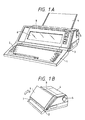
- Figs. 1A and 1B show a perspective view of an electronic typewriter with a device to which this invention is applicable.
- 1 is a keyboard, in which is arranged a group of keys 2, such as keys for entering characters, e.g. letters and numerals, a key for switching between a typewriter mode and a word processor mode, and control keys. When it is not used, it can be folded by turning it around a hinge 3, as shown in Fig. 1B.
- 4 is a feed paper tray for feeding a sheet-like recording medium onto a printer section within the apparatus, and can be also stored by folding over the printer section, as shown Fig. 1B, when not used.
- 5 is a feeder knob for setting or exhausting the recording medium manually
- 6 is a display for displaying input sentences or other data
- 7 is a handle used to transport the apparatus in accordance with this invention.
- FIG. 8 is a window constituting a cover for the electronic typewriter in accordance with this invention, and provided on an upper portion of the typewriter adjacent to the display 6, which enables an visual inspection of an ink jet printer and a recording medium that are accommodated therein, as described later.
- Fig. 2 shows a construction of a printer section according to an embodiment of this invention.
- a head cartridge having an ink jet recording head as will be described in detail with reference to Figs. 3 and 4, and 11 is a carriage for scanning in the S direction in Fig. 2 with the head cartridge 9 attached thereto.
- 13 is a hook for attaching the head cartridge 9 onto the carriage 11
- 15 is a lever for operating the hook 13.
- a marker 17 for enabling a print or set position with the recording head of the head cartridge to be read with an indication of scale provided on a cover as described later.
- 19 is a support plate for supporting an electrical connection to the head cartridge 9.
- 21 is a flexible cable for connecting between its electrical connection and a control section of main body.
- a guide shaft for guiding the carriage 11 in the S direction, which is inserted through bearings 25 of the carriage 11.
- 27 is a timing belt for transmitting a power to move the carriage 11 fixed thereto in the S direction, passing under tension about pulleys 29A, 29B arranged on both sides of the apparatus.
- a driving force is transmitted to one pulley 29B via a transmission, e.g. a gear, by a carriage motor 31.
- a conveying roller for conveying a recording medium, e.g. a paper (thereafter referred to as a recording paper) on recording, as well as regulating its recorded plane of the recording medium, and it is driven by a conveying motor 35.
- 37 is a paper pan for conducting a recording medium from the feed paper tray 4 to a recording position, and 39 is a feed roller, disposed on a way of feed path for the recording medium, for biasing the recording medium against the conveying roller 33 to convey it.
- 34 is a platen for regulating a recording face of the recording medium, opposed to a discharge port of the head cartridge 9.
- 41 is a paper exhausting roller for exhausing the recording medium to a paper exhausting port, not shown, which is disposed downstream from the recording position in the direction of conveying the recording medium.
- 42 is a spur provided correspondingly to the paper exhausting roller 41, for pressing the roller 41 via the recording medium, and developing a force for conveying the recording medium with the paper exhausting roller 41.
- 43 is a release lever for releasing the energized state for a feed roller 39, a presser bar 45, and a spur 42, when setting a recording medium.
- the presser bar 45 is a presser bar for suppressing the floating of a recording medium in a neighborhood of a recording position to secure a tight contact condition against the conveying roller 33.
- an ink jet recording head to record with the discharge of ink is used. Accordingly, as a distance between an ink discharge port formation face of the recording head and a recorded surface of the recording medium is relatively slight, and must be strictly controlled to avoid a contact between them, the presser bar 45 is effectively disposed.
- 47 is a scale provided on the presser bar 45, and 49 is a marked provided on the carriage 11 correspondingly to this scale, both enabling a print or set position for the recording head to be read.
- the cap 51 is a cap made of an elastic material, e.g. rubber, which is placed opposite to an ink discharge port formation face of the recording head in a home position, and supported so as to easily attach to/detach from the recording head.
- the cap 51 is used for protecting the recording head when it is not used, or in a suction recovery processing for the recording head.
- the suction recovery process is such a processing that the cap 51 is opposed to the discharge port formation face, and the ink is discharged from the whole discharge port, by driving energy generation elements provided inwardly of the ink discharge port and used for the ink discharge, thereby discharge faulty factors, such as bubbles, dusts, or thickened ink not suitable for recording are removed (predischarge), or otherwise, discharge faulty factors are removed by forcedly discharging the ink from the discharge port, while the discharge port formation face is covered with the cap 51.
- 53 is a pump used to suck the ink received within the cap 51 in the suction recovery process with the forced discharge or predischarge, as well as to exert a suction force for the forced discharge of ink.
- 55 is a waste ink tank for reserving waste ink sucked by the pump 53, and 57 is a tube communicating between the pump 53 and the waste ink tank 55.
- 59 is a blade for wiping the discharge port formation face of the recording head, which is movably held between a position for wiping during the movement of head and projecting onto the recording head, and a retracted position not engaging the discharge port formation face.
- 61 is a motor
- 63 is a cam mechanism for driving the pump 53 and moving the cap 51 and the blade 59, with the power transmitted from the motor 61.
- FIG. 3 is a perspective view showing the head cartridge 9 integral with a discharge unit 9a that is an ink jet recording head body and an ink tank 9b, where 906e is a click engaged by a hook 13 on the carriage 11 in attaching the head cartridge 9. As clearly shown, the click 906e is disposed within a whole extension of the recording head. Near the discharge unit 9a in front of the head cartridge 9 is provided an abutting portion for positioning, not shown. 906f is a head opening section provided in a standing orientation on the carriage 11, to which a support plate for supporting a flexible substrate (electrical connection portion) and a rubber pad is inserted.
- Figs. 4A and 4B are exploded perspective views showing the head cartridge as shown in Fig. 3, which is of a disposable type integrated with an ink reservoir section which is a supply source of ink, as described above.
- 911 is a heater board comprising an electricity heat conversion element (discharge heater) and a wiring made of Al for supplying the electric power, which are formed on a Si substrate with a film technique.
- 921 is a wiring substrate for the heater board, the corresponding wirings being connected with, for example, a wire bonding method.
- a roof plate provided with a diaphragm for restricting an ink flow path and a common liquid chamber, consisting of a resin material integrated with an orifice plate section in this embodiment.
- the carrier 930 is a carrier made of, for example, metal, and 950 is a presser spring, between which are engagingly carried the heater board 911 and the roof plate 940, which are thereby tightly fixed with the application force of the presser spring 950. It should be noted that the carrier 930 is pasted with the wiring substrate 921, and has a positioning reference to the carriage 11 for scanning with the head. The carrier 930 also functions as a cooling member for radiating the heat on the heater board 911 generated by driving.
- 960 is a supply tank, which functions as a subtank for receiving ink from an ink reservoir 9b which is an ink supply source and for conducting ink into the common liquid chamber formed by the joint of the heater board 911 and the roof plate 940.
- 970 is a filter disposed in a position within the supply tank 960 near an ink supply port into the common liquid chamber, and 980 is a lid member for the supply tank 960.
- 900 is an absorbing member for impregnating the ink, disposed within the ink tank body 9b.
- 1200 is a supply port for supplying the ink to a recording element 9a comprising each of portions 911 ⁇ 980 as above indicated, for allowing the impregnation of ink into the absorbing member 900 by injecting the ink through the supply port 1200, in a process before this unit is placed on a portion 1010 of the ink tank body 9b.
- 1100 is a lid member for the cartridge body
- 1300 is an atmosphere communicating port provided on the lid member for communicating the inside of the cartridge to the atmosphere.
- 1300A is a liquid repellent member disposed inwardly of the atmosphere communicating port 1300, whereby the leakage of ink through the atmosphere communicating port 1300 is prevented.
- the discharge unit 9a consisting of each of the portions 911 ⁇ 980 is positioned and disposed on the portion 1010.
- the positioning or fixing at this time can be performed, for example, by fitting a projection 1012 on the ink tank body 9b into a corresponding hole 931 on the carrier 930, thereby resulting in the head cartridge 9 as shown in Fig. 4B.
- the ink is supplied from the inside of the cartridge through a supply port 1200, a hole 932 on the carrier 930 and an inlet port of the supply tank 960 as shown on a back side in Fig. 4A into the supply tank 960, and after passing through the inside of the supply tank 960, flows out of an outlet port through an appropriate supply tube and an inlet port 942 on the roof plate 940 into the inside of the common liquid chamber.
- packings such as silicon rubber or butyl rubber are disposed, thereby sealing those connections to define an ink supply path.
- Fig. 5A and 5B are upper and side views showing a carriage 11 in detail, respectively.
- 606 is a support plate stood on a bottom portion of the carriage 11, for supporting a flexible substrate 604 and a rubber pad 605 having projection portions 605A corresponding to terminal pads formed in the substrate 604.
- the 607 is an abutting member which is also stood on the bottom portion in front of the carriage 11.
- the abutting member 607 is formed so that its wall thickness is thin, in order to preserve a largest space of ink tank within a limited range of space for disposing both the head cartridge 9 and the carriage 11.
- the extending direction of the ribs 608 is the movement direction of the carriage 11 so as to have a sufficient strength in withstand the movement of the head cartridge in the swivel direction when it is detached.
- the ribs 608 are formed to be about 0.1 mm forwardly of the discharge face when the head cartridge 9 is attached. Thereby, even when a recording paper protrudes toward the travel path of the recording head with any action, the recording paper is prevented from rubbing the discharge face, causing a damage.
- An operation lever 15 for attaching or detaching the head cartridge freely rotatably bears on a shaft 601d on the carriage body 11.
- a hook 13 is used to attach or detach the head cartridge 9, a portion of which is in engagement with a portion of the operation lever 15.
- the hook 13 can perform the above mentioned attaching or detaching operation by guiding a long hole 603c formed therein into a guide shaft 601c on the carriage body 11.
- the attaching or detaching mechansim consisting of the operation lever 15 and the hook 13 is provided laterally of the carriage 11, or in the side toward which the carriage 11 moves, the attaching or detaching mechanism does not create any large dead space due to the movement of the carriage.
- 601a is abutting portions for positioning the head cartridge in the left and right directions, provided at two locations on the both sides of an abutting member 607. It should be noted that for positioning the head cartridge in the left and right directions, an abutting portion 601f on the support plate 606 may be also used, in addition to the abutting portions 601a.
- 601b is an abutting portion to position it in the forward and backward directions, formed in a laterally underside portion of the abutting member 607.
- 601c is abutting portions to position it in the upper and lower directions, formed at two locations, i.e., in a laterally underside portion of the abutting member 607 and a laterally underside portion of the support plate.
- Figs. 6A and 6B are upper and left side views showing the state when the head cartridge 9 is attached onto the carriage 11, respectively.
- 906a is a direct contact portion provided on the head cartridge 9 so as to come into contact with an abutting portion of the carriage 11, when the recording head is attached, while 906b and 906c are also direct contact portions corresponding to the abutting portions 601b and 601c, respectively.
- the contact portion 906a of the head cartridge 9 is directly in contact with the abutting portion 601a of the carriage 6, while simultaneously the click 906 of the head cartridge 9 is forced to the left side in Fig. 6A, with the energized force of a coil spring 610 against the hook 13 engaged therein, whereby the head cartridge 9 is subject to the moment force around the above mentioned direct contact portion. Then a substrate 906d on the head is brought into direct contact with the abutting portion 601f, so that the head cartridge 9 can be positioned in both left and right directions, thereby holding that position.
- the projection portion 605A of the rubber pad 605 is compressed by coming into direct contact with the substrate 906d.
- This deformation causes a force pressing a terminal pad of the flexible substrate 604 into contact with a terminal of the substrate 906d, in which as the substrate 906d, is in direct contact with the abutting portion 601f, the amount of deformation for the projection portion 605A is kept constant, thereby causing a stable pressing force as indicated above.
- the forward or backward and upper or lower positioning for the head cartridge 9 can be performed in an attaching process.
- Fig. 7A is an exploded perspective view of the above mentioned carriage 11.
- 613 is a roller spring as described later
- 615 is a lever stop for mounting an operation lever 15 onto a mounting portion 617 on the carriage 11.
- 619 provided at one end portion of a flexible cable 21, is a mounting member for fixing upper edge portions of a flexible substrate 604 and a rubber pad 605 integrated therewith in this embodiment to the support plate 606, while 621 is also a mounting member for fixing lower edge portions thereof.
- a substrate cover 623 is provided for covering the flexible substrate 604 on the carriage side when the head cartridge 9 is not attached, and protecting the flexible substrate 604 and a circuit within the main body connected thereto, from a contact with hands of an operator and a breakage due to said contact or an action of an electrostatic force.
- This substrate cover 623 is rotatably secured into pins 621A on the lower edge portion mounting member 621 for the substrate.
- 625 is a spring for exerting a tendency to rotate the substrate cover 623 toward the direction of covering the flexible substrate 604, and 627 is a recess for housing the substrate cover 623 when the head cartridge 9 is attached.
- the substrate cover 623 When a head cartridge 9 is not attached, the substrate cover 623 covers a flexible substrate 604 with a biasing force of a spring 625, as shown in Fig. 7B. If the head cartridge 9 is attached from an upper side in the above state, the substrate cover 623 is rotated clockwise in Fig. 7B around pins 621A against the biasing force of the spring 625, with the engagement between the lower surface of the head cartridge and a cover operation portion 623A, or the engagement between an operator hand and the operation portion 623A.
- the cover 623 is housed in the recess 627 by being pressed against the lower surface of the head cartridge 9. It should be noted that if the head cartridge 9 is removed, the cover immediately returns to the state as shown in Fig. 7B, thereby protecting the substrate 604.
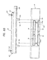
- Fig. 8A is a typical side view for mainly showing a recording medium conveying system of the apparatus as shown in Fig. 2.
- Fig. 8A shows an arrangement of each of elements in normally conveying a recording medium.
- the recording medium feeded from a feed paper tray not shown is introduced into a conveying path formed between a conveying roller 33 and a paper pan 37.
- the recording medium is conveyed with the friction force between the conveying roller 33 and the recording medium, based on the pressing force of the feed roller 39, by the conveying roller 33 rotating clockwise in Fig. 8A.
- the recording medium is introduced between the conveying roller 33 and a paper presser bar 45, and then also conveyed with the friction force between the conveying roller 33 and the recording medium, based on the pressing force of the paper presser bar 45.
- the recording medium is regulated in the direction by the paper presser bar 45, and conveyed along a platen 34 between a paper exhausting roller 41 and a spur 42, while the recording medium is recorded with the discharge of ink droplet from a recording head cartridge 9.
- Fig. 8B is a top view showing a paper pan 37, and a release plate for forcing it in the direction toward the conveying roller 33, which are separated for clarity of explanation.
- 40 is a release plate which is a member for pressing a feed roller 39 to a conveying roller 33 via a paper pan 37, and releasing that pressing force.
- the release plate 40 rotatably bears on an axis such that axis portions 40C provided on the ends thereof are in engagement with axis holes 101A on an axis member 101 on which the release plate 40 rotatably bears stood on a bottom plate 100 of the mechanism, so that this portion is forced obliquely in the right lower direction by a spring 401 engaging at two positions in one end portion of the release plate 40, the release plate 40 bears on the axis portion 40C to be rotatable clockwise, as shown in Fig. 8A.
- 371 is ribs provided at two locations underneath the paper pan 37. The ribs 371 is brought into contact with the pressing portion 40A during the above rotation of the release plate 40, and pressed upwardly in Fig. 8A. Thereby the feeder roller 39 which bears on the ribs 371 presses the conveying roller 33.
- the release of pressing force with the release plate 40 is performed in such a way that a shoulder 40B extending at one end of the release plate 40 is pressed downwardly in Fig. 8A against the rotation force owing to a spring 401. If this pressing force is released, the paper pan 37 and the feed roller 39 move downwardly by their weights, thereby providing a predefined amount of space between the feed roller 39 and the conveying roller 33.
- 372 is a rectangular projection portion formed when a portion of the paper pan 37 extends downwardly.
- a rectangular hole 372A which engages a projection 102 upstanding on the bottom plate 100 with a predetermined amount of space. With this engagement, the positioning of the paper pan 37, and hence the feed roller 39 with respect to the conveying roller 33 can be performed.
- the conveying roller 33 is rotated to convey it in a longer distance than a predetermined amount because of forcing it out. Consequently, such a problem occurred that a recording position on the recording medium is deviated.
- 451 is a spring for forcing the paper presser bar 45 in the direction toward the platen 33.
- the spring 451 has one end thereof extending from the coil-shaped portion engaged with a portion of the paper presser bar 45, and the other end engaged with a portion of the bottom plate 100 of the mechanism.
- the coil-shaped portion bears on a portion of the bottom plate 100.
- the paper presser bar 45 is pressed via a roller 91 on a leading portion of the carriage 11 against the carriage 11, as described later. The distance between a discharge port of the head cartridge 9 and a recording surface of the recording medium can be properly maintained by the pressing force via the roller 91 by the spring 45.
- the paper presser bar 45 also exerts the pressing force on the conveying roller 33 via the recording medium due to the pressing force as above described, thereby conveying the recording medium with a friction force between the recording medium and the conveying roller 33 based on that pressing force.
- the material of the paper presser bar 45 is POM (polyacetal), and that of the conveying roller 33 is CR (chloroprene rubber, hardness 60 degrees / A scale) mixed with 5 ⁇ 10% (weight ratio) of monofilament of nylon resin). Fluororesin can be also used for the paper presser bar 45.
- chloroprene rubber was 60 degrees, but if it is within a range of 50 and 70 degrees, it does not have an adverse effect on the conveyance of the recording paper. It is not necessary that the conveying roller 33 and the paper presser bar 45 are entirely made of above materials, only direct contact portions may be constructed of above materials, or further the paper presser bar and the conveying roller can be formed by pasting a sheet member of above material onto the body portion.
- the friction coefficient between the paper presser bar 45 and the recording medium can be reduced by constructing the paper presser bar and the conveying roller with above materials, such an arrangement as above described that the paper presser bar 45 presses against the conveying roller 33 can be embodied as described above. Consequently, a distance between the recording medium and the head cartridge can be controlled more easily than a previous arrangement which did not allow various paper thicknesses for the recording medium. As the friction coefficient between the recording medium and the conveying roller is larger, a slide does not occur during the conveyance, whereby the successful conveyance of the recording medium can be accomplished.
- Fig. 8A 46 is a shaft member which extends parallel to the paper presser bar 45, and on both ends of which bears a frame of device, with its cross-section being a D character shaped.
- the rotation position is determined so that a straight portion of D character is placed in a longitudinal direction (from the upper to the lower portion in Fig. 8A).
- the pressing force of the paper presser bar 45 against the conveying roller 33 is released, as shown in Figs. 10 and 11, the straight portion of the paper presser bar is directed transversely (from the left to the right direction in Fig.
- the head cartridge and the carriage does not interfere with the paper presser bar to thereby damage the head cartridge and the carriage.
- the pressing force against the paper presser bar 45 via the roller 91 is not released in this case, but this pressing force is directed to one point of a portion where the paper presser bar 45 is opposed to the carriage 11, and so it does not have any problem for inserting the recording medium.
- Fig. 8A 41 is a paper exhausting roller, with which a spur 42 engages.
- the spur 42 is energized against the paper exhausting roller 41 by the energizing means as shown in Figs. 10 and 11, in which the recording medium can be also conveyed with the friction force between the recording medium and the paper exhausting roller 41, based on that pressing force, as previously.
- the spur 42 is energized via a holding member 42A against the paper exhausting roller 41 as above described, and released from the engagement with the paper exhausting roller 41, by detaching it from the paper exhausting roller 41 via the holding member 42A.
- the paper pan 37 (feed roller 39), the paper presser bar 45 and the spur 42 as shown in Figs. 8A and 8B can release their energizing force in the respective forms. Those releases can be performed simultaneously by the operation of a release lever 43 as shown in Fig. 2, so that the state as shown in Fig. 8C occurs.
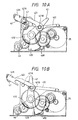
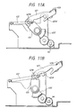
- Figs. 10A and 10B, and Figs. 11A and 11B are views showing the mechanism for releasing the above mentioned energizing force as indicated above, in which Figs. 10A and 10B show that mechanism on a recording apparatus viewed from the right side, while Figs. 11A and 11B show the same viewed from the left.
- Fig. 10A and Fig. 11A show a normal state where the energizing force in conveying a recording medium is not released. Then the release lever 43 which rotatably bears on a shaft of the conveying roller 33 is placed in a laid position due to the energizing force of a spring as described later, so that a cam member 431 fixed to the lever 43, a gear 432, and a gear 432′ disposed on the other end portion opposite to the end portion at which the lever 43 is disposed, and fixed to the shaft coaxial with that of the conveying roller 33 are in engagement with a shoulder portion 40B of the release plate 40 and a train of gears for rotating a shaft member 46, in the predetermined positional relations.
- Spur arms 421 and 421′ extending from the spur holding member 42 and disposed on both end portions thereof are forced backwardly of the device via the respective engagement portions 421B and 421B′ in engagement with the lever 43 and the connection member 433, by the tensile forces of the springs 422 and 422′.
- the engagement portions 421A and 421A′ on the respective spur arms can engage with the shaft of the paper exhausting roller 41, so that the appropriate engagement between the spur 42 and the paper exhausting roller 41 having the proper position and pressing force can be accomplished.
- the appropriate engagement of the spur 42 with the paper exhausting roller 41 can be performed without great precision of the shape for the spur arms 421.
- the rotation of the release lever 43 is transmitted via a gear 432 and a train of intermediate gears to the shaft member 46, and therefrom to a train of intermediate gears and a gear 432′ on the opposite side, and the connection member 433, finally moving the spur arm 421′.
- the looseness due to the backlash between gears interposed therein can be absorbed by the engagement with a looseness between the release lever 43 and the spur arm 421 as shown above.
- a member that can be released from the energized condition with the above construction is not limited to the spur, but may be any type of roller for conveying a recording medium.
- Figs. 10B and 11B show the state where the spur 42, the paper presser bar 45 and the paper pan 37 are released from the respective energizing conditions. These releases can be accomplished by rotating the release lever 43 forwardly of the device against the tensile force of the spring 422. In other words, if the release lever 43 is rotated, the gear 432 is rotated accordingly. Then, as described above, the shaft member 46 is rotated via the train of intermediate gears in engagement with the gear 432, thereby making the D character shaped straight line portion cross-wise, so that the shaft member 46 forces the spring 451 in the direction for narrowing the spring 451, as described above in Fig. 8A, thus releasing the engagement between the spring 451 and the paper presser bar 45 so as to eliminate the energizing force for the paper presser bar 45.
- a cam 431 can be rotated. With a cam portion of the cam member 431 is engaged the shoulder portion 40B of the release plate 40, as described above in Fig. 8, which lowers its position along with the rotations of the cam member 431, releasing the engagement with the ribs 371 of the paper pan 37, and hence the pressing against the ribs 371. Consequently, the force for energizing the paper pan 37 (feed roller 39) to the conveying roller 33 is released, and the paper pan 37 is lowered downwardly by its weight. With the rotation of the release lever 43, the shoulder portion 40B and the step-like cam portion of the cam member 431 are finally engaged, so that the engagement position thereof is fixed, and thereby the rotational position of the release lever 43 is fixed.
- the spur arm 421 moves forwardly of the device, and with the transmission of the rotation via the shaft member 46, as described above, the spur arm 421′ on the opposite end portion moves forwardly of the device, whereby the spur 42 connecting to the spur arms 421, 421′ is released from the engagement with the paper exhausting roller 41.
- Fig. 12 is a typical front view showing a knob fixed to the shaft of the conveying roller 33 and an assembled state of the release lever as above mentioned
- Fig. 13 is a typical exploded view.
- a driven gear 321 for rotating a conveying roller 33 is fixed to a shaft 333 of the conveying roller 33
- a knob 5 is fixed to the shaft 333 by a spring pin 332 drifted into the shaft 333.
- the release lever 43 freely rotatably bears on the shaft between them, but has a restricted range of rotation with a spring, as above described.
- Fig. 13 is a view for explaining a sequence of assembling the above construction.
- the spring pin 332 has been drifted into the shaft 333 beforehand, to which a gear is fixed.
- the release lever 43 is inserted into the shaft 333 in this state via an open section 43A.
- the open section 43A has a shape through which the shaft 333 and the spring pin 332 can be passed, as shown in Fig. 13, whereby the release lever 43 can move beyond a position where the spring pin 332 was drifted, to the side of gear 331.
- a knob 44 is fixed by fitting the spring pin 332 into a slit 5A while inserting the knob 5 into the shaft 333.
- the axial movement of the release lever 43 can be restricted by means of the gear 331 and the knob 5, and the knob 44 can be fixed by means of the spring pin 332.
- the spring pin 332 is drifted beforehand into the shaft 333, the assembling is simpler than a case where the spring pin is drifted after inserting the lever.
- Figs. 14 and 15 are side and upper views showing the mechanism around a head cartridge as shown in Fig. 2.
- 91 is a roller which freely rotatably bears on a shaft on a front end portion of the carriage 11, as previously described.
- the roller 91 is provided such that a portion thereof may project forwardly of a discharge port face of the head cartridge, rotating in direct contact with a paper presser bar 45.
- 613 is a roller spring provided on a trailing portion of the carriage 11.
- the roller spring 613 is comprised of a roller 613A, a connection member 613B which bears on the roller 613A, and a spring 613C for energizing the connection member 613B in a predetermined rotational direction.
- the roller 613A is brought into direct contact with a front end plate 105 stood extending parallel to a guide shaft as previously described at the front end portion of a bottom plate 100 in the device, on which it rolls.
- the connection member 613B freely rotatably bears on a predetermined shaft 113 of the carriage 11, while the spring 613C is carried on a predetermined axis to force the connection member 613B to rotate counterclockwise around the shaft 113.
- the bearing 25 is bearings for engaging with a guide shaft 23, mounted on both side end portions of the carriage 11.
- the bearings 25 has the bearing portion eccentric to a case to be mounted, in which two bearings 25 are mounted with the eccentric direction being opposite to each other.
- the bearing 25 on the side as shown in Fig. 14 is provided to swing around a boss 112 on the carriage 11. That is, portions in the carriage 11 to which the bearings 25 are mounted are formed with long holes, and two projections 25A of the bearings 25 are regulated in a forward or backward direction (the left or right direction in Fig. 14) movement by the boss 112. Consequently, the bearings 25 swing relative to the carriage 11, in correspondence with the movement of the carriage 11, as described later.
- the movement of the bearings 25 in the direction of the guide shaft 23 is regulated to a part of the carriage 11 (refer to Fig. 7A) by a projection 25B on the bearings 25.
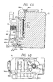
- a gap an interval between a recording medium and a discharge port face of the head cartridge, based on the construction of a roller 91, a roller spring 613 and bearings 25 will be described in the following.
- the automatic adjustment of the gap can be performed depending on the thickness of a recording medium inserted between a paper presser bar 45 and a platen roller 33.
- a left bearing 25 in Fig. 16 is located almost centrally in a long hole.
- a carriage 11 is forced toward the paper presser bar 45 by a reaction force from a front end plate 105 biased by a roll spring 613, whereby a roller 91 presses the paper presser bar 45.
- the respective reaction forces against the force with which the roller 91 presses the paper presser bar 45, and the force with which the above mentioned roller spring 613 biases the front end plate may cause the moments around the right bearing in Fig.
- the position of the bearing 25 in the long hole as indicated above can be determined when two moments are in equilibrium.
- a guide shaft 23 fixed to the body of device, and hence the position of the carriage 11 relative to the bearings 25 are determined, so that a gap d between a discharge port of the head cartridge 9 attached thereon and a recording medium can be determined.
- Fig. 16B shows a position of a carriage 11 when recording onto a relatively thick recording medium 93, e.g. an envelope.
- a roll 91, and hence the carriage 11 retract downwardly in Fig. 16B, due to the thickness of the recording medium, as compared with those in Fig. 16A.
- a reaction force from the front end plate 105 caused by the roll spring 613 changes, so that an equilibrium position of the above moments correspondingly changes. Consequently, a relative position between the bearing 25 on the left side in Fig. 16B and the carriage 11 changes, whereby the carriage 11 has its front end portion open to the left side in Fig. 16, and the gap between the discharge port and the recording medium is almost equal to a gap d in Fig. 16A.
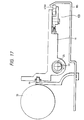
- the bearing 25 on the left side changes the position in the long hole by swinging relatively as indicated by arrow in Fig. 17.
- a recording medium thicker than an ordinary cardboard can be used with the positional change of the roller 91, or the paper presser plate 45 can be left away by a great amount corresponding to such a cardboard and keep the gap fixed, with the position of the roller 91.
- a roller spring 613 has a roller 613A pressed downwardly in Fig. 17, as the roller 613A is in direct contact with a bowed oblique portion of a front end plate 105, thereby pressing all the carriage 11 downwardly. Consequently, the carriage 11 is prevented from lifting up, to make stable the ink discharge direction from the head cartridge 9 attached thereon.
- 111 is a cut away portion on the left side lower portion of the carriage 11, to be engaged with a pulley axis 290A near a home position.
- This engagement is accomplished when the carriage 11 moves to a cap position on the discharge port face, and in this engaged position, the discharge port face is covered with a cap 51 (Fig. 2).
- the cap 51 is not detached from the discharge port face of the head cartridge 9 as the carriage 11 can not move in the forward or backward direction, thereby ensuring the capping.
- the pulley axis 290A is also used to engage with the cut away portion 111 of the carriage 11, no particular member is necessary for this engagement, resulting in a simple and cheap construction.
- the cut away portion 111 is formed with a beveled inlet portion so as to facilitate the engagement with the pulley axis 290. Thereby the engagement can be easily performed, even when the carriage 11 is displaced depending on the thickness of paper.
- Fig. 18 is a typical elevation view of the head cartridge 9 and the carriage 11 looked from a recording medium side. As clearly shown, the carriage 11 and the head cartridge 9 attached thereon are inclined to the guide shaft 23, and hence to the movement direction of the carriage 11, whereby the direction of the discharge port arrangement is also inclined.
- This inclination is made by using two bearings 25 whose bearing portions are eccentric as above described.
- the left bearing 25 (right in Fig. 18) is mounted with its eccentric position located downwardly, as seen in Fig. 14 and Fig. 17, while the right bearing 25 (left in Fig. 18) is mounted with its eccentric position located upwardly.
- the construction in which the discharge port arrangement is inclined as above shown is used when a plurality of discharge ports are driven with the time division.
- An ink jet recording head is generally driven with the time division on such a viewpoint that the recording speed and the drive power can not be increased.
- the recordings 95 are performed on a recording paper 94 as shown in Fig. 19A, including the carriage movement, when the discharge port arrangement is not inclined, and represent slanting lines as macroscopically seen.
- the discharge port arrangement is inclined as in this embodiment, the recordings 97 are performed on a recording paper 95 as shown in Fig. 19B, and represent vertical lines as macroscopically seen. It should be noted that this inclination is not only effective to the time division drive in each block, but also for the time division drive in each discharge port.
- the inclination according to this embodiment is performed by the bearings 25 mounted on both side end portions of the carriage 11, the precision of the inclination is easy to raise, because a distance between these bearings is relatively long. As it is only needed to mount one type of bearings in opposite vertical directions, the inclination is simply constructed. Further, when the timing for driving in the time division is different depending on the speed of the carriage, the inclination according to the above mentioned timing can be constructed by changing only the bearings without changes of the carriage and the recording head, whereby it is possible to make a common use of the carriage.
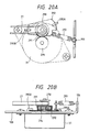
- Figs. 20A and 20B are upper and elevation views showing the detail near a pulley 29B disposed on the right end portion of the device, in which two pulleys are used to drive a timing bell for moving the carriage.
- a driven gear 291 On the pulley 29B is fixed coaxially a driven gear 291, which mates with a drive gear 294 fixed to the rotation axis of a carriage motor 31.
- a bracket 292 freely rotatably bears on a shaft to which the pulley 29B and the gear 291 are fixed.
- a spring 293 is connected to the bracket 292, while the other end thereof is connected to a projection 106 stood on a bottom plate 100.
- the bracket 292 is energized in the direction deviated by a predetermined angle from the direction along which the timing belt 27 extends.
- the bracket 292 (and the gear 291 and the pulley 29B which bear on a axis thereof) moves freely, except that it is restricted in the upper or lower direction and a predetermined direction along the bottom plate 100 by the L-shaped members 295A and 295B stood on the bottom plate 100. Accordingly, with the energizing force by the spring 293, the tension on the timing belt 27 and the mating force between the gear 291 and the gear 274 can be obtained according to the brach force.
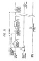
- Figs. 21 and 22 are a timing chart and a flow chart respectively, for showing the control procedure in the recording position instructed mode for an ink jet recording apparatus according to this embodiment.
- the recording position instructed mode in accordance with this embodiment is a control procedure that is activated when recording onto a formatted paper or a recording paper already once recorded, such as in an electronic typewriter in which a recording apparatus in accordance with this embodiment is used.
- the recording position and range are set and confirmed while moving the carriage (recording head), during which no ink droplet is discharged.
- a command for instructing recording position is a predetermined key input
- this control procedure is activated, a cap 51 is opened at step S201 (Fig. 21, only the timing is noted thereafter), and at step S202, the carriage 11 is moved toward an instructed position, for example, by the input of space key (timing 2).
- step S203 a determination is made whether the position is a predetermined key input for setting instructed position, as a result that the carriage 11 has reached to the instructed position, and if not, at S204, another determination is made whether a predetermined time T seconds have passed since the opening of the cap.
- a current position of the carriage 11 is stored at S205, and the carriage 11 is moved to a predischarge position at S206 (timing 3). Further, a predetermined amount of ink is predischarged (A times) at S207 (timing 4). Then at step S208, the carriage 11 is returned to the previously stored position, and at step S209, it is moved to the instructed position as above described. Meanwhile, at step S210, a determination is made whether the position is a predetermined key input for setting instructed position in the same way as above described, and if not, another determination is made whether a predetermined time ⁇ seconds have passed since the command for instructing position was issued, or this control procedure started, at step S211. This ⁇ seconds was set because the setting of the instructed position will be normally terminated during this time, and because if the recording head is kept open without the cap beyond that period, it will cause a significant damage to the discharge of ink droplet.
- step S211 If a negative determination is made at step S211, another determination is made at step S212 whether a predetermined time t seconds have passed since the previous predischarge, and if so, the processing proceeds to steps S213 and S214 which are the same as those above described, then predischarges B times at step S215, and returns to step S208.
- step S203 If the position is a predetermined key input for setting instructed position at step S203 or S210, the position is stored at step S216 or S217, and if a determination is made that ⁇ seconds have passed at step S211, the processing proceeds to step S218.
- step S218 the carriage 11 is moved to the capping position (timing 5), and is capped at step S219 (timing 6), the instruction mode is reset at step S220, and the processing terminates.
- the elapsed times T, t and ⁇ seconds as above indicated can be set depending on the temperature or humidity in the atmosphere, or may be automatically set based on the detection by a sensor, e.g., a thermal sensor.
- the movement to the instructed position with the control procedure as shown above can be performed while a user keeps the space key down, in which the position of the carriage 11 relative to a recording medium, or the position of the discharge port can be known, by using both a marker 49 on the carriage 11 and a scale 47 on the paper presser bar 45, as shown in Fig. 2 and Fig. 15. It should be noted that the position of the marker 49 is offset from that of the discharge port, this offset amount is prestored, and automatically corrected in the recording operations.
- the scale 47 is provided on a particular member of the ink jet recording apparatus, such as a paper presser bar 45, the adjustment of the recording medium can be performed in a significant proximity of the scale.
- the amount of movement of the carriage 11 can be known by using a marker on the lever as shown in Fig. 2 and Fig. 15, and a scale (not shown) indicated on a window on a cover of the device as shown in Fig. 1.
- the construction of using the markers 49, 17 and other scales is especially effective in returning the carriage to the interrupted position again, when the position confirming operation with the movement of carriage is interrupted due to the predischarge in an ink jet recording apparatus.
- Fig. 23 is a block diagram showing the control configuration for performing the controls as shown in Fig. 21 and Fig. 22.
- a capping position and a movement position of the carriage 11 can be known based on the detection with a recovery home sensor 65 and a carriage home sensor 67.
- the movement to the instructed position and the input for setting instructed position can be performed with a space key and other predefined keys on a keyboard 1.
- 1000 is a MPU for executing the control procedure as above indicated
- 1001 is a ROM for storing the control procedure as above indicated
- 1002 is a RAM for storing a current position of the carriage 11, or being used for a work area in the above mentioned control execution.
- An 1003 is a timer for measuring the time, such as T seconds, t seconds or ⁇ seconds.
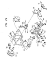
- Fig. 24 is an exploded perspective view showing a main portion of the recovery device comprising a cap 51, a pump 53, a blade 59, a motor 61 and a cam mechanism 63.
- 501 is an ink absorbing member disposed in the inside of the cap 51
- 503 is a holding member for holding the cap 51
- 505 is a cap lever rotatably attached around a pin 507, for bringing the cap 51 into direct contact with or separating it from a discharge port formation face of the discharge unit 9a by the force applied to the pin 507.
- 511 is a pin for regulating a range of rotation for the cap lever 505, engaged with an end portion 509 of the cap lever 505.
- 513 is a jig having a hole, into which the pin 507 of the cap lever 505 is fitted, which is used to attach the cap lever 505 onto a support 515 on the pump 53.
- 516 is a stop member for securing the attached state.
- 517 is a working section for exerting the force for bringing the cap 51 into direct contact with the discharge port formation face, which is engaged almost centrally in a back side portion of the cap 51.
- the working section is provided with an exhaust port 517A for sucked ink, and ink flow paths are formed inside the cap lever 505, the pin 507, the jig 513, and the support 515. If the pump 53 exerts the suction force, the ink is passed through these flow paths into the pump 53 as shown by arrow in Fig. 24.
- 519 is a shaft projecting from a center of end face of the pump 53 and internally formed with an ink flow path, and is rotatably attached on the side wall 520.
- the rotation force of the pump 53 is applied via the support 515 onto the cap lever 505, whereby the cap 51 moves outward or inward.
- 521 is a flow path formation member connected to the pump shaft 519
- 523 is an attachment member for a tube 57.
- the ink flow path is formed in the inside of the shaft 519, the flow path formation member 521 and the attachment member 523, in which the ink sucked by the pump 53 is introduced through those flow paths via the tube 57 into a waste ink tank 55, as indicated by arrow in Fig. 24.
- 525 is a piston for the pump 53
- 527 is a piston shaft
- 529 is a packing
- 532 is a cap of the pump 53.
- 533 is a pin attached to the piston shaft 527 and for receiving the transmitted force activating the piston 525.
- 535 is a blade lever to which a blade 59 is attached, rotatably supported around an axis projecting from the end face of the pump 53, and it projects or retracts the blade 59 toward or from the recording head side, along with the rotation.
- 537 is a spring for affording a rotational force to the blade lever 535 in the direction of projecting the blade 59.
- 539 is a spring for affording a tendency to rotate the pump 53 itself in the direction in which the cap 51 moves toward the recording head.
- a gear train for transmitting the rotation of the motor 61 to the cam mechanism 63 which comprises a cam 547 for engaging and rotating an engaging portion 545 on the pump 53, a cam 549 for engaging a pin 533 on the piston shaft 527 of the pump 53 and activating the pump, a cam 553 for engaging and rotating an engaging portion 551 on the blade lever 535, and a cam 557 for engaging a switch 555 detecting a home position of the cam mechanism 63.
- the operations of those cams will be described later.
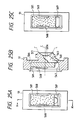
- a portion opposed to a recording head discharge port inside the cap is provided with an ink absorbing member 501 by two ribs 568, which is constructed not to entirely cover an ink suction port 561 provided in a vertically lower portion of the cap face, but to cover about more than half area of the ink inlet port 561.
- the ink absorbing member 501 has its upper end side contact with the upper end face 566 inside the cap 51, as well as with the cap face 565, the positioning of the ink absorbing member 501 is easy.
- a lower end face 567 inside the cap 51 is slightly upwardly inclined toward the ink suction port 561, facilitating the suction and removal of ink droplet.
- An ink flow path 563 communicates the ink suction port 561 with an ink exhaust port 517A, and is provided obliquely upwardly from the ink suction port 561 toward the ink exhaust port 517A.
- the ink flow path has a larger cross-section opening area of the ink suction port 561 than that of the ink exhaust port 517A.
- the ink absorbing member 501 was constructed to be contact with the lower end face 567 inside the cap 51, the ink impregnated in the ink absorbing member might often pass through the lower end face 567 to form droplets and stick to a discharge port face.
- the ink absorbing member 501 is constructed to uncover a lower portion of the ink suction port 561, the ink is impregnated and held in a vertical lower portion of the ink absorbing member 501.
- the ink is removed from inside the cap with the suction force of the ink suction means, through the ink suction port 561 which is open to the vertical lower portion inside the cap 51 and the vertical lower portion of the ink absorbing member 501.
- an ink jet recording apparatus is an electronic typewriter having a typewriter mode and a word processor mode
- the ink absorbing member 501 within the cap is exposed to the atmosphere.
- the ink absorbing member 501 may be dry and stiffened with the evaporation of water or alcohol content
- the lower portion of the ink suction port 561 is not covered with the ink absorbing member, but is placed in an open state, thereby maintaining the suction force of ink within the cap in the next predischarge operation.
- the ink absorbing member 501 is moistened with the ink predischarged at that time, so that the ink absorbing capability can be recovered again.
- the amount of ink exceeding an absorbing capacity of the ink absorbing member 501 may be occasionally discharged with the predischarge during that recording period.
- the ink absorbing member 501 is constructed to cover about more than half of an opening area of the ink suction port 561, the ink impregnated and held in the lower portion of the ink absorbing member 501 by the force of gravity is sucked by the ink suction means, and at the same time, the dropped ink is sucked through the ink suction port 561 open to the lower portion inside the cap, so that an effective suction and removal of ink can be accomplished.
- the ink suction port 561 has a shape of elongated oval having a longitudinal length of 2.25 mm and a transverse length of 1 mm.
- the ink absorbing member 561 covers the ink suction port 501 at the upper part of 1.25 mm.
- Fig. 25C shows another embodiment of a cap 51.
- an ink suction port 569 has an opening portion of at least almost the same width as that of a lower end face 567 (width of the ink absorbing member 501) inside the cap, a more effective suction and removal of ink within the cap can be accomplished.
- Fig. 25D is a cross-sectional side view of a cap 51 according to another embodiment of this invention. This embodiment is similar to that shown in Figs. 25B and 25C, except that an upper end portion of an ink absorbing member 501 is not contact with an upper end face 566 inside the cap 51.
- the ink absorbing member 501 is provided in a position opposed to an ink discharge port, the same effect as for previous embodiments was obtained.
- Fig. 25E is a typical cross-sectional side view of a cap 51 according to another embodiment of this invention.
- An ink absorbing member 501 is separated away from a face 568 opposed to an ink discharge port of the cap 51. Except for that portion, this embodiment is similar to those of Figs. 25B and 25C.
- the ink absorbing member 501 may be attached to an upper end face 566 on an interior side of the cap 51, or attached to a recess or through hole formed on the corresponding portion of the upper end face 566, so that the same effect as previous embodiments can be obtained.
- Figs. 25F to 25H are typical cross-section side views according to another embodiment of this invention.
- Fig. 25F, Fig. 25G and Fig. 25H was rotated clockwise by 90 degrees from Fig. 25B, Fig. 25D and Fig. 25H, respectively.
- the ink absorbed into an ink absorbing member 501 is sucked and exhausted from a portion of the ink suction port 561 covered with the ink absorbing member 501 through an ink flow path 563 out of an ink exhaust port 517A.
- the ink suction port 561 as shown in Figs. 25F to 25H can be replaced with an ink suction port 569 as shown in Fig. 25C, so that the ink within a cap 51 can be more effectively sucked and exhausted, and the suction force of the ink absorbing member 501 can be maintained.
- the flow path 563 within a cap 51 is constructed as shown in Fig. 25B, but if an ink suction path is provided on another portion, the ink flow path within the cap is not necessarily constructed as shown in Fig. 25B. In other words, if the ink suction port 561 is provided in a vertical lower portion of the cap 51, the ink flow path can be constructed as desired.
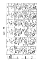
- Figs. 26 and 27 are views for explaining a profile curve of each cam in a cam mechanism 63, and an operation position of each portion corresponding to each cam position, respectively. Note that numerals shown in Fig. 26 are rotation angles of cam.
- FIGs. 26 and 27 show the cam position and the state of each portion at the recording operation, in which a cap 51 and a blade 59 are isolated from a discharge port formation face of the recording head, and a pump 53 is placed at an upper dead center.
- (B) is a position at which a home position switch 55 is turned off, which is defined to be a home position of the cam mechanism 63. This position is set, for example, while waiting for recording, where the cap 51 covers the discharge port formation face, the blade 59 is retracted, and the pump 53 is at an upper dead center.
- a piston 525 moves toward a lower dead center with the cap 51 joined to the discharge port formation face (cap on), thereby increasing a negative pressure of the suction system leading to the cap.
- the piston 525 arrives at an ink exhaust port of the pump, after a period of closing the pump (while a valve is closed), the valve begins to open (a point of 109.5 degrees), and completely opens (a point of 130.5 degrees), and the piston reaches to a point (C) near the lower dead center.
- the piston begins to move toward the upper dead center again.
- the valve begins to close (a point of 209.5 degrees), reaching to a point at which it is completely closed, while the cap 51 is completely isolated from the discharge port formation face at a position (E).
- the ink remaining in the ink suction system will be sucked into the pump side (idle suction).
- Left and right spaces of the piston 525 within the pump is communicated through a flow path not shown, which is closed when the piston moves from the upper dead center to the lower dead center, and opens when it moves from the lower dead center to the upper dead center.
- the space on the right hand of the piston communicates to a flow path on the pump axis 519. Accordingly, when the piston 525 moves from the lower dead center to the upper dead center in the idle suction, the ink introduced into the left space of the piston is transferred into the right space, and when it moves from the upper dead center to the lower dead center, the ink is introduced from the ink suction system into the left space, while it is exhausted from the right space to a waste ink tank.
- a blade 59 projects to be in a wiping state (position (F)). If the carriage 11 is moved to the recording area side in this state, the blade 11 engages with the discharge port formation of the head, wiping that surface to remove the ink deposited on the discharge port formation face. And the cam is further rotated to retract the blade 55, so that the cam is set at the position (A). In this state, the carriage 11 is moved to the cap side, so that the discharge port formation face of the head is opposed to the cap 51, and then the cam is moved to the position (B) to cap the head on, and is stopped.
- the cam When it is required to transfer to the recording, the cam is rotated in the positive or negative direction from the position (B), to project the blade 59, and then the recording can be performed after wiping with the blade 59.
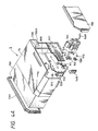
- Fig. 28 shows an example of a waste ink tank 55 according to this embodiment, in a state when a device is used.
- 181 is an ink absorbing member for holding waste ink
- 55A is used as a bottom portion when the device is used (the state in Fig. 1A)
- 55B is used as a bottom portion when the device is transported with a grip 6, housed as shown in Fig. 1B.
- 55C is an inclined surface which is never placed in the vertical downward direction, and in this embodiment, provided with a gas permeable cloth 183 thereon.
- This gas permeable cloth 183 passes the ink solvent vapor, but does not permeate the ink liquid, and more particularly, for example, a paper load (Teijin Limited) may be used.
- This invention has an excellent effect on a recording apparatus having a recording head with an ink jet recording method, especially a bubble jet recording method. With such a method, the higher density and definition of recording can be accomplished.
- the typical construction and principle is preferably based on a basic principle as disclosed in U.S. Patent No. 4,723,129 and No. 4,740,796 specifications.
- This method is applicable to both a so-called on-demand type and a continuance type, and particularly the on-demand type is more effective because the heat energy is developed on an electricity to heat conversion body by applying at least one drive signal causing a rapid rise of temperature exceeding that of the nucleus boiling corresponding to recording data, to a sheet in which the liquid (ink) is carried, and the electricity to heat conversion body disposed corresponding to a liquid path, causing the film boiling on the heat acting surface of the recording head, so that a bubble in the liquid (ink) can to formed corresponding one-to-one to that drive signal.
- the liquid (ink) With the growth and contraction of this bubble, the liquid (ink) is discharged via a discharge port to form at least one droplet.
- this drive signal is pulse-shaped, the growth or contraction of bubble is performed immediately and appropriately, and thus, the discharge of liquid (ink) is more preferably accomplished with the especially good response characteristic.
- the appropriate pulse-shaped drive signal was described in U.S. Patent No. 4,463,359 and No. 4,345,262 specifications. If the conditions as described in U.S. Patent No. 4,313,124 specification which is an invention concerning to the temperature-rise rate on the above mentioned heat acting surface are adopted, the more excellent recording can be performed.
- the construction of a recording head includes that as described in U.S. Patent No. 4,558,333 and No. 4,459,600 specifications which disclose a construction in which the heat acting portion is disposed in a bowed area, in addition to a combination of a discharge port, a liquid path and an electricity to heat conversion body (a straight liquid path or right angle liquid path).
- this invention is also effective with a construction based on Japanese Patent Laid-Open No. 59-123670 publication which discloses the use of a common slit as a discharge portion for a plurality of electricity to heat conversion bodies, and Japanese Patent Laid-open No. 59-138461 publication which discloses a construction in which an aperture absorbing the pressure wave of heat energy is corresponded to a discharge portion.
- the construction according to this invention enables the reliable and efficient recording in whatever form a recording head may be made.
- this invention is also effective for a full-line type recording head having the length that corresponds to that maximum recording length of a recording apparatus.
- a recording head is constructed in either a combination of a plurality of recording heads to fill that length, or one integrally formed recording head.
- this invention is also effective in using a replaceable chip type recording head which enables an electrical connection to an apparatus body and the supply of ink from the apparatus body, or a cartridge type recording head integrally formed on the recording head, because a serial type recording head as indicated in the above example can be also mounted onto the apparatus body.
- recovery means for a recording head or preliminary auxiliary means provided as a construction of a recording apparatus according to this invention, as it makes the effect of this invention more stable. More specifically, it includes capping means for a recording head, cleaning means, pressing or suction means, and preliminary heating means consisting of an electricity to heat conversion body or other heating elements or a combination of both, and a predischarge mode for discharging apart from recording is effective to make the stable recording.
- a recording head to be attached may be either of a single-head type corresponding to a mono color, or multiple-head type corresponding to a plurality of inks differing in recording color or density.
- an ink jet recording apparatus is used for an image output terminal in an information processing equipment such as a computer, a copying machine in combination with a reader, or a facsimile terminal equipment having the transmission and reception feature.
- an ink absorbing member when dry and stiffened with the evaporation of water or alchol content in a long time recording, as it is exposed to the atmosphere, the suction force of ink within a cap can be maintained.
- the ink can be sucked and removed effectively, owing to many times of predischarges.
Abstract
Description
- The present invention relates to a suction recovery device which is applicable to a printer, a copying machine, a facsimile terminal equipment, a typewriter, and a word processor that are generally used as a business machine, or an ink jet recording apparatus that is a complex equipment thereof. This invention is also effective especially for an electronic typewriter having a word processing feature.
- Conventionally, an arrangement that an absorbing member is disposed within a cap is typically disclosed in USP4,600,931. With this arrangement, a recording head is protected from being dry with a heat insulating effect of the cap, because the ink absorbing member impregnated with ink is disposed within the cap over which the recording head is capped. Another arrangement that an absorbing member is contained within a cap is known in USP4,543,589.
- Further, a capping device used in an ink jet recording apparatus is disclosed in British Laid-Open Patent Application No. 2,184,066, in which an ink suction port is provided on a lower portion within a cap, and an ink absorbing member is partially contained within said cap so as to entirely close said ink suction port therein.
- Recently, however, a recording time is increasingly longer, because ornamental characters or graphics are frequently used for recording, for example, in a word processor. During such a long recording time, the capping may be often omitted. The present inventor has found the following new problems from the investigation of those recent recording conditions.
- As an ink absorbing member disposed within a cap is subject to an atmosphere for a long time, there often occured a state in which the ink absorbed in the ink absorbing member becomes dry. This drying may cause a phenomenon where some amount of additive primarily contained therein such as color or pigment sticks to the absorbing member due to the evaporation of water or alcohol content in the ink. Thus a new problem occurs that the gas permeability of the ink absorbing member is deteriorated, thereby reducing the absorbing capability of the absorbing member.
- The present inventor also examined another main method with the predischarge (which is described in detail in GB2169855) to effect the recovery, wherein the use of an idle suction (which is described in detail in USP4,558,332) to suck and remove the ink makes the mechanism of device more complex, resulting in a problem that a more consumption power of device is needed, or that an increased volume of absorbing member requires a larger pumping power. Thus the present inventor has accomplished this invention as a result of carrying out various experiments to enhance the ink retention capability of an ink absorbing member as much as possible.
- It is an object of the present invention to provide a suction recovery device and an ink jet recording apparatus with said device having a new construction within a cap in which the above-referred-to problems are substantially reduced or overcome.
- It is another object of the invention to provide a suction recovery device and an ink jet recording apparatus provided with said device which enables an efficient recovery processing by reducing the number of idle suctions and maintaining the suction power capable of discharging a quantity of ink.
- It is another object of the invention to provide a suction recovery device comprising a cap for covering a face formed with a discharge port for discharging ink which is provided in a recording head for recording onto a recording medium with the discharge of said ink, said cap having an ink flow path containing an ink suction port on an interior side thereof, and an ink exhaust port communicating with said ink suction port and located on the other side opposite to said ink suction port, said ink flow path having an area of said ink exhaust port smaller than that of said ink suction port; an ink absorbing member disposed within said cap, said ink absorbing member covering a part of said ink suction port, and maintain the remaining part thereof open; and suction means for exerting a suction force into the inside of said cap, said suction means communicating with said ink exhaust port.
- It is another object of the invention to provide a suction recovery device comprising a cap for covering a face formed with a discharge port for discharging ink which is provided in a recording head for recording onto a recording medium with the discharge of said ink, said cap having an ink suction port on an interior side thereof, said ink suction port displaced downwardly from a centeral portion within said cap; and ink absorbing member disposed within said cap, said ink absorbing member covering an upper side of said ink suction port, and maintaining a lower side thereof open.
- Thus, in accordance with the invention, it is possible to achieve a significantly improved ink recovery ratio from a lower portion within a cap, with, at the same time, an enhanced ink retention capability of an ink absorbing member, thereby maintaining the condition within the cap excellent.
- It is another object of the invention to provide an ink jet recording apparatus comprising a recording head for recording onto a recording medium with the discharge of ink; a cap for covering a face formed with a discharge port for discharging ink in said recording head, said cap having an ink flow path with an ink suction port on an interior side thereof, and an ink exhaust port communicating with said ink suction port and located on the other side opposite to said ink suction port, said ink flow path having an area of said ink exhaust port smaller than that of said ink suction port; an ink absorbing member disposed within said cap, said ink absorbing member covering a part of said ink suction port, and maintains the remaining part thereof open; and suction means for exerting a suction force into the inside of said cap, said suction means communicating with said ink exhaust port.
- It is another object of the invention to provide an ink jet recording apparatus comprising a recording head for recording onto a recording medium with the discharge of ink; a cap for covering a face formed with a discharge port for discharging said ink in said recording head, said cap having an ink suction port on an interior side thereof, said ink suction port displaced downwardly from a centeral portion within said cap; and an ink absorbing member disposed within said cap, said ink absorbing member covering an upper side of said ink suction port, and maintaining a lower side thereof open.
- In accordance with the invention, it is possible to maintain a recording head excellent, and prevent the ink from sticking to a portion where the recording head is contact with a cap.
-
- Fig. 1A is a perspective view of an electronic typewriter with a device according to an embodiment of this invention, when it is used,
- Fig. 1B is a perspective view of an electronic typewriter with a device according to an embodiment of this invention, when it is stored,
- Fig. 2 is a perspective view showing a construction example of a printer applicable to an embodiment of this invention,
- Fig. 3 is a perspective view of a head cartridge as shown in Fig. 2,
- Fig. 4A is an exploded perspective view of a head cartridge as shown in Fig. 3,
- Fig. 4B is a perspective view of a head cartridge as shown in Fig. 3,
- Fig. 5A is an upper view of a carriage as shown in Fig. 2,
- Fig. 5B is a side view of a carriage as shown in Fig. 2,
- Fig. 6A is an upper view of the carriage with the head cartridge mounted thereon,
- Fig. 6B is a side view of the carriage with the head cartridge mounted thereon,
- Fig. 7A is an exploded perspective view of the carriage,
- Fig. 7B is a side view of the carriage,
- Fig. 7C is a side view of the carriage with the head cartridge mounted thereon,
- Fig. 8A is a cross-sectional side view of a recording medium conveying system on a printer as shown in Fig. 2,
- Fig. 8B is an exploded upper view of a recording medium conveying system on a printer as shown in Fig. 2,
- Fig. 8C is a cross-sectional side view of the conveying system with each energizing force released,
- Figs. 9A and 9B are typical side views showing the configuration for the run off of a feed roller in the conveying system,
- Fig. 10A is a side view of portions disposed on the right hand side of device in the mechanism for releasing the energized state of a feed roller, a paper presser bar and a spur on the conveying system, before releasing it,
- Fig. 10B is a side view of portions disposed on the right hand side of device in the mechanism for releasing the energized state of a feed roller, a paper presser bar and a spur on the conveying system, after releasing it,
- Fig. 11A is a side view of portions disposed on the left hand side of the same device, before releasing it,
- Fig. 11B is a side view of portions disposed on the left hand side of the same device, after releasing it,
- Fig. 12 is a typical front view showing the engagement between a lever and a knob which are used to release the energized state,
- Fig. 13 is an exploded perspective view of a mechanism as shown in Fig. 12,
- Fig. 14 is a side view showing the engagement relation of the carriage with other elements,
- Fig. 15 is an upper view showing the engagement relation of the carriage with other elements,
- Figs. 16A and 16B are typical upper views showing how the carriage changes its position depending on the thickness of a recording medium,
- Fig. 17 is a typical side view showing how a guide bearing changes along with changes as above indicated,
- Fig. 18 is a typical front view showing a mechanism for inclining an arrangement of discharge ports to the movement direction of the carriage,
- Fig. 19A is a typical plan view showing a recording example without the inclination mechanism,
- Fig. 19B is a typical plan view showing a recording example with the inclination mechanism,
- Fig. 20A is an upper view showing a tension mechanism of belt and its drive mechanism for driving a carriage as shown in Fig. 2,
- Fig. 20B is a front view showing a tension mechanism of belt and its drive mechanism for driving a carriage as shown in Fig. 2,
- Fig. 21 is a timing chart in a recording position instruction mode for a recording apparatus according to an embodiment of this invention,
- Fig. 22 is a flowchart in a recording position instruction mode for a recording apparatus according to an embodiment of this invention,
- Fig. 23 is a block diagram showing a control configuration of the above indicated mode,
- Fig. 24 is an exploded perspective view of a suction recovery mechanism as shown in Fig. 2,
- Fig. 25A is a front view of a cap portion on the suction recovery mechanism according to an embodiment of this invention,
- Fig. 25B is a cross-sectional side view taken along a line M-M of Gi. 25A,
- Fig. 25C is a front view of a cap portion on a suction recovery mechanism according to another embodiment of this invention,
- Fig. 25D is a front view of a cap portion on the suction recovery mechanism according to another embodiment of this invention,
- Fig. 25E is a typical cross-sectional side view of a cap portion on the suction recovery mechanism according to another embodiment of this invention,
- Fig. 25F is a typical cross-sectional side view of a cap portion on the suction recovery mechanism according to another embodiment of this invention,
- Fig. 25G is a typical cross-sectional side view of a cap portion on the suction recovery mechanism according to another embodiment of this invention,
- Fig. 25H is a typical cross-sectional side view of a cap portion on the suction recovery mechanism according to another embodiment of this invention,
- Fig. 26 is a timing chart showing a series of recovery operations on the suction recovery mechanism,
- Fig. 27 is a view showing, in time-series, the state of each section in the suction recovery operations on the suction recovery mechanism,
- Fig. 28 is a typical perspective view of a waste ink tank for reserving ink discharged by the recovery operation,
- Fig. 29A is a view showing an arrangement of the waste ink tank when a printer is used,
- Fig. 29B is a view showing an arrangement of the waste ink tank when a printer is stored.
- An embodiment of this invention will be described in detail with reference to the annexed drawings.
- Figs. 1A and 1B show a perspective view of an electronic typewriter with a device to which this invention is applicable. 1 is a keyboard, in which is arranged a group of
keys 2, such as keys for entering characters, e.g. letters and numerals, a key for switching between a typewriter mode and a word processor mode, and control keys. When it is not used, it can be folded by turning it around ahinge 3, as shown in Fig. 1B. 4 is a feed paper tray for feeding a sheet-like recording medium onto a printer section within the apparatus, and can be also stored by folding over the printer section, as shown Fig. 1B, when not used. 5 is a feeder knob for setting or exhausting the recording medium manually, 6 is a display for displaying input sentences or other data, and 7 is a handle used to transport the apparatus in accordance with this invention. - 8 is a window constituting a cover for the electronic typewriter in accordance with this invention, and provided on an upper portion of the typewriter adjacent to the
display 6, which enables an visual inspection of an ink jet printer and a recording medium that are accommodated therein, as described later. - Fig. 2 shows a construction of a printer section according to an embodiment of this invention.
- 9 is a head cartridge having an ink jet recording head, as will be described in detail with reference to Figs. 3 and 4, and 11 is a carriage for scanning in the S direction in Fig. 2 with the
head cartridge 9 attached thereto. 13 is a hook for attaching thehead cartridge 9 onto thecarriage hook 13. On thislever 15 is provided amarker 17 for enabling a print or set position with the recording head of the head cartridge to be read with an indication of scale provided on a cover as described later. 19 is a support plate for supporting an electrical connection to thehead cartridge 9. 21 is a flexible cable for connecting between its electrical connection and a control section of main body. - 23 is a guide shaft for guiding the
carriage 11 in the S direction, which is inserted throughbearings 25 of thecarriage 11. 27 is a timing belt for transmitting a power to move thecarriage 11 fixed thereto in the S direction, passing under tension aboutpulleys pulley 29B via a transmission, e.g. a gear, by acarriage motor 31. - 33 is a conveying roller for conveying a recording medium, e.g. a paper (thereafter referred to as a recording paper) on recording, as well as regulating its recorded plane of the recording medium, and it is driven by a conveying
motor 35. 37 is a paper pan for conducting a recording medium from thefeed paper tray 4 to a recording position, and 39 is a feed roller, disposed on a way of feed path for the recording medium, for biasing the recording medium against the conveyingroller 33 to convey it. 34 is a platen for regulating a recording face of the recording medium, opposed to a discharge port of thehead cartridge 9. 41 is a paper exhausting roller for exhausing the recording medium to a paper exhausting port, not shown, which is disposed downstream from the recording position in the direction of conveying the recording medium. 42 is a spur provided correspondingly to thepaper exhausting roller 41, for pressing theroller 41 via the recording medium, and developing a force for conveying the recording medium with thepaper exhausting roller 41. 43 is a release lever for releasing the energized state for afeed roller 39, apresser bar 45, and aspur 42, when setting a recording medium. - 45 is a presser bar for suppressing the floating of a recording medium in a neighborhood of a recording position to secure a tight contact condition against the conveying
roller 33. In this embodiment, an ink jet recording head to record with the discharge of ink is used. Accordingly, as a distance between an ink discharge port formation face of the recording head and a recorded surface of the recording medium is relatively slight, and must be strictly controlled to avoid a contact between them, thepresser bar 45 is effectively disposed. 47 is a scale provided on thepresser bar carriage 11 correspondingly to this scale, both enabling a print or set position for the recording head to be read. - 51 is a cap made of an elastic material, e.g. rubber, which is placed opposite to an ink discharge port formation face of the recording head in a home position, and supported so as to easily attach to/detach from the recording head. The
cap 51 is used for protecting the recording head when it is not used, or in a suction recovery processing for the recording head. The suction recovery process is such a processing that thecap 51 is opposed to the discharge port formation face, and the ink is discharged from the whole discharge port, by driving energy generation elements provided inwardly of the ink discharge port and used for the ink discharge, thereby discharge faulty factors, such as bubbles, dusts, or thickened ink not suitable for recording are removed (predischarge), or otherwise, discharge faulty factors are removed by forcedly discharging the ink from the discharge port, while the discharge port formation face is covered with thecap 51. - 53 is a pump used to suck the ink received within the
cap 51 in the suction recovery process with the forced discharge or predischarge, as well as to exert a suction force for the forced discharge of ink. 55 is a waste ink tank for reserving waste ink sucked by thepump pump 53 and thewaste ink tank 55. - 59 is a blade for wiping the discharge port formation face of the recording head, which is movably held between a position for wiping during the movement of head and projecting onto the recording head, and a retracted position not engaging the discharge port formation face. 61 is a motor, and 63 is a cam mechanism for driving the
pump 53 and moving thecap 51 and theblade 59, with the power transmitted from themotor 61. - Next, a
head cartridge 9 will be described in detail. Fig. 3 is a perspective view showing thehead cartridge 9 integral with adischarge unit 9a that is an ink jet recording head body and anink tank 9b, where 906e is a click engaged by ahook 13 on thecarriage 11 in attaching thehead cartridge 9. As clearly shown, theclick 906e is disposed within a whole extension of the recording head. Near thedischarge unit 9a in front of thehead cartridge 9 is provided an abutting portion for positioning, not shown. 906f is a head opening section provided in a standing orientation on thecarriage 11, to which a support plate for supporting a flexible substrate (electrical connection portion) and a rubber pad is inserted. - Figs. 4A and 4B are exploded perspective views showing the head cartridge as shown in Fig. 3, which is of a disposable type integrated with an ink reservoir section which is a supply source of ink, as described above. 911 is a heater board comprising an electricity heat conversion element (discharge heater) and a wiring made of Al for supplying the electric power, which are formed on a Si substrate with a film technique. 921 is a wiring substrate for the heater board, the corresponding wirings being connected with, for example, a wire bonding method.
- 940 is a roof plate provided with a diaphragm for restricting an ink flow path and a common liquid chamber, consisting of a resin material integrated with an orifice plate section in this embodiment.
- 930 is a carrier made of, for example, metal, and 950 is a presser spring, between which are engagingly carried the
heater board 911 and theroof plate 940, which are thereby tightly fixed with the application force of thepresser spring 950. It should be noted that thecarrier 930 is pasted with thewiring substrate 921, and has a positioning reference to thecarriage 11 for scanning with the head. Thecarrier 930 also functions as a cooling member for radiating the heat on theheater board 911 generated by driving. - 960 is a supply tank, which functions as a subtank for receiving ink from an
ink reservoir 9b which is an ink supply source and for conducting ink into the common liquid chamber formed by the joint of theheater board 911 and theroof plate 940. 970 is a filter disposed in a position within thesupply tank 960 near an ink supply port into the common liquid chamber, and 980 is a lid member for thesupply tank 960. - 900 is an absorbing member for impregnating the ink, disposed within the ink tank body 9b. 1200 is a supply port for supplying the ink to a
recording element 9a comprising each ofportions 911 ∼ 980 as above indicated, for allowing the impregnation of ink into the absorbingmember 900 by injecting the ink through thesupply port 1200, in a process before this unit is placed on aportion 1010 of theink tank body 9b. - 1100 is a lid member for the cartridge body, and 1300 is an atmosphere communicating port provided on the lid member for communicating the inside of the cartridge to the atmosphere. 1300A is a liquid repellent member disposed inwardly of the
atmosphere communicating port 1300, whereby the leakage of ink through theatmosphere communicating port 1300 is prevented. - After the ink is filled via the
supply port 1200 into theink tank 9b, thedischarge unit 9a consisting of each of theportions 911 ∼ 980 is positioned and disposed on theportion 1010. The positioning or fixing at this time can be performed, for example, by fitting aprojection 1012 on theink tank body 9b into acorresponding hole 931 on thecarrier 930, thereby resulting in thehead cartridge 9 as shown in Fig. 4B. - And the ink is supplied from the inside of the cartridge through a
supply port 1200, ahole 932 on thecarrier 930 and an inlet port of thesupply tank 960 as shown on a back side in Fig. 4A into thesupply tank 960, and after passing through the inside of thesupply tank 960, flows out of an outlet port through an appropriate supply tube and aninlet port 942 on theroof plate 940 into the inside of the common liquid chamber. At the connections for communicating the ink as indicated above, packings such as silicon rubber or butyl rubber are disposed, thereby sealing those connections to define an ink supply path. - Fig. 5A and 5B are upper and side views showing a
carriage 11 in detail, respectively. - 606 is a support plate stood on a bottom portion of the
carriage 11, for supporting aflexible substrate 604 and arubber pad 605 havingprojection portions 605A corresponding to terminal pads formed in thesubstrate 604. - 607 is an abutting member which is also stood on the bottom portion in front of the
carriage 11. The abuttingmember 607 is formed so that its wall thickness is thin, in order to preserve a largest space of ink tank within a limited range of space for disposing both thehead cartridge 9 and thecarriage 11. Hence, on themember 607 are formed threeribs 608 to secure the strength thereof. The extending direction of theribs 608 is the movement direction of thecarriage 11 so as to have a sufficient strength in withstand the movement of the head cartridge in the swivel direction when it is detached. Theribs 608 are formed to be about 0.1 mm forwardly of the discharge face when thehead cartridge 9 is attached. Thereby, even when a recording paper protrudes toward the travel path of the recording head with any action, the recording paper is prevented from rubbing the discharge face, causing a damage. - An
operation lever 15 for attaching or detaching the head cartridge freely rotatably bears on ashaft 601d on thecarriage body 11. Ahook 13 is used to attach or detach thehead cartridge 9, a portion of which is in engagement with a portion of theoperation lever 15. Thehook 13 can perform the above mentioned attaching or detaching operation by guiding a long hole 603c formed therein into aguide shaft 601c on thecarriage body 11. - As the attaching or detaching mechansim consisting of the
operation lever 15 and thehook 13 is provided laterally of thecarriage 11, or in the side toward which thecarriage 11 moves, the attaching or detaching mechanism does not create any large dead space due to the movement of the carriage. - Next, an abutting portion used to position the head cartridge when attaching thereto will be described.
- 601a is abutting portions for positioning the head cartridge in the left and right directions, provided at two locations on the both sides of an abutting
member 607. It should be noted that for positioning the head cartridge in the left and right directions, an abuttingportion 601f on thesupport plate 606 may be also used, in addition to the abuttingportions 601a. - 601b is an abutting portion to position it in the forward and backward directions, formed in a laterally underside portion of the abutting
member 607. - 601c is abutting portions to position it in the upper and lower directions, formed at two locations, i.e., in a laterally underside portion of the abutting
member 607 and a laterally underside portion of the support plate. - Figs. 6A and 6B are upper and left side views showing the state when the
head cartridge 9 is attached onto thecarriage 11, respectively. - In Figs. 6A and 6B, 906a is a direct contact portion provided on the
head cartridge 9 so as to come into contact with an abutting portion of thecarriage 11, when the recording head is attached, while 906b and 906c are also direct contact portions corresponding to the abuttingportions - Referring now to Fig. 6A, the engagement relations between various portions when the recording head is attached will be outlined.
- The
contact portion 906a of thehead cartridge 9 is directly in contact with the abuttingportion 601a of thecarriage 6, while simultaneously theclick 906 of thehead cartridge 9 is forced to the left side in Fig. 6A, with the energized force of acoil spring 610 against thehook 13 engaged therein, whereby thehead cartridge 9 is subject to the moment force around the above mentioned direct contact portion. Then a substrate 906d on the head is brought into direct contact with the abuttingportion 601f, so that thehead cartridge 9 can be positioned in both left and right directions, thereby holding that position. - At this time, the
projection portion 605A of therubber pad 605 is compressed by coming into direct contact with the substrate 906d. This deformation causes a force pressing a terminal pad of theflexible substrate 604 into contact with a terminal of the substrate 906d, in which as the substrate 906d, is in direct contact with the abuttingportion 601f, the amount of deformation for theprojection portion 605A is kept constant, thereby causing a stable pressing force as indicated above. - In the Fig. 6A, the compressed state of the
projection portion 605A is not shown. - The forward or backward and upper or lower positioning for the
head cartridge 9 can be performed in an attaching process. - Fig. 7A is an exploded perspective view of the above mentioned
carriage 11. - Here, 613 is a roller spring as described later, and 615 is a lever stop for mounting an
operation lever 15 onto a mountingportion 617 on thecarriage 11. 619, provided at one end portion of aflexible cable 21, is a mounting member for fixing upper edge portions of aflexible substrate 604 and arubber pad 605 integrated therewith in this embodiment to thesupport plate 606, while 621 is also a mounting member for fixing lower edge portions thereof. - In addition to the construction as above mentioned, a
substrate cover 623 is provided for covering theflexible substrate 604 on the carriage side when thehead cartridge 9 is not attached, and protecting theflexible substrate 604 and a circuit within the main body connected thereto, from a contact with hands of an operator and a breakage due to said contact or an action of an electrostatic force. Thissubstrate cover 623 is rotatably secured intopins 621A on the lower edgeportion mounting member 621 for the substrate. 625 is a spring for exerting a tendency to rotate thesubstrate cover 623 toward the direction of covering theflexible substrate substrate cover 623 when thehead cartridge 9 is attached. - Referring now to Figs. 7B and 7C, the operation of the
substrate cover 623 will be described. When ahead cartridge 9 is not attached, thesubstrate cover 623 covers aflexible substrate 604 with a biasing force of aspring 625, as shown in Fig. 7B. If thehead cartridge 9 is attached from an upper side in the above state, thesubstrate cover 623 is rotated clockwise in Fig. 7B around pins 621A against the biasing force of thespring 625, with the engagement between the lower surface of the head cartridge and acover operation portion 623A, or the engagement between an operator hand and theoperation portion 623A. And if thehead cartridge 9 is completely attached, and thesubstrate 604 is placed in direct contact with the substrate 906d on the head side, thecover 623 is housed in therecess 627 by being pressed against the lower surface of thehead cartridge 9. It should be noted that if thehead cartridge 9 is removed, the cover immediately returns to the state as shown in Fig. 7B, thereby protecting thesubstrate 604. - Fig. 8A is a typical side view for mainly showing a recording medium conveying system of the apparatus as shown in Fig. 2.
- Fig. 8A shows an arrangement of each of elements in normally conveying a recording medium. The recording medium feeded from a feed paper tray not shown is introduced into a conveying path formed between a conveying
roller 33 and apaper pan 37. In this conveying path, the recording medium is conveyed with the friction force between the conveyingroller 33 and the recording medium, based on the pressing force of thefeed roller 39, by the conveyingroller 33 rotating clockwise in Fig. 8A. Thereafter, the recording medium is introduced between the conveyingroller 33 and apaper presser bar 45, and then also conveyed with the friction force between the conveyingroller 33 and the recording medium, based on the pressing force of thepaper presser bar 45. Further, the recording medium is regulated in the direction by thepaper presser bar 45, and conveyed along aplaten 34 between apaper exhausting roller 41 and aspur 42, while the recording medium is recorded with the discharge of ink droplet from arecording head cartridge 9. - Fig. 8B is a top view showing a
paper pan 37, and a release plate for forcing it in the direction toward the conveyingroller 33, which are separated for clarity of explanation. - Referring now to Figs. 8A and 8B, the mechanism for conveying a recording medium will be described. 40 is a release plate which is a member for pressing a
feed roller 39 to a conveyingroller 33 via apaper pan 37, and releasing that pressing force. Therelease plate 40 rotatably bears on an axis such thataxis portions 40C provided on the ends thereof are in engagement withaxis holes 101A on anaxis member 101 on which therelease plate 40 rotatably bears stood on abottom plate 100 of the mechanism, so that this portion is forced obliquely in the right lower direction by aspring 401 engaging at two positions in one end portion of therelease plate 40, therelease plate 40 bears on theaxis portion 40C to be rotatable clockwise, as shown in Fig. 8A. 371 is ribs provided at two locations underneath thepaper pan 37. Theribs 371 is brought into contact with thepressing portion 40A during the above rotation of therelease plate 40, and pressed upwardly in Fig. 8A. Thereby thefeeder roller 39 which bears on theribs 371 presses the conveyingroller 33. - The release of pressing force with the
release plate 40 is performed in such a way that ashoulder 40B extending at one end of therelease plate 40 is pressed downwardly in Fig. 8A against the rotation force owing to aspring 401. If this pressing force is released, thepaper pan 37 and thefeed roller 39 move downwardly by their weights, thereby providing a predefined amount of space between thefeed roller 39 and the conveyingroller 33. - 372 is a rectangular projection portion formed when a portion of the
paper pan 37 extends downwardly. In theprojection portion 372 is provided arectangular hole 372A, which engages aprojection 102 upstanding on thebottom plate 100 with a predetermined amount of space. With this engagement, the positioning of thepaper pan 37, and hence thefeed roller 39 with respect to the conveyingroller 33 can be performed. - With the arrangement having a looseness in the above engagement, an adverse effect due to so called a kicking, which occurs when a trailing portion of a recording medium M to be conveyed passes through the
feed roller 39, can be eliminated. While the recording medium M is transferred from the state where a trailing portion of the recording medium is pressed against the conveyingroller 33 by thefeed roller 39 as shown in Fig. 9A, to the state where thefeed roller 39 and the conveyingroller 33 are in direct contact with each other as shown in Fig. 9B, it is forced out between thefeed roller 39 and the conveyingroller 33, in which even if the recording medium M is an envelope or a cardboard, such a kicking phenomenon is never caused by the force exerting on various portions in forcing the recording medium out. For example, in the arrangement where thefeed roller 39 can not escape in a reverse direction to the direction of forcing the recording medium out, the conveyingroller 33 is rotated to convey it in a longer distance than a predetermined amount because of forcing it out. Consequently, such a problem occurred that a recording position on the recording medium is deviated. - On the contrary, in the arrangement in accordance with this embodiment as shown in Fig. 8A, Figs. 9A and 9B, as the paper pan can escape by a distance d in the above engagement in the right direction in figures, when the trailing portion of the recording medium is forced out, the force due to the extrusion will not be exerted on the recording medium and the conveying
roller 33, so that such a problem as above mentioned does not occur. - Referring now to Fig. 8A again, 451 is a spring for forcing the
paper presser bar 45 in the direction toward theplaten 33. Thespring 451 has one end thereof extending from the coil-shaped portion engaged with a portion of thepaper presser bar 45, and the other end engaged with a portion of thebottom plate 100 of the mechanism. The coil-shaped portion bears on a portion of thebottom plate 100. Thepaper presser bar 45 is pressed via aroller 91 on a leading portion of thecarriage 11 against thecarriage 11, as described later. The distance between a discharge port of thehead cartridge 9 and a recording surface of the recording medium can be properly maintained by the pressing force via theroller 91 by thespring 45. - The
paper presser bar 45 also exerts the pressing force on the conveyingroller 33 via the recording medium due to the pressing force as above described, thereby conveying the recording medium with a friction force between the recording medium and the conveyingroller 33 based on that pressing force. - Here, to convey successfully various types of recording media, it is requisite to make appropriate the friction force betweeen the paper presser bar and the recording medium, and between the conveying roller and the recording medium. In other words, it is desirable that the friction force between the paper presser bar and the recording medium is as small as possible, while that between the conveying roller and the recording medium is as large as possible.
- Further, it is also desired to make the friction force between the paper presser bar and the conveying roller as small as possible. This is because if that friction force is large, the motor load becomes large at a so-called idle feeding. If a predetermined amount of gap is provided between the paper presser bar and the conveying roller to avoid it, the precision control becomes difficult with respect to the pressing force of the recording medium against the platen.
- Hence, in this embodiment, the material of the
paper presser bar 45 is POM (polyacetal), and that of the conveyingroller 33 is CR (chloroprene rubber, hardness 60 degrees / A scale) mixed with 5 ∼ 10% (weight ratio) of monofilament of nylon resin). Fluororesin can be also used for thepaper presser bar 45. - It should be noted that the hardness of above mentioned chloroprene rubber was 60 degrees, but if it is within a range of 50 and 70 degrees, it does not have an adverse effect on the conveyance of the recording paper. It is not necessary that the conveying
roller 33 and thepaper presser bar 45 are entirely made of above materials, only direct contact portions may be constructed of above materials, or further the paper presser bar and the conveying roller can be formed by pasting a sheet member of above material onto the body portion. - As the friction coefficient between the
paper presser bar 45 and the recording medium can be reduced by constructing the paper presser bar and the conveying roller with above materials, such an arrangement as above described that thepaper presser bar 45 presses against the conveyingroller 33 can be embodied as described above. Consequently, a distance between the recording medium and the head cartridge can be controlled more easily than a previous arrangement which did not allow various paper thicknesses for the recording medium. As the friction coefficient between the recording medium and the conveying roller is larger, a slide does not occur during the conveyance, whereby the successful conveyance of the recording medium can be accomplished. - In Fig. 8A, 46 is a shaft member which extends parallel to the
paper presser bar 45, and on both ends of which bears a frame of device, with its cross-section being a D character shaped. When a recording medium is conveyed, the rotation position is determined so that a straight portion of D character is placed in a longitudinal direction (from the upper to the lower portion in Fig. 8A). On the other hand, when the pressing force of thepaper presser bar 45 against the conveyingroller 33 is released, as shown in Figs. 10 and 11, the straight portion of the paper presser bar is directed transversely (from the left to the right direction in Fig. 8A) so as to come into direct contact with a portion of thespring 451, so that the spring is displaced, thereby releasing the engagement between thespring 451 and thepaper presser bar 45. Thus, the pressing force is only released without changing the position of thepaper presser bar 45. - Consequently, even if the carriage is operated with the pressing force being released due to the insertion of a recording medium, the head cartridge and the carriage does not interfere with the paper presser bar to thereby damage the head cartridge and the carriage. In other words, it is possible to perform various operations by moving the carriage, even while the pressing force of the paper presser bar is being released. The pressing force against the
paper presser bar 45 via theroller 91 is not released in this case, but this pressing force is directed to one point of a portion where thepaper presser bar 45 is opposed to thecarriage 11, and so it does not have any problem for inserting the recording medium. - In Fig. 8A, 41 is a paper exhausting roller, with which a
spur 42 engages. Thespur 42 is energized against thepaper exhausting roller 41 by the energizing means as shown in Figs. 10 and 11, in which the recording medium can be also conveyed with the friction force between the recording medium and thepaper exhausting roller 41, based on that pressing force, as previously. Thespur 42 is energized via a holdingmember 42A against thepaper exhausting roller 41 as above described, and released from the engagement with thepaper exhausting roller 41, by detaching it from thepaper exhausting roller 41 via the holdingmember 42A. - As described above, the paper pan 37 (feed roller 39), the
paper presser bar 45 and thespur 42 as shown in Figs. 8A and 8B can release their energizing force in the respective forms. Those releases can be performed simultaneously by the operation of arelease lever 43 as shown in Fig. 2, so that the state as shown in Fig. 8C occurs. - Figs. 10A and 10B, and Figs. 11A and 11B are views showing the mechanism for releasing the above mentioned energizing force as indicated above, in which Figs. 10A and 10B show that mechanism on a recording apparatus viewed from the right side, while Figs. 11A and 11B show the same viewed from the left.
- Fig. 10A and Fig. 11A show a normal state where the energizing force in conveying a recording medium is not released. Then the
release lever 43 which rotatably bears on a shaft of the conveyingroller 33 is placed in a laid position due to the energizing force of a spring as described later, so that acam member 431 fixed to thelever 43, agear 432, and agear 432′ disposed on the other end portion opposite to the end portion at which thelever 43 is disposed, and fixed to the shaft coaxial with that of the conveyingroller 33 are in engagement with ashoulder portion 40B of therelease plate 40 and a train of gears for rotating ashaft member 46, in the predetermined positional relations. Spurarms spur holding member 42 and disposed on both end portions thereof are forced backwardly of the device via therespective engagement portions lever 43 and theconnection member 433, by the tensile forces of thesprings engagement portions paper exhausting roller 41, so that the appropriate engagement between thespur 42 and thepaper exhausting roller 41 having the proper position and pressing force can be accomplished. - As the engagement of the
spur arms 421 with therelease lever 43 is accomplished with a predetermined amount of looseness, the appropriate engagement of thespur 42 with thepaper exhausting roller 41 can be performed without great precision of the shape for thespur arms 421. - The rotation of the
release lever 43 is transmitted via agear 432 and a train of intermediate gears to theshaft member 46, and therefrom to a train of intermediate gears and agear 432′ on the opposite side, and theconnection member 433, finally moving thespur arm 421′. In this case, the looseness due to the backlash between gears interposed therein can be absorbed by the engagement with a looseness between therelease lever 43 and thespur arm 421 as shown above. - It should be noted that a member that can be released from the energized condition with the above construction is not limited to the spur, but may be any type of roller for conveying a recording medium.
- Figs. 10B and 11B show the state where the
spur 42, thepaper presser bar 45 and thepaper pan 37 are released from the respective energizing conditions. These releases can be accomplished by rotating therelease lever 43 forwardly of the device against the tensile force of thespring 422. In other words, if therelease lever 43 is rotated, thegear 432 is rotated accordingly. Then, as described above, theshaft member 46 is rotated via the train of intermediate gears in engagement with thegear 432, thereby making the D character shaped straight line portion cross-wise, so that theshaft member 46 forces thespring 451 in the direction for narrowing thespring 451, as described above in Fig. 8A, thus releasing the engagement between thespring 451 and thepaper presser bar 45 so as to eliminate the energizing force for thepaper presser bar 45. - Along with the rotation of the
release lever 43, acam 431 can be rotated. With a cam portion of thecam member 431 is engaged theshoulder portion 40B of therelease plate 40, as described above in Fig. 8, which lowers its position along with the rotations of thecam member 431, releasing the engagement with theribs 371 of thepaper pan 37, and hence the pressing against theribs 371. Consequently, the force for energizing the paper pan 37 (feed roller 39) to the conveyingroller 33 is released, and thepaper pan 37 is lowered downwardly by its weight. With the rotation of therelease lever 43, theshoulder portion 40B and the step-like cam portion of thecam member 431 are finally engaged, so that the engagement position thereof is fixed, and thereby the rotational position of therelease lever 43 is fixed. - Further, with the rotation of the
release lever 43, thespur arm 421 moves forwardly of the device, and with the transmission of the rotation via theshaft member 46, as described above, thespur arm 421′ on the opposite end portion moves forwardly of the device, whereby thespur 42 connecting to the spurarms paper exhausting roller 41. - In this way, the release of the energizing force owing to the paper pan, the paper presser bar and the spur can be accomplished by one rotation of the release lever, and with a simple construction.
- Fig. 12 is a typical front view showing a knob fixed to the shaft of the conveying
roller 33 and an assembled state of the release lever as above mentioned, and Fig. 13 is a typical exploded view. In Fig. 12, a driven gear 321 for rotating a conveyingroller 33 is fixed to ashaft 333 of the conveyingroller 33, while aknob 5 is fixed to theshaft 333 by aspring pin 332 drifted into theshaft 333. Therelease lever 43 freely rotatably bears on the shaft between them, but has a restricted range of rotation with a spring, as above described. - Fig. 13 is a view for explaining a sequence of assembling the above construction. As shown in Fig. 13, the
spring pin 332 has been drifted into theshaft 333 beforehand, to which a gear is fixed. Therelease lever 43 is inserted into theshaft 333 in this state via anopen section 43A. Theopen section 43A has a shape through which theshaft 333 and thespring pin 332 can be passed, as shown in Fig. 13, whereby therelease lever 43 can move beyond a position where thespring pin 332 was drifted, to the side ofgear 331. Thereafter a knob 44 is fixed by fitting thespring pin 332 into aslit 5A while inserting theknob 5 into theshaft 333. - With the above construction, the axial movement of the
release lever 43 can be restricted by means of thegear 331 and theknob 5, and the knob 44 can be fixed by means of thespring pin 332. As thespring pin 332 is drifted beforehand into theshaft 333, the assembling is simpler than a case where the spring pin is drifted after inserting the lever. - Figs. 14 and 15 are side and upper views showing the mechanism around a head cartridge as shown in Fig. 2. 91 is a roller which freely rotatably bears on a shaft on a front end portion of the
carriage 11, as previously described. Theroller 91 is provided such that a portion thereof may project forwardly of a discharge port face of the head cartridge, rotating in direct contact with apaper presser bar 45. 613 is a roller spring provided on a trailing portion of thecarriage 11. Theroller spring 613 is comprised of aroller 613A, aconnection member 613B which bears on theroller 613A, and aspring 613C for energizing theconnection member 613B in a predetermined rotational direction. Theroller 613A is brought into direct contact with afront end plate 105 stood extending parallel to a guide shaft as previously described at the front end portion of abottom plate 100 in the device, on which it rolls. Theconnection member 613B freely rotatably bears on apredetermined shaft 113 of thecarriage 11, while thespring 613C is carried on a predetermined axis to force theconnection member 613B to rotate counterclockwise around theshaft 113. With the above construction of theroller spring 613, thecarriage 11 is always forced toward apaper presser bar 45. - 25 is bearings for engaging with a
guide shaft 23, mounted on both side end portions of thecarriage 11. Thebearings 25 has the bearing portion eccentric to a case to be mounted, in which twobearings 25 are mounted with the eccentric direction being opposite to each other. The bearing 25 on the side as shown in Fig. 14 is provided to swing around aboss 112 on thecarriage 11. That is, portions in thecarriage 11 to which thebearings 25 are mounted are formed with long holes, and twoprojections 25A of thebearings 25 are regulated in a forward or backward direction (the left or right direction in Fig. 14) movement by theboss 112. Consequently, thebearings 25 swing relative to thecarriage 11, in correspondence with the movement of thecarriage 11, as described later. The movement of thebearings 25 in the direction of theguide shaft 23 is regulated to a part of the carriage 11 (refer to Fig. 7A) by aprojection 25B on thebearings 25. - Referring now to Figs. 16 and 17, the automatic adjustment of an interval (thereafter referred to as a gap) between a recording medium and a discharge port face of the head cartridge, based on the construction of a
roller 91, aroller spring 613 andbearings 25 will be described in the following. - The automatic adjustment of the gap can be performed depending on the thickness of a recording medium inserted between a
paper presser bar 45 and aplaten roller 33. When recording onto a relatively thin, ordinarily usedrecording medium 92 as shown in Fig. 16A, aleft bearing 25 in Fig. 16 is located almost centrally in a long hole. Acarriage 11 is forced toward thepaper presser bar 45 by a reaction force from afront end plate 105 biased by aroll spring 613, whereby aroller 91 presses thepaper presser bar 45. The respective reaction forces against the force with which theroller 91 presses thepaper presser bar 45, and the force with which the above mentionedroller spring 613 biases the front end plate may cause the moments around the right bearing in Fig. 16, the position of the bearing 25 in the long hole as indicated above can be determined when two moments are in equilibrium. In other words, aguide shaft 23 fixed to the body of device, and hence the position of thecarriage 11 relative to thebearings 25 are determined, so that a gap d between a discharge port of thehead cartridge 9 attached thereon and a recording medium can be determined. - Fig. 16B shows a position of a
carriage 11 when recording onto a relativelythick recording medium 93, e.g. an envelope. In this case, aroll 91, and hence thecarriage 11 retract downwardly in Fig. 16B, due to the thickness of the recording medium, as compared with those in Fig. 16A. Thereby a reaction force from thefront end plate 105 caused by theroll spring 613 changes, so that an equilibrium position of the above moments correspondingly changes. Consequently, a relative position between the bearing 25 on the left side in Fig. 16B and thecarriage 11 changes, whereby thecarriage 11 has its front end portion open to the left side in Fig. 16, and the gap between the discharge port and the recording medium is almost equal to a gap d in Fig. 16A. In this case, the bearing 25 on the left side changes the position in the long hole by swinging relatively as indicated by arrow in Fig. 17. - It should be noted that a recording medium thicker than an ordinary cardboard, for example, can be used with the positional change of the
roller 91, or thepaper presser plate 45 can be left away by a great amount corresponding to such a cardboard and keep the gap fixed, with the position of theroller 91. - In the above arrangement, a
roller spring 613 has aroller 613A pressed downwardly in Fig. 17, as theroller 613A is in direct contact with a bowed oblique portion of afront end plate 105, thereby pressing all thecarriage 11 downwardly. Consequently, thecarriage 11 is prevented from lifting up, to make stable the ink discharge direction from thehead cartridge 9 attached thereon. - Referring to Fig. 15 again, 111 is a cut away portion on the left side lower portion of the
carriage 11, to be engaged with a pulley axis 290A near a home position. This engagement is accomplished when thecarriage 11 moves to a cap position on the discharge port face, and in this engaged position, the discharge port face is covered with a cap 51 (Fig. 2). With this engagement, even when the oscillation is applied to a recording apparatus, thecap 51 is not detached from the discharge port face of thehead cartridge 9 as thecarriage 11 can not move in the forward or backward direction, thereby ensuring the capping. - As the
pulley axis 290A is also used to engage with the cut awayportion 111 of thecarriage 11, no particular member is necessary for this engagement, resulting in a simple and cheap construction. Further, the cut awayportion 111 is formed with a beveled inlet portion so as to facilitate the engagement with thepulley axis 290. Thereby the engagement can be easily performed, even when thecarriage 11 is displaced depending on the thickness of paper. - Fig. 18 is a typical elevation view of the
head cartridge 9 and thecarriage 11 looked from a recording medium side. As clearly shown, thecarriage 11 and thehead cartridge 9 attached thereon are inclined to theguide shaft 23, and hence to the movement direction of thecarriage 11, whereby the direction of the discharge port arrangement is also inclined. - This inclination is made by using two
bearings 25 whose bearing portions are eccentric as above described. The left bearing 25 (right in Fig. 18) is mounted with its eccentric position located downwardly, as seen in Fig. 14 and Fig. 17, while the right bearing 25 (left in Fig. 18) is mounted with its eccentric position located upwardly. - The construction in which the discharge port arrangement is inclined as above shown is used when a plurality of discharge ports are driven with the time division. An ink jet recording head is generally driven with the time division on such a viewpoint that the recording speed and the drive power can not be increased. For example, when 64 discharge ports arranged vertically are divided into 8 blocks to drive in the time division, the
recordings 95 are performed on arecording paper 94 as shown in Fig. 19A, including the carriage movement, when the discharge port arrangement is not inclined, and represent slanting lines as macroscopically seen. On the contrary, when the discharge port arrangement is inclined as in this embodiment, therecordings 97 are performed on arecording paper 95 as shown in Fig. 19B, and represent vertical lines as macroscopically seen. It should be noted that this inclination is not only effective to the time division drive in each block, but also for the time division drive in each discharge port. - As the inclination according to this embodiment is performed by the
bearings 25 mounted on both side end portions of thecarriage 11, the precision of the inclination is easy to raise, because a distance between these bearings is relatively long. As it is only needed to mount one type of bearings in opposite vertical directions, the inclination is simply constructed. Further, when the timing for driving in the time division is different depending on the speed of the carriage, the inclination according to the above mentioned timing can be constructed by changing only the bearings without changes of the carriage and the recording head, whereby it is possible to make a common use of the carriage. - Figs. 20A and 20B are upper and elevation views showing the detail near a
pulley 29B disposed on the right end portion of the device, in which two pulleys are used to drive a timing bell for moving the carriage. On thepulley 29B is fixed coaxially a drivengear 291, which mates with adrive gear 294 fixed to the rotation axis of acarriage motor 31. Abracket 292 freely rotatably bears on a shaft to which thepulley 29B and thegear 291 are fixed. - One end of a
spring 293 is connected to thebracket 292, while the other end thereof is connected to aprojection 106 stood on abottom plate 100. Thereby thebracket 292 is energized in the direction deviated by a predetermined angle from the direction along which thetiming belt 27 extends. Then the bracket 292 (and thegear 291 and thepulley 29B which bear on a axis thereof) moves freely, except that it is restricted in the upper or lower direction and a predetermined direction along thebottom plate 100 by the L-shapedmembers bottom plate 100. Accordingly, with the energizing force by thespring 293, the tension on thetiming belt 27 and the mating force between thegear 291 and the gear 274 can be obtained according to the brach force. - Figs. 21 and 22 are a timing chart and a flow chart respectively, for showing the control procedure in the recording position instructed mode for an ink jet recording apparatus according to this embodiment. The recording position instructed mode in accordance with this embodiment is a control procedure that is activated when recording onto a formatted paper or a recording paper already once recorded, such as in an electronic typewriter in which a recording apparatus in accordance with this embodiment is used. The recording position and range are set and confirmed while moving the carriage (recording head), during which no ink droplet is discharged. Therefore, in order to prevent the ink from being thick or not discharging, it is necessary to conduct the predischarge and the capping, in which it is require to move the carriage to a position for the predischarge for every predetermined time, by interrupting the processing such as the setting of a recording position with the carriage.
- Referring now to a timing chart of Fig. 21 as well as a flow chart of Fig. 22, the control procedure in the recording position instructed mode will be described. If a command for instructing recording position is a predetermined key input, this control procedure is activated, a
cap 51 is opened at step S201 (Fig. 21, only the timing is noted thereafter), and at step S202, thecarriage 11 is moved toward an instructed position, for example, by the input of space key (timing 2). Meanwhile, at step S203, a determination is made whether the position is a predetermined key input for setting instructed position, as a result that thecarriage 11 has reached to the instructed position, and if not, at S204, another determination is made whether a predetermined time T seconds have passed since the opening of the cap. If T seconds have passed, a current position of thecarriage 11 is stored at S205, and thecarriage 11 is moved to a predischarge position at S206 (timing 3). Further, a predetermined amount of ink is predischarged (A times) at S207 (timing 4). Then at step S208, thecarriage 11 is returned to the previously stored position, and at step S209, it is moved to the instructed position as above described. Meanwhile, at step S210, a determination is made whether the position is a predetermined key input for setting instructed position in the same way as above described, and if not, another determination is made whether a predetermined time α seconds have passed since the command for instructing position was issued, or this control procedure started, at step S211. This α seconds was set because the setting of the instructed position will be normally terminated during this time, and because if the recording head is kept open without the cap beyond that period, it will cause a significant damage to the discharge of ink droplet. - If a negative determination is made at step S211, another determination is made at step S212 whether a predetermined time t seconds have passed since the previous predischarge, and if so, the processing proceeds to steps S213 and S214 which are the same as those above described, then predischarges B times at step S215, and returns to step S208.
- If the position is a predetermined key input for setting instructed position at step S203 or S210, the position is stored at step S216 or S217, and if a determination is made that α seconds have passed at step S211, the processing proceeds to step S218. At step S218, the
carriage 11 is moved to the capping position (timing 5), and is capped at step S219 (timing 6), the instruction mode is reset at step S220, and the processing terminates. - If should be noted that the elapsed times T, t and α seconds as above indicated can be set depending on the temperature or humidity in the atmosphere, or may be automatically set based on the detection by a sensor, e.g., a thermal sensor.
- The movement to the instructed position with the control procedure as shown above can be performed while a user keeps the space key down, in which the position of the
carriage 11 relative to a recording medium, or the position of the discharge port can be known, by using both amarker 49 on thecarriage 11 and ascale 47 on thepaper presser bar 45, as shown in Fig. 2 and Fig. 15. It should be noted that the position of themarker 49 is offset from that of the discharge port, this offset amount is prestored, and automatically corrected in the recording operations. As thescale 47 is provided on a particular member of the ink jet recording apparatus, such as apaper presser bar 45, the adjustment of the recording medium can be performed in a significant proximity of the scale. - In the operations such as the movement to the instructed position, the amount of movement of the
carriage 11 can be known by using a marker on the lever as shown in Fig. 2 and Fig. 15, and a scale (not shown) indicated on a window on a cover of the device as shown in Fig. 1. - In this way, the construction of using the
markers - Fig. 23 is a block diagram showing the control configuration for performing the controls as shown in Fig. 21 and Fig. 22. A capping position and a movement position of the
carriage 11 can be known based on the detection with arecovery home sensor 65 and acarriage home sensor 67. The movement to the instructed position and the input for setting instructed position can be performed with a space key and other predefined keys on akeyboard 1. In Fig. 23, 1000 is a MPU for executing the control procedure as above indicated, 1001 is a ROM for storing the control procedure as above indicated, and 1002 is a RAM for storing a current position of thecarriage 11, or being used for a work area in the above mentioned control execution. An 1003 is a timer for measuring the time, such as T seconds, t seconds or α seconds. - Fig. 24 is an exploded perspective view showing a main portion of the recovery device comprising a
cap 51, apump 53, ablade 59, amotor 61 and acam mechanism 63. 501 is an ink absorbing member disposed in the inside of thecap cap pin 507, for bringing thecap 51 into direct contact with or separating it from a discharge port formation face of thedischarge unit 9a by the force applied to thepin 507. 511 is a pin for regulating a range of rotation for thecap lever 505, engaged with anend portion 509 of thecap lever 505. 513 is a jig having a hole, into which thepin 507 of thecap lever 505 is fitted, which is used to attach thecap lever 505 onto asupport 515 on thepump 53. 516 is a stop member for securing the attached state. 517 is a working section for exerting the force for bringing thecap 51 into direct contact with the discharge port formation face, which is engaged almost centrally in a back side portion of thecap 51. The working section is provided with anexhaust port 517A for sucked ink, and ink flow paths are formed inside thecap lever 505, thepin 507, thejig 513, and thesupport 515. If thepump 53 exerts the suction force, the ink is passed through these flow paths into thepump 53 as shown by arrow in Fig. 24. - 519 is a shaft projecting from a center of end face of the
pump 53 and internally formed with an ink flow path, and is rotatably attached on theside wall 520. The rotation force of thepump 53 is applied via thesupport 515 onto thecap lever 505, whereby thecap 51 moves outward or inward. 521 is a flow path formation member connected to thepump shaft tube 57. The ink flow path is formed in the inside of theshaft 519, the flowpath formation member 521 and theattachment member 523, in which the ink sucked by thepump 53 is introduced through those flow paths via thetube 57 into awaste ink tank 55, as indicated by arrow in Fig. 24. - 525 is a piston for the
pump pump 53. 533 is a pin attached to thepiston shaft 527 and for receiving the transmitted force activating thepiston 525. 535 is a blade lever to which ablade 59 is attached, rotatably supported around an axis projecting from the end face of thepump 53, and it projects or retracts theblade 59 toward or from the recording head side, along with the rotation. 537 is a spring for affording a rotational force to theblade lever 535 in the direction of projecting theblade 59. And 539 is a spring for affording a tendency to rotate thepump 53 itself in the direction in which thecap 51 moves toward the recording head. - 541 is a gear train for transmitting the rotation of the
motor 61 to thecam mechanism 63, which comprises acam 547 for engaging and rotating anengaging portion 545 on thepump 53, acam 549 for engaging apin 533 on thepiston shaft 527 of thepump 53 and activating the pump, acam 553 for engaging and rotating anengaging portion 551 on theblade lever 535, and acam 557 for engaging aswitch 555 detecting a home position of thecam mechanism 63. The operations of those cams will be described later. - Now one embodiment of a
cap 51 as shown in Figs. 25A∼25H will be described. - A portion opposed to a recording head discharge port inside the cap is provided with an
ink absorbing member 501 by tworibs 568, which is constructed not to entirely cover anink suction port 561 provided in a vertically lower portion of the cap face, but to cover about more than half area of theink inlet port 561. As theink absorbing member 501 has its upper end side contact with theupper end face 566 inside thecap 51, as well as with the cap face 565, the positioning of theink absorbing member 501 is easy. Alower end face 567 inside thecap 51 is slightly upwardly inclined toward theink suction port 561, facilitating the suction and removal of ink droplet. Anink flow path 563 communicates theink suction port 561 with anink exhaust port 517A, and is provided obliquely upwardly from theink suction port 561 toward theink exhaust port 517A. The ink flow path has a larger cross-section opening area of theink suction port 561 than that of theink exhaust port 517A. - If the
ink absorbing member 501 was constructed to be contact with thelower end face 567 inside thecap 51, the ink impregnated in the ink absorbing member might often pass through thelower end face 567 to form droplets and stick to a discharge port face. However, as in this embodiment, if theink absorbing member 501 is constructed to uncover a lower portion of theink suction port 561, the ink is impregnated and held in a vertical lower portion of theink absorbing member 501. Thus, the ink is removed from inside the cap with the suction force of the ink suction means, through theink suction port 561 which is open to the vertical lower portion inside thecap 51 and the vertical lower portion of theink absorbing member 501. - As in this embodiment, when an ink jet recording apparatus is an electronic typewriter having a typewriter mode and a word processor mode, particularly, when it takes a lot of data processing time to print ornamental characters and graphics in the word processor mode, the
ink absorbing member 501 within the cap is exposed to the atmosphere. In such a case, though theink absorbing member 501 may be dry and stiffened with the evaporation of water or alcohol content, the lower portion of theink suction port 561 is not covered with the ink absorbing member, but is placed in an open state, thereby maintaining the suction force of ink within the cap in the next predischarge operation. Theink absorbing member 501 is moistened with the ink predischarged at that time, so that the ink absorbing capability can be recovered again. - Further, if a long recording is performed, the amount of ink exceeding an absorbing capacity of the
ink absorbing member 501 may be occasionally discharged with the predischarge during that recording period. In such a case, as in this embodiment, if theink absorbing member 501 is constructed to cover about more than half of an opening area of theink suction port 561, the ink impregnated and held in the lower portion of theink absorbing member 501 by the force of gravity is sucked by the ink suction means, and at the same time, the dropped ink is sucked through theink suction port 561 open to the lower portion inside the cap, so that an effective suction and removal of ink can be accomplished. - In the preferred embodiment, the
ink suction port 561 has a shape of elongated oval having a longitudinal length of 2.25 mm and a transverse length of 1 mm. Theink absorbing member 561 covers theink suction port 501 at the upper part of 1.25 mm. - Fig. 25C shows another embodiment of a
cap 51. - As an
ink suction port 569 has an opening portion of at least almost the same width as that of a lower end face 567 (width of the ink absorbing member 501) inside the cap, a more effective suction and removal of ink within the cap can be accomplished. - Fig. 25D is a cross-sectional side view of a
cap 51 according to another embodiment of this invention. This embodiment is similar to that shown in Figs. 25B and 25C, except that an upper end portion of anink absorbing member 501 is not contact with anupper end face 566 inside thecap 51. Theink absorbing member 501 is provided in a position opposed to an ink discharge port, the same effect as for previous embodiments was obtained. - Fig. 25E is a typical cross-sectional side view of a
cap 51 according to another embodiment of this invention. Anink absorbing member 501 is separated away from aface 568 opposed to an ink discharge port of thecap 51. Except for that portion, this embodiment is similar to those of Figs. 25B and 25C. Theink absorbing member 501 may be attached to anupper end face 566 on an interior side of thecap 51, or attached to a recess or through hole formed on the corresponding portion of theupper end face 566, so that the same effect as previous embodiments can be obtained. - Figs. 25F to 25H are typical cross-section side views according to another embodiment of this invention. Fig. 25F, Fig. 25G and Fig. 25H was rotated clockwise by 90 degrees from Fig. 25B, Fig. 25D and Fig. 25H, respectively. The ink absorbed into an
ink absorbing member 501 is sucked and exhausted from a portion of theink suction port 561 covered with theink absorbing member 501 through anink flow path 563 out of anink exhaust port 517A. Further, theink suction port 561 as shown in Figs. 25F to 25H can be replaced with anink suction port 569 as shown in Fig. 25C, so that the ink within acap 51 can be more effectively sucked and exhausted, and the suction force of theink absorbing member 501 can be maintained. - As an ink flow path is provided with a
cap lever 505 in this embodiment, theflow path 563 within acap 51 is constructed as shown in Fig. 25B, but if an ink suction path is provided on another portion, the ink flow path within the cap is not necessarily constructed as shown in Fig. 25B. In other words, if theink suction port 561 is provided in a vertical lower portion of thecap 51, the ink flow path can be constructed as desired. - Figs. 26 and 27 are views for explaining a profile curve of each cam in a
cam mechanism 63, and an operation position of each portion corresponding to each cam position, respectively. Note that numerals shown in Fig. 26 are rotation angles of cam. - In Figs. 26 and 27, (A) shows the cam position and the state of each portion at the recording operation, in which a
cap 51 and ablade 59 are isolated from a discharge port formation face of the recording head, and apump 53 is placed at an upper dead center. (B) is a position at which a home position switch 55 is turned off, which is defined to be a home position of thecam mechanism 63. This position is set, for example, while waiting for recording, where thecap 51 covers the discharge port formation face, theblade 59 is retracted, and thepump 53 is at an upper dead center. - If the cam is rotated from the position (B), a
piston 525 moves toward a lower dead center with thecap 51 joined to the discharge port formation face (cap on), thereby increasing a negative pressure of the suction system leading to the cap. Finally, thepiston 525 arrives at an ink exhaust port of the pump, after a period of closing the pump (while a valve is closed), the valve begins to open (a point of 109.5 degrees), and completely opens (a point of 130.5 degrees), and the piston reaches to a point (C) near the lower dead center. Taking into consideration the flow resistance of the ink suction system, after a sufficient suction by stopping the rotation of the cam for a predetermined time, if the cam is rotated again, thepiston 525 reaches to the lower dead center, and thecap 51 begins to separate from the discharge port formation face. This position (D) is held for a predetermined time. - After that, if the cam is further rotated, the piston begins to move toward the upper dead center again. In this process, the valve begins to close (a point of 209.5 degrees), reaching to a point at which it is completely closed, while the
cap 51 is completely isolated from the discharge port formation face at a position (E). By driving thepiston 525 several times near this position, the ink remaining in the ink suction system will be sucked into the pump side (idle suction). Left and right spaces of thepiston 525 within the pump is communicated through a flow path not shown, which is closed when the piston moves from the upper dead center to the lower dead center, and opens when it moves from the lower dead center to the upper dead center. The space on the right hand of the piston communicates to a flow path on thepump axis 519. Accordingly, when thepiston 525 moves from the lower dead center to the upper dead center in the idle suction, the ink introduced into the left space of the piston is transferred into the right space, and when it moves from the upper dead center to the lower dead center, the ink is introduced from the ink suction system into the left space, while it is exhausted from the right space to a waste ink tank. - After that, if the cam is further rotated in the positive direction, a
blade 59 projects to be in a wiping state (position (F)). If thecarriage 11 is moved to the recording area side in this state, theblade 11 engages with the discharge port formation of the head, wiping that surface to remove the ink deposited on the discharge port formation face. And the cam is further rotated to retract theblade 55, so that the cam is set at the position (A). In this state, thecarriage 11 is moved to the cap side, so that the discharge port formation face of the head is opposed to thecap 51, and then the cam is moved to the position (B) to cap the head on, and is stopped. - When it is required to transfer to the recording, the cam is rotated in the positive or negative direction from the position (B), to project the
blade 59, and then the recording can be performed after wiping with theblade 59. - Fig. 28 shows an example of a
waste ink tank 55 according to this embodiment, in a state when a device is used. 181 is an ink absorbing member for holding waste ink, 55A is used as a bottom portion when the device is used (the state in Fig. 1A), while 55B is used as a bottom portion when the device is transported with agrip 6, housed as shown in Fig. 1B. 55C is an inclined surface which is never placed in the vertical downward direction, and in this embodiment, provided with a gaspermeable cloth 183 thereon. This gaspermeable cloth 183 passes the ink solvent vapor, but does not permeate the ink liquid, and more particularly, for example, a paper load (Teijin Limited) may be used. - With the disposition of such a gas
permeable cloth 183, the ink does not leak almost entirely from thewaste ink tank 55, but in this embodiment, by providing the gaspermeable cloth 183 on the inclined surface, the leak can be completely prevented. This is because as shown in Figs. 29A and 29B, when the device is used (Fig. 29A), aportion 55A is a bottom face, while aninclined surface 55C is directed upwardly, but when it is housed (or transported) (Fig. 29B), aportion 55B is a bottom face, while the inclined surface is also directed upwardly. Thus, the waste ink can neither soak through the gaspermeable cloth 183, nor leak through it. Note that P indicates a printer in Fig. 29A. - This invention has an excellent effect on a recording apparatus having a recording head with an ink jet recording method, especially a bubble jet recording method. With such a method, the higher density and definition of recording can be accomplished.
- The typical construction and principle is preferably based on a basic principle as disclosed in U.S. Patent No. 4,723,129 and No. 4,740,796 specifications. This method is applicable to both a so-called on-demand type and a continuance type, and particularly the on-demand type is more effective because the heat energy is developed on an electricity to heat conversion body by applying at least one drive signal causing a rapid rise of temperature exceeding that of the nucleus boiling corresponding to recording data, to a sheet in which the liquid (ink) is carried, and the electricity to heat conversion body disposed corresponding to a liquid path, causing the film boiling on the heat acting surface of the recording head, so that a bubble in the liquid (ink) can to formed corresponding one-to-one to that drive signal. With the growth and contraction of this bubble, the liquid (ink) is discharged via a discharge port to form at least one droplet. If this drive signal is pulse-shaped, the growth or contraction of bubble is performed immediately and appropriately, and thus, the discharge of liquid (ink) is more preferably accomplished with the especially good response characteristic. The appropriate pulse-shaped drive signal was described in U.S. Patent No. 4,463,359 and No. 4,345,262 specifications. If the conditions as described in U.S. Patent No. 4,313,124 specification which is an invention concerning to the temperature-rise rate on the above mentioned heat acting surface are adopted, the more excellent recording can be performed.
- The construction of a recording head includes that as described in U.S. Patent No. 4,558,333 and No. 4,459,600 specifications which disclose a construction in which the heat acting portion is disposed in a bowed area, in addition to a combination of a discharge port, a liquid path and an electricity to heat conversion body (a straight liquid path or right angle liquid path). In addition, this invention is also effective with a construction based on Japanese Patent Laid-Open No. 59-123670 publication which discloses the use of a common slit as a discharge portion for a plurality of electricity to heat conversion bodies, and Japanese Patent Laid-open No. 59-138461 publication which discloses a construction in which an aperture absorbing the pressure wave of heat energy is corresponded to a discharge portion. The construction according to this invention enables the reliable and efficient recording in whatever form a recording head may be made.
- Further, this invention is also effective for a full-line type recording head having the length that corresponds to that maximum recording length of a recording apparatus. Such a recording head is constructed in either a combination of a plurality of recording heads to fill that length, or one integrally formed recording head. In addition, this invention is also effective in using a replaceable chip type recording head which enables an electrical connection to an apparatus body and the supply of ink from the apparatus body, or a cartridge type recording head integrally formed on the recording head, because a serial type recording head as indicated in the above example can be also mounted onto the apparatus body.
- It is preferable to add recovery means for a recording head or preliminary auxiliary means provided as a construction of a recording apparatus according to this invention, as it makes the effect of this invention more stable. More specifically, it includes capping means for a recording head, cleaning means, pressing or suction means, and preliminary heating means consisting of an electricity to heat conversion body or other heating elements or a combination of both, and a predischarge mode for discharging apart from recording is effective to make the stable recording.
- A recording head to be attached may be either of a single-head type corresponding to a mono color, or multiple-head type corresponding to a plurality of inks differing in recording color or density.
- Further, an ink jet recording apparatus according to this invention is used for an image output terminal in an information processing equipment such as a computer, a copying machine in combination with a reader, or a facsimile terminal equipment having the transmission and reception feature.
- As described in detail, according to this invention, when an ink absorbing member is dry and stiffened with the evaporation of water or alchol content in a long time recording, as it is exposed to the atmosphere, the suction force of ink within a cap can be maintained.
- According to this invention, even if a quantity of ink is discharged within a cap in a long time recording, the ink can be sucked and removed effectively, owing to many times of predischarges.
Claims (34)
- A suction recovery device comprising:
a cap for covering a face formed with a discharge port for discharging ink which is located in a recording head for recording with the discharge of said ink onto a recording medium, said cap having an ink flow path with an ink suction port on the interior side, and an ink exhaust port communicating with said ink suction port on the other side opposite to said ink suction port, said ink flow path having a smaller area of said ink exhaust port than that of said ink suction port;
an ink absorbing member provided within said cap, said ink absorbing member covering a part of said ink suction port, and maintaining the remaining part thereof open; and
suction means for exerting a suction force into the inside of said cap, said suction means communicating with said ink exhaust port. - A suction recover device according to claim 1, wherein said ink absorbing member covers an area including a central portion of said ink suction port, and maintains the remaining area open, so that more than about 1/2 of an area of said ink suction port is covered.
- A suction recovery device according to claim 1, wherein an opening width of said ink suction port is the same as that of said ink suction member within said cap.
- A suction recovery device according to claim 1, wherein said part of said ink suction port is a side face within said cap.
- A suction recovery device according to claim 1, wherein said recording head is provided with heating elements for generating the energy with which said ink is discharged.
- A suction recovery device according to claim 5, wherein said recording head causes a state change due to the film boiling in said ink, by using the heat energy which said heating elements generate, and discharges said ink owing to that rapid change of state.
- An apparatus comprising a suction recovery device according to claim 1, wherein said apparatus is an electronic typewriter with the feature of a word processor.
- A suction recovery device comprising:
a cap for covering a face formed with a discharge port for discharging ink which is located in a recording head for recording with the discharge of said ink onto a recording medium, said cap having an ink suction port on the interior side, said ink suction;
port displaced downwardly from a center within said cap; and
an ink absorbing member provided within said cap, said ink absorbing member covering an upper side of said ink suction port, and maintaining a lower side thereof open. - A suction recovery device according to claim 8, wherein said ink absorbing member covers an area including a central portion of said ink suction port, and maintains the remaining area open, so that more than about 1/2 of an area of said ink suction port is covered.
- A suction recovery device according to claim 8, wherein said cap comprises an ink flow path, said ink flow path having a smaller area of said ink exhaust port than that of said ink suction port.
- A suction recovery device according to claim 8, wherein an opening width of said ink suction port is the same as that of said ink absorbing member within said cap.
- A suction recovery device according to claim 8, wherein said part of said ink suction port is a side face within said cap.
- A suction recovery device according to claim 8, wherein said recording head is provided with heating elements for generating the energy with which said ink is discharged.
- A suction recovery device according to claim 13, wherein said recording head causes a state change due to the film boiling in said ink, by using the heat energy which said heating elements generate, and discharges said ink owing to that rapid change of state.
- An apparatus comprising a suction recovery device according to claim 8, wherein said apparatus comprising said suction recovery device is an electronic typewriter with the feature of a word processor.
- An ink jet recording apparatus comprising:
a recording head for recording with the discharge of ink onto a recording medium; a cap for covering a face formed with a discharge port for discharging ink in said recording head, said cap having an ink flow path with an ink suction port on the interior side, and an ink exaust port communicating with said ink suction port and on the other side opposite to said ink suction port, said ink flow path having a smaller area of said ink exhaust port than that of said ink suction port;
an ink absorbing member provided within said cap, said ink absorbing member covering a part of said ink suction port, and maintaining the remaining part thereof open; and
suction means for exerting a suction force into the inside of said cap, said suction means communicating with said ink exhaust port. - An ink jet recording apparatus according to claim 16, wherein said ink absorbing member covers an area including a central portion of said ink suction port, and maintains the remaining area open, so that more than about 1/2 of an area of said ink suction port is covered.
- An ink jet recording apparatus according to claim 16, wherein an opening width of said ink suction port is the same as that of said ink absorbing member within said cap.
- An ink jet recording apparatus according to claim 16, wherein said part of said ink suction port is a side face within said cap.
- An ink jet recording apparatus according to claim 16, wherein said recording head is provided with heating elements for generating the energy with which said ink is discharged.
- An ink jet recording apparatus according to claim 20, wherein said recording head causes a state change due to the film boiling in said ink, by using the heat energy which said heating elements generate, and discharges said ink owing to that rapid change of state.
- An ink jet recording apparatus according to claim 16, wherein said ink jet recording apparatus is an electronic typewriter with the feature of a word processor.
- An ink jet recording apparatus comprising:
a recording head for recording with the discharge of ink onto a recording medium;
a cap for covering a face formed with a discharge port for discharging said ink in said recording head, said cap having an ink suction port on the interior side, said ink suction port displaced downwardly from a center within said cap; and
an ink absorbing member provided within said cap, said ink absorbing member covering an upper side of said ink suction port, and maintaining a lower side thereof open. - An ink jet recording apparatus according to claim 23, wherein said ink absorbing member covers an area including a central portion of said ink suction port, and maintains the remaining area open, so that more than about 1/2 of an area of said ink suction port is covered.
- An ink jet recording apparatus according to claim 23, wherein an opening width of said ink suction port is the same as that of said ink absorbing member within said cap.
- An ink jet recording apparatus according to claim 23, wherein said part of said ink suction port is a side face within said cap.
- An ink jet recording apparatus according to claim 23, wherein said recording head is provided with heating elements for generating the energy with which said ink is discharged.
- An ink jet recording apparatus according to claim 27, wherein said recording head causes a state change due to the film boiling in said ink, by using the heat energy which said heating elements generate, and discharges said ink owing to that rapid change of state.
- An ink jet recording apparatus according to claim 23, wherein said ink jet recording apparatus is an electronic typewriter with the feature of a word processor.
- Ink jet recording apparatus including a recording head and a cap for covering a discharge part or parts of the recording head, wherein an ink absorbing member is provided in the cap that occludes part of an ink flow path.
- Ink jet recording apparatus including a recording head, and control means operable after a predetermined period in which the printer is under the control of a host device but no printing has been carried out to effect a discharge of ink other than onto a recording medium for reducing thickening of the ink.
- Apparatus according to claim 31 wherein the control means counts time from (a) removal of the print head from a home position or (b) previous discharge from the print head, stores a current position of the print head, returns the print head to a home position and effects a flushing discharge of the print head at the home position.
- Recording apparatus including a conveyor roller for a recording medium and a pressure member for urging the recording medium into contact with the conveyor roller, where the conveyor roller has a rubbery or other high friction surface and the pressure member is of a polyacetal or other lubricious material.
- Recording apparatus including a conveyor roller for a recording medium, a pressure member, resilient means for urging the pressure member towards the conveyor roller and means for inactivating the resilient means without displacing the pressure member.
Applications Claiming Priority (2)
| Application Number | Priority Date | Filing Date | Title |
|---|---|---|---|
| JP34491489 | 1989-12-29 | ||
| JP344914/89 | 1989-12-29 |
Publications (3)
| Publication Number | Publication Date |
|---|---|
| EP0435666A2 true EP0435666A2 (en) | 1991-07-03 |
| EP0435666A3 EP0435666A3 (en) | 1992-04-01 |
| EP0435666B1 EP0435666B1 (en) | 1996-04-03 |
Family
ID=18372976
Family Applications (1)
| Application Number | Title | Priority Date | Filing Date |
|---|---|---|---|
| EP90314313A Expired - Lifetime EP0435666B1 (en) | 1989-12-29 | 1990-12-27 | Suction recovery device and ink jet recording apparatus with the device |
Country Status (3)
| Country | Link |
|---|---|
| US (2) | US5214447A (en) |
| EP (1) | EP0435666B1 (en) |
| DE (1) | DE69026360D1 (en) |
Cited By (3)
| Publication number | Priority date | Publication date | Assignee | Title |
|---|---|---|---|---|
| GB2241677B (en) * | 1990-02-13 | 1995-01-11 | Canon Kk | Ink jet recording apparatus and discharge recovery apparatus used in said apparatus |
| EP1000748A1 (en) * | 1998-10-27 | 2000-05-17 | Canon Kabushiki Kaisha | Ink jet recording apparatus and cap for such apparatus |
| US6722757B2 (en) * | 2001-09-07 | 2004-04-20 | Canon Kabushiki Kaisha | Ejection recovery device in ink jet printing apparatus, and ink jet printing apparatus |
Families Citing this family (11)
| Publication number | Priority date | Publication date | Assignee | Title |
|---|---|---|---|---|
| DE69026360D1 (en) * | 1989-12-29 | 1996-05-09 | Canon Kk | Suction recovery device and color beam recorder provided with it |
| CN1066102C (en) * | 1990-09-19 | 2001-05-23 | 佳能株式会社 | Ink jet recording system and recovery device used with same |
| JPH04247954A (en) * | 1991-01-18 | 1992-09-03 | Canon Inc | Cap for ink jet recording head, ink jet recording head and ink jet recorder |
| JP3262410B2 (en) * | 1993-06-21 | 2002-03-04 | キヤノン株式会社 | Ink jet recording device |
| JP3190211B2 (en) * | 1994-01-25 | 2001-07-23 | キヤノン株式会社 | Ink jet recording apparatus capable of selectively mounting different ink jet recording heads and head recovery method thereof |
| US5682186A (en) * | 1994-03-10 | 1997-10-28 | Hewlett-Packard Company | Protective capping apparatus for an ink-jet pen |
| JP3994636B2 (en) * | 2000-06-09 | 2007-10-24 | セイコーエプソン株式会社 | Inkjet recording device |
| US6543873B1 (en) * | 2001-10-26 | 2003-04-08 | Hewlett-Packard Company | Method of improving the image quality of a print job |
| US7097272B2 (en) * | 2003-01-31 | 2006-08-29 | Canon Kabushiki Kaisha | Printing apparatus, print head performance recovery device and method, and piston pump |
| JP2008213219A (en) * | 2007-03-01 | 2008-09-18 | Canon Inc | Ink jet recorder |
| JP5888892B2 (en) * | 2011-07-23 | 2016-03-22 | キヤノン株式会社 | Inkjet recording device |
Citations (4)
| Publication number | Priority date | Publication date | Assignee | Title |
|---|---|---|---|---|
| JPS60162656A (en) * | 1984-02-03 | 1985-08-24 | Ricoh Co Ltd | Multinozzle ink jet printer |
| GB2202800A (en) * | 1987-03-31 | 1988-10-05 | Canon Kk | Liquid jet recording apparatus and method of recovery therefor |
| JPS6440341A (en) * | 1987-08-07 | 1989-02-10 | Canon Kk | Cap device of liquid jet recording head |
| US4819012A (en) * | 1983-06-10 | 1989-04-04 | Canon Kabushiki Kaisha | Ink-jet printer with cap means |
Family Cites Families (17)
| Publication number | Priority date | Publication date | Assignee | Title |
|---|---|---|---|---|
| CA1127227A (en) * | 1977-10-03 | 1982-07-06 | Ichiro Endo | Liquid jet recording process and apparatus therefor |
| US4330787A (en) * | 1978-10-31 | 1982-05-18 | Canon Kabushiki Kaisha | Liquid jet recording device |
| US4345262A (en) * | 1979-02-19 | 1982-08-17 | Canon Kabushiki Kaisha | Ink jet recording method |
| US4463359A (en) * | 1979-04-02 | 1984-07-31 | Canon Kabushiki Kaisha | Droplet generating method and apparatus thereof |
| US4313124A (en) * | 1979-05-18 | 1982-01-26 | Canon Kabushiki Kaisha | Liquid jet recording process and liquid jet recording head |
| DE3051198C2 (en) * | 1979-10-23 | 1996-11-14 | Canon Kk | Cover and suction device for inkjet pens |
| US4383263A (en) * | 1980-05-20 | 1983-05-10 | Canon Kabushiki Kaisha | Liquid ejecting apparatus having a suction mechanism |
| US4558333A (en) * | 1981-07-09 | 1985-12-10 | Canon Kabushiki Kaisha | Liquid jet recording head |
| JPS5862057A (en) * | 1981-10-08 | 1983-04-13 | Canon Inc | Capping device of ink jet nozzle |
| JPS59123670A (en) * | 1982-12-28 | 1984-07-17 | Canon Inc | Ink jet head |
| JPS59138461A (en) * | 1983-01-28 | 1984-08-08 | Canon Inc | Liquid jet recording apparatus |
| GB2169855B (en) * | 1984-12-21 | 1989-11-08 | Canon Kk | Liquid-discharge recording apparatus and method of operation thereof |
| FR2589788B1 (en) * | 1985-11-08 | 1995-07-13 | Canon Kk | INK JET RECORDING APPARATUS AND REHABILITATION METHOD THEREOF |
| JPS62292438A (en) * | 1986-06-13 | 1987-12-19 | Canon Inc | Ink jet recorder |
| EP0358487B1 (en) * | 1988-09-07 | 1994-12-07 | Seiko Epson Corporation | Ink jet printer sealing apparatus |
| JPH02182641A (en) * | 1988-12-30 | 1990-07-17 | Canon Inc | Image forming device |
| DE69026360D1 (en) * | 1989-12-29 | 1996-05-09 | Canon Kk | Suction recovery device and color beam recorder provided with it |
-
1990
- 1990-12-27 DE DE69026360T patent/DE69026360D1/en not_active Expired - Lifetime
- 1990-12-27 US US07/634,766 patent/US5214447A/en not_active Expired - Lifetime
- 1990-12-27 EP EP90314313A patent/EP0435666B1/en not_active Expired - Lifetime
-
1994
- 1994-01-28 US US08/188,122 patent/US5481282A/en not_active Expired - Lifetime
Patent Citations (4)
| Publication number | Priority date | Publication date | Assignee | Title |
|---|---|---|---|---|
| US4819012A (en) * | 1983-06-10 | 1989-04-04 | Canon Kabushiki Kaisha | Ink-jet printer with cap means |
| JPS60162656A (en) * | 1984-02-03 | 1985-08-24 | Ricoh Co Ltd | Multinozzle ink jet printer |
| GB2202800A (en) * | 1987-03-31 | 1988-10-05 | Canon Kk | Liquid jet recording apparatus and method of recovery therefor |
| JPS6440341A (en) * | 1987-08-07 | 1989-02-10 | Canon Kk | Cap device of liquid jet recording head |
Non-Patent Citations (2)
| Title |
|---|
| PATENT ABSTRACTS OF JAPAN; vol. 13, no. 225 (M-830)(3573), 25th May 1989; & JP-A-1 040 341 (CANON INC.) 10-02-1989 * |
| PATENT ABSTRACTS OF JAPAN; vol. 9, no. 330 (M-442)(2053), 25th December 1985; & JP-A-60 162 656 (YAMAZAKI) 24-08-1985 * |
Cited By (4)
| Publication number | Priority date | Publication date | Assignee | Title |
|---|---|---|---|---|
| GB2241677B (en) * | 1990-02-13 | 1995-01-11 | Canon Kk | Ink jet recording apparatus and discharge recovery apparatus used in said apparatus |
| EP1000748A1 (en) * | 1998-10-27 | 2000-05-17 | Canon Kabushiki Kaisha | Ink jet recording apparatus and cap for such apparatus |
| US6179404B1 (en) | 1998-10-27 | 2001-01-30 | Canon Kabushiki Kaisha | Ink jet recording apparatus and cap for such apparatus |
| US6722757B2 (en) * | 2001-09-07 | 2004-04-20 | Canon Kabushiki Kaisha | Ejection recovery device in ink jet printing apparatus, and ink jet printing apparatus |
Also Published As
| Publication number | Publication date |
|---|---|
| EP0435666B1 (en) | 1996-04-03 |
| EP0435666A3 (en) | 1992-04-01 |
| US5481282A (en) | 1996-01-02 |
| US5214447A (en) | 1993-05-25 |
| DE69026360D1 (en) | 1996-05-09 |
Similar Documents
| Publication | Publication Date | Title |
|---|---|---|
| US5164748A (en) | Suction recovery device with a cap having a communicating member to aid suction | |
| EP0435666B1 (en) | Suction recovery device and ink jet recording apparatus with the device | |
| EP0435695B1 (en) | Ink jet recording apparatus | |
| US5170184A (en) | Recording apparatus with improved recording medium conveying device | |
| US5757403A (en) | Recording apparatus with means for mounting a recording head | |
| EP0744299A2 (en) | Reading unit and recording apparatus capable of mounting such reading unit thereon | |
| JP2931347B2 (en) | Recording device | |
| US5504506A (en) | Information recording method capable of performing a high quality recording in accordance with printing conditions | |
| JPH04235058A (en) | Ink jet recording apparatus | |
| JP3535656B2 (en) | Read unit and recording device to which read unit can be attached | |
| US5644348A (en) | Control of print cartridge movement in an ink jet recording apparatus | |
| JP2806638B2 (en) | Suction recovery device, inkjet recording device equipped with the device, and electronic typewriter | |
| JP4600058B2 (en) | Inkjet recording device | |
| JP2962872B2 (en) | Ink jet recording device | |
| JP2761068B2 (en) | Ink jet recording device | |
| JP2695263B2 (en) | Ink jet recording device | |
| JP2988103B2 (en) | Ink jet recording device | |
| JP2752484B2 (en) | Ink jet recording device | |
| JP2812520B2 (en) | Ink jet recording device | |
| JPH03203673A (en) | Recorder | |
| JPH03203650A (en) | Ink jet recorder | |
| JPH07214787A (en) | Ink jet recording apparatus | |
| JPH03203647A (en) | Ink jet recorder | |
| JPH0725034A (en) | Ink jet recorder | |
| JPH03203651A (en) | Ink jet recorder |
Legal Events
| Date | Code | Title | Description |
|---|---|---|---|
| PUAI | Public reference made under article 153(3) epc to a published international application that has entered the european phase |
Free format text: ORIGINAL CODE: 0009012 |
|
| 17P | Request for examination filed |
Effective date: 19901231 |
|
| AK | Designated contracting states |
Kind code of ref document: A2 Designated state(s): DE FR GB IT |
|
| PUAL | Search report despatched |
Free format text: ORIGINAL CODE: 0009013 |
|
| AK | Designated contracting states |
Kind code of ref document: A3 Designated state(s): DE FR GB IT |
|
| 17Q | First examination report despatched |
Effective date: 19920609 |
|
| GRAH | Despatch of communication of intention to grant a patent |
Free format text: ORIGINAL CODE: EPIDOS IGRA |
|
| GRAA | (expected) grant |
Free format text: ORIGINAL CODE: 0009210 |
|
| AK | Designated contracting states |
Kind code of ref document: B1 Designated state(s): DE FR GB IT |
|
| PG25 | Lapsed in a contracting state [announced via postgrant information from national office to epo] |
Ref country code: IT Free format text: LAPSE BECAUSE OF FAILURE TO SUBMIT A TRANSLATION OF THE DESCRIPTION OR TO PAY THE FEE WITHIN THE PRE;WARNING: LAPSES OF ITALIAN PATENTS WITH EFFECTIVE DATE BEFORE 2007 MAY HAVE OCCURRED AT ANY TIME BEFORE 2007. THE CORRECT EFFECTIVE DATE MAY BE DIFFERENT FROM THE ONE RECORDED.SCRIBED TIME-LIMIT Effective date: 19960403 Ref country code: FR Effective date: 19960403 |
|
| REF | Corresponds to: |
Ref document number: 69026360 Country of ref document: DE Date of ref document: 19960509 |
|
| PG25 | Lapsed in a contracting state [announced via postgrant information from national office to epo] |
Ref country code: DE Effective date: 19960704 |
|
| EN | Fr: translation not filed | ||
| PLBE | No opposition filed within time limit |
Free format text: ORIGINAL CODE: 0009261 |
|
| STAA | Information on the status of an ep patent application or granted ep patent |
Free format text: STATUS: NO OPPOSITION FILED WITHIN TIME LIMIT |
|
| 26N | No opposition filed | ||
| REG | Reference to a national code |
Ref country code: GB Ref legal event code: IF02 |
|
| PGFP | Annual fee paid to national office [announced via postgrant information from national office to epo] |
Ref country code: GB Payment date: 20081224 Year of fee payment: 19 |
|
| GBPC | Gb: european patent ceased through non-payment of renewal fee |
Effective date: 20091227 |
|
| PG25 | Lapsed in a contracting state [announced via postgrant information from national office to epo] |
Ref country code: GB Free format text: LAPSE BECAUSE OF NON-PAYMENT OF DUE FEES Effective date: 20091227 |