EP0440276A2 - Optical fibre telecommunications line with separate service channels - Google Patents
Optical fibre telecommunications line with separate service channels Download PDFInfo
- Publication number
- EP0440276A2 EP0440276A2 EP91200067A EP91200067A EP0440276A2 EP 0440276 A2 EP0440276 A2 EP 0440276A2 EP 91200067 A EP91200067 A EP 91200067A EP 91200067 A EP91200067 A EP 91200067A EP 0440276 A2 EP0440276 A2 EP 0440276A2
- Authority
- EP
- European Patent Office
- Prior art keywords
- optical
- signals
- wavelength
- fibre
- service
- Prior art date
- Legal status (The legal status is an assumption and is not a legal conclusion. Google has not performed a legal analysis and makes no representation as to the accuracy of the status listed.)
- Granted
Links
Images
Classifications
-
- H—ELECTRICITY
- H04—ELECTRIC COMMUNICATION TECHNIQUE
- H04B—TRANSMISSION
- H04B10/00—Transmission systems employing electromagnetic waves other than radio-waves, e.g. infrared, visible or ultraviolet light, or employing corpuscular radiation, e.g. quantum communication
- H04B10/25—Arrangements specific to fibre transmission
-
- H—ELECTRICITY
- H04—ELECTRIC COMMUNICATION TECHNIQUE
- H04B—TRANSMISSION
- H04B10/00—Transmission systems employing electromagnetic waves other than radio-waves, e.g. infrared, visible or ultraviolet light, or employing corpuscular radiation, e.g. quantum communication
- H04B10/29—Repeaters
- H04B10/291—Repeaters in which processing or amplification is carried out without conversion of the main signal from optical form
-
- H—ELECTRICITY
- H04—ELECTRIC COMMUNICATION TECHNIQUE
- H04B—TRANSMISSION
- H04B10/00—Transmission systems employing electromagnetic waves other than radio-waves, e.g. infrared, visible or ultraviolet light, or employing corpuscular radiation, e.g. quantum communication
- H04B10/07—Arrangements for monitoring or testing transmission systems; Arrangements for fault measurement of transmission systems
- H04B10/075—Arrangements for monitoring or testing transmission systems; Arrangements for fault measurement of transmission systems using an in-service signal
- H04B10/077—Arrangements for monitoring or testing transmission systems; Arrangements for fault measurement of transmission systems using an in-service signal using a supervisory or additional signal
- H04B10/0777—Monitoring line amplifier or line repeater equipment
-
- H—ELECTRICITY
- H04—ELECTRIC COMMUNICATION TECHNIQUE
- H04J—MULTIPLEX COMMUNICATION
- H04J14/00—Optical multiplex systems
- H04J14/02—Wavelength-division multiplex systems
- H04J14/0226—Fixed carrier allocation, e.g. according to service
-
- H—ELECTRICITY
- H04—ELECTRIC COMMUNICATION TECHNIQUE
- H04J—MULTIPLEX COMMUNICATION
- H04J14/00—Optical multiplex systems
- H04J14/02—Wavelength-division multiplex systems
- H04J14/0227—Operation, administration, maintenance or provisioning [OAMP] of WDM networks, e.g. media access, routing or wavelength allocation
- H04J14/0241—Wavelength allocation for communications one-to-one, e.g. unicasting wavelengths
- H04J14/0242—Wavelength allocation for communications one-to-one, e.g. unicasting wavelengths in WDM-PON
- H04J14/0245—Wavelength allocation for communications one-to-one, e.g. unicasting wavelengths in WDM-PON for downstream transmission, e.g. optical line terminal [OLT] to ONU
- H04J14/0246—Wavelength allocation for communications one-to-one, e.g. unicasting wavelengths in WDM-PON for downstream transmission, e.g. optical line terminal [OLT] to ONU using one wavelength per ONU
-
- H—ELECTRICITY
- H04—ELECTRIC COMMUNICATION TECHNIQUE
- H04J—MULTIPLEX COMMUNICATION
- H04J14/00—Optical multiplex systems
- H04J14/02—Wavelength-division multiplex systems
- H04J14/0227—Operation, administration, maintenance or provisioning [OAMP] of WDM networks, e.g. media access, routing or wavelength allocation
- H04J14/0241—Wavelength allocation for communications one-to-one, e.g. unicasting wavelengths
- H04J14/0242—Wavelength allocation for communications one-to-one, e.g. unicasting wavelengths in WDM-PON
- H04J14/0249—Wavelength allocation for communications one-to-one, e.g. unicasting wavelengths in WDM-PON for upstream transmission, e.g. ONU-to-OLT or ONU-to-ONU
- H04J14/025—Wavelength allocation for communications one-to-one, e.g. unicasting wavelengths in WDM-PON for upstream transmission, e.g. ONU-to-OLT or ONU-to-ONU using one wavelength per ONU, e.g. for transmissions from-ONU-to-OLT or from-ONU-to-ONU
-
- H—ELECTRICITY
- H04—ELECTRIC COMMUNICATION TECHNIQUE
- H04J—MULTIPLEX COMMUNICATION
- H04J14/00—Optical multiplex systems
- H04J14/02—Wavelength-division multiplex systems
- H04J14/0278—WDM optical network architectures
- H04J14/028—WDM bus architectures
-
- H—ELECTRICITY
- H04—ELECTRIC COMMUNICATION TECHNIQUE
- H04B—TRANSMISSION
- H04B2210/00—Indexing scheme relating to optical transmission systems
- H04B2210/07—Monitoring an optical transmission system using a supervisory signal
- H04B2210/078—Monitoring an optical transmission system using a supervisory signal using a separate wavelength
Definitions
- the present invention relates to an optical fibre telecommunications line, provided with an independent channel for service communications.
- Communications lines suitable for allowing the transmission of communications over great distances, in addition to the channels used for communications signals, placed at the disposal of subscribers, usually also provide for an independent channel, suitable for allowing the transmission of service communications.
- Such service signals can be of different kinds, say control or command signals for equipment located along the line, such as amplifiers or repeaters, or communications between maintenance staff, operating at a point along the line, and an intermediate or end station of the line itself.
- one or more of the communications channels may be used for the service signals, which are accessible, for sending or receiving service signals, at each repeater, where the optical signals are detected and transformed into electrical signals, electronically amplified and once again sent towards the destination station, in an optical form.
- a service signal converted into an electrical form can be easily received and used for the desired purposes and in a similar manner a signal may be injected in an electric form into the repeater and then converted into an optical signal together with the other signals subjected to amplification and sent along the line.
- optical fibre telecommunication lines have currently proved convenient which, instead of repeaters, of an electronic type, use optical amplifiers, in a position of amplifying the signal without converting it into an electrical form.
- optical couplers suitable for injecting into or for extracting from an optical fibre signals having a wavelength different from that of the other signals, which pass unaltered, but, in order for such couplers do operate correctly, with a complete separation between the extracted signals and the unaltered signals and with a reduced attenuation of the signals themselves, they must operate between wavelengths that are substantially different, while optical communications are accomplished in a fairly narrow range of wavelengths, where the transmission characteristics of the fibre are better.
- the object of the present invention is thus to provide an optical fibre transmission line where it is possible to inject and extract service optical signals, without having to convert the transmitted signals into an electrical form.
- the object of the present invention is an optical fibre transmission line, comprising at least one emission station and one reception station of telecommunications signals and at least one optical amplifier, characterized in that it comprises means for injecting and means for extracting optical service signals from the line's optical fibre, where said means comprise at least one emission and/or reception unit of optical service signals, suitable for receiving from the optical line and/or emitting towards the same service signals, constituted by communication or control signals electrically supplied by or taken from the unit itself, in the form of optical signals having a wavelength which is substantially different from the wavelength of the telecommunications signals, where said unit is associated with a corresponding optical coupler inserted along the line, suitable for coupling within the line fibre and/or for extracting from it the optical service signals, with the optical amplifier or with each optical amplifier there being associated at least one means for injecting or extracting optical service signals.
- the optical amplifier or each optical amplifier is associated with a means for injecting and with a means for extracting service optical signals, suitable for switching the service signals themselves along a path external to the amplifier.
- the wavelength of the service signals is substantially equal to or differs only slightly from the wavelength corresponding to a minimum of the attenuation curve of the light in the optical fibre in relation to the wavelength.
- such wavelength of the telecommunications signals ranges substantially from 1500 to 1600 nm and the wavelength of the service signals ranges from 1200 to 1400 nm, said service signals being transmitted at a rate substantially lower than 300 Kbit/sec.
- the optical couplers are constituted by dichroic fibre couplers.
- the line optical amplifier or amplifiers are constituted by sections of active fibre, doped with fluorescent substances and by means for injecting into the sections of active fibre luminous pumping energy, having a wavelength different from the telecommunications wavelength, generated by respective pumping lasers, there being present at at least one amplifier a reception unit and an emission unit of service optical signals and corresponding optical couplers inserted along the line fibre, upstream and downstream from the optical amplifier, respectively, in the direction in which the service signals are to be sent.
- reception and emission units are connected together electrically, with the possible interposition of electronic amplification means, said units being suitable for receiving optical service signals from the line, for transforming them into electrical signals, for amplifying them electronically and respectively for receiving the amplified electrical signals, for converting them into optical signals at the service wavelength and for sending them along the line;
- the reception and emission units of the service signals comprise means for the control and command of the amplifier' s pumping laser or lasers, driven by the service signals.
- the means for injecting luminous pumping energy into the active fibre sections of at least one optical amplifier and one optical coupler of the service signals at the amplifier itself are constituted by a single three-wavelength optical coupler.
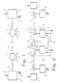
- a telecommunications line of the optical type comprises in general a station 1 for the emission of optical signals, wherein the signals 2 to be transmitted are received, usually in the form of electrical signals, and emitted in an optical form injected into an optical fibre 3, constituting the line.
- reception station 4 suitable for receiving the optical signals transmitted along the fibre, for converting them into signals of another nature, say electrical signals, and for sending such signals 5 to the reception equipment, not shown.
- the emission and reception stations are known in themselves and shall not be described further.
- line amplifiers 6 suitable for receiving the optical signal attenuated after a certain length of fibre and for emitting it after having restored it to the original level, to allow it to pass along a further fibre section, up to a new amplifier or up to the receiving station, maintaining itself to destination at a level which will allow it to be received correctly.
- a telecommunications line operating over great distances, comprises a certain number of amplifiers, in relation to the overall distance to be covered, to the fibre's attenuation, to the gain of the amplifiers and to the minimum level acceptable for the signal at reception.
- the amplifiers 6, of whatever type they may be, provide in general for the reception and/or emission of control signals, say for the activation or the check of the operation of some of their components, and, in addition, are subjected to maintenance activities for which an operator may have to communicate with the terminal emission or reception stations, or with other line amplifiers.
- the service signals may be of the same type as the communications signals and recognised by and separated from the same, or they may be introduced into the line, when all the signals are converted in an electrical form in the amplifiers or in the terminal stations, to be used as required.
- each optical amplifier 8 generically represented in the figure, there are, upstream and downstream from the same, two dichroic couplers 9, suitable for receiving in a common input the communication signals and the service signals, having wavelengths that are different and multiplexed on the same fibre and for separating at output on two outgoing fibres 9a and 9b the communication signals at one wavelength and the service signals at a different wavelength, respectively, and also suitable for sending in a single outgoing fibre the communication signals and the service signals separately injected into fibres 9a and 9b.
- the wavelength of the service signals is selected to be appreciably different from that of communication.
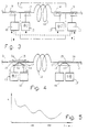
- the communication wavelength usually ranges from 1500 to 1600 nm, in an area called third window, so as to operate at the minimum of the light attenuation in silica glass fibres, as illustrated in the diagram of Fig. 6; as required for telecommunications, this allows the transmission of data at high speed, of the order of several hundred Mbit/sec, over distances of tens or hundreds of kilometres before amplification, maintaining the signals at levels sufficient for a correct final reception.
- the service signals can be transmitted at low speed, of the order of some hundreds of Kbit/sec, in particular below 300 Kbit/sec; according to the invention such service signals are then emitted at a wavelength around 1300nm, at a secondary minimum of the light attenuation curve in silica glass, called second window.
- the words around 1300 nm shall mean a wavelength in the wavelength range typical of the above mentioned second window, where there is a relatively low attenuation; the amplitude of such range depends on the specific characteristics of the line fibre used; a preferred range, for commonly produced line fibres, can be from 1200 to 1400 nm.
- the light attenuation at such wavelength is appreciably higher than at 1500-1600 nm, and would not allow the coverage of the distance between two successive amplifiers with an arrival level acceptable for the reception equipment suitable for operation at the transmission speeds used for the communication signals indicated above; but the service signals, on the other hand, transmitted at lower speeds (typically 128 Kbit/sec, can be received by very sensitive receivers and thus a wavelength around 1300 nm is acceptable for them.
- dichroic couplers such as fibres that are fused or accomplished in micro-optics, having excellent features in terms of attenuation and limited cost.
- Each dichroic coupler 9 is connected, with the corresponding outgoing fibre 9b carrying the service signals, to a respective connecting unit 10, through which the service signals leaving the coupler are received and converted into corresponding output electrical signals, and input electrical signals are converted into optical signals at the service wavelength and injected at the input into the fibre 9b to be multiplexed along the line.
- an optical signal at 1300 nm, extracted from line 3 by dichroic coupler 9, is transformed into a corresponding electrical signal, which may be used for the purposes provided for it, such as, say, service telephone communications of maintenance or control personnel of optical amplifier 8, as represented by dotted lines in Fig. 2, or for further commands or controls; in a similar manner, electrical control signals or service telephone communications can be sent along fibre 3 of the line to reach other destinations.
- the electrical signal in output from a unit 10 connected to a dichroic coupler 9, located upstream from an optical line amplifier 8, is electronically amplified, in a known manner, by a corresponding service amplifier 11 and then sent to the input of a unit 10 connected to a second dichroic coupler 9, downstream from the optical amplifier, suitable for sending the appropriately amplified service signal along the subsequent optical fibre section, up to the destination station or to a new optical amplifier.
- the service signal is amplified autonomously, at each optical amplifier of the line and can thus travel along the entire distance required and arrive at destination at a level sufficient for the purposes assigned to it.
- Fig. 3 shows in greater detail an embodiment of the invention, which shows an optical amplifier 8 which comprises an active optical fibre 12, having a suitable length, doped with a fluorescent substance, a pumping laser 13, connected to a corresponding dichroic coupler 14, suitable for sending inside the active fibre luminous energy suitable for producing a stimulated emission inside the fibre itself, which generates the requested amplification.
- an optical amplifier 8 which comprises an active optical fibre 12, having a suitable length, doped with a fluorescent substance, a pumping laser 13, connected to a corresponding dichroic coupler 14, suitable for sending inside the active fibre luminous energy suitable for producing a stimulated emission inside the fibre itself, which generates the requested amplification.
- amplifier 8 is preceded and followed by the dichroic couplers 9, connected to their respective service signals reception and transmission units 10.
- the lasers 13 and 13' are connected, as represented by the dotted lines, to units 10 and can thus receive or send control or similar signals which govern their operation.
- Fig. 4 shows a particular embodiment of the invention, in which there are two pumping lasers, 13 and 13' and each of them, together with a reception or transmission unit 10, is connected to a single three-wavelength optical coupler 15, so that the pumping laser sends the corresponding luminous energy towards the active fibre 12, while the reception and transmission unit 10 receives service signals, separate from the optical fibre 3 of the line, before they arrive at the active fibre itself and/or injects service signals into fibre 3 after the active fibre.
- each dichroic coupler 15 is in the position of allowing the communication signal Sc, at the communications wavelength (1500-1600 nm), carried by line fibre 3 to the coupler's input connection 16, to be emitted unaltered at the output connection 17, to which the amplifier's active fibre 12 is connected;
- the service signal Ss at the service wavelength (1300 nm), present at input connection 16, is addressed to the coupler's output connection 18, to which unit 10 is connected (and vice versa, a signal emitted by unit 10, carried as an input to connection 18 is sent, along the same optical path, as an output to connection 16);
- the pumping signal Sp at the pumping wavelength, is sent by pumping laser 13 or 13' as an input to connection 19 and is sent as an output to connection 17.
- Three-wavelength optical couplers having the indicated characteristics, constituted by a single monolithic element, say, of the fused fibre type, are known and their accomplishment is made easy and sufficiently inexpensive when the wavelengths to be coupled are appreciably separated one from the other: say, in combination with a communication signal wavelength around 1550 nm a service signal wavelength is used around 1300 nm, as described above and, in the case of an active amplification fibre doped with Erbium, a pumping wavelength of 980 or 530 nm.
- a wavelength may be adopted, for the service signals, other than that around 1300 nm indicated previously, accepting the signal attenuation level which corresponds to the selected wavelength.
- a different wavelength, or a different range of wavelengths may be adopted for the service signals, corresponding to a relative attenuation minimum, or in any case to a sufficiently low attenuation value, in relation to the power and to the sensitivity of the transmission and reception equipment, as long as it is sufficiently far from the range of transmission wavelengths as to allow the accomplishment of the corresponding optical couplers.
- line end stations are two points of the line itself between which the signals travel solely in an optical form, amplified where necessary by optical amplifiers of the type described above.
Abstract
Description
- The present invention relates to an optical fibre telecommunications line, provided with an independent channel for service communications.
- Communications lines, suitable for allowing the transmission of communications over great distances, in addition to the channels used for communications signals, placed at the disposal of subscribers, usually also provide for an independent channel, suitable for allowing the transmission of service communications.
- Such service signals can be of different kinds, say control or command signals for equipment located along the line, such as amplifiers or repeaters, or communications between maintenance staff, operating at a point along the line, and an intermediate or end station of the line itself.
- In an optical fibre telecommunications line, provided at regular intervals with repeaters for the amplification of the transmitted signals, one or more of the communications channels may be used for the service signals, which are accessible, for sending or receiving service signals, at each repeater, where the optical signals are detected and transformed into electrical signals, electronically amplified and once again sent towards the destination station, in an optical form.
- In such repeaters a service signal converted into an electrical form can be easily received and used for the desired purposes and in a similar manner a signal may be injected in an electric form into the repeater and then converted into an optical signal together with the other signals subjected to amplification and sent along the line.
- However, optical fibre telecommunication lines have currently proved convenient which, instead of repeaters, of an electronic type, use optical amplifiers, in a position of amplifying the signal without converting it into an electrical form.
- In such lines it is not possible for signals to be injected into or to extracted from the fibre along which they are transmitted with the known electronic equipment, because the signals are available only in an optical form, even at the amplifiers.
- The problem therefore arises of injecting into and extracting from an optical telecommunications line, possibly provided with optical amplifiers, the service signals, by operating on the signals themselves in an optical form.
- There are known devices called optical couplers, suitable for injecting into or for extracting from an optical fibre signals having a wavelength different from that of the other signals, which pass unaltered, but, in order for such couplers do operate correctly, with a complete separation between the extracted signals and the unaltered signals and with a reduced attenuation of the signals themselves, they must operate between wavelengths that are substantially different, while optical communications are accomplished in a fairly narrow range of wavelengths, where the transmission characteristics of the fibre are better.
- The object of the present invention is thus to provide an optical fibre transmission line where it is possible to inject and extract service optical signals, without having to convert the transmitted signals into an electrical form.
- The object of the present invention is an optical fibre transmission line, comprising at least one emission station and one reception station of telecommunications signals and at least one optical amplifier, characterized in that it comprises means for injecting and means for extracting optical service signals from the line's optical fibre, where said means comprise at least one emission and/or reception unit of optical service signals, suitable for receiving from the optical line and/or emitting towards the same service signals, constituted by communication or control signals electrically supplied by or taken from the unit itself, in the form of optical signals having a wavelength which is substantially different from the wavelength of the telecommunications signals, where said unit is associated with a corresponding optical coupler inserted along the line, suitable for coupling within the line fibre and/or for extracting from it the optical service signals, with the optical amplifier or with each optical amplifier there being associated at least one means for injecting or extracting optical service signals.
- Preferably the optical amplifier or each optical amplifier is associated with a means for injecting and with a means for extracting service optical signals, suitable for switching the service signals themselves along a path external to the amplifier.
- The wavelength of the service signals is substantially equal to or differs only slightly from the wavelength corresponding to a minimum of the attenuation curve of the light in the optical fibre in relation to the wavelength.
- Conveniently such wavelength of the telecommunications signals ranges substantially from 1500 to 1600 nm and the wavelength of the service signals ranges from 1200 to 1400 nm, said service signals being transmitted at a rate substantially lower than 300 Kbit/sec.
- Preferably the optical couplers are constituted by dichroic fibre couplers.
- In greater detail, in such a preferred embodiment the line optical amplifier or amplifiers are constituted by sections of active fibre, doped with fluorescent substances and by means for injecting into the sections of active fibre luminous pumping energy, having a wavelength different from the telecommunications wavelength, generated by respective pumping lasers, there being present at at least one amplifier a reception unit and an emission unit of service optical signals and corresponding optical couplers inserted along the line fibre, upstream and downstream from the optical amplifier, respectively, in the direction in which the service signals are to be sent.
- Conveniently the reception and emission units are connected together electrically, with the possible interposition of electronic amplification means, said units being suitable for receiving optical service signals from the line, for transforming them into electrical signals, for amplifying them electronically and respectively for receiving the amplified electrical signals, for converting them into optical signals at the service wavelength and for sending them along the line; the reception and emission units of the service signals comprise means for the control and command of the amplifier' s pumping laser or lasers, driven by the service signals.
- In a preferred embodiment of the invention the means for injecting luminous pumping energy into the active fibre sections of at least one optical amplifier and one optical coupler of the service signals at the amplifier itself are constituted by a single three-wavelength optical coupler.
- Greater details can be seen from the following description of the invention, with reference to the enclosed drawings, which show:
- in Fig. 1,
- a diagram of an optical fibre telecommunications line, with line amplifiers;
- in Fig. 2,
- a diagram of an optical fibre telecommunications line, with line amplifiers, provided with inputs and outputs for service communications;
- in Fig. 3,
- a diagram of an optical amplifier for a telecommunications line, provided with inputs and outputs for service channels according to the invention;
- in Fig. 4,
- a diagram of an optical amplifier for a telecommunications line, provided with inputs and outputs for service channels according to the invention, in a particular embodiment;
- in Fig. 5,
- a diagram of the curve of the light attenuation in a silica optical fibre, in relation to the wavelength of the injected light.
- As shown by Fig. 1, a telecommunications line of the optical type comprises in general a station 1 for the emission of optical signals, wherein the
signals 2 to be transmitted are received, usually in the form of electrical signals, and emitted in an optical form injected into anoptical fibre 3, constituting the line. - At the opposite end of
fibre 3, at a great distance from the emission station 1, even of the order of hundreds of kilometres, there is a reception station 4, suitable for receiving the optical signals transmitted along the fibre, for converting them into signals of another nature, say electrical signals, and for sendingsuch signals 5 to the reception equipment, not shown. - The emission and reception stations are known in themselves and shall not be described further.
- Along the
fibre 3, due to the attenuations to which the optical signal is inevitably subjected in its path along the fibre itself, there areline amplifiers 6, suitable for receiving the optical signal attenuated after a certain length of fibre and for emitting it after having restored it to the original level, to allow it to pass along a further fibre section, up to a new amplifier or up to the receiving station, maintaining itself to destination at a level which will allow it to be received correctly. - A telecommunications line, operating over great distances, comprises a certain number of amplifiers, in relation to the overall distance to be covered, to the fibre's attenuation, to the gain of the amplifiers and to the minimum level acceptable for the signal at reception.
- The
amplifiers 6, of whatever type they may be, provide in general for the reception and/or emission of control signals, say for the activation or the check of the operation of some of their components, and, in addition, are subjected to maintenance activities for which an operator may have to communicate with the terminal emission or reception stations, or with other line amplifiers. - In all these cases it is thus required to introduce into the communication line further signals 7, which may be received and injected at any line amplifier or at the terminal stations.
- In the case wherein the line amplifiers are repeaters, which thus receive optical signals travelling on the line, convert them into an electrical form, amplify them electronically and retransmit them in an optical form into the subsequent line section, the service signals may be of the same type as the communications signals and recognised by and separated from the same, or they may be introduced into the line, when all the signals are converted in an electrical form in the amplifiers or in the terminal stations, to be used as required.
- In optical fibre telecommunications lines there is, however, convenient use for amplifiers of the optical type, wherein the signals are amplified while remaining in an optical form; in such cases, therefore, it is not possible by electronic means for separating the service signals from the communication signals travelling in the same fibre without interrupting the fibre itself.
- For such purpose according to the invention, as illustrated by Fig. 2, at each
optical amplifier 8, generically represented in the figure, there are, upstream and downstream from the same, twodichroic couplers 9, suitable for receiving in a common input the communication signals and the service signals, having wavelengths that are different and multiplexed on the same fibre and for separating at output on twooutgoing fibres 9a and 9b the communication signals at one wavelength and the service signals at a different wavelength, respectively, and also suitable for sending in a single outgoing fibre the communication signals and the service signals separately injected intofibres 9a and 9b. - Similar dichroic couplers are present at the emission and reception stations 1, 4.
- In order to accomplish the separation between the signals by means of dichroic couplers, the wavelength of the service signals is selected to be appreciably different from that of communication.
- The communication wavelength usually ranges from 1500 to 1600 nm, in an area called third window, so as to operate at the minimum of the light attenuation in silica glass fibres, as illustrated in the diagram of Fig. 6; as required for telecommunications, this allows the transmission of data at high speed, of the order of several hundred Mbit/sec, over distances of tens or hundreds of kilometres before amplification, maintaining the signals at levels sufficient for a correct final reception.
- The service signals, on the other hand, in view of their characteristics, can be transmitted at low speed, of the order of some hundreds of Kbit/sec, in particular below 300 Kbit/sec; according to the invention such service signals are then emitted at a wavelength around 1300nm, at a secondary minimum of the light attenuation curve in silica glass, called second window.
- In the following text, the words around 1300 nm shall mean a wavelength in the wavelength range typical of the above mentioned second window, where there is a relatively low attenuation; the amplitude of such range depends on the specific characteristics of the line fibre used; a preferred range, for commonly produced line fibres, can be from 1200 to 1400 nm.
- The light attenuation at such wavelength is appreciably higher than at 1500-1600 nm, and would not allow the coverage of the distance between two successive amplifiers with an arrival level acceptable for the reception equipment suitable for operation at the transmission speeds used for the communication signals indicated above; but the service signals, on the other hand, transmitted at lower speeds (typically 128 Kbit/sec, can be received by very sensitive receivers and thus a wavelength around 1300 nm is acceptable for them.
- This makes it possible to use commercially produced dichroic couplers, such as fibres that are fused or accomplished in micro-optics, having excellent features in terms of attenuation and limited cost.
- Each
dichroic coupler 9 is connected, with the correspondingoutgoing fibre 9b carrying the service signals, to a respective connectingunit 10, through which the service signals leaving the coupler are received and converted into corresponding output electrical signals, and input electrical signals are converted into optical signals at the service wavelength and injected at the input into thefibre 9b to be multiplexed along the line. - In this way an optical signal, at 1300 nm, extracted from
line 3 bydichroic coupler 9, is transformed into a corresponding electrical signal, which may be used for the purposes provided for it, such as, say, service telephone communications of maintenance or control personnel ofoptical amplifier 8, as represented by dotted lines in Fig. 2, or for further commands or controls; in a similar manner, electrical control signals or service telephone communications can be sent alongfibre 3 of the line to reach other destinations. - To allow the service signals to reach amplifiers or terminal stations located at a great distance from the place at which the signal is emitted, along a fibre having several optical amplifiers, the electrical signal in output from a
unit 10 connected to adichroic coupler 9, located upstream from anoptical line amplifier 8, is electronically amplified, in a known manner, by acorresponding service amplifier 11 and then sent to the input of aunit 10 connected to a seconddichroic coupler 9, downstream from the optical amplifier, suitable for sending the appropriately amplified service signal along the subsequent optical fibre section, up to the destination station or to a new optical amplifier. - In this way the service signal is amplified autonomously, at each optical amplifier of the line and can thus travel along the entire distance required and arrive at destination at a level sufficient for the purposes assigned to it.
- Fig. 3 shows in greater detail an embodiment of the invention, which shows an
optical amplifier 8 which comprises an activeoptical fibre 12, having a suitable length, doped with a fluorescent substance, apumping laser 13, connected to a correspondingdichroic coupler 14, suitable for sending inside the active fibre luminous energy suitable for producing a stimulated emission inside the fibre itself, which generates the requested amplification. - Preferably, but not necessarily, there can also be a second pumping laser 13' and a corresponding dichroic coupler 14', arranged at the opposite end of the
active fibre 12 with respect tocoupler 14 and mirror oriented, with the purpose of enhancing the pumping power inside the active fibre and/or constituting a pumping means of the active fibre held in reserve in case of malfunction of thefirst pumping laser 13. - In must in any case be observed that the possible presence of the second pumping laser 13' and of the coupler 14' is substantially non-influent, in this embodiment, for the purpose of transmitting service signals along the optical line according to the present invention.
- As already illustrated with reference to Fig. 2,
amplifier 8 is preceded and followed by thedichroic couplers 9, connected to their respective service signals reception andtransmission units 10. Thelasers 13 and 13' are connected, as represented by the dotted lines, tounits 10 and can thus receive or send control or similar signals which govern their operation. - Fig. 4 shows a particular embodiment of the invention, in which there are two pumping lasers, 13 and 13' and each of them, together with a reception or
transmission unit 10, is connected to a single three-wavelengthoptical coupler 15, so that the pumping laser sends the corresponding luminous energy towards theactive fibre 12, while the reception andtransmission unit 10 receives service signals, separate from theoptical fibre 3 of the line, before they arrive at the active fibre itself and/or injects service signals intofibre 3 after the active fibre. - In greater detail, as schematically indicated in Fig. 4 by the arrows designated with Sc, Ss, Sp, respectively, each
dichroic coupler 15 is in the position of allowing the communication signal Sc, at the communications wavelength (1500-1600 nm), carried byline fibre 3 to the coupler'sinput connection 16, to be emitted unaltered at theoutput connection 17, to which the amplifier'sactive fibre 12 is connected; the service signal Ss, at the service wavelength (1300 nm), present atinput connection 16, is addressed to the coupler's output connection 18, to whichunit 10 is connected (and vice versa, a signal emitted byunit 10, carried as an input to connection 18 is sent, along the same optical path, as an output to connection 16); the pumping signal Sp, at the pumping wavelength, is sent by pumpinglaser 13 or 13' as an input toconnection 19 and is sent as an output toconnection 17. - Three-wavelength optical couplers having the indicated characteristics, constituted by a single monolithic element, say, of the fused fibre type, are known and their accomplishment is made easy and sufficiently inexpensive when the wavelengths to be coupled are appreciably separated one from the other: say, in combination with a communication signal wavelength around 1550 nm a service signal wavelength is used around 1300 nm, as described above and, in the case of an active amplification fibre doped with Erbium, a pumping wavelength of 980 or 530 nm.
- Such an accomplishment offers the considerable advantage of accomplishing, with the same component, both the sending of the pumping energy in the amplification fibre, and the extraction or the sending of the service signals in the line fibre, simplifying the amplifier structure and especially reducing the number of junctions between fibres and couplers, each of which is the cause of attenuation for the transmitted signal.
- In case the use of the second pumping laser 13' is not desired, in place of one of the three-
wavelength couplers 15, to which such laser should have been connected, it is possible to use adichroic coupler 9, as described previously, merely for the connection of the service reception andtransmission unit 10. - Although the injection into and the extraction from the optical line of the service signals is conveniently executed at the line's end stations and at the line amplifiers, as described previously, it is possible to introduce dichroic couplers and service signal reception and transmission stations at any other position of the optical fibre line where its need may be felt.
- In the case of particular requirements of the line or in the structure of the couplers, a wavelength may be adopted, for the service signals, other than that around 1300 nm indicated previously, accepting the signal attenuation level which corresponds to the selected wavelength.
- In addition, within the scope of the present invention, in the presence of fibres having particular transmission characteristics, instead of the wavelength around 1300 nm, in the sense previously defined, a different wavelength, or a different range of wavelengths, may be adopted for the service signals, corresponding to a relative attenuation minimum, or in any case to a sufficiently low attenuation value, in relation to the power and to the sensitivity of the transmission and reception equipment, as long as it is sufficiently far from the range of transmission wavelengths as to allow the accomplishment of the corresponding optical couplers.
- For the purpose of the present invention it is intended that line end stations are two points of the line itself between which the signals travel solely in an optical form, amplified where necessary by optical amplifiers of the type described above.
- Many variants can be introduced in the future, without going beyond the scope of the present invention in its general characteristics.
Claims (9)
- Optical fibre transmission line, comprising at least one emission station (1) and one reception station (4) of telecommunications signals and at least one optical amplifier (6, 8), characterized in that it comprises means (9, 10) for injecting and means (9, 10) for extracting optical service signals from the line' s optical fibre (3), where said means comprise at least one emission and/or reception unit (10) of optical service signals, suitable for receiving from the optical line and/or emitting towards the same service signals, constituted by communication or control signals electrically supplied by or taken from the unit itself, in the form of optical signals having a wavelength which is substantially different from the wavelength of the telecommunications signals, where said unit (10) is associated with a corresponding optical coupler (9) inserted along the line, suitable for coupling within the line fibre (3) and/or for extracting from it the optical service signals, with the optical amplifier (6, 8) or with each optical amplifier there being associated at least one means (9, 10) for injecting or extracting optical service signals.
- Optical fibre transmission line according to claim 1, characterized in that the optical amplifier (6, 8) or each optical amplifier is associated with a means (9, 10) for injecting and with a means (9, 10) for extracting optical service signals, suitable for switching the service signals themselves along a path external to the amplifier (8).
- Optical fibre transmission line according to claim 1, characterized in that the wavelength of the service signals is substantially equal to or differs only slightly from the wavelength corresponding to a minimum of the attenuation curve of the light in the optical fibre in relation to the wavelength.
- Optical fibre transmission line according to claim 1, characterized in that the wavelength of the telecommunications signals ranges substantially from 1500 to 1600 nm and the wavelength of the service signals ranges from 1200 to 1400 nm, said service signals being transmitted at a rate substantially lower than 300 Kbit/sec.
- Optical fibre transmission line according to claim 1, characterized in that the optical couplers (9) are constituted by by dichroic fibre couplers.
- Optical fibre transmission line according to claim 2, characterized in that the line optical amplifier (6, 8) or amplifiers are constituted by sections of active fibre (12), doped with fluorescent substances and by means (14) for injecting into the sections of active fibre (12) luminous pumping energy, having a wavelength different from the telecommunications wavelength, generated by respective pumping lasers (13), there being present at at least one amplifier a reception unit (10) and an emission unit (10) of service optical signals and corresponding optical couplers (9) inserted along the line fibre (3), upstream and downstream from the optical amplifier (8), respectively, in the direction in which the service signals are to be sent.
- Optical fibre transmission line according to claim 6, characterized in that the reception and emission units (10) are connected together electrically, with the possible interposition of electronic amplification means (11), said units being suitable for receiving optical service signals from the line (3), for transforming them into electrical signals, for amplifying them electronically and respectively for receiving the amplified electrical signals, for converting them into optical signals at the service wavelength and for sending them along the line.
- Optical fibre transmission line according to claim 6, characterized in that the reception and emission units (10) of the service signals comprise means for the control and command of the amplifier' s pumping laser or lasers (13), driven by the service signals.
- Optical fibre transmission line according to claim 6, characterized in that the means (15) for injecting luminous pumping energy into the active fibre sections of at least one optical amplifier and one optical coupler of the service signals at the amplifier itself are constituted by a single three-wavelength optical coupler (15).
Applications Claiming Priority (2)
| Application Number | Priority Date | Filing Date | Title |
|---|---|---|---|
| IT1918690 | 1990-01-30 | ||
| IT01918690A IT1238032B (en) | 1990-01-30 | 1990-01-30 | FIBER OPTIC TELECOMMUNICATION LINE WITH SEPARATE SERVICE CHANNELS |
Publications (4)
| Publication Number | Publication Date |
|---|---|
| EP0440276A2 true EP0440276A2 (en) | 1991-08-07 |
| EP0440276A3 EP0440276A3 (en) | 1992-07-29 |
| EP0440276B1 EP0440276B1 (en) | 1996-02-28 |
| EP0440276B2 EP0440276B2 (en) | 2003-10-08 |
Family
ID=11155629
Family Applications (1)
| Application Number | Title | Priority Date | Filing Date |
|---|---|---|---|
| EP91200067A Expired - Lifetime EP0440276B2 (en) | 1990-01-30 | 1991-01-15 | Optical fibre telecommunications line with separate service channels |
Country Status (25)
| Country | Link |
|---|---|
| US (1) | US5113459C1 (en) |
| EP (1) | EP0440276B2 (en) |
| JP (1) | JP3218047B2 (en) |
| KR (1) | KR100216858B1 (en) |
| CN (1) | CN1025646C (en) |
| AR (1) | AR243704A1 (en) |
| AT (1) | ATE134808T1 (en) |
| AU (1) | AU647063B2 (en) |
| BR (1) | BR9100049A (en) |
| CA (1) | CA2034915C (en) |
| CZ (1) | CZ282145B6 (en) |
| DE (1) | DE69117312T3 (en) |
| DK (1) | DK0440276T3 (en) |
| ES (1) | ES2085951T3 (en) |
| FI (1) | FI102650B (en) |
| HK (1) | HK201396A (en) |
| HU (1) | HU208599B (en) |
| IE (1) | IE74686B1 (en) |
| IT (1) | IT1238032B (en) |
| MY (1) | MY104614A (en) |
| NO (1) | NO303256B1 (en) |
| NZ (1) | NZ236897A (en) |
| PL (1) | PL167324B1 (en) |
| PT (1) | PT96594B (en) |
| RU (1) | RU2081515C1 (en) |
Cited By (24)
| Publication number | Priority date | Publication date | Assignee | Title |
|---|---|---|---|---|
| EP0449475A2 (en) * | 1990-03-26 | 1991-10-02 | AT&T Corp. | Telemetry for optical fiber amplifier repeater |
| EP0450524A2 (en) * | 1990-04-03 | 1991-10-09 | Alcatel SEL Aktiengesellschaft | Optical transmission system with a fiber optic amplifier |
| EP0485813A2 (en) * | 1990-11-15 | 1992-05-20 | Alcatel SEL Aktiengesellschaft | Optical telecommunications system with optic fiber amplifier |
| GB2257320A (en) * | 1991-07-01 | 1993-01-06 | Fujitsu Ltd | An optical communication system |
| EP0530109A1 (en) * | 1991-08-30 | 1993-03-03 | France Telecom | Optical communication system using semi-conductor traveling wave optical amplifiers |
| FR2696302A1 (en) * | 1992-09-28 | 1994-04-01 | Cit Alcatel | Fibre=optics amplifier for long distance telecommunications - has amplifier module extracting interrogation signal, mixing with pump signal and injecting supervisory signal |
| EP0617527A1 (en) * | 1993-03-23 | 1994-09-28 | Nortel Networks Corporation | Transmission systems incorporating optical amplifiers |
| DE4333367A1 (en) * | 1993-09-30 | 1995-04-06 | Ant Nachrichtentech | Sender and receiver for an optical communication system |
| EP0650272A1 (en) * | 1993-10-25 | 1995-04-26 | AT&T Corp. | In-line two-stage erbium doped fiber amplifier system |
| EP0848511A2 (en) * | 1996-12-10 | 1998-06-17 | Robert Bosch Gmbh | Apparatus for coupling of optical signals to and from two transmission channels |
| US5812289A (en) * | 1992-04-08 | 1998-09-22 | Hitachi, Ltd. | Optical repeater and optical transmitter |
| US5844706A (en) * | 1993-09-30 | 1998-12-01 | Robert Bosch Gmbh | Fibre-optic communications-transmission method and intermediate repeater for use in the method |
| WO1998054863A1 (en) * | 1997-05-27 | 1998-12-03 | Ciena Corporation | Span management system for wavelength division multiplexed network |
| EP0931370A1 (en) * | 1996-10-10 | 1999-07-28 | Tyco Submarine Systems Ltd. | Lossless optical transmission system architecture |
| WO2000003460A2 (en) * | 1998-05-22 | 2000-01-20 | Ciena Corporation | Fiber optic amplifier |
| EP0777345A3 (en) * | 1995-11-30 | 2000-08-02 | Kokusai Denshin Denwa Kabushiki Kaisha | Surveillance method of optical amplifier-repeater transmission system |
| WO2000064079A1 (en) * | 1999-04-15 | 2000-10-26 | Nortel Networks Limited | A highly scalable modular optical amplifier based subsystem |
| WO2001031826A1 (en) * | 1999-10-28 | 2001-05-03 | Marconi Communications Limited | Optical add-drop filter |
| US6266169B1 (en) | 1992-04-08 | 2001-07-24 | Hitachi, Ltd. | Optical transmission equipment which transmits an amplified optical data signal and an optical surveillance signal |
| EP0970572B1 (en) * | 1997-03-27 | 2003-01-22 | Robert Bosch Gmbh | Optical transmission device and method for checking transmission in an optical transmission device |
| US6748342B1 (en) * | 1999-04-20 | 2004-06-08 | Nokia Corporation | Method and monitoring device for monitoring the quality of data transmission over analog lines |
| US6757098B2 (en) * | 1999-04-15 | 2004-06-29 | Nortel Network Limited | Highly scalable modular optical amplifier based subsystem |
| US6947668B1 (en) | 1998-02-20 | 2005-09-20 | Robert Bosch Gmbh | Method for transferring utility optical signals and optical-line network |
| EP1439653A3 (en) * | 1997-05-27 | 2007-09-19 | Ciena Corporation | Span management system for wavelength division multiplexed network |
Families Citing this family (27)
| Publication number | Priority date | Publication date | Assignee | Title |
|---|---|---|---|---|
| DE4019225A1 (en) * | 1990-06-15 | 1991-12-19 | Standard Elektrik Lorenz Ag | OPTICAL SWITCHING ELEMENT |
| IT1247844B (en) * | 1991-03-29 | 1995-01-02 | Pirelli Cavi S P A Dir Proprie | OPTICAL FIBER TELECOMMUNICATION LINE WITH OPTICAL AMPLIFIERS, EQUIPPED WITH PROTECTIVE MEANS ABLE TO INTERRUPT THE LIGHT EMISSION IN THE ENTIRE LINE IN THE PRESENCE OF AN INTERRUPTION OF THE OPTICAL FIBER AND TO AUTOMATICALLY REACTIVATE IT TO RESTORE ITS CONTACT |
| IT1274368B (en) * | 1995-03-28 | 1997-07-17 | Pirelli Cavi Spa | OPTICAL TELECOMMUNICATION METHOD WITH SERVICE CHANNEL TRANSMISSION AND RECEPTION |
| US5532864A (en) * | 1995-06-01 | 1996-07-02 | Ciena Corporation | Optical monitoring channel for wavelength division multiplexed optical communication system |
| JPH09321739A (en) * | 1996-05-29 | 1997-12-12 | Nec Corp | Optical amplifier repeating transmission system |
| SE9702688D0 (en) * | 1997-07-11 | 1997-07-11 | Ericsson Telefon Ab L M | A method and system for interconnicting ring networks |
| SE9702685D0 (en) * | 1997-07-11 | 1997-07-11 | Ericsson Telefon Ab L M | Self-healing ring network and a method for fault detection and rectifying |
| US6111675A (en) * | 1997-08-27 | 2000-08-29 | Mciworldcom, Inc. | System and method for bi-directional transmission of telemetry service signals using a single fiber |
| US6388782B1 (en) | 1998-06-01 | 2002-05-14 | Sarnoff Corporation | Multi-wavelength dense wavelength division multiplexed optical switching systems |
| US6014237A (en) * | 1998-06-01 | 2000-01-11 | Sarnoff Corporation | Multiwavelength mode-locked dense wavelength division multiplexed optical communication systems |
| US6411407B1 (en) | 1998-09-17 | 2002-06-25 | Alcatel | Method for providing a bidirectional optical supervisory channel |
| US6192058B1 (en) | 1998-09-18 | 2001-02-20 | Sarnoff Corporation | Multiwavelength actively mode-locked external cavity semiconductor laser |
| US6359729B1 (en) | 1998-11-17 | 2002-03-19 | Corvis Corporation | Optical communication system and component control architectures and methods |
| JP3605629B2 (en) * | 1998-12-15 | 2004-12-22 | 富士通株式会社 | Light source redundancy switching method and wavelength division multiplex transmission apparatus by the method |
| US6400863B1 (en) * | 1999-06-11 | 2002-06-04 | General Instrument | Monitoring system for a hybrid fiber cable network |
| US7286756B1 (en) | 2001-05-15 | 2007-10-23 | Cisco Technology, Inc. | DWDM system with IP telephony provisioning at remote locations |
| US20030063345A1 (en) * | 2001-10-01 | 2003-04-03 | Dan Fossum | Wayside user communications over optical supervisory channel |
| US7394981B2 (en) * | 2002-03-28 | 2008-07-01 | Manifold Robert H | Optical communication management systems |
| US7489867B1 (en) | 2002-05-06 | 2009-02-10 | Cisco Technology, Inc. | VoIP service over an ethernet network carried by a DWDM optical supervisory channel |
| US20040047295A1 (en) * | 2002-08-20 | 2004-03-11 | Morreale Jay P. | Method and apparatus for providing a common optical line monitoring and service channel over an WDM optical transmission system |
| US7171122B1 (en) | 2002-09-19 | 2007-01-30 | Wellhead Patent, Llc | Fiberoptic data telecommunication system architecture |
| JP4707399B2 (en) * | 2004-07-30 | 2011-06-22 | 富士通株式会社 | Optical add / drop device |
| JP4602739B2 (en) * | 2004-11-01 | 2010-12-22 | 昭和電線ケーブルシステム株式会社 | WDM transmission system |
| JP4840027B2 (en) | 2006-08-28 | 2011-12-21 | 日本電気株式会社 | Station side optical network termination device and optical communication system |
| JP4973491B2 (en) * | 2007-12-26 | 2012-07-11 | 富士通株式会社 | Optical transmission apparatus and optical communication system |
| CN103649673A (en) * | 2011-04-15 | 2014-03-19 | 法罗技术股份有限公司 | Enhanced position detector in laser tracker |
| JP2015174208A (en) * | 2014-03-18 | 2015-10-05 | セイコーエプソン株式会社 | robot |
Citations (8)
| Publication number | Priority date | Publication date | Assignee | Title |
|---|---|---|---|---|
| US4406919A (en) * | 1980-07-22 | 1983-09-27 | Siemens Aktiengesellschaft | Method and apparatus for monitoring intermediate regenerative repeaters |
| FR2546012A1 (en) * | 1983-05-11 | 1984-11-16 | Thomson Csf | Method of two-way transmission of data by optical fibre over a serial bus and terminal device connected to this bus in order to implement this method |
| AU7836887A (en) * | 1986-09-20 | 1988-03-24 | Alcatel N.V. | A two way optical system |
| US4886334A (en) * | 1987-09-01 | 1989-12-12 | Nec Corporation | Optical amplifying repeater |
| NL8801590A (en) * | 1988-06-22 | 1990-01-16 | Nederland Ptt | OPTICAL NETWORK WITH TRANSMISSION, MERGING RESP. SEPARATION OF INFORMATION AND CONTROL SIGNALS AND ROUTING ARE PLACED IN THE OPTICAL DOMAIN. |
| DE3907497A1 (en) * | 1989-03-08 | 1990-09-13 | Standard Elektrik Lorenz Ag | OPTICAL MESSAGE TRANSMISSION SYSTEM FOR THE SUBSCRIBER AREA |
| DE3913300A1 (en) * | 1989-04-22 | 1990-10-25 | Standard Elektrik Lorenz Ag | OPTICAL MESSAGE TRANSMISSION SYSTEM FOR THE PARTICIPANT CONNECTION AREA |
| EP0414333A2 (en) * | 1989-08-25 | 1991-02-27 | ANT Nachrichtentechnik GmbH | Optical fibre data network |
Family Cites Families (7)
| Publication number | Priority date | Publication date | Assignee | Title |
|---|---|---|---|---|
| US4276656A (en) * | 1979-03-19 | 1981-06-30 | Honeywell Information Systems Inc. | Apparatus and method for replacement of a parallel, computer-to-peripheral wire link with a serial optical link |
| US4781427A (en) * | 1985-09-19 | 1988-11-01 | The Mitre Corporation | Active star centered fiber optic local area network |
| US5054896A (en) * | 1988-12-19 | 1991-10-08 | Infinity Photo-Optical Corporation | Continuously focusable microscope incorporating an afocal variator optical system |
| GB2218534B (en) * | 1988-05-14 | 1992-03-25 | Stc Plc | Active optical fibre star coupler |
| DE3819445A1 (en) * | 1988-06-08 | 1989-12-14 | Standard Elektrik Lorenz Ag | OPTICAL NEWS TRANSMISSION SYSTEM, ESPECIALLY IN THE SUBSCRIBER CONNECTION AREA |
| US4878726A (en) * | 1988-11-10 | 1989-11-07 | American Telephone And Telegraph Company | Optical transmission system |
| US4911515A (en) * | 1988-12-22 | 1990-03-27 | Northern Telecom Limited | Optical fiber communications system with optical fiber monitoring |
-
1990
- 1990-01-30 IT IT01918690A patent/IT1238032B/en active IP Right Grant
-
1991
- 1991-01-04 AU AU68661/91A patent/AU647063B2/en not_active Expired
- 1991-01-15 EP EP91200067A patent/EP0440276B2/en not_active Expired - Lifetime
- 1991-01-15 ES ES91200067T patent/ES2085951T3/en not_active Expired - Lifetime
- 1991-01-15 AT AT91200067T patent/ATE134808T1/en not_active IP Right Cessation
- 1991-01-15 DE DE69117312T patent/DE69117312T3/en not_active Expired - Lifetime
- 1991-01-15 DK DK91200067.6T patent/DK0440276T3/en active
- 1991-01-18 MY MYPI91000080A patent/MY104614A/en unknown
- 1991-01-23 CZ CS91147A patent/CZ282145B6/en not_active IP Right Cessation
- 1991-01-24 NZ NZ236897A patent/NZ236897A/en unknown
- 1991-01-24 CA CA002034915A patent/CA2034915C/en not_active Expired - Lifetime
- 1991-01-28 AR AR91318926A patent/AR243704A1/en active
- 1991-01-29 HU HU91315A patent/HU208599B/en not_active IP Right Cessation
- 1991-01-29 IE IE29791A patent/IE74686B1/en not_active IP Right Cessation
- 1991-01-29 KR KR1019910001470A patent/KR100216858B1/en not_active IP Right Cessation
- 1991-01-29 PT PT96594A patent/PT96594B/en not_active IP Right Cessation
- 1991-01-29 NO NO910329A patent/NO303256B1/en not_active IP Right Cessation
- 1991-01-29 FI FI910420A patent/FI102650B/en active IP Right Grant
- 1991-01-29 PL PL91288879A patent/PL167324B1/en unknown
- 1991-01-29 US US07647141 patent/US5113459C1/en not_active Expired - Lifetime
- 1991-01-30 JP JP00994791A patent/JP3218047B2/en not_active Expired - Lifetime
- 1991-01-30 RU SU914894352A patent/RU2081515C1/en active
- 1991-01-30 BR BR919100049A patent/BR9100049A/en not_active IP Right Cessation
- 1991-01-30 CN CN91100536A patent/CN1025646C/en not_active Expired - Fee Related
-
1996
- 1996-11-07 HK HK201396A patent/HK201396A/en not_active IP Right Cessation
Patent Citations (8)
| Publication number | Priority date | Publication date | Assignee | Title |
|---|---|---|---|---|
| US4406919A (en) * | 1980-07-22 | 1983-09-27 | Siemens Aktiengesellschaft | Method and apparatus for monitoring intermediate regenerative repeaters |
| FR2546012A1 (en) * | 1983-05-11 | 1984-11-16 | Thomson Csf | Method of two-way transmission of data by optical fibre over a serial bus and terminal device connected to this bus in order to implement this method |
| AU7836887A (en) * | 1986-09-20 | 1988-03-24 | Alcatel N.V. | A two way optical system |
| US4886334A (en) * | 1987-09-01 | 1989-12-12 | Nec Corporation | Optical amplifying repeater |
| NL8801590A (en) * | 1988-06-22 | 1990-01-16 | Nederland Ptt | OPTICAL NETWORK WITH TRANSMISSION, MERGING RESP. SEPARATION OF INFORMATION AND CONTROL SIGNALS AND ROUTING ARE PLACED IN THE OPTICAL DOMAIN. |
| DE3907497A1 (en) * | 1989-03-08 | 1990-09-13 | Standard Elektrik Lorenz Ag | OPTICAL MESSAGE TRANSMISSION SYSTEM FOR THE SUBSCRIBER AREA |
| DE3913300A1 (en) * | 1989-04-22 | 1990-10-25 | Standard Elektrik Lorenz Ag | OPTICAL MESSAGE TRANSMISSION SYSTEM FOR THE PARTICIPANT CONNECTION AREA |
| EP0414333A2 (en) * | 1989-08-25 | 1991-02-27 | ANT Nachrichtentechnik GmbH | Optical fibre data network |
Non-Patent Citations (14)
| Title |
|---|
| Blank L.C. et al: 'Optical Time Domain Reflectometry on Optical Amplifier Systems', Journal of Lightwave Technology, Vol.7, N°10, October 1989 * |
| Breitbandverteilnetze der Deutschen Bundespost, 2. }berarbeitete und erweiterte Auflage, herausgegeben von Dipl. Ing Hans Stekle * |
| Cox J.D. et al: 'First Field Demonstation Of In-Service Fault Location/Supervisory Using Optical Time Domain Reflectometry', Electronics Letters 18/1/90, Vol. 26, N°2 * |
| Delzenne M. et al: Supervision of optical CATV trunk networks, Commutation & Transmission, N°3, 1989 * |
| Ellis A.D. et al: 'Supervisory System For Cadscaded Semiconductor Laser Amplifier Repeaters', Electronic Letters 2/3/89, Vol 25, N°5 * |
| IEEE TRANSACTIONS ON COMMUNICATION TECHNOLOGY. vol. COM35, no. 4, April 1987, NEW YORK US pages 419 - 426; S.S.WAGNER: 'Optical Amplifier Applications in Fiber Optic Local Networks' * |
| Miniscalco M.J.; Andrews L.J.: 'Fiber Optic Lasers and Amplifiers for the Near-Infrared', Materials, Science Forum Vols. 32-33 1988 pp 501-510, Copyright Trans Tech Publications, Switzerland * |
| Neues LWL-system }bertr{gt 140-Mbit/s-Signale, Telcom report 9 (1986), Heft 5, Seiten 293-301 * |
| Proceedings IEEE Global Telecommunication Conference, vol 1, 27/11/89 Dallas US Pages 1-9 * |
| Senior J.M.: 'Optical Fiber Communication-Principles and Practice', Prentice/Hall International Inc. London 1985 * |
| Settembre M. et al: "Gain compression in fibre amplifiers in presence of ESA" ECOC 1989, Sept. 10-14, 1989 Gothenburg (SE) vol.1, TuP-15, Pages 502-505 * |
| Verfahren f}r schmalbandige R}ckkan{le in Breitbandverteilnetzen, von Rudolf Scholz, Universit{t Stuttgart * |
| Wagner S.S.; Kobrinski H.: IEEE Communication Magazine, March 1989 pages 22-29 * |
| Winzer G.: Journal of Lightway Tech. Vol LT-2, N°. 4 August 1894, pages 369-378 * |
Cited By (48)
| Publication number | Priority date | Publication date | Assignee | Title |
|---|---|---|---|---|
| EP0449475A3 (en) * | 1990-03-26 | 1992-10-07 | American Telephone And Telegraph Company | Telemetry for optical fiber amplifier repeater |
| EP0449475A2 (en) * | 1990-03-26 | 1991-10-02 | AT&T Corp. | Telemetry for optical fiber amplifier repeater |
| EP0450524A2 (en) * | 1990-04-03 | 1991-10-09 | Alcatel SEL Aktiengesellschaft | Optical transmission system with a fiber optic amplifier |
| EP0450524A3 (en) * | 1990-04-03 | 1992-09-16 | Standard Elektrik Lorenz Aktiengesellschaft | Optical transmission system with a fiber optic amplifier |
| US5285306A (en) * | 1990-11-15 | 1994-02-08 | Alcatel N.V. | Optical communication system with a fiber optic amplifier |
| EP0485813A3 (en) * | 1990-11-15 | 1992-09-23 | Standard Elektrik Lorenz Aktiengesellschaft | Optical telecommunications system with optic fiber amplifier |
| EP0485813A2 (en) * | 1990-11-15 | 1992-05-20 | Alcatel SEL Aktiengesellschaft | Optical telecommunications system with optic fiber amplifier |
| GB2257320A (en) * | 1991-07-01 | 1993-01-06 | Fujitsu Ltd | An optical communication system |
| GB2257320B (en) * | 1991-07-01 | 1995-03-08 | Fujitsu Ltd | An optical communication system |
| US5311347A (en) * | 1991-07-01 | 1994-05-10 | Fujitsu Limited | Optical communication system with automatic gain control |
| EP0530109A1 (en) * | 1991-08-30 | 1993-03-03 | France Telecom | Optical communication system using semi-conductor traveling wave optical amplifiers |
| FR2680928A1 (en) * | 1991-08-30 | 1993-03-05 | France Telecom | OPTICAL COMMUNICATION SYSTEM USING PROGRESSIVE WAVE SEMICONDUCTOR OPTICAL AMPLIFIERS. |
| US5515193A (en) * | 1991-08-30 | 1996-05-07 | France Telecom Etablissement Autonome De Droit Public | Optical communications system using travelling wave semiconductor optical amplifiers |
| US6266169B1 (en) | 1992-04-08 | 2001-07-24 | Hitachi, Ltd. | Optical transmission equipment which transmits an amplified optical data signal and an optical surveillance signal |
| US6018405A (en) * | 1992-04-08 | 2000-01-25 | Hitachi, Ltd. | Optical transmission equipment which transmits an amplified optical data signal and an optical surveillance signal |
| US7167652B2 (en) | 1992-04-08 | 2007-01-23 | Hitachi, Ltd | Optical transmission system constructing method and system |
| US6728489B2 (en) | 1992-04-08 | 2004-04-27 | Hitachi, Ltd. | Optical transmission system constructing method and system |
| US7292785B2 (en) | 1992-04-08 | 2007-11-06 | Hitachi, Ltd. | Optical transmission system constructing method and system |
| US5812289A (en) * | 1992-04-08 | 1998-09-22 | Hitachi, Ltd. | Optical repeater and optical transmitter |
| US5875046A (en) * | 1992-04-08 | 1999-02-23 | Hitachi, Ltd. | Optical repeater and optical transmitter |
| FR2696302A1 (en) * | 1992-09-28 | 1994-04-01 | Cit Alcatel | Fibre=optics amplifier for long distance telecommunications - has amplifier module extracting interrogation signal, mixing with pump signal and injecting supervisory signal |
| EP0617527A1 (en) * | 1993-03-23 | 1994-09-28 | Nortel Networks Corporation | Transmission systems incorporating optical amplifiers |
| DE4333367A1 (en) * | 1993-09-30 | 1995-04-06 | Ant Nachrichtentech | Sender and receiver for an optical communication system |
| US5844706A (en) * | 1993-09-30 | 1998-12-01 | Robert Bosch Gmbh | Fibre-optic communications-transmission method and intermediate repeater for use in the method |
| US5777764A (en) * | 1993-09-30 | 1998-07-07 | Robert Bosch Gmbh | Transmission station, intermediate repeater and receiver station for a fibre-optic communications-transmission system |
| US5481399A (en) * | 1993-10-25 | 1996-01-02 | At&T Corp. | In-line two-stage erbium doped fiber amplifier system with in-band telemetry channel |
| EP0650272A1 (en) * | 1993-10-25 | 1995-04-26 | AT&T Corp. | In-line two-stage erbium doped fiber amplifier system |
| EP0777345A3 (en) * | 1995-11-30 | 2000-08-02 | Kokusai Denshin Denwa Kabushiki Kaisha | Surveillance method of optical amplifier-repeater transmission system |
| EP0931370A1 (en) * | 1996-10-10 | 1999-07-28 | Tyco Submarine Systems Ltd. | Lossless optical transmission system architecture |
| EP0931370A4 (en) * | 1996-10-10 | 2000-07-19 | Tyco Submarine Systems Ltd | Lossless optical transmission system architecture |
| EP1478060A1 (en) * | 1996-10-10 | 2004-11-17 | Tyco Telecommunications (US) Inc. | Lossless optical transmission system architecture with non-failing optical amplifiers |
| EP0848511A3 (en) * | 1996-12-10 | 2003-10-01 | Marconi Communications GmbH | Apparatus for coupling of optical signals to and from two transmission channels |
| EP0848511A2 (en) * | 1996-12-10 | 1998-06-17 | Robert Bosch Gmbh | Apparatus for coupling of optical signals to and from two transmission channels |
| EP0970572B1 (en) * | 1997-03-27 | 2003-01-22 | Robert Bosch Gmbh | Optical transmission device and method for checking transmission in an optical transmission device |
| US6583898B1 (en) | 1997-03-27 | 2003-06-24 | Robert Bosch Gmbh | Optical transmission device and method for checking transmission in an optical transmission device |
| WO1998054863A1 (en) * | 1997-05-27 | 1998-12-03 | Ciena Corporation | Span management system for wavelength division multiplexed network |
| US5978115A (en) * | 1997-05-27 | 1999-11-02 | Ciena Corporation | Span management system for wavelength division multiplexed network |
| EP1439653A3 (en) * | 1997-05-27 | 2007-09-19 | Ciena Corporation | Span management system for wavelength division multiplexed network |
| US6947668B1 (en) | 1998-02-20 | 2005-09-20 | Robert Bosch Gmbh | Method for transferring utility optical signals and optical-line network |
| USRE42095E1 (en) | 1998-02-20 | 2011-02-01 | Nola Semiconductor Llc | Method for transferring utility optical signals and optical-line network |
| WO2000003460A2 (en) * | 1998-05-22 | 2000-01-20 | Ciena Corporation | Fiber optic amplifier |
| WO2000003460A3 (en) * | 1998-05-22 | 2000-04-20 | Ciena Corp | Fiber optic amplifier |
| WO2000064079A1 (en) * | 1999-04-15 | 2000-10-26 | Nortel Networks Limited | A highly scalable modular optical amplifier based subsystem |
| US6757098B2 (en) * | 1999-04-15 | 2004-06-29 | Nortel Network Limited | Highly scalable modular optical amplifier based subsystem |
| US6236499B1 (en) | 1999-04-15 | 2001-05-22 | Nortel Networks Limited | Highly scalable modular optical amplifier based subsystem |
| US6748342B1 (en) * | 1999-04-20 | 2004-06-08 | Nokia Corporation | Method and monitoring device for monitoring the quality of data transmission over analog lines |
| WO2001031826A1 (en) * | 1999-10-28 | 2001-05-03 | Marconi Communications Limited | Optical add-drop filter |
| EP1246378A3 (en) * | 2001-03-27 | 2005-06-22 | Nortel Networks Limited | A modular bidirectional optical amplification system |
Also Published As
Similar Documents
| Publication | Publication Date | Title |
|---|---|---|
| EP0440276B1 (en) | Optical fibre telecommunications line with separate service channels | |
| US5321707A (en) | Remote pumping for active optical devices | |
| JP4898845B2 (en) | Bidirectional optical amplifier device | |
| US7103275B2 (en) | Optical transmission system | |
| EP2333991B1 (en) | Bidirectional optical amplifier | |
| EP1804400B1 (en) | An optical transmission system and a method of amplification | |
| US5005937A (en) | Optical branching equipment and optical network using the same | |
| EP0532230A1 (en) | Optical amplifiers having pump redundancy | |
| CN1075298C (en) | Optical network | |
| JP2001526494A (en) | Method and apparatus for simultaneous transmission of digital telephone and analog video using wavelength division multiplexing | |
| US20040179839A1 (en) | Optical transmission apparatus and optical systems | |
| EP1829251A2 (en) | Optical transmission system including repeatered and unrepeatered segments | |
| EP0506753A1 (en) | Lossless optical component. | |
| US8238756B2 (en) | Long-reach passive optical network using remote modulation of an amplification optical signal | |
| WO2020250305A1 (en) | Optical communication system and optical communication method | |
| JPH09179151A (en) | Direction switching type optical amplifier and bus type single fiber optical communication system using the same | |
| WO1998052305A1 (en) | Redundant optical power supply for remote pumping of fiber optic gain modules | |
| Reid et al. | High bitrate 1.3/spl mu/m optical transmission in the field using cascaded semiconductor optical amplifiers | |
| Nakagawa | Optical Amplifiers for Trunk and Distribution Networks | |
| KR20040088893A (en) | Optical amplifier module and optical transmitting system using the same | |
| JP2003283435A (en) | Optical transmission module |
Legal Events
| Date | Code | Title | Description |
|---|---|---|---|
| PUAI | Public reference made under article 153(3) epc to a published international application that has entered the european phase |
Free format text: ORIGINAL CODE: 0009012 |
|
| AK | Designated contracting states |
Kind code of ref document: A2 Designated state(s): AT BE CH DE DK ES FR GB IT LI LU NL SE |
|
| RAP1 | Party data changed (applicant data changed or rights of an application transferred) |
Owner name: PIRELLI CAVI S.P.A. |
|
| PUAL | Search report despatched |
Free format text: ORIGINAL CODE: 0009013 |
|
| AK | Designated contracting states |
Kind code of ref document: A3 Designated state(s): AT BE CH DE DK ES FR GB IT LI LU NL SE |
|
| 17P | Request for examination filed |
Effective date: 19930119 |
|
| RAP1 | Party data changed (applicant data changed or rights of an application transferred) |
Owner name: PIRELLI CAVI S.P.A. |
|
| 17Q | First examination report despatched |
Effective date: 19950511 |
|
| GRAA | (expected) grant |
Free format text: ORIGINAL CODE: 0009210 |
|
| AK | Designated contracting states |
Kind code of ref document: B1 Designated state(s): AT BE CH DE DK ES FR GB IT LI LU NL SE |
|
| PG25 | Lapsed in a contracting state [announced via postgrant information from national office to epo] |
Ref country code: LI Free format text: LAPSE BECAUSE OF FAILURE TO SUBMIT A TRANSLATION OF THE DESCRIPTION OR TO PAY THE FEE WITHIN THE PRESCRIBED TIME-LIMIT Effective date: 19960228 Ref country code: CH Free format text: LAPSE BECAUSE OF FAILURE TO SUBMIT A TRANSLATION OF THE DESCRIPTION OR TO PAY THE FEE WITHIN THE PRESCRIBED TIME-LIMIT Effective date: 19960228 |
|
| REF | Corresponds to: |
Ref document number: 134808 Country of ref document: AT Date of ref document: 19960315 Kind code of ref document: T |
|
| REG | Reference to a national code |
Ref country code: CH Ref legal event code: NV Representative=s name: FIAMMENGHI-FIAMMENGHI |
|
| REF | Corresponds to: |
Ref document number: 69117312 Country of ref document: DE Date of ref document: 19960404 |
|
| ET | Fr: translation filed | ||
| ITF | It: translation for a ep patent filed |
Owner name: MARCHI & MITTLER S.R.L. |
|
| REG | Reference to a national code |
Ref country code: ES Ref legal event code: FG2A Ref document number: 2085951 Country of ref document: ES Kind code of ref document: T3 |
|
| REG | Reference to a national code |
Ref country code: DK Ref legal event code: T3 |
|
| PLAV | Examination of admissibility of opposition |
Free format text: ORIGINAL CODE: EPIDOS OPEX |
|
| PLBI | Opposition filed |
Free format text: ORIGINAL CODE: 0009260 |
|
| PLBQ | Unpublished change to opponent data |
Free format text: ORIGINAL CODE: EPIDOS OPPO |
|
| PLBI | Opposition filed |
Free format text: ORIGINAL CODE: 0009260 |
|
| PLBF | Reply of patent proprietor to notice(s) of opposition |
Free format text: ORIGINAL CODE: EPIDOS OBSO |
|
| 26 | Opposition filed |
Opponent name: ROBERT BOSCH GMBH Effective date: 19961125 |
|
| 26 | Opposition filed |
Opponent name: ROBERT BOSCH GMBH Effective date: 19961125 Opponent name: ITALTEL S.P.A. Effective date: 19961127 |
|
| NLR1 | Nl: opposition has been filed with the epo |
Opponent name: ITALTEL S.P.A. Opponent name: ROBERT BOSCH GMBH |
|
| PLBF | Reply of patent proprietor to notice(s) of opposition |
Free format text: ORIGINAL CODE: EPIDOS OBSO |
|
| PLBF | Reply of patent proprietor to notice(s) of opposition |
Free format text: ORIGINAL CODE: EPIDOS OBSO |
|
| PLBF | Reply of patent proprietor to notice(s) of opposition |
Free format text: ORIGINAL CODE: EPIDOS OBSO |
|
| PLAB | Opposition data, opponent's data or that of the opponent's representative modified |
Free format text: ORIGINAL CODE: 0009299OPPO |
|
| RAP2 | Party data changed (patent owner data changed or rights of a patent transferred) |
Owner name: PIRELLI CAVI E SISTEMI S.P.A. |
|
| R26 | Opposition filed (corrected) |
Opponent name: ROBERT BOSCH GMBH * 19961127 SIEMENS INFORMATION A Effective date: 19961125 |
|
| NLT2 | Nl: modifications (of names), taken from the european patent patent bulletin |
Owner name: PIRELLI CAVI E SISTEMI S.P.A. |
|
| NLR1 | Nl: opposition has been filed with the epo |
Opponent name: ROBERT BOSCH GMBH Opponent name: SIEMENS INFORMATION AND COMMUNICATION NETWORKS S.P |
|
| PLAW | Interlocutory decision in opposition |
Free format text: ORIGINAL CODE: EPIDOS IDOP |
|
| PGFP | Annual fee paid to national office [announced via postgrant information from national office to epo] |
Ref country code: LU Payment date: 20010109 Year of fee payment: 11 |
|
| PGFP | Annual fee paid to national office [announced via postgrant information from national office to epo] |
Ref country code: AT Payment date: 20010116 Year of fee payment: 11 Ref country code: DK Payment date: 20010116 Year of fee payment: 11 |
|
| APAC | Appeal dossier modified |
Free format text: ORIGINAL CODE: EPIDOS NOAPO |
|
| APAE | Appeal reference modified |
Free format text: ORIGINAL CODE: EPIDOS REFNO |
|
| PGFP | Annual fee paid to national office [announced via postgrant information from national office to epo] |
Ref country code: BE Payment date: 20010314 Year of fee payment: 11 |
|
| APAC | Appeal dossier modified |
Free format text: ORIGINAL CODE: EPIDOS NOAPO |
|
| PLBQ | Unpublished change to opponent data |
Free format text: ORIGINAL CODE: EPIDOS OPPO |
|
| PLBQ | Unpublished change to opponent data |
Free format text: ORIGINAL CODE: EPIDOS OPPO |
|
| PLAB | Opposition data, opponent's data or that of the opponent's representative modified |
Free format text: ORIGINAL CODE: 0009299OPPO |
|
| REG | Reference to a national code |
Ref country code: GB Ref legal event code: IF02 |
|
| PG25 | Lapsed in a contracting state [announced via postgrant information from national office to epo] |
Ref country code: LU Free format text: LAPSE BECAUSE OF NON-PAYMENT OF DUE FEES Effective date: 20020115 Ref country code: AT Free format text: LAPSE BECAUSE OF NON-PAYMENT OF DUE FEES Effective date: 20020115 |
|
| R26 | Opposition filed (corrected) |
Opponent name: ROBERT BOSCH GMBH * 19961127 SIEMENS INFORMATION A Effective date: 19961125 |
|
| PG25 | Lapsed in a contracting state [announced via postgrant information from national office to epo] |
Ref country code: DK Free format text: LAPSE BECAUSE OF NON-PAYMENT OF DUE FEES Effective date: 20020131 Ref country code: BE Free format text: LAPSE BECAUSE OF NON-PAYMENT OF DUE FEES Effective date: 20020131 |
|
| NLR1 | Nl: opposition has been filed with the epo |
Opponent name: SIEMENS INFORMATION AND COMMUNICATION NETWORKS S.P Opponent name: ROBERT BOSCH GMBH |
|
| BERE | Be: lapsed |
Owner name: PIRELLI CAVI S.P.A. Effective date: 20020131 |
|
| REG | Reference to a national code |
Ref country code: DK Ref legal event code: EBP |
|
| PGFP | Annual fee paid to national office [announced via postgrant information from national office to epo] |
Ref country code: CH Payment date: 20030116 Year of fee payment: 13 |
|
| PGFP | Annual fee paid to national office [announced via postgrant information from national office to epo] |
Ref country code: ES Payment date: 20030130 Year of fee payment: 13 |
|
| APAC | Appeal dossier modified |
Free format text: ORIGINAL CODE: EPIDOS NOAPO |
|
| PLAW | Interlocutory decision in opposition |
Free format text: ORIGINAL CODE: EPIDOS IDOP |
|
| PUAH | Patent maintained in amended form |
Free format text: ORIGINAL CODE: 0009272 |
|
| STAA | Information on the status of an ep patent application or granted ep patent |
Free format text: STATUS: PATENT MAINTAINED AS AMENDED |
|
| 27A | Patent maintained in amended form |
Effective date: 20031008 |
|
| AK | Designated contracting states |
Kind code of ref document: B2 Designated state(s): AT BE CH DE DK ES FR GB IT LI LU NL SE |
|
| REG | Reference to a national code |
Ref country code: CH Ref legal event code: AEN Free format text: MANTENIMENTO DEL BREVETTO IN FORMA MODIFICATA |
|
| NLR2 | Nl: decision of opposition |
Effective date: 20031008 |
|
| PG25 | Lapsed in a contracting state [announced via postgrant information from national office to epo] |
Ref country code: ES Free format text: LAPSE BECAUSE OF FAILURE TO SUBMIT A TRANSLATION OF THE DESCRIPTION OR TO PAY THE FEE WITHIN THE PRESCRIBED TIME-LIMIT Effective date: 20040119 |
|
| PGFP | Annual fee paid to national office [announced via postgrant information from national office to epo] |
Ref country code: SE Payment date: 20040122 Year of fee payment: 14 |
|
| NLR3 | Nl: receipt of modified translations in the netherlands language after an opposition procedure | ||
| REG | Reference to a national code |
Ref country code: CH Ref legal event code: PL |
|
| ET3 | Fr: translation filed ** decision concerning opposition | ||
| APAH | Appeal reference modified |
Free format text: ORIGINAL CODE: EPIDOSCREFNO |
|
| PG25 | Lapsed in a contracting state [announced via postgrant information from national office to epo] |
Ref country code: SE Free format text: LAPSE BECAUSE OF NON-PAYMENT OF DUE FEES Effective date: 20050116 |
|
| PGFP | Annual fee paid to national office [announced via postgrant information from national office to epo] |
Ref country code: GB Payment date: 20091211 Year of fee payment: 20 |
|
| PGFP | Annual fee paid to national office [announced via postgrant information from national office to epo] |
Ref country code: IT Payment date: 20100114 Year of fee payment: 20 Ref country code: FR Payment date: 20100125 Year of fee payment: 20 |
|
| PGFP | Annual fee paid to national office [announced via postgrant information from national office to epo] |
Ref country code: DE Payment date: 20100129 Year of fee payment: 20 |
|
| PGFP | Annual fee paid to national office [announced via postgrant information from national office to epo] |
Ref country code: NL Payment date: 20100118 Year of fee payment: 20 |
|
| REG | Reference to a national code |
Ref country code: NL Ref legal event code: V4 Effective date: 20110115 |
|
| REG | Reference to a national code |
Ref country code: GB Ref legal event code: PE20 Expiry date: 20110114 |
|
| PG25 | Lapsed in a contracting state [announced via postgrant information from national office to epo] |
Ref country code: NL Free format text: LAPSE BECAUSE OF EXPIRATION OF PROTECTION Effective date: 20110115 |
|
| PG25 | Lapsed in a contracting state [announced via postgrant information from national office to epo] |
Ref country code: GB Free format text: LAPSE BECAUSE OF EXPIRATION OF PROTECTION Effective date: 20110114 |
|
| PG25 | Lapsed in a contracting state [announced via postgrant information from national office to epo] |
Ref country code: DE Free format text: LAPSE BECAUSE OF EXPIRATION OF PROTECTION Effective date: 20110115 |