EP0440492A2 - Recording head and a recording device utilizing the recording head - Google Patents
Recording head and a recording device utilizing the recording head Download PDFInfo
- Publication number
- EP0440492A2 EP0440492A2 EP91300805A EP91300805A EP0440492A2 EP 0440492 A2 EP0440492 A2 EP 0440492A2 EP 91300805 A EP91300805 A EP 91300805A EP 91300805 A EP91300805 A EP 91300805A EP 0440492 A2 EP0440492 A2 EP 0440492A2
- Authority
- EP
- European Patent Office
- Prior art keywords
- recording
- recording head
- elements
- driving
- correcting
- Prior art date
- Legal status (The legal status is an assumption and is not a legal conclusion. Google has not performed a legal analysis and makes no representation as to the accuracy of the status listed.)
- Granted
Links
Images


Classifications
-
- B—PERFORMING OPERATIONS; TRANSPORTING
- B41—PRINTING; LINING MACHINES; TYPEWRITERS; STAMPS
- B41J—TYPEWRITERS; SELECTIVE PRINTING MECHANISMS, i.e. MECHANISMS PRINTING OTHERWISE THAN FROM A FORME; CORRECTION OF TYPOGRAPHICAL ERRORS
- B41J2/00—Typewriters or selective printing mechanisms characterised by the printing or marking process for which they are designed
- B41J2/005—Typewriters or selective printing mechanisms characterised by the printing or marking process for which they are designed characterised by bringing liquid or particles selectively into contact with a printing material
- B41J2/01—Ink jet
- B41J2/015—Ink jet characterised by the jet generation process
- B41J2/04—Ink jet characterised by the jet generation process generating single droplets or particles on demand
- B41J2/045—Ink jet characterised by the jet generation process generating single droplets or particles on demand by pressure, e.g. electromechanical transducers
- B41J2/04501—Control methods or devices therefor, e.g. driver circuits, control circuits
- B41J2/04513—Control methods or devices therefor, e.g. driver circuits, control circuits for increasing lifetime
-
- B—PERFORMING OPERATIONS; TRANSPORTING
- B41—PRINTING; LINING MACHINES; TYPEWRITERS; STAMPS
- B41J—TYPEWRITERS; SELECTIVE PRINTING MECHANISMS, i.e. MECHANISMS PRINTING OTHERWISE THAN FROM A FORME; CORRECTION OF TYPOGRAPHICAL ERRORS
- B41J2/00—Typewriters or selective printing mechanisms characterised by the printing or marking process for which they are designed
- B41J2/005—Typewriters or selective printing mechanisms characterised by the printing or marking process for which they are designed characterised by bringing liquid or particles selectively into contact with a printing material
- B41J2/01—Ink jet
- B41J2/015—Ink jet characterised by the jet generation process
- B41J2/04—Ink jet characterised by the jet generation process generating single droplets or particles on demand
- B41J2/045—Ink jet characterised by the jet generation process generating single droplets or particles on demand by pressure, e.g. electromechanical transducers
- B41J2/04501—Control methods or devices therefor, e.g. driver circuits, control circuits
- B41J2/04541—Specific driving circuit
-
- B—PERFORMING OPERATIONS; TRANSPORTING
- B41—PRINTING; LINING MACHINES; TYPEWRITERS; STAMPS
- B41J—TYPEWRITERS; SELECTIVE PRINTING MECHANISMS, i.e. MECHANISMS PRINTING OTHERWISE THAN FROM A FORME; CORRECTION OF TYPOGRAPHICAL ERRORS
- B41J2/00—Typewriters or selective printing mechanisms characterised by the printing or marking process for which they are designed
- B41J2/005—Typewriters or selective printing mechanisms characterised by the printing or marking process for which they are designed characterised by bringing liquid or particles selectively into contact with a printing material
- B41J2/01—Ink jet
- B41J2/015—Ink jet characterised by the jet generation process
- B41J2/04—Ink jet characterised by the jet generation process generating single droplets or particles on demand
- B41J2/045—Ink jet characterised by the jet generation process generating single droplets or particles on demand by pressure, e.g. electromechanical transducers
- B41J2/04501—Control methods or devices therefor, e.g. driver circuits, control circuits
- B41J2/04543—Block driving
-
- B—PERFORMING OPERATIONS; TRANSPORTING
- B41—PRINTING; LINING MACHINES; TYPEWRITERS; STAMPS
- B41J—TYPEWRITERS; SELECTIVE PRINTING MECHANISMS, i.e. MECHANISMS PRINTING OTHERWISE THAN FROM A FORME; CORRECTION OF TYPOGRAPHICAL ERRORS
- B41J2/00—Typewriters or selective printing mechanisms characterised by the printing or marking process for which they are designed
- B41J2/005—Typewriters or selective printing mechanisms characterised by the printing or marking process for which they are designed characterised by bringing liquid or particles selectively into contact with a printing material
- B41J2/01—Ink jet
- B41J2/015—Ink jet characterised by the jet generation process
- B41J2/04—Ink jet characterised by the jet generation process generating single droplets or particles on demand
- B41J2/045—Ink jet characterised by the jet generation process generating single droplets or particles on demand by pressure, e.g. electromechanical transducers
- B41J2/04501—Control methods or devices therefor, e.g. driver circuits, control circuits
- B41J2/0458—Control methods or devices therefor, e.g. driver circuits, control circuits controlling heads based on heating elements forming bubbles
-
- B—PERFORMING OPERATIONS; TRANSPORTING
- B41—PRINTING; LINING MACHINES; TYPEWRITERS; STAMPS
- B41J—TYPEWRITERS; SELECTIVE PRINTING MECHANISMS, i.e. MECHANISMS PRINTING OTHERWISE THAN FROM A FORME; CORRECTION OF TYPOGRAPHICAL ERRORS
- B41J2/00—Typewriters or selective printing mechanisms characterised by the printing or marking process for which they are designed
- B41J2/005—Typewriters or selective printing mechanisms characterised by the printing or marking process for which they are designed characterised by bringing liquid or particles selectively into contact with a printing material
- B41J2/01—Ink jet
- B41J2/015—Ink jet characterised by the jet generation process
- B41J2/04—Ink jet characterised by the jet generation process generating single droplets or particles on demand
- B41J2/045—Ink jet characterised by the jet generation process generating single droplets or particles on demand by pressure, e.g. electromechanical transducers
- B41J2/04501—Control methods or devices therefor, e.g. driver circuits, control circuits
- B41J2/0459—Height of the driving signal being adjusted
-
- B—PERFORMING OPERATIONS; TRANSPORTING
- B41—PRINTING; LINING MACHINES; TYPEWRITERS; STAMPS
- B41J—TYPEWRITERS; SELECTIVE PRINTING MECHANISMS, i.e. MECHANISMS PRINTING OTHERWISE THAN FROM A FORME; CORRECTION OF TYPOGRAPHICAL ERRORS
- B41J2/00—Typewriters or selective printing mechanisms characterised by the printing or marking process for which they are designed
- B41J2/005—Typewriters or selective printing mechanisms characterised by the printing or marking process for which they are designed characterised by bringing liquid or particles selectively into contact with a printing material
- B41J2/01—Ink jet
- B41J2/015—Ink jet characterised by the jet generation process
- B41J2/04—Ink jet characterised by the jet generation process generating single droplets or particles on demand
- B41J2/045—Ink jet characterised by the jet generation process generating single droplets or particles on demand by pressure, e.g. electromechanical transducers
- B41J2/04501—Control methods or devices therefor, e.g. driver circuits, control circuits
- B41J2/04591—Width of the driving signal being adjusted
-
- B—PERFORMING OPERATIONS; TRANSPORTING
- B41—PRINTING; LINING MACHINES; TYPEWRITERS; STAMPS
- B41J—TYPEWRITERS; SELECTIVE PRINTING MECHANISMS, i.e. MECHANISMS PRINTING OTHERWISE THAN FROM A FORME; CORRECTION OF TYPOGRAPHICAL ERRORS
- B41J2/00—Typewriters or selective printing mechanisms characterised by the printing or marking process for which they are designed
- B41J2/005—Typewriters or selective printing mechanisms characterised by the printing or marking process for which they are designed characterised by bringing liquid or particles selectively into contact with a printing material
- B41J2/01—Ink jet
- B41J2/07—Ink jet characterised by jet control
Definitions
- the present invention relates to a recording head for use in a printer, a facsimile device, a copying machine, etc., and to a recording device utilizing the recording head.
- a so-called multi-recording head is used wherein a plurality of recording elements are arranged on a single recording head so as to achieve shortening of recording time and high speed recording.
- correcting means for correcting energy amount to be applied to the respective recording elements in accordance with the respective recording characteristics thereof is provided on the recording head having recording elements of uneven recording characteristics.
- an object of the present invention is to provide a recording head and a recording device utilizing the recording head, wherein the recording characteristics of the respective recording elements are corrected by simple correcting means so as to prevent thickness unevenness.
- Another object of the present invention to provide a recording head comprising simple recording means, whereby the production rate of usable recording head is enhanced.
- the recording head according to the present invention having a plurality of recording elements, wherein the recording elements are arranged and selectively supplied with driving signals and driven by electrical energy thereof, for performing a recording operation, comprising: dividing means for dividing the plurality of arranged recording elements into at least two blocks each wherein simultaneous driving can be performed; and correcting means for correcting the characteristics of the recording elements with respect to the electrical energy at respective blocks divided by the dividing means.
- the recording device is a recording device utilizing a recording head having a plurality of arranged recording elements, wherein the plurality of recording elements are selectively supplied with driving signals and driven by the electrical energy thereof, comprises: supply means for selectively supplying an electrical signal by a predetermined unit to the plurality of the recording elements arranged on the recording head; and correcting means for correcting by the predetermined unit the electrical signal supplied by the supply means so as to correct the characteristics of the recording elements with respect to the electrical energy.
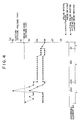
- Fig. 1 illustrates a driving system for a recording head according to a first embodiment of the present invention.
- the recording head 1 comprises a plurality of recording elements 2 (2-1, 2-2, ..., 2-n, 2-n+1, ..., 2-2n), which are divided into blocks each having n recording elements.
- the recording elements belonging to the blocks 1 and 2 are respectively driven by output pulses supplied from driving ICs 4-1 and 4-2 for ejection wave form output (referred to as ejection wave form output ICs 4-1 and 4-2 hereinafter).
- the recording head according to this embodiment is characterised in that characteristic correction for the recording elements can be realized at low cost only by providing on the recording device body 5 itself a memory circuit 6 for recording characteristics correction (hereinafter referred to as recording characteristics correction memory circuit 6) which stores recording characteristic correction data of IC4-1 and IC4-2.
- recording characteristics correction memory circuit 6 for recording characteristics correction
- Numeral 7 denotes a pulse wave form correction signal output circuit for reading correction data supplied out of the recording circuit 6 so as to output a signal for correcting pulse wave form supplied from the driving ICs 4-1 and 4-2.
- either a combination of a picture image signal S1 and a selection signal SEL1 or a combination of a picture image signal S1 and a selecting signal SEL2 is alternately supplied to the driving ICs 4-1 and 4-2, and a wave form correction signal is supplied from the pulse wave form correction signal output circuit to the driving ICs 4-1 and 4-2.
- output wave forms respectively predetermined are corrected in accordance with the above correction signals, and signals having corrected pulse wave forms are supplied to the respective recording elements 2, so that, for example the diameters of dots of a recorded picture image can be corrected as a whole.
- a recording density of recording head 1 is set to a high resolution, for instance, of 400 dpi and that the recording elements 1, 2, 3, ..., 16, ... on the recording head are driven separately at respective blocks, i.e., blocks B1, B2, B3, ... as shown in Figs. 2 and 3.
- diameters of recording dots is diverse according to respective recording elements as denoted by white circles in Fig. 2.
- the thickness unevenness appears because diversity in diameter of recording dots, which is caused by diversity in recording characteristic of recording elements, appears to the eyes of viewers thickness distribution represented by an averaged continuously shaped line, as shown by solid line in Fig. 3.
- diversity in recording dot depending on respective recording elements are recognized as an areal thickness uneveness having a width wider than a pitch between the recording elements on the recording image, such as the areas having a thick recording thickness or an area having a light recording thickness.
- correction for respective recording elements of the recording head is performed separately at each block having a plurality of recording elements. More specifically, with respect to the recording elements in the area having thick recording thickness, that is, the area having relatively high average dot diameter, for example, the recording elements belonging to recording element blocks B1, B2, B3 and B4, correcting operation is performed so as to lower the recorded thickness of all the plurality recording elements at a time, while with respect to the recording elements belonging to the area having relatively light thickness, as in the recording element block B2, correcting operation is performed so as to elevate recorded thickness of all the plurality of recording elements at a time.
- the thickness unevenness on the actual recorded picture images having a width wider than the pitch of the recording elements, conspicuous to the eyes of viewers, can be improved by correcting recording characteristics at respective recording blocks, not by employing a constitution in which recording characteristic is corrected respectively at each recording element.
- a constitution is also effective in which by grouping the correction data corresponding to several ICs in accordance with the first embodiment into one block so as to divide all the correction data into three blocks, i.e. blocks in both end parts and a middle part.
- the number of correction data can be decreased, and therefore the memory capacity of the memory circuit 6 is decreased.
- constitution is not necessarily limited to one in which one IC is grouped as one block.
- the third embodiment is oriented to prolongation of recording head's life.
- the recording head such as in a thermal head, ink jet head utilizing heat energy, where the diversity on the recording head is caused by the diversity in the resistor values at respective elements, where driving application energy is determined in accordance with recording elements having lower resistance, energy is applied to the recording elements having higher resistance above a required level, and therefore the life of the recording head is likely to be shortened.
- Fig. 4 is a view showing an example of diversity in ejection critical voltage (Vth) on the above-mentioned multi-head.
- the ejection critical voltage in this context means the lowest voltage required to eject ink out of each orifice of the multi-head.
- rectangular pulse wave form having pulse width 7 is applied to all the ranges a , b and c , marks representing ejection critical voltages of respective recording elements before correction.
- the head driving voltage (Vd) in the figure is set corresponding to the recording element having the lowest ejection critical voltage in one recording head. In this case, the head driving voltage is set to 30.8 [V] obtained by multiplying by 1.1 the lowest ejection critical voltage 28 [V] of the recording element No. 1.
- the voltage value is set so that the voltage is the most suitable for the recording element having the lowest ejection critical voltage when operated at this voltage, in other words, the value enabling the most suitable operation.
- the recording elements belonging to respective areas a , b , and c are respectively driven by pulses having pulse widths 7 ⁇ s, 7.5 ⁇ s and 8 ⁇ s.
- the pulse width By setting the pulse width to be long, generated thermal energy is increased, and therefore the ejection critical voltage [Vth] is substantially lowered.
- the diversion in the ejection critical voltage [Vth] of respective recording elements is restrained than in the case of no correction represented by mark ⁇ .
- the recording head having such constitution as this embodiment diversity among the recording elements is so large that the recording head cannot be put into practical use.
- the division into blocks is rough, pulse widths are controlled at respective blocks, and therefore stable recording can be achieved and the production rate of usable recording head is enhanced.
- driving can be effected at an even and a nearly optimal voltage and pulse width, and therefore recording head's life can be prolonged and diversity in diameter of ejection dots caused by diversity application energy can be prevented.
- a voltage value or a current value may be controlled instead of the pulse width.
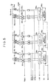
- Fig. 5 shows a constitution of the recording head driving circuit according to a fourth embodiment.
- R l to R mn each denotes an electricity-heat converter having one end connected a common electrode V for applying voltage V H to the converters, and the other end connected to earth terminal P GND . Therefore, the shift registers 39 l to 39 m are respectively an n-bit shift registers, each output of which corresponds to the corresponds to each of n electricity-heat converters of each block.
- Symbol SI denotes a terminal for inputting recording data SI which is serially inputted into the shift register at the first stage in accordance with recording data transmitting clocks SCLK, and serially shifted, and thus n x m recording data SI is stored in the registers 39 l to 39 m .
- the recording data transmitting clock SCLK for transmitting data to the shift registers 39 l to 39 m inputs as many clock pulses as electricity-heat converters on one line.
- BEI represents a terminal for inputting a basic signal BEI, the pulse width thereof being a conducting time correspondent to the electricity required for driving in a divided manner and corresponding to energy required for ejecting ink to electricity heat converter elements R l to R mn . It should be noted, in this embodiment, the pulse width of the signal BEI can be variable corresponding to the block to be driven.
- the characteristic of the recording element can be corrected on the block basis. It should be noted that, although the pulse width of the signal BEI is set to be variable in the above-mentioned embodiment, the pulse width of the strobe signal STB may be set to be variable.
- the present invention brings about excellent effects particularly in a recording head, recording device of ink jet system utilizing thermal energy among the ink jet recording system.
- the on-demand type is effective because, by applying at least one driving signal which gives rapid temperature elevation exceeding nucleus boiling corresponding to the recording information on an electricity-heat convertors arranged corresponding to the sheets or liquid channels holding liquid (ink), heat energy is generated at the electricity-heat convertors to effect film boiling at the heat acting surface of the recording head, and consequently the bubbles within the liquid (ink) can be formed corresponding one by one to the driving signals.
- the constitution of the recording head in addition to the combination constitutions of discharging orifice, liquid channel, electricity-heat converter (linera liquid channel or right angle liquid channel) as disclosed in the above-mentioned respective specifications, the constitution by use of U.S. Patent 4,558,333, 4,459,600 disclosing the constitution having the heat acting portion arranged in the flexed region is also included in the present invention.
- the present invention can be also effectively made the constitution as disclosed in Japanese Patent Laid-Open Application No. 59-123670 which discloses the constitution using a slit common to a plurality of electricity-heat converters as the discharging portion of the electricity-heat converter or Japanese Patent Laid-Open Application No. 59-138461 which discloses the constitution having the opening for absorbing pressure wave of heat energy correspondent to the discharging portion.
- the recording head of the full line type having a length corresponding to the maximum width of recording medium which can be recorded by the recording device
- either the constitution which satisfies its length by combination of a plurality of recording heads as disclosed in the above-mentioned specifications or the constitution as one recording head integrally formed may be used, and the present invention can exhibit the effects as described above further effectively.
- the present invention is effective for a recording head of the freely exchangeable chip type which enables electrical connection to the main device or supply of ink from the main device by being mounted on the main device, or for the case by use of a recording head of the cartridge type provided integrally on the recording head itself.
- a restoration means for the recording head, a preliminary means, etc. provided as the constitution of the recording device of the present invention is preferrable, because the effect of the present invention can be further stabilized.
- Specific examples of these may include, for the recording head, capping means, cleaning means, pressurization or aspiration means, electricity-heat convertors or another heating element or preliminary heating means according to a combination of these and it is also effective for performing stable recording to perform preliminary mode which performs discharging separate from recording.
- the present invention is extremely effective for not only the recording mode only of a primary color such as black etc., but also a device equipped with at least one of plural different colors or full color by color mixing, whether the recording head may be either integrally constituted or combined in plural number.
- each of at least two blocks each having recording heads simultaneously operable wherein the characteristics of the plurality of the recording elements belonging to one block are corrected simultaneously by use of means for correcting the characteristics of the recording elements in accordance with electrical energy, whereby the diversity in recording characteristics of the respective recording elements can be corrected separately at each block from a macroscopic point of view, the life of recording head can be prolonged and a high quality picture image can be obtained at low cost.
- recording characteristic can be corrected at each block, and therefore high quality picture image free from thickness unevenness can be obtained at a low cost.
Abstract
Description
- The present invention relates to a recording head for use in a printer, a facsimile device, a copying machine, etc., and to a recording device utilizing the recording head.
- Currently, as a recording head for use in a printer, a facsimile device, copying machine, etc., a so-called multi-recording head is used wherein a plurality of recording elements are arranged on a single recording head so as to achieve shortening of recording time and high speed recording.
- However, because of manufacturing restriction, where the respective recording elements on the single multi-recording head are driven under the same recording condition, it is very difficult to obtain evenness in recording characteristics of respective recording elements, and consequently the thickness in a recorded picture image becomes uneven. To the contrary, where obtaining evenness in recording characteristic is pursued, a production rate of usable recording heads becomes low.
- As one of measures to obviate the above defects, a constitution can be proposed wherein correcting means for correcting energy amount to be applied to the respective recording elements in accordance with the respective recording characteristics thereof is provided on the recording head having recording elements of uneven recording characteristics.
- However, where the number of correcting means to be provided on the recording head increases or the recording density rises, the number of the recording means to be provided increases, and consequently the device becomes large and the production cost becomes high.
- Therefore, an object of the present invention is to provide a recording head and a recording device utilizing the recording head, wherein the recording characteristics of the respective recording elements are corrected by simple correcting means so as to prevent thickness unevenness.
- Another object of the present invention to provide a recording head comprising simple recording means, whereby the production rate of usable recording head is enhanced.
- The recording head according to the present invention having a plurality of recording elements, wherein the recording elements are arranged and selectively supplied with driving signals and driven by electrical energy thereof, for performing a recording operation, comprising: dividing means for dividing the plurality of arranged recording elements into at least two blocks each wherein simultaneous driving can be performed; and correcting means for correcting the characteristics of the recording elements with respect to the electrical energy at respective blocks divided by the dividing means.
- The recording device according to the present invention is a recording device utilizing a recording head having a plurality of arranged recording elements, wherein the plurality of recording elements are selectively supplied with driving signals and driven by the electrical energy thereof, comprises: supply means for selectively supplying an electrical signal by a predetermined unit to the plurality of the recording elements arranged on the recording head; and correcting means for correcting by the predetermined unit the electrical signal supplied by the supply means so as to correct the characteristics of the recording elements with respect to the electrical energy.
-
- Fig. 1 is a block diagram showing a constitution of a driving circuit according to an embodiment of the present invention;
- Figs. 2 and 3 are views for illustration with graphs showing an example of correcting operations at each block according to the present invention;
- Fig. 4 is a view for illustration with a graph showing an example of a correction according to another embodiment wherein the present invention is applied to an ink jet recording head utilizing thermal energy; and
- Fig. 5 is a block diagram showing a constitution according to still another embodiment of the present invention.
- Preferred embodiments of the present invention will be described referring to the attached drawings hereinafter.
- Fig. 1 illustrates a driving system for a recording head according to a first embodiment of the present invention. In the figure, the
recording head 1 comprises a plurality of recording elements 2 (2-1, 2-2, ..., 2-n, 2-n+1, ..., 2-2n), which are divided into blocks each having n recording elements. The recording elements belonging to theblocks recording device body 5 itself amemory circuit 6 for recording characteristics correction (hereinafter referred to as recording characteristics correction memory circuit 6) which stores recording characteristic correction data of IC4-1 and IC4-2. - Numeral 7 denotes a pulse wave form correction signal output circuit for reading correction data supplied out of the
recording circuit 6 so as to output a signal for correcting pulse wave form supplied from the driving ICs 4-1 and 4-2. - In the recording head driving system having the above constitution, either a combination of a picture image signal S1 and a selection signal SEL1 or a combination of a picture image signal S1 and a selecting signal SEL2 is alternately supplied to the driving ICs 4-1 and 4-2, and a wave form correction signal is supplied from the pulse wave form correction signal output circuit to the driving ICs 4-1 and 4-2. In the drive ICs 4-1 and 4-2, output wave forms respectively predetermined are corrected in accordance with the above correction signals, and signals having corrected pulse wave forms are supplied to the
respective recording elements 2, so that, for example the diameters of dots of a recorded picture image can be corrected as a whole. - Suppose that a recording density of
recording head 1 is set to a high resolution, for instance, of 400 dpi and that therecording elements - Where unevenness in thickness is visually recognized in an actual recorded picture image, the thickness unevenness appears because diversity in diameter of recording dots, which is caused by diversity in recording characteristic of recording elements, appears to the eyes of viewers thickness distribution represented by an averaged continuously shaped line, as shown by solid line in Fig. 3. In other words, diversity in recording dot depending on respective recording elements are recognized as an areal thickness uneveness having a width wider than a pitch between the recording elements on the recording image, such as the areas having a thick recording thickness or an area having a light recording thickness.
- To obviate the foregoing defects, according to this embodiment, correction for respective recording elements of the recording head is performed separately at each block having a plurality of recording elements. More specifically, with respect to the recording elements in the area having thick recording thickness, that is, the area having relatively high average dot diameter, for example, the recording elements belonging to recording element blocks B1, B2, B3 and B4, correcting operation is performed so as to lower the recorded thickness of all the plurality recording elements at a time, while with respect to the recording elements belonging to the area having relatively light thickness, as in the recording element block B2, correcting operation is performed so as to elevate recorded thickness of all the plurality of recording elements at a time.
- Thus, in the first embodiment, as denoted by black circles in Fig. 2 and broken line in Fig. 3, the thickness unevenness on the actual recorded picture images having a width wider than the pitch of the recording elements, conspicuous to the eyes of viewers, can be improved by correcting recording characteristics at respective recording blocks, not by employing a constitution in which recording characteristic is corrected respectively at each recording element.
- In the first embodiment, description was as to the case where correction of recording characteristic is performed at each block corresponding to one IC block.
- However, in some recording head, there is a large diversity between the middle part and the both end parts. Particularly, in the so called full-multi-ink-jet head having a long recording head length, the diversity between the middle part and the both end parts is remarkably large because of problems on the ink supply path, etc. Further, in some of thermal heads, there is diversity in thickness caused by the difference in temperature between the both end part and the middle part.
- To obviate these problems, as a second embodiment (not shown), a constitution is also effective in which by grouping the correction data corresponding to several ICs in accordance with the first embodiment into one block so as to divide all the correction data into three blocks, i.e. blocks in both end parts and a middle part. With this constitution, the number of correction data can be decreased, and therefore the memory capacity of the
memory circuit 6 is decreased. Thus, in the present invention, constitution is not necessarily limited to one in which one IC is grouped as one block. - Next, a third embodiment will be described hereinafter. The third embodiment is oriented to prolongation of recording head's life. In the recording head, such as in a thermal head, ink jet head utilizing heat energy, where the diversity on the recording head is caused by the diversity in the resistor values at respective elements, where driving application energy is determined in accordance with recording elements having lower resistance, energy is applied to the recording elements having higher resistance above a required level, and therefore the life of the recording head is likely to be shortened.
- In the third embodiment, an ink jet multi-head utilizing heat energy will be described with a concrete example.
- Fig. 4 is a view showing an example of diversity in ejection critical voltage (Vth) on the above-mentioned multi-head. The ejection critical voltage in this context means the lowest voltage required to eject ink out of each orifice of the multi-head. It should be noted that, in this embodiment, rectangular pulse wave form having
pulse width 7 is applied to all the ranges a, b and c, marks representing ejection critical voltages of respective recording elements before correction. The head driving voltage (Vd) in the figure is set corresponding to the recording element having the lowest ejection critical voltage in one recording head. In this case, the head driving voltage is set to 30.8 [V] obtained by multiplying by 1.1 the lowest ejection critical voltage 28 [V] of the recording element No. 1. The voltage value is set so that the voltage is the most suitable for the recording element having the lowest ejection critical voltage when operated at this voltage, in other words, the value enabling the most suitable operation. - However, in the recording element (No. 230) wherein, as shown in the figure, the head driving voltage (Vd) does not reach ejection critical voltage represented by mark, ink is not ejected. To the contrary, if the optimal driving voltage (32 [V] x 1.1 = 35.2 [V]) of the recording element (No. 230) is applied, the other recording elements, for instance No. 1, is applied with an excessive voltage, so that the life of the recording head is remarkably shortened.
- To obviate the foregoing problem, by dividing the range into three areas a, b and c, as shown in the figure the recording elements belonging to respective areas a, b, and c are respectively driven by pulses having
pulse widths 7 µs, 7.5 µs and 8 µs. By setting the pulse width to be long, generated thermal energy is increased, and therefore the ejection critical voltage [Vth] is substantially lowered. With this constitution, as is represented by x, the diversion in the ejection critical voltage [Vth] of respective recording elements is restrained than in the case of no correction represented by mark Δ. - With this constitution according this embodiment, although there is diversity among the recording elements, non-ejection of ink and shortening of head's life can be prevented.
- Generally speaking, in the recording head having such constitution as this embodiment, diversity among the recording elements is so large that the recording head cannot be put into practical use. In contrast, in the present embodiment, although the division into blocks is rough, pulse widths are controlled at respective blocks, and therefore stable recording can be achieved and the production rate of usable recording head is enhanced. In addition, as to a head having the smallest diversion, driving can be effected at an even and a nearly optimal voltage and pulse width, and therefore recording head's life can be prolonged and diversity in diameter of ejection dots caused by diversity application energy can be prevented. Incidentally, a voltage value or a current value may be controlled instead of the pulse width.
- Fig. 5 shows a constitution of the recording head driving circuit according to a fourth embodiment. In this figure is shown a driving circuit for driving electricity-heat converters belonging to m (= 37) blocks, one block including n (= 128) electricity-heat converters (resistors). Therefore, n electricity-heat convertor corresponds to one unit of driving IC comprising a latch circuits 38l to 38m, shift register 39l to 39m and AND gates 37l to 37m. Further, in the figure, Rl to Rmn each denotes an electricity-heat converter having one end connected a common electrode V for applying voltage VH to the converters, and the other end connected to earth terminal PGND. Therefore, the shift registers 39l to 39m are respectively an n-bit shift registers, each output of which corresponds to the corresponds to each of n electricity-heat converters of each block.
- Symbol SI denotes a terminal for inputting recording data SI which is serially inputted into the shift register at the first stage in accordance with recording data transmitting clocks SCLK, and serially shifted, and thus n x m recording data SI is stored in the registers 39l to 39m.
- After transmitting recording data of one line, these data are latched by the n-bit latch circuits 38l to 38m in accordance with the signals LAT input. Thus, correspondence between each of electricity-heat converter element Rl to Rmn and recording data is made. It should be noted that the recording data transmitting clock SCLK for transmitting data to the shift registers 39l to 39m inputs as many clock pulses as electricity-heat converters on one line.
- BEI represents a terminal for inputting a basic signal BEI, the pulse width thereof being a conducting time correspondent to the electricity required for driving in a divided manner and corresponding to energy required for ejecting ink to electricity heat converter elements Rl to Rmn. It should be noted, in this embodiment, the pulse width of the signal BEI can be variable corresponding to the block to be driven.
- Symbols STBl to STBm each designate strobe signals, while each of the driving blocks to be supplied with these signals comprises n (= 128) elements.
- In the recording head having such constitution, 4736-bit recording image signals corresponding to one recording line is input, and the recording picture image signal is latched by the latch signal LAT to the respective latch circuits 38l to 38m, and strobe signals STBl to STBm (in this case m = 37) are serially turned on, thereby completing drive of each driving block.
- As described above, in the present embodiment, recording elements can be driven at different pulse width at each driving block (m = 1 to 37). That is to say that 128 nozzles are controlled as one block by setting the pulse width of the signal BEI to be variable in accordance with data of the pulse width corresponding to each block stored in the memory circuit for storing a recording characteristic correction.
- In the above-mentioned embodiment, the characteristic of the recording element can be corrected on the block basis. It should be noted that, although the pulse width of the signal BEI is set to be variable in the above-mentioned embodiment, the pulse width of the strobe signal STB may be set to be variable.
- The present invention brings about excellent effects particularly in a recording head, recording device of ink jet system utilizing thermal energy among the ink jet recording system.
- As to its representative constitution and principle, for example, one practiced by use of the basic principle disclosed in, for example, U.S. Patents 4,723,129 and 4,740,796 is preferred. This system is applicable to either of the so called on-demand type and the continuous type. Particularly, the case of the on-demand type is effective because, by applying at least one driving signal which gives rapid temperature elevation exceeding nucleus boiling corresponding to the recording information on an electricity-heat convertors arranged corresponding to the sheets or liquid channels holding liquid (ink), heat energy is generated at the electricity-heat convertors to effect film boiling at the heat acting surface of the recording head, and consequently the bubbles within the liquid (ink) can be formed corresponding one by one to the driving signals. By discharging the liquid (ink) through an opening for discharging by growth and shrinkage of the bubble, at least one droplet is formed. By making the driving signals into pulse shapes, growth and shrinkage of the bubble can be effected instantly and adequately to accomplish more preferably discharging of the liquid (ink) particularly excellent in response characteristic. As the driving signals of such pulse shape, those as disclosed in U.S. Patents 4,463,359 and 4,345,262 are suitable. Further excellent recording can be performed by employment of the conditions described in U.S. Patent 4,313,124 of the invention concerning the temperature elevation rate of the above-mentioned heat acting surface.
- As the constitution of the recording head, in addition to the combination constitutions of discharging orifice, liquid channel, electricity-heat converter (linera liquid channel or right angle liquid channel) as disclosed in the above-mentioned respective specifications, the constitution by use of U.S. Patent 4,558,333, 4,459,600 disclosing the constitution having the heat acting portion arranged in the flexed region is also included in the present invention. In addition, the present invention can be also effectively made the constitution as disclosed in Japanese Patent Laid-Open Application No. 59-123670 which discloses the constitution using a slit common to a plurality of electricity-heat converters as the discharging portion of the electricity-heat converter or Japanese Patent Laid-Open Application No. 59-138461 which discloses the constitution having the opening for absorbing pressure wave of heat energy correspondent to the discharging portion.
- Further, as the recording head of the full line type having a length corresponding to the maximum width of recording medium which can be recorded by the recording device, either the constitution which satisfies its length by combination of a plurality of recording heads as disclosed in the above-mentioned specifications or the constitution as one recording head integrally formed may be used, and the present invention can exhibit the effects as described above further effectively.
- In addition, the present invention is effective for a recording head of the freely exchangeable chip type which enables electrical connection to the main device or supply of ink from the main device by being mounted on the main device, or for the case by use of a recording head of the cartridge type provided integrally on the recording head itself.
- Also, addition of a restoration means for the recording head, a preliminary means, etc. provided as the constitution of the recording device of the present invention is preferrable, because the effect of the present invention can be further stabilized. Specific examples of these may include, for the recording head, capping means, cleaning means, pressurization or aspiration means, electricity-heat convertors or another heating element or preliminary heating means according to a combination of these and it is also effective for performing stable recording to perform preliminary mode which performs discharging separate from recording.
- Further, as the recording mode of the recording device, the present invention is extremely effective for not only the recording mode only of a primary color such as black etc., but also a device equipped with at least one of plural different colors or full color by color mixing, whether the recording head may be either integrally constituted or combined in plural number.
- According to this invention, with respect to each of at least two blocks each having recording heads simultaneously operable, wherein the characteristics of the plurality of the recording elements belonging to one block are corrected simultaneously by use of means for correcting the characteristics of the recording elements in accordance with electrical energy, whereby the diversity in recording characteristics of the respective recording elements can be corrected separately at each block from a macroscopic point of view, the life of recording head can be prolonged and a high quality picture image can be obtained at low cost.
- Further, according to the present invention, recording characteristic can be corrected at each block, and therefore high quality picture image free from thickness unevenness can be obtained at a low cost.
Claims (19)
- A recording head having a plurality of arranged recording elements, wherein the recording elements are selectively supplied with driving signals and driven by electrical energy thereof, for performing recording operation, comprising:
dividing means for dividing the arranged plurality of recording elements into a plurality of blocks each having the recording elements operable simultaneously; and
correcting means for simultaneously correcting characteristics of the recording elements with respect to the electrical energy separately at each block divided by the dividing means. - A recording head according to claim 1, wherein the dividing means divides the plurality of arranged recording elements into three blocks, i.e., blocks of both end parts and middle part.
- A recording head according to claim 1, wherein the recording element has an ejection orifice for ejecting ink.
- A recording head according to claim 3, wherein the recording element has a thermal energy generating means provided at the ejecting orifice so as to form spersing drops by changing ink state by heat and ejecting ink out of the orifice in accordance with the change of ink state.
- A recording head according to claim 3, wherein the correcting means corrects a pulse width of a driving signal.
- A recording head according to claim 1, wherein the correcting means corrects a current value or a voltage value of the driving signal.
- A recording head according to claim 1, wherein the recording means are provided according to a width of recording media.
- A recording device for recording by use of a recording head having a plurality of arranged recording elements, wherein the recording elements are supplied with a plurality of driving signals and driven by electrical energy thereof, comprising:
supply means for selectively supplying, by a predetermined unit, driving signals to the plurality of recording elements arranged on the recording head; and
correcting means for correcting the driving signal supplied by the supply means by the predetermined unit so as to correct characteristics of the recording elements in accordance with the electrical energy. - A recording device according to claim 8, wherein the recording element has an ejection orifice for ejecting ink.
- A recording device according to claim 9, wherein the recording element has a thermal energy generating means provided at the ejecting orifice so as to form spersing drops by changing ink state by heat and ejecting ink out of the orifice in accordance with the change of ink state.
- A recording device according to claim 8, wherein the correcting means corrects a pulse width of a driving signal.
- A recording device according to claim 8, wherein the correcting means corrects a current value or a voltage value of the driving signal.
- A recording device according to claim 8, wherein the recording means are provided according to a width of recording media.
- A method of driving a recording head having a plurality of recording elements, wherein the recording elements are supplied with a plurality of driving signals and driven by electrical energy thereof, so as perform a recording operation, comprising steps of:
dividing the plurality of arranged recording elements into plurality of blocks each in which the recording elements can be operated simultaneously; and
simultaneously correcting characteristics of the recording elements separately at each of the blocks by use of means for correcting a characteristic of recording signal with respect to the electrical energy. - A method of driving a recording head according to claim 14, wherein the recording element has an ejection orifice for ejecting ink.
- A method of driving a recording head according to claim 15, wherein the recording element has a thermal energy generating means provided at the ejecting orifice so as to form spersing drops by changing ink state by heat and ejecting ink out of the orifice in accordance with the change of ink state.
- A method of driving a recording head according to claim 14, wherein the correcting means corrects a pulse width of a driving signal.
- A method of driving a recording head according to claim 14, wherein the correcting means corrects a current value or a voltage value of the driving signal.
- A recording head according to claim 14, wherein the recording means are provided according to a width of recording media.
Applications Claiming Priority (2)
| Application Number | Priority Date | Filing Date | Title |
|---|---|---|---|
| JP2219290A JP2863241B2 (en) | 1990-02-02 | 1990-02-02 | Printhead and printhead driving method |
| JP22192/90 | 1990-02-02 |
Publications (3)
| Publication Number | Publication Date |
|---|---|
| EP0440492A2 true EP0440492A2 (en) | 1991-08-07 |
| EP0440492A3 EP0440492A3 (en) | 1991-12-27 |
| EP0440492B1 EP0440492B1 (en) | 1996-05-08 |
Family
ID=12075938
Family Applications (1)
| Application Number | Title | Priority Date | Filing Date |
|---|---|---|---|
| EP91300805A Expired - Lifetime EP0440492B1 (en) | 1990-02-02 | 1991-01-31 | Recording head and a recording device utilizing the recording head |
Country Status (4)
| Country | Link |
|---|---|
| US (1) | US5157411A (en) |
| EP (1) | EP0440492B1 (en) |
| JP (1) | JP2863241B2 (en) |
| DE (1) | DE69119251T2 (en) |
Cited By (7)
| Publication number | Priority date | Publication date | Assignee | Title |
|---|---|---|---|---|
| EP0551013A2 (en) * | 1992-01-09 | 1993-07-14 | Canon Kabushiki Kaisha | Recording head system for ink jet recording apparatus and method for driving the same |
| EP0709192A3 (en) * | 1994-10-28 | 1996-07-31 | Canon Kk | Method and apparatus for correcting printhead, printhead corrected by this apparatus, and printing apparatus using this printhead |
| EP0709196A3 (en) * | 1994-10-27 | 1996-09-04 | Canon Kk | Print head, and print method and apparatus using the same |
| EP0709213A3 (en) * | 1994-10-28 | 1996-09-04 | Canon Kk | Method and apparatus for correcting printhead and printer using this printhead |
| EP0761440A2 (en) * | 1995-09-08 | 1997-03-12 | Canon Kabushiki Kaisha | Ink-jet printing method and apparatus, and method and apparatus for manufacturing color filter |
| US5997123A (en) * | 1990-05-11 | 1999-12-07 | Canon Kabushiki Kaisha | Image recording apparatus having density correction of plural recording elements |
| EP1238708A1 (en) * | 2000-10-17 | 2002-09-11 | Seiko Epson Corporation | Ink jet recorder and method of manufacturing functional liquid applied substrate |
Families Citing this family (19)
| Publication number | Priority date | Publication date | Assignee | Title |
|---|---|---|---|---|
| US5610639A (en) * | 1989-02-14 | 1997-03-11 | Canon Kabushiki Kaisha | Image forming apparatus with a correction recording condition feature and related method |
| GB2242046B (en) * | 1990-02-02 | 1994-06-01 | Canon Kk | Recording method and apparatus |
| JP3313819B2 (en) * | 1992-07-06 | 2002-08-12 | キヤノン株式会社 | Recording device and method |
| JP3155400B2 (en) | 1993-06-30 | 2001-04-09 | キヤノン株式会社 | Ink jet recording device |
| JP3376036B2 (en) * | 1993-09-24 | 2003-02-10 | キヤノン株式会社 | Ink jet recording apparatus and recording method |
| US6116714A (en) * | 1994-03-04 | 2000-09-12 | Canon Kabushiki Kaisha | Printing head, printing method and apparatus using same, and apparatus and method for correcting said printing head |
| US5497174A (en) * | 1994-03-11 | 1996-03-05 | Xerox Corporation | Voltage drop correction for ink jet printer |
| US5867183A (en) * | 1996-01-11 | 1999-02-02 | Lexmark International, Inc. | Apparatus for driving multiple ink jet printheads with a single set of drive outputs |
| US5901425A (en) | 1996-08-27 | 1999-05-11 | Topaz Technologies Inc. | Inkjet print head apparatus |
| US6312078B1 (en) * | 1997-03-26 | 2001-11-06 | Eastman Kodak Company | Imaging apparatus and method of providing images of uniform print density |
| US6176569B1 (en) | 1999-08-05 | 2001-01-23 | Lexmark International, Inc. | Transitional ink jet heater addressing |
| US7390070B2 (en) * | 2004-06-04 | 2008-06-24 | Brother Kogyo Kabushiki Kaisha | Ink-jet printer |
| JP2006137131A (en) * | 2004-11-15 | 2006-06-01 | Konica Minolta Holdings Inc | Liquid ejecting apparatus and liquid ejection method |
| JP4650005B2 (en) * | 2005-01-27 | 2011-03-16 | 富士ゼロックス株式会社 | Droplet discharge device |
| JP4757011B2 (en) * | 2005-12-16 | 2011-08-24 | キヤノン株式会社 | Ink jet recording head and manufacturing method |
| JP4905380B2 (en) * | 2008-02-08 | 2012-03-28 | セイコーエプソン株式会社 | Drive signal setting method |
| JP2009189954A (en) * | 2008-02-14 | 2009-08-27 | Seiko Epson Corp | Method of setting driving signal |
| JP5293408B2 (en) * | 2009-05-29 | 2013-09-18 | 株式会社リコー | Image forming apparatus |
| JP6164476B2 (en) * | 2013-07-25 | 2017-07-19 | ブラザー工業株式会社 | Printing device |
Citations (3)
| Publication number | Priority date | Publication date | Assignee | Title |
|---|---|---|---|---|
| EP0279637A2 (en) * | 1987-02-18 | 1988-08-24 | Matsushita Electric Industrial Co., Ltd. | Thermal printer |
| EP0318328A2 (en) * | 1987-11-27 | 1989-05-31 | Canon Kabushiki Kaisha | Ink jet recording device |
| US4875056A (en) * | 1986-01-17 | 1989-10-17 | Canon Kabushiki Kaisha | Thermal recording apparatus with variably controlled energization of the heating elements thereof |
Family Cites Families (13)
| Publication number | Priority date | Publication date | Assignee | Title |
|---|---|---|---|---|
| CA1127227A (en) * | 1977-10-03 | 1982-07-06 | Ichiro Endo | Liquid jet recording process and apparatus therefor |
| US4330787A (en) * | 1978-10-31 | 1982-05-18 | Canon Kabushiki Kaisha | Liquid jet recording device |
| US4345262A (en) * | 1979-02-19 | 1982-08-17 | Canon Kabushiki Kaisha | Ink jet recording method |
| US4520373A (en) * | 1979-04-02 | 1985-05-28 | Canon Kabushiki Kaisha | Droplet generating method and apparatus therefor |
| US4463359A (en) * | 1979-04-02 | 1984-07-31 | Canon Kabushiki Kaisha | Droplet generating method and apparatus thereof |
| US4313124A (en) * | 1979-05-18 | 1982-01-26 | Canon Kabushiki Kaisha | Liquid jet recording process and liquid jet recording head |
| JPH0764085B2 (en) * | 1981-06-08 | 1995-07-12 | 富士ゼロックス株式会社 | Thermal recording device |
| US4558333A (en) * | 1981-07-09 | 1985-12-10 | Canon Kabushiki Kaisha | Liquid jet recording head |
| JPS5856874A (en) * | 1981-09-30 | 1983-04-04 | Sharp Corp | Heat sensitive recording device |
| JPS59123670A (en) * | 1982-12-28 | 1984-07-17 | Canon Inc | Ink jet head |
| JPS59138461A (en) * | 1983-01-28 | 1984-08-08 | Canon Inc | Liquid jet recording apparatus |
| JPS6026854U (en) * | 1983-08-01 | 1985-02-23 | 沖電気工業株式会社 | optical print head |
| JPS63227358A (en) * | 1987-03-18 | 1988-09-21 | Oki Electric Ind Co Ltd | Method for driving light emitting element array |
-
1990
- 1990-02-02 JP JP2219290A patent/JP2863241B2/en not_active Expired - Fee Related
-
1991
- 1991-01-31 EP EP91300805A patent/EP0440492B1/en not_active Expired - Lifetime
- 1991-01-31 DE DE69119251T patent/DE69119251T2/en not_active Expired - Lifetime
- 1991-02-01 US US07/649,721 patent/US5157411A/en not_active Expired - Lifetime
Patent Citations (3)
| Publication number | Priority date | Publication date | Assignee | Title |
|---|---|---|---|---|
| US4875056A (en) * | 1986-01-17 | 1989-10-17 | Canon Kabushiki Kaisha | Thermal recording apparatus with variably controlled energization of the heating elements thereof |
| EP0279637A2 (en) * | 1987-02-18 | 1988-08-24 | Matsushita Electric Industrial Co., Ltd. | Thermal printer |
| EP0318328A2 (en) * | 1987-11-27 | 1989-05-31 | Canon Kabushiki Kaisha | Ink jet recording device |
Cited By (16)
| Publication number | Priority date | Publication date | Assignee | Title |
|---|---|---|---|---|
| US5997123A (en) * | 1990-05-11 | 1999-12-07 | Canon Kabushiki Kaisha | Image recording apparatus having density correction of plural recording elements |
| EP0842777A3 (en) * | 1992-01-09 | 1998-05-27 | Canon Kabushiki Kaisha | Recording head system for ink jet recording apparatus and method for driving the same |
| EP0551013A3 (en) * | 1992-01-09 | 1994-01-19 | Canon Kk | |
| US6102510A (en) * | 1992-01-09 | 2000-08-15 | Canon Kabushiki Kaisha | Recording head system for ink jet recording apparatus and method for driving the same |
| EP0551013A2 (en) * | 1992-01-09 | 1993-07-14 | Canon Kabushiki Kaisha | Recording head system for ink jet recording apparatus and method for driving the same |
| EP0842777A2 (en) * | 1992-01-09 | 1998-05-20 | Canon Kabushiki Kaisha | Recording head system for ink jet recording apparatus and method for driving the same |
| EP0709196A3 (en) * | 1994-10-27 | 1996-09-04 | Canon Kk | Print head, and print method and apparatus using the same |
| US5867200A (en) * | 1994-10-27 | 1999-02-02 | Canon Kabushiki Kaisha | Print head, and print pre-heat method and apparatus using the same |
| EP0709213A3 (en) * | 1994-10-28 | 1996-09-04 | Canon Kk | Method and apparatus for correcting printhead and printer using this printhead |
| US6036297A (en) * | 1994-10-28 | 2000-03-14 | Canon Kabushiki Kaisha | Method and apparatus for correcting printhead, printhead correction by this apparatus, and printer using this printhead |
| US6042213A (en) * | 1994-10-28 | 2000-03-28 | Canon Kabushiki Kaisha | Method and apparatus for correcting printhead, printhead corrected by this apparatus, and printing apparatus using this printhead |
| EP0709192A3 (en) * | 1994-10-28 | 1996-07-31 | Canon Kk | Method and apparatus for correcting printhead, printhead corrected by this apparatus, and printing apparatus using this printhead |
| EP0761440A3 (en) * | 1995-09-08 | 1998-01-07 | Canon Kabushiki Kaisha | Ink-jet printing method and apparatus, and method and apparatus for manufacturing color filter |
| EP0761440A2 (en) * | 1995-09-08 | 1997-03-12 | Canon Kabushiki Kaisha | Ink-jet printing method and apparatus, and method and apparatus for manufacturing color filter |
| EP1238708A1 (en) * | 2000-10-17 | 2002-09-11 | Seiko Epson Corporation | Ink jet recorder and method of manufacturing functional liquid applied substrate |
| EP1238708A4 (en) * | 2000-10-17 | 2007-04-18 | Seiko Epson Corp | Ink jet recorder and method of manufacturing functional liquid applied substrate |
Also Published As
| Publication number | Publication date |
|---|---|
| US5157411A (en) | 1992-10-20 |
| JP2863241B2 (en) | 1999-03-03 |
| EP0440492B1 (en) | 1996-05-08 |
| EP0440492A3 (en) | 1991-12-27 |
| DE69119251T2 (en) | 1996-10-02 |
| JPH03227669A (en) | 1991-10-08 |
| DE69119251D1 (en) | 1996-06-13 |
Similar Documents
| Publication | Publication Date | Title |
|---|---|---|
| US5157411A (en) | Recording head and a recording device utilizing the recording head | |
| US7708365B2 (en) | Liquid-discharge recording head | |
| US5984449A (en) | Ink jet recording by superimposing inks of different densities | |
| KR100980124B1 (en) | Inkjet printhead | |
| US5717448A (en) | Ink jet printing apparatus and ink jet printing method | |
| EP0709196B1 (en) | Print head, and print method and apparatus using the same | |
| KR0137615B1 (en) | Ink-jet recording method and apparatus | |
| EP1193065B1 (en) | Ink jet printing apparatus and ink jet printing method | |
| US20020047873A1 (en) | Printing head, printing method and apparatus using same, and apparatus and method for correcting said printing head | |
| JPH0796607A (en) | Ink jet recording method and recording device | |
| EP0710562B1 (en) | Printer | |
| US5734391A (en) | Printing system | |
| JP4266588B2 (en) | Recording apparatus and recording control method | |
| JP3483444B2 (en) | Printing apparatus, printing system, and printing method | |
| JPH081962A (en) | Ink jet recording apparatus and method | |
| US6942309B2 (en) | Printing apparatus and method for maintaining temperature of a printhead | |
| JP2717798B2 (en) | Inkjet recording method | |
| US6198493B1 (en) | Recording apparatus | |
| US7618108B2 (en) | Inkjet recording apparatus | |
| JP2004122757A (en) | Inkjet recording head, method of driving the same, and substrate for inkjet recording head | |
| JP3140406B2 (en) | Ink jet recording head ejection drive method | |
| JPH05338208A (en) | Driving method for thermal head | |
| US8186796B2 (en) | Element substrate and printhead | |
| JP2817979B2 (en) | Ink jet recording apparatus, recording head, and method of driving the recording head | |
| JPH04241953A (en) | Recording head and recording apparatus using the same |
Legal Events
| Date | Code | Title | Description |
|---|---|---|---|
| PUAI | Public reference made under article 153(3) epc to a published international application that has entered the european phase |
Free format text: ORIGINAL CODE: 0009012 |
|
| AK | Designated contracting states |
Kind code of ref document: A2 Designated state(s): DE FR GB IT |
|
| PUAL | Search report despatched |
Free format text: ORIGINAL CODE: 0009013 |
|
| AK | Designated contracting states |
Kind code of ref document: A3 Designated state(s): DE FR GB IT |
|
| 17P | Request for examination filed |
Effective date: 19920513 |
|
| 17Q | First examination report despatched |
Effective date: 19930915 |
|
| GRAA | (expected) grant |
Free format text: ORIGINAL CODE: 0009210 |
|
| AK | Designated contracting states |
Kind code of ref document: B1 Designated state(s): DE FR GB IT |
|
| REF | Corresponds to: |
Ref document number: 69119251 Country of ref document: DE Date of ref document: 19960613 |
|
| ET | Fr: translation filed | ||
| ITF | It: translation for a ep patent filed |
Owner name: SOCIETA' ITALIANA BREVETTI S.P.A. |
|
| PLBE | No opposition filed within time limit |
Free format text: ORIGINAL CODE: 0009261 |
|
| STAA | Information on the status of an ep patent application or granted ep patent |
Free format text: STATUS: NO OPPOSITION FILED WITHIN TIME LIMIT |
|
| 26N | No opposition filed | ||
| REG | Reference to a national code |
Ref country code: GB Ref legal event code: IF02 |
|
| PGFP | Annual fee paid to national office [announced via postgrant information from national office to epo] |
Ref country code: IT Payment date: 20090119 Year of fee payment: 19 |
|
| PGFP | Annual fee paid to national office [announced via postgrant information from national office to epo] |
Ref country code: FR Payment date: 20090121 Year of fee payment: 19 |
|
| PGFP | Annual fee paid to national office [announced via postgrant information from national office to epo] |
Ref country code: GB Payment date: 20100126 Year of fee payment: 20 Ref country code: DE Payment date: 20100131 Year of fee payment: 20 |
|
| REG | Reference to a national code |
Ref country code: FR Ref legal event code: ST Effective date: 20100930 |
|
| PG25 | Lapsed in a contracting state [announced via postgrant information from national office to epo] |
Ref country code: FR Free format text: LAPSE BECAUSE OF NON-PAYMENT OF DUE FEES Effective date: 20100201 |
|
| REG | Reference to a national code |
Ref country code: GB Ref legal event code: PE20 Expiry date: 20110130 |
|
| PG25 | Lapsed in a contracting state [announced via postgrant information from national office to epo] |
Ref country code: IT Free format text: LAPSE BECAUSE OF NON-PAYMENT OF DUE FEES Effective date: 20100131 |
|
| PG25 | Lapsed in a contracting state [announced via postgrant information from national office to epo] |
Ref country code: GB Free format text: LAPSE BECAUSE OF EXPIRATION OF PROTECTION Effective date: 20110130 |
|
| PG25 | Lapsed in a contracting state [announced via postgrant information from national office to epo] |
Ref country code: DE Free format text: LAPSE BECAUSE OF EXPIRATION OF PROTECTION Effective date: 20110131 |