EP0441558B1 - Improvements relating to control data arrays - Google Patents
Improvements relating to control data arrays Download PDFInfo
- Publication number
- EP0441558B1 EP0441558B1 EP91300862A EP91300862A EP0441558B1 EP 0441558 B1 EP0441558 B1 EP 0441558B1 EP 91300862 A EP91300862 A EP 91300862A EP 91300862 A EP91300862 A EP 91300862A EP 0441558 B1 EP0441558 B1 EP 0441558B1
- Authority
- EP
- European Patent Office
- Prior art keywords
- colour
- image
- target
- pixel
- function
- Prior art date
- Legal status (The legal status is an assumption and is not a legal conclusion. Google has not performed a legal analysis and makes no representation as to the accuracy of the status listed.)
- Expired - Lifetime
Links
Images


Classifications
-
- G—PHYSICS
- G06—COMPUTING; CALCULATING OR COUNTING
- G06T—IMAGE DATA PROCESSING OR GENERATION, IN GENERAL
- G06T11/00—2D [Two Dimensional] image generation
- G06T11/001—Texturing; Colouring; Generation of texture or colour
-
- H—ELECTRICITY
- H04—ELECTRIC COMMUNICATION TECHNIQUE
- H04N—PICTORIAL COMMUNICATION, e.g. TELEVISION
- H04N1/00—Scanning, transmission or reproduction of documents or the like, e.g. facsimile transmission; Details thereof
- H04N1/46—Colour picture communication systems
- H04N1/56—Processing of colour picture signals
- H04N1/60—Colour correction or control
- H04N1/62—Retouching, i.e. modification of isolated colours only or in isolated picture areas only
Definitions
- the invention relates to methods and apparatus for generating an array of control data, the array having a number of pixels each of which corresponds to a respective pixel in an image.
- control data arrays are commonly termed masks and find wide use in image processing systems. For example, in page layout they may define the areas and positions occupied by the features in the page, as well as the area of each image to be included. In image retouching, or colour correction they may define which pixels of an image are to be modified. In electronic paint systems they may represent the density of the spray from an air brush. In design systems they may indicate the density gradation of a vignette pattern or shadow region.
- Hard masks have 1 bit per pixel. Their purpose is to separate the pixels of an image into two classes, one class to be processed in a certain way and the other to be processed in a different way.
- Soft masks or "mattes" have multiple (usually 8) bits per pixel. They specify for each pixel a density value, which may represent the transparency (or opacity) of the pixel for a mixing operation. Into the latter category also fall soft-edged masks, having a hard interior but a graduated edge. These are typically used for "anti-aliased" compositing of curved shapes in computer graphics applications.
- masks simplifies both the operation and the software design of a product. For the operator the advantages are that fewer items of information need to be kept in mind at any one time. He can concentrate first on making the mask, using a variety of electronic "tools" as appropriate, then on using it to control the scope of some operation, such as image retouching. Similarly the software designer can create one set of routines for making and manipulating masks, and another for the transforms on images or pages.
- a separate mask facilitates the design of hardware for the combination of two or more images for display on a video monitor.
- binary pixel values read from the mask store can be used to control a video-rate switch between the corresponding pixels of source images read synchronously from separate image stores.
- 8-bit pixel mask pixel values read from the mask store can be used to control a video-rate mixer that adds proportions of each of the source image pixels.
- Masks can be generated conventionally in a number of ways.
- the operator might outline and fill an area of an image which is to be one class resulting in all the corresponding control pixels being coded with a binary "1" while the remainder are coded with a binary "0".
- a colour selective technique can be used to define a hard mask. In this technique each pixel of the source image is checked to determine whether the individual colour values (such as red, green, blue) fall into specified ranges. The true/false results are combined logically to give a final true or false (1 or 0) value for the corresponding mask pixel. The mask can then be displayed superimposed over the image.
- the algorithm used in the Crosfield Studio 800 system allows up to four classes of source colour to be defined.
- Each class consists of a range of values for one or more of the CMYK (cyan, magenta, yellow, black) inks (defaulting to 0-100% if not defined).
- the ranges C1, M1, etc are any arbitrary sets of values in each colour. Normally each range would represent one contiguous set of values, such as 40 ⁇ C ⁇ 60, but non-contiguous sets are also allowed.
- US-A-4878178 discloses an image processing device in which data defining the content of a pixel is made up of six binary digits defining R, G and B components and two bits defining label information. The label information is used to select particular pixels for colour modification.
- EP-A-0159691 describe a colour image display system using a histogram technique to determine colours to be displayed.
- a method of generating an array of control data for use as a mask for processing an image comprising selecting at least one target colour, and then for each control data array pixel generating a control value in accordance with a predetermined algorithm which defines the control value as a function of the corresponding image pixel colour components and the corresponding colour component(s) of the target colour(s), the function defining an ellipsoidal region in the colour space of the colour components wherein the generated control values can be ordered on a scale of at least three value classes to define a multi-bit mask and wherein the step of defining the target colour comprises specifying an area of interest within the image; constructing a histogram of pixel values within the specified area of interest and determining from the histogram the median and given percentile points for each colour component, and thereby providing the target colour weighting and spread coefficients for the predetermined algorithm.
- apparatus for generating an array of control data for use as a mask for processing an image, the array having a number of pixels each of which corresponds to a respective pixel in an image
- the apparatus comprising a first store for storing the image data; a second store for storing the control data; and processing means which, for each control data array pixel generates and stores in the second store a control value in accordance with a predetermined algorithm which defines the control value as a function of the corresponding image pixel colour components and the corresponding colour component(s) of at least one preselected target colour, wherein the generated control values can be ordered on a scale of at least three value classes to define a multi-bit mask characterised in that the function performed by the predetermined algorithm defines an ellipsoidal region in the colour space of the colour components; and in that the processing means preselects a target colour following the specification of an area of interest within the image by constructing a histogram of pixel values within the specified area of interest and determining from the
- This invention improves upon the previous colour selective masking technique by obtaining a measure of the proximity of the colour coordinates of an image pixel to some target point in colour space, rather than simply making a binary decision about each colour component independently.
- the predetermined algorithm can define the control value as representing a function of the Euclidean distance in colour space between the image pixel colour and the target colour.
- equation 1 defines the control value in terms of all four colour component values, this is not essential and only one or some of the colour component values could be used. It should also be understood that any other suitable colour space could be used in place of CMYK, which is customary for printing applications. For example, in the frame stores for video display monitors pixels would typically be represented by red, green and blue colour components. In broadcast television, colour is encoded differently for transmission, such as the YIQ signals in the NTSC system. In yet other applications, such as paint and dye formulation, the CIE system is commonly used with LAB or LUV coordinates. The present invention applies without loss of generality to all of these, and other, colour spaces.
- the effect of this function is to have a maximum value at the foreground target colour, a minimum value at the background target colour and intermediate values elsewhere.
- the function may include a thresholding step in which an intermediate control value is compared with a threshold to generate a final, binary control value or the final value may be generated from an intermediate value and tone curves leading to a soft mask.
- an object which may appear generally red may actually contain a number of tints from blacks in deep shadows, intense reds where the object reflects internally, pinks and whites for highlights, and so on. These tints are not necessarily the nearest to the target colour in the first colour space that is available, but span a range extending from the pure colour towards both white and black.
- the initial colour components defining the image in a first colour space are transformed into a second or subsequent colour space from which the control values can be determined.
- the first colour space is transformed so that the colour components defining the central locus of the target colour range lie along the major axis of the second colour space, with the other two axes being perpendicular to the first axis and to each other. From this second colour space it is easy to derive the control values corresponding to each pixel of the image.
- Y T is a target colour component value and N is a scaling coefficient chosen so that the required amount of sensitivity for that colour component is achieved
- N is a scaling coefficient chosen so that the required amount of sensitivity for that colour component is achieved
- outputs from the look-up tables being fed to adders which generate the sum of the outputs, the output from the adders being fed to a fifth look-up table which reduces the accuracy back to eight bits.
- This look-up table is commonly loaded with a linear or square root function.
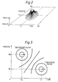
- the rectangular contour 2 which is shown illustrates, for comparison purposes, the effect of a conventional thresholding technique which simply makes a true/false decision depending upon whether or not C and M are within a range of values spanning the target colour.
- a conventional thresholding technique which simply makes a true/false decision depending upon whether or not C and M are within a range of values spanning the target colour.
- any combination of C and M within the rectangle result in a mask value 1, anywhere outside the rectangle result in a mask value 0.
- the region in colour space can be restricted to an ellipse so that points that were included in the corners of the rectangle will now be excluded.
- Figure 2 illustrates the form of the function defined by equation (2) above with the Z-axis representing the magnitude of the function.
- Figure 3 illustrates an example of the function defined in equation (5) above in two dimensions.
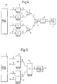
- Figure 4 illustrates a first embodiment of a hardware arrangement for implementing the method.
- respective colour components C, M, Y and K of pixel data in the image store 100 are fed to four look-up tables 3-6 (L1-L4), each having 256 addressable entries with an 8-bit data value stored at each entry.
- the outputs from the look-up tables 3, 4 are fed to an adder 7 while the outputs from the look-up tables 5, 6 are fed to an adder 8.
- the 9-bit outputs from the adders 7, 8 are fed to an adder 9 whose 10-bit output is used to address a look-up table 10 having 1024 entries, each containing an 8-bit mask value, which is stored in the corresponding pixel location in mask store 17.
- Figure 5 illustrates an alternative circuit, which is functionally almost identical to the circuit in Figure 4.
- the colour component data C, M and Y, K are fed in pairs from the image store 1 to look-up tables 11, 12 (L10,L11) each of which has dimensions 64K x 8.
- the outputs from the look-up tables 11, 12 are fed to a further look-up table 13 (L12) to generate the final 8 bit value for storage in the mask store 17.
- the advantage of this arrangement is that the adders are omitted allowing more complex two-dimensional functions to be represented (e.g. ellipses with rotated axes).
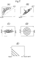
- the user will first define the target colour. This may involve, for example, displaying the image (Fig. 6A) on a monitor and then defining regions in the image having the colour which it is desired to mask.
- a colour-selective mask for the boy's T-shirt is required so that the operator might circle two regions 14, 15 using a cursor or the like and then a further region 16 corresponding to an area which is not to be masked.
- the computer then "plots" all the pixels within the contours 14-16 in colour space and constructs a histogram for the distribution within each colour coordinate as illustrated in Fig. 6B. This histogram is then analysed to determine the median and given percentile points (in this case 10% and 90%) in each colour channel as shown in Fig 6B. The mean is used to define the colour component values of the target colour as shown.
- the operator then instructs the computer to perform the appropriate algorithm as defined by the look-up tables of either the Figure 4 or Figure 5 circuit.
- the resultant mask is then stored in a store 17.
- the operator could subsequently apply a simple threshold operation to the 8-bit data in mask store 17, displaying pixels of the mask where the value exceeds the threshold level by a distinctive colour such as bright green. Interactive adjustment of the threshold level would allow the operator to use judgement as to the optimum setting.
- LCH perceptual colour attributes of lightness, colorfulness and hue
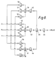
- the initial CMY values are thus applied to respective sets of three of the look-up tables 50-58 which in the first section will convert these colour components to new colour values C', M', Y', to define a set of elliptical contours aligned to the diagonal as shown in Figure 7B.
- the target point is now on the diagonal of the colour cube while the black and white points stay unchanged.
- the actual transformation is conveniently performed by scaling by linear amounts above and below the target colour, ie. by fitting straight lines from the target colour to the white and black points respectively.
- This introduces a geometric discontinuity at the target point, although in most instances this causes no visible discontinuity in the final mask.
- This discontinuity could be eliminated by fitting a higher order curve, such as a parabola, through the target to the white and black points.
- the X' axis approximates the lightness dimension in a perceptual colour space
- the Y', Z' axes approximate the opponent red-green and yellow-blue dimensions respectively.
- the new axes are scaled by respective, different amounts, an origin shift is performed and the resulting component values are squared.
- the output values of these look-up tables 62-64 are reduced to eight bits and then fed to a summation circuit 65 and thence to an output look-up table 66 which may be loaded with a square-root or other function to derive the 8-bit mask value, in similar fashion to LUT 10 of Figure 4.
Description
i.e. if (C1 AND M1 AND Y1 AND K1)
OR (C2 AND M2 AND Y2 AND K2)
OR (C3 AND M3 AND Y3 AND K3)
OR (C4 AND M4 AND Y4 AND K4) is TRUE.
| L1 | Xi = (i-CT)2/N2 | i = (0..255) |
| L2 | Xi = (i-MT)2/N2 | i = (0..255) |
| L3 | Xi = (i-YT)2/N2 | i = (0..255) |
| L4 | Xi = (i-KT)2/N2 | i = (0..255) |
| L5 | Xi = 8√i | i = (0..1023) |
| L1 - L4 | Xi = a . log(fN(i)) |
| L5 | Xi = exp(i/a) |

Claims (9)
- A method of generating an array of control data for use as a mask for processing an image, the array having a number of pixels each of which corresponds to a respective pixel in an image, the method comprising selecting at least one target colour, and then for each control data array pixel generating a control value in accordance with a predetermined algorithm which defines the control value as a function of the corresponding image pixel colour components and the corresponding colour component(s) of the target colour(s), the function defining an ellipsoidal region in the colour space of the colour components wherein the generated control values can be ordered on a scale of at least three value classes to define a multi-bit mask and wherein the step of defining the target colour comprises specifying an area of interest (14-16) within the image; constructing histograms of the colour components of the pixel values within the specified area of interest and determining from the histograms the median and given percentile points for each colour component, and thereby providing the target colour weighting and spread coefficients for the predetermined algorithm.
- A method according to claim 1, wherein the predetermined algorithm defines the control value as representing a function of the Euclidean distance in colour space between the image pixel colour and the target colour.
- A method according to claim 2, wherein the predetermined algorithm has the formCT, MT, YT, and KT are the colour component values of the target colour,C, M, Y, K, are the colour component values of the image pixel, anda, b, c, and d are weighting coefficients.
- A method according to claim 1 or claim 2, wherein the predetermined algorithm has the forma is a normalising factorand b, c govern the widths of the distributions for C,M.
- A method according to claim 1 or claim 2, wherein the predetermined algorithm has the formfF is the foreground functionfB is the background functionand f0 is a constant
- A method according to any of the preceding claims, further comprising a preliminary step in which the initial colour components defining the image in a first colour space are transformed into a second or subsequent colour space from which the control values can be determined.
- A method according to claim 6, wherein the first colour space is transformed so that the colour components defining the central locus of the target colour range lie along the major axis of the second colour space, with the other two axes being perpendicular to the first axis and to each other.
- Apparatus for generating an array of control data for use as a mask for processing an image, the array having a number of pixels each of which corresponds to a respective pixel in an image, the apparatus comprising a first store for storing the image data; a second store for storing the control data; and processing means which, for each control data array pixel generates and stores in the second store a control value in accordance with a predetermined algorithm which defines the control value as a function of the corresponding image pixel colour components and the corresponding colour component(s) of at least one preselected target colour, wherein the generated control values can be ordered on a scale of at least three value classes to define a multi-bit mask; characterised in that the function performed by the predetermined algorithm defines an ellipsoidal region in the colour space of the colour components; and in that the processing means preselects a target colour following the specification of an area of interest within the image by constructing histograms of the colour components of the pixel values within the specified area of interest and determining from the histograms the median and given percentile points for each colour component, and thereby providing the target colour weighting and spread coefficients for the predetermined algorithm.
- Apparatus according to claim 8, wherein the processing means comprises four look-up tables each of which defines a function of the form
Applications Claiming Priority (2)
| Application Number | Priority Date | Filing Date | Title |
|---|---|---|---|
| GB9002477 | 1990-02-05 | ||
| GB909002477A GB9002477D0 (en) | 1990-02-05 | 1990-02-05 | Improvements relating to control data arrays |
Publications (2)
| Publication Number | Publication Date |
|---|---|
| EP0441558A1 EP0441558A1 (en) | 1991-08-14 |
| EP0441558B1 true EP0441558B1 (en) | 1998-01-07 |
Family
ID=10670412
Family Applications (1)
| Application Number | Title | Priority Date | Filing Date |
|---|---|---|---|
| EP91300862A Expired - Lifetime EP0441558B1 (en) | 1990-02-05 | 1991-02-04 | Improvements relating to control data arrays |
Country Status (5)
| Country | Link |
|---|---|
| US (1) | US5105469A (en) |
| EP (1) | EP0441558B1 (en) |
| JP (1) | JP2969010B2 (en) |
| DE (1) | DE69128548T2 (en) |
| GB (1) | GB9002477D0 (en) |
Cited By (1)
| Publication number | Priority date | Publication date | Assignee | Title |
|---|---|---|---|---|
| US6856704B1 (en) | 2000-09-13 | 2005-02-15 | Eastman Kodak Company | Method for enhancing a digital image based upon pixel color |
Families Citing this family (31)
| Publication number | Priority date | Publication date | Assignee | Title |
|---|---|---|---|---|
| GB9009722D0 (en) * | 1990-05-01 | 1990-06-20 | Crosfield Electronics Ltd | Improvements relating to colour vignettes |
| US5282046A (en) * | 1990-07-25 | 1994-01-25 | Brother Kogyo Kabushiki Kaisha | Color image forming apparatus having a color-correcting unit |
| US5237409A (en) * | 1990-09-10 | 1993-08-17 | Brother Kogyo Kabushiki Kaisha | Color image forming apparatus using color compressed color data |
| US5202935A (en) * | 1990-10-19 | 1993-04-13 | Matsushita Electric Industrial Co., Ltd. | Color conversion apparatus for altering color values within selected regions of a reproduced picture |
| JPH04156779A (en) * | 1990-10-19 | 1992-05-29 | Matsushita Electric Ind Co Ltd | Color converter |
| US5295202A (en) * | 1991-08-19 | 1994-03-15 | Eastman Kodak Company | Method and apparatus for replicating a two-color original image with foreground and background colors exchanged |
| CA2077324C (en) * | 1991-10-07 | 1997-06-24 | Michael R. Campanelli | Image editing system and method having improved automatic object selection |
| US5515172A (en) * | 1993-07-19 | 1996-05-07 | Xerox Corporation | Apparatus and method for enhanced color to color conversion |
| US5664171A (en) * | 1994-04-14 | 1997-09-02 | International Business Machines Corporation | System and method for query optimization using quantile values of a large unordered data set |
| EP0693738A3 (en) * | 1994-06-23 | 1996-11-06 | Dainippon Screen Mfg | Method and apparatus for generating color image mask |
| US5880738A (en) * | 1994-08-11 | 1999-03-09 | Canon Information Systems Research Australia Pty Ltd. | Color mapping system utilizing weighted distance error measure |
| AUPM822194A0 (en) * | 1994-09-16 | 1994-10-13 | Canon Inc. | Utilisation of scanned images in an image compositing system |
| JP3400888B2 (en) * | 1995-03-29 | 2003-04-28 | 大日本スクリーン製造株式会社 | How to change the color of a color image |
| DE69601592T2 (en) * | 1995-05-03 | 1999-09-16 | Agfa Gevaert Nv | Hue areas applied selective color correction |
| US5815645A (en) * | 1996-07-29 | 1998-09-29 | Eastman Kodak Company | Method of combining two digital images |
| GB9619119D0 (en) * | 1996-09-12 | 1996-10-23 | Discreet Logic Inc | Processing image |
| US6249315B1 (en) | 1997-03-24 | 2001-06-19 | Jack M. Holm | Strategy for pictorial digital image processing |
| EP1619875A1 (en) | 1997-06-17 | 2006-01-25 | Seiko Epson Corporation | Image processing apparatus, image processing method, color adjustment method, and color adjusment system |
| US6108658A (en) * | 1998-03-30 | 2000-08-22 | International Business Machines Corporation | Single pass space efficent system and method for generating approximate quantiles satisfying an apriori user-defined approximation error |
| JP3845854B2 (en) * | 1998-05-21 | 2006-11-15 | ノーリツ鋼機株式会社 | Image processing method and image processing apparatus |
| US6343288B1 (en) | 1999-03-12 | 2002-01-29 | International Business Machines Corporation | Single pass space efficient system and method for generating an approximate quantile in a data set having an unknown size |
| US6775028B1 (en) | 2000-02-24 | 2004-08-10 | Lexmark International, Inc. | Non-linear method of mapping the lightness and chroma of a display device gamut onto a printing device gamut |
| US6894806B1 (en) | 2000-03-31 | 2005-05-17 | Eastman Kodak Company | Color transform method for the mapping of colors in images |
| US6456297B1 (en) * | 2000-05-10 | 2002-09-24 | Adobe Systems Incorporated | Multipole brushing |
| CA2347181A1 (en) | 2000-06-13 | 2001-12-13 | Eastman Kodak Company | Plurality of picture appearance choices from a color photographic recording material intended for scanning |
| US6781724B1 (en) * | 2000-06-13 | 2004-08-24 | Eastman Kodak Company | Image processing and manipulation system |
| EP1694051A4 (en) * | 2003-12-11 | 2010-11-17 | Fujitsu Ltd | Image processing method, program, and device |
| US7715620B2 (en) * | 2006-01-27 | 2010-05-11 | Lockheed Martin Corporation | Color form dropout using dynamic geometric solid thresholding |
| GB2437338A (en) * | 2006-04-21 | 2007-10-24 | Snell & Wilcox Ltd | Detecting monochrome images from the skew of a statistical distribution of pixel values |
| DE602007012270D1 (en) * | 2007-11-16 | 2011-03-10 | Honda Res Inst Europe Gmbh | Method and apparatus for continuous object-background segmentation in images from dynamic visual scenes |
| KR101451134B1 (en) * | 2010-02-12 | 2014-10-15 | 삼성테크윈 주식회사 | Method for anti aliasing of font |
Citations (2)
| Publication number | Priority date | Publication date | Assignee | Title |
|---|---|---|---|---|
| EP0159691A2 (en) * | 1984-04-27 | 1985-10-30 | International Business Machines Corporation | Color image display system |
| EP0344976A1 (en) * | 1988-05-31 | 1989-12-06 | Crosfield Electronics Limited | Image generating apparatus |
Family Cites Families (6)
| Publication number | Priority date | Publication date | Assignee | Title |
|---|---|---|---|---|
| JPS55142345A (en) * | 1979-04-23 | 1980-11-06 | Dainippon Screen Mfg Co Ltd | Masking operation method in digital color tone control |
| US4488245A (en) * | 1982-04-06 | 1984-12-11 | Loge/Interpretation Systems Inc. | Method and means for color detection and modification |
| JPS60123978A (en) * | 1983-12-08 | 1985-07-02 | Kubota Ltd | Chrominance signal separating device |
| US4642683A (en) * | 1985-05-06 | 1987-02-10 | Eastman Kodak Company | Digital image processing method for images with bimodal tone value distribution |
| US4878178A (en) * | 1985-12-25 | 1989-10-31 | Sharp Kabushiki Kaisha | Image processing device |
| JPS6429079A (en) * | 1987-07-24 | 1989-01-31 | Nippon Denki Home Electronics | Chrominance signal correction system |
-
1990
- 1990-02-05 GB GB909002477A patent/GB9002477D0/en active Pending
-
1991
- 1991-02-04 DE DE69128548T patent/DE69128548T2/en not_active Expired - Fee Related
- 1991-02-04 EP EP91300862A patent/EP0441558B1/en not_active Expired - Lifetime
- 1991-02-05 US US07/650,492 patent/US5105469A/en not_active Expired - Lifetime
- 1991-02-05 JP JP3100556A patent/JP2969010B2/en not_active Expired - Fee Related
Patent Citations (2)
| Publication number | Priority date | Publication date | Assignee | Title |
|---|---|---|---|---|
| EP0159691A2 (en) * | 1984-04-27 | 1985-10-30 | International Business Machines Corporation | Color image display system |
| EP0344976A1 (en) * | 1988-05-31 | 1989-12-06 | Crosfield Electronics Limited | Image generating apparatus |
Cited By (1)
| Publication number | Priority date | Publication date | Assignee | Title |
|---|---|---|---|---|
| US6856704B1 (en) | 2000-09-13 | 2005-02-15 | Eastman Kodak Company | Method for enhancing a digital image based upon pixel color |
Also Published As
| Publication number | Publication date |
|---|---|
| GB9002477D0 (en) | 1990-04-04 |
| DE69128548D1 (en) | 1998-02-12 |
| JPH04227585A (en) | 1992-08-17 |
| EP0441558A1 (en) | 1991-08-14 |
| JP2969010B2 (en) | 1999-11-02 |
| US5105469A (en) | 1992-04-14 |
| DE69128548T2 (en) | 1998-04-16 |
Similar Documents
| Publication | Publication Date | Title |
|---|---|---|
| EP0441558B1 (en) | Improvements relating to control data arrays | |
| Plataniotis et al. | Color image processing and applications | |
| EP0264281B1 (en) | Color-matched printing | |
| US7400763B2 (en) | Smart erasure brush | |
| US5231504A (en) | Method for improved color reproduction using linear mixing calculations based on positional relationships between an original color and an achromatic region in a linear mixing space | |
| US20100284030A1 (en) | Color conversion apparatus, color conversion method, color change program and recording medium | |
| US6208351B1 (en) | Conversion of alpha-multiplied color data | |
| US6226010B1 (en) | Color selection tool | |
| EP0873552A1 (en) | Processing image data | |
| JPH04234261A (en) | Method of projecting color image onto monochrome image | |
| US20010014175A1 (en) | Method for rapid color keying of color video images using individual color component look-up-tables | |
| EP0732844B1 (en) | Contrast correcting apparatus | |
| JP3449860B2 (en) | Image sharpness processing device | |
| US6115078A (en) | Image sharpness processing method and apparatus, and a storage medium storing a program | |
| US6185013B1 (en) | Color printing having a plural highlight color image map in a full color image | |
| US5442717A (en) | Sharpness processing apparatus | |
| EP0741492A1 (en) | Selective colour correction applied to plurality of local color gamuts | |
| Ebner et al. | Gamut mapping from below: Finding minimum perceptual distances for colors outside the gamut volume | |
| US6456295B1 (en) | Method for simulating diffusion on a raster | |
| JP3482106B2 (en) | Luminance image generation method and apparatus, and recording medium recording this method | |
| US6295369B1 (en) | Multi-dimensional color image mapping apparatus and method | |
| Zhang et al. | Color Image Processing | |
| JP3105689B2 (en) | Image processing apparatus and method | |
| Safibullaevna et al. | Processing Color Images, Brightness and Color Conversion | |
| Chambah et al. | Approach to Automate Digital Restoration of Faded Color Films |
Legal Events
| Date | Code | Title | Description |
|---|---|---|---|
| PUAI | Public reference made under article 153(3) epc to a published international application that has entered the european phase |
Free format text: ORIGINAL CODE: 0009012 |
|
| AK | Designated contracting states |
Kind code of ref document: A1 Designated state(s): DE GB |
|
| 17P | Request for examination filed |
Effective date: 19920213 |
|
| RAP1 | Party data changed (applicant data changed or rights of an application transferred) |
Owner name: CROSFIELD ELECTRONICS LIMITED |
|
| 17Q | First examination report despatched |
Effective date: 19960513 |
|
| GRAG | Despatch of communication of intention to grant |
Free format text: ORIGINAL CODE: EPIDOS AGRA |
|
| GRAG | Despatch of communication of intention to grant |
Free format text: ORIGINAL CODE: EPIDOS AGRA |
|
| GRAH | Despatch of communication of intention to grant a patent |
Free format text: ORIGINAL CODE: EPIDOS IGRA |
|
| GRAH | Despatch of communication of intention to grant a patent |
Free format text: ORIGINAL CODE: EPIDOS IGRA |
|
| GRAA | (expected) grant |
Free format text: ORIGINAL CODE: 0009210 |
|
| AK | Designated contracting states |
Kind code of ref document: B1 Designated state(s): DE GB |
|
| REF | Corresponds to: |
Ref document number: 69128548 Country of ref document: DE Date of ref document: 19980212 |
|
| REG | Reference to a national code |
Ref country code: GB Ref legal event code: 732E |
|
| PLBE | No opposition filed within time limit |
Free format text: ORIGINAL CODE: 0009261 |
|
| STAA | Information on the status of an ep patent application or granted ep patent |
Free format text: STATUS: NO OPPOSITION FILED WITHIN TIME LIMIT |
|
| 26N | No opposition filed | ||
| REG | Reference to a national code |
Ref country code: GB Ref legal event code: IF02 |
|
| PGFP | Annual fee paid to national office [announced via postgrant information from national office to epo] |
Ref country code: GB Payment date: 20030129 Year of fee payment: 13 |
|
| PGFP | Annual fee paid to national office [announced via postgrant information from national office to epo] |
Ref country code: DE Payment date: 20030213 Year of fee payment: 13 |
|
| PG25 | Lapsed in a contracting state [announced via postgrant information from national office to epo] |
Ref country code: GB Free format text: LAPSE BECAUSE OF NON-PAYMENT OF DUE FEES Effective date: 20040204 |
|
| PG25 | Lapsed in a contracting state [announced via postgrant information from national office to epo] |
Ref country code: DE Free format text: LAPSE BECAUSE OF NON-PAYMENT OF DUE FEES Effective date: 20040901 |
|
| GBPC | Gb: european patent ceased through non-payment of renewal fee |
Effective date: 20040204 |