EP0442275A2 - Device for detecting a vessel put in the heating zone of a cooking or heating apparatus - Google Patents
Device for detecting a vessel put in the heating zone of a cooking or heating apparatus Download PDFInfo
- Publication number
- EP0442275A2 EP0442275A2 EP91100507A EP91100507A EP0442275A2 EP 0442275 A2 EP0442275 A2 EP 0442275A2 EP 91100507 A EP91100507 A EP 91100507A EP 91100507 A EP91100507 A EP 91100507A EP 0442275 A2 EP0442275 A2 EP 0442275A2
- Authority
- EP
- European Patent Office
- Prior art keywords
- sensor
- cooking
- heating
- value
- evaluation means
- Prior art date
- Legal status (The legal status is an assumption and is not a legal conclusion. Google has not performed a legal analysis and makes no representation as to the accuracy of the status listed.)
- Granted
Links
Images

Classifications
-
- H—ELECTRICITY
- H05—ELECTRIC TECHNIQUES NOT OTHERWISE PROVIDED FOR
- H05B—ELECTRIC HEATING; ELECTRIC LIGHT SOURCES NOT OTHERWISE PROVIDED FOR; CIRCUIT ARRANGEMENTS FOR ELECTRIC LIGHT SOURCES, IN GENERAL
- H05B3/00—Ohmic-resistance heating
- H05B3/68—Heating arrangements specially adapted for cooking plates or analogous hot-plates
- H05B3/74—Non-metallic plates, e.g. vitroceramic, ceramic or glassceramic hobs, also including power or control circuits
- H05B3/746—Protection, e.g. overheat cutoff, hot plate indicator
-
- H—ELECTRICITY
- H05—ELECTRIC TECHNIQUES NOT OTHERWISE PROVIDED FOR
- H05B—ELECTRIC HEATING; ELECTRIC LIGHT SOURCES NOT OTHERWISE PROVIDED FOR; CIRCUIT ARRANGEMENTS FOR ELECTRIC LIGHT SOURCES, IN GENERAL
- H05B2213/00—Aspects relating both to resistive heating and to induction heating, covered by H05B3/00 and H05B6/00
- H05B2213/05—Heating plates with pan detection means
Definitions
- the object of the invention is to create a device in which the arrangement of the sensor in the heating zone is unproblematic and in the most varied Operating conditions allows a clear detection of a set pot. This object is solved by claim 1.
- the dependency of the detection on the signal change avoids the setting of a certain absolute value for the switching point, so that changing basic requirements, e.g. B. changed by the influence of temperature characteristics of the sensor can be taken into account.
- the dependency on the rate of change makes it possible to select the response speed of the pot detection to be greater than the rate of change of the basic values.
- inductive sensors could only be used with poor results because they had to be temperature-shielded and therefore had to be too far away from the actual hotplate.
- they can be arranged largely directly at the heating point, for. B. at the edge or in the middle of the heating zone and especially just below the actual cooking surface, closer to this than z. B. radiant heating elements.
- a material which has proven to be particularly advantageous for an inductive sensor as a material which is resistant to high temperatures has hitherto not been considered suitable for such purposes, namely an electrically insulating oxidized heating conductor material, for example a chromium-nickel alloy Art Ni Cr 7030.
- This material which is known as a heating conductor material, was considered unusable due to its high resistance value for induction coils, above all because a ferromagnetic coil core must be dispensed with for temperature reasons. Temperatures up to 1300 K (approx. 1000 degrees Celsius) can occur in the area of the induction coil, while conventional coil materials can only withstand a fraction of these temperatures.
- the evaluation means can work analogously and determine the rate of change by differentiating the output sensor signal.
- the evaluation means can particularly advantageously work digitally, the starting point being a comparison of the pulses of a sensor resonant circuit frequency counted over a certain gate time with a comparison number, which is kept at a distance in each case from the sensor-dependent pulse number by a certain threshold value.
- the comparison number is adapted to the actual value of the number dependent on the sensor frequency in each case in a predetermined time sequence, so that the threshold value has a certain size or, depending on the case, also an absolute value of the sensor signal in all operating states.
- the sign of the threshold value is changed depending on the detection (pot present / not available).
- the readjustment to the threshold value which is supposed to take place slowly in order to be able to use even weak values, could be accelerated by shortening the readjustment time.
- This can be achieved by a readjustment speed that is directly dependent on the size of the respective difference value.
- a microcontroller is particularly suitable for implementation, i. H. a programmable module that works digitally like a computer, as is often used in control systems. At the same time, it could also contain the functions of an adjustable power control device, a temperature-dependent control device and / or other control functions, such as for a parboil, for temperature limitation, etc., so that apart from control sensors, normally only a code transmitter for manual setting and a power Switching component (relay, triac or the like) are necessary to implement the entire control of the cooking device.
- the setup is possible with various sensor systems, including capacitive, optical or similar sensors.
- sensor types including capacitive, optical or similar sensors.
- the device should have a bypass or a switch-off device that enables the cooking device to be operated independently of the pan detection. It can be time-controlled so that it switches back to automatic pot detection after a certain time.
- the previously described functional sequence could also be used. Instead of the pulse counting and the difference formation from these values, there would be a difference (beat) between the sensor frequency and one correspondingly adjusted comparison frequency can be used.
- the device can also be implemented as a user-specific integrated circuit (ASIC).
- the invention provides further advantages, above all increased safety, because it prevents a hotplate from being operated in idle mode after the cooking appliance has been removed.
- the inductive version which is dependent on a ferromagnetic material in the cooking vessel, has the additional safety advantage that it does not respond, for example, when a plastic container is placed on the hotplate, which would be possible with optical devices.
- FIG. 1 shows part of a cooking appliance 11 with radiant heater 13 arranged under a glass ceramic plate 12. It contains, in a sheet metal carrier shell 14, heat-resistant insulation 15 with a peripheral edge 16 supported on the glass ceramic plate 12 and an annular recess 17 on the bottom thereof for example, radiant heating resistors 18 designed as a heating winch are arranged spirally surrounding a central zone 19.
- radiant heaters 13 are pressed resiliently onto the underside of a glass ceramic plate 12 and form individual heating zones 20. They are also suitable for heating or other purposes.
- the central zone 19 is formed by an upwardly projecting section of the insulation 15.
- a recess 21 is provided in it, in which a sensor coil 22 is located.
- the recess is closed at the top by a disk 23 made of a temperature-resistant insulating material which is firmer than the insulating material 15 and which is supported on the underside of the glass ceramic plate 12.
- the coil 22 is therefore in a room shielded from direct heat radiation from the radiators.
- the also electrically insulating disk 23 ensures that contact with live parts is excluded, since glass ceramic becomes conductive at operating temperatures. It also protects the edges of the central zone from damage.
- the coil is thus just below the glass ceramic plate and closer to it than the heating resistors 18 and also at a central point.
- Fig. 2 differs from Fig. 1 only in that there Insulation 15 of the radiant heater 13 has a bowl or shell shape without a protruding central zone.
- the sensor coil 22 extends all the way around the radiant heater and is arranged in a circumferential groove 24 provided from the outside in the upper part of the edge 16 of the insulation.
- An annular disk 23 is inserted between the glass ceramic plate 12 and the rim 16 and has a mechanical and electrical protective function.
- the groove could also be an angular edge recess, ie without the interposition of part of the insulating body 15 between the coil and the disk.
- the coil is protected against direct exposure to the radiant heating. Nevertheless, considerable temperatures occur there.
- the coil is made of a material that, including its insulation, is resistant to over 1300 K (approx. 1000 degrees C). It is preferably a chromium-nickel alloy of the type Ni Cr 7030. It is electrically insulated by oxidizing its outer surface. However, this material has a rather high electrical resistance. It can therefore have only a few revolving turns, in particular in the case of an embodiment according to FIG. 2. Because of the lack of a ferromagnetic coil core, the coil quality is therefore low. After all, this material enables use directly in the area of the heating zone, possibly even closer to the heating resistors or between them and the glass ceramic plate.
- the coil 22 is the sensor of a device for recognizing a cooking vessel 25 set up in the heating zone, which also includes objects to be heated, roasting, heating or other vessels.
- the sensor responds to such cooking vessels if they are off a material that changes its inductance (ferromagnetic material) or contain it.
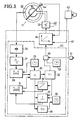
- the sensor coil 22 generates an output signal in the form of an inductance change when there is a change in the induction of its surroundings caused by the installation of a cooking vessel 25. It is part of an oscillating circuit whose remaining parts, for example a capacitance, are contained in a signal input element 26. The signal is then converted into a square wave signal in a signal converter 27, i.e. a square wave frequency is produced from the sinusoidal oscillation frequency, which is more suitable for further digital processing. In the subsequent frequency measuring device 28, the number of pulses of the square-wave signal and thus a number representing an oscillation frequency is determined and stored via a specific gate time specified by a timer 29.
- This pulse number which is dependent on the sensor frequency, is fed to a difference-forming device 30, where it is compared with a corresponding comparison number, which comes from a comparison number memory and is formed there, as described later.
- a signal corresponding to the resulting difference is sent to logic logic 32, including the sign of the difference.
- the logic logic 32 also contains a memory for a desired distance or threshold value, below which an output signal is given to the switching means 33, possibly via a control or control device 34 explained later. In practice, depending on the current operating state (cooking vessel available / not available) or cooking appliance on / off) corresponding to the threshold value Number added or subtracted from the difference, so that a corresponding enable signal is generated at each zero crossing.
- the comparison number which is stored in the memory 31, is the respective actual value, i.e. the number corresponding to the sensor frequency, adapted or tracked. With the aim of obtaining a certain target distance or a target difference. For this purpose, when the actual value and thus the difference value change, a certain amount is added or subtracted from the comparison number in the memory 31 per cycle (gate time interval) via an adaptation device 35 (depending on the +/- sign in the memory of the logic logic 32). The comparison number is thereby adjusted in the direction of the actual value, i.e. tracked until the differential setpoint is reached. As a result, the same response threshold is always achieved regardless of the absolute size of the signal present.
- the described switching means belong to the evaluation means 40, as symbolized in FIG. 3 by the dashed frame. In the exemplary embodiment, most work digitally. They can be part of a microcontroller 41 or microcomputer, including the regulating or control device 34.
- the individual devices and elements described for explanation in FIG. 3 are not physically contained therein, but are replaced by appropriate programming in order to carry out the functions described. This also applies to the function of the regulating or control device 34, which also carries out the switching on / off also functions such as power setting, temperature, monitoring and / or regulation etc. It also receives an output signal from the evaluation means 40, possibly signals from a code transmitter 42, which e.g.
- the switching means 43 can be a binary transmitter actuated by a setting button, and / or by a temperature measuring and / or switching device 44.
- the switching means 43 switch the voltage of the household network 45 to the heating resistors 18 on the high current side and can contain a mechanical relay or corresponding electronic components.
- the facility works according to the following procedure: If the cooking appliance is ready for operation but its heating is not switched on, the resonant circuit containing the sensor coil 22 is in operation. It generates its specific frequency, which means that the frequency measuring and storage device detects a specific number of pulses during the gate time.
- the associated comparison number from the comparison number memory 31 is a predetermined difference value away from it.
- the inductance of the oscillating circuits operated at a relatively high frequency of, for example, 100 kHz to 1 mHz changes now by placing a cooking vessel
- the actual number also changes, which is determined by the frequency measuring device during the gate time and is supplied to the difference 30. If this exceeds the threshold value, then in the logic logic 32 there is a zero crossing in the manner described above, and for example a positive output signal is generated which switches on the heating 18 via the control unit 34 and the switching means 33.
- a gradual, relatively slow adjustment of the comparison value to the current actual values is now carried out per cycle via the adaptation device 35. If, for example, a very strongly ferromagnetic pot was used, which caused a large change in inductance, the setpoint distance may not be reached within a predetermined time set by the timer 36, so that the jump device 37 makes an abrupt adjustment by changing the comparison value to the specified inch distance from the actual value is set. This means that even after a relatively short time, the evaluation device is again able to respond even to smaller changes in inductance, for example after a strongly ferromagnetic pot has been removed by placing a little ferromagnetic pot on it.
- the inductance properties of the sensor coil 22 change greatly as a result of heat and other environmental influences.
- the high-temperature-resistant trace material has a strongly positive resistance characteristic, which leads to a significant drift in the inductance values without spatial changes in the cooking pot / heating zone assignment leads. Since these changes in the absolute values take place in a time range that differs significantly from the placement or removal of a pot, the adjustment of the comparison value via the adjustment device 35 can easily follow this change and set the respective threshold value interval again without that the evaluation unit is triggered. It only reacts to changes that occur faster than the adaptation, so that the sensitivity of the device can also be predetermined via the adaptation speed.
- the evaluation means also contain a temporary switch-off device 50 which was actuated by the user, for example via a push button 51. With it, the user can deactivate the evaluation device for a time specified by a timer 53 in its effect on the switching means 33, for example if he wants to cook with a glass ceramic tableware.
- the schematic circuit diagram indicates that the output signal of the logic logic 32 is suppressed.
- this switch-off device could also be implemented in another way, for example by switching off the entire evaluation device, by bridging the switching means 33 or the like on the high current side. However, it is important that after a certain time (timer 53) this switch-off of the pot detection is canceled again is going to automatic pot detection to return and thus to restart the advantageous function and safety effect.
- Manual control can also be done using a conventional on / off switch, which is automatically reset after the given time. Since the automatic pot detection can not only lead to increased operational safety, but also to considerable energy savings, it is very suitable not only for domestic stoves, but above all also for commercial kitchens. There, the usual running through of the cooking appliances is avoided throughout the day and, in conjunction with a low-capacity heating, the same result is achieved without delay for the cook. An additional advantage is the lower heat development and thus improved working conditions for the kitchen staff.
Abstract
Description
Es ist schon versucht worden, Topferkennungssysteme zu schaffen, die ein Kochgerät nur bei Vorhandensein eines Topfes in der Heizzone einschalten. Bekannt sind Systeme mit optischen Fühlern und teilweise mit Helligkeitsvergleich (DE-A 35 33 997 und 33 27 622) und mit induktiven Fühlern (DE-A 37 11 589 und 37 33 108). Bei allen diesen Systemen war die Anordnung des Sensors in der beheizten Zone problematisch. Sensoren, die die hohen Temperaturen aushalten, sind meist zu unempfindlich, um Nutz- von Störsignalen trennen zu können, insbesondere, weil die Töpfe ein sehr unterschiedliches Verhalten im Sensorfeld haben.Attempts have already been made to create pan detection systems which only switch on a cooking appliance when there is a pot in the heating zone. Systems with optical sensors and partially with brightness comparison (DE-A 35 33 997 and 33 27 622) and with inductive sensors (DE-A 37 11 589 and 37 33 108) are known. The arrangement of the sensor in the heated zone was problematic in all of these systems. Sensors that can withstand the high temperatures are usually too insensitive to separate useful and interference signals, especially because the pots behave very differently in the sensor field.
Erfindungsaufgabe ist die Schaffung einer Einrichtung, bei der die Anordnung des Fühlers in der Heizzone unproblematisch ist und die bei den unterschiedlichsten Betriebsbedingungen eine klare Erkennung eines aufgestellten Topfes ermöglicht. Diese Aufgabe wird durch den Anspruch 1 gelöst.The object of the invention is to create a device in which the arrangement of the sensor in the heating zone is unproblematic and in the most varied Operating conditions allows a clear detection of a set pot. This object is solved by claim 1.
Die Abhängigkeit der Erkennung von der Signaländerung vermeidet die Einstellung eines bestimmten Absolutwertes für den Schaltpunkt, so daß auch sich ändernde Basisvoraussetzungen, z. B. durch Temperatureinfluß geänderte Charakteristika des Sensors, berücksichtigt werden können. Die Abhängigkeit von der Änderungsgeschwindigkeit ermöglicht es, die Ansprechgeschwindigkeit der Topferkennung größer zu wählen als die Änderungsgeschwindigkeit der Basiswerte. Diese Einrichtung ermöglicht die Erkennung von Töpfen, die so geringe Sensorsignaländerungen hervorrufen, daß sie nicht größer oder sogar kleiner sind als die Änderung der Sensorcharakteristika. Da sich diese Charakteristika aber wesentlich langsamer ändern als die zu erkennende Topfaufstellung, ist eine klare Unterscheidung möglich.The dependency of the detection on the signal change avoids the setting of a certain absolute value for the switching point, so that changing basic requirements, e.g. B. changed by the influence of temperature characteristics of the sensor can be taken into account. The dependency on the rate of change makes it possible to select the response speed of the pot detection to be greater than the rate of change of the basic values. This device enables the detection of pots which cause such small changes in sensor signals that they are no larger or even smaller than the change in the sensor characteristics. However, since these characteristics change much more slowly than the pot position to be recognized, a clear distinction is possible.
Damit ist ein großer Bereich an möglichen Sensoren eröffnet worden, die bisher kaum einsetzbar waren. In der Praxis konnten induktive Sensoren nur mit schlechten Ergebnissen eingesetzt werden, weil sie temperaturabgeschirmt und damit zu weit von der eigentlichen Kochstelle entfernt liegen mußten. Erfindungsgemäß können sie weitgehend direkt an der Heizstelle angeordnet sein, z. B. am Rand oder in der Mitte der Heizzone und vor allem dicht unterhalb der eigentlichen Kochfläche, näher an dieser als z. B. Strahlheizelemente. Als besonders vorteilhaft hat sich für einen induktiven Sensor als Material ein hochtemperaturbeständiges Material erwiesen, daß bisher für derartige Zwecke nicht als einsetzbar gegolten hat, nämlich ein elektrisch isolierend oxidiertes Heizleitermaterial, z.B. eine Chromnickel-Legierung der Art Ni Cr 7030. Dieses Material, das zwar als Heizleitermaterial bekannt ist, galt aufgrund seines hohen Widerstandswertes für Induktionsspulen als unbrauchbar, vor allem, weil hierbei aus Temperaturgründen auf einen ferromagnetischen Spulenkern verzichtet werden muß. Im Bereich der Induktionsspule können Temperaturen bis zu 1300 K (ungefähr 1000 Grad Celsius) auftreten, während übliche Spulenmaterialien nur einen Bruchteil dieser Temperaturen ertragen.This opens up a wide range of possible sensors that were previously difficult to use. In practice, inductive sensors could only be used with poor results because they had to be temperature-shielded and therefore had to be too far away from the actual hotplate. According to the invention, they can be arranged largely directly at the heating point, for. B. at the edge or in the middle of the heating zone and especially just below the actual cooking surface, closer to this than z. B. radiant heating elements. A material which has proven to be particularly advantageous for an inductive sensor as a material which is resistant to high temperatures has hitherto not been considered suitable for such purposes, namely an electrically insulating oxidized heating conductor material, for example a chromium-nickel alloy Art Ni Cr 7030. This material, which is known as a heating conductor material, was considered unusable due to its high resistance value for induction coils, above all because a ferromagnetic coil core must be dispensed with for temperature reasons. Temperatures up to 1300 K (approx. 1000 degrees Celsius) can occur in the area of the induction coil, while conventional coil materials can only withstand a fraction of these temperatures.
Nach der Erfindung können die Auswertemittel analog arbeiten und die Änderungsgeschwindigkeit durch eine Differenzierung des Ausgangs- Sensorsignales ermitteln. Besonders vorteilhaft können die Auswertemittel jedoch digital arbeiten, wobei der Ausgangspunkt ein Vergleich der über eine bestimmte Torzeit gezählten Impulse einer Sensor-Schwingkreisfrequenz mit einer Vergleichszahl ist, die jeweils um einen bestimmten Schwellenwert von der sensorabhängigen Impulszahl entfernt gehalten wird. Dabei wird die Vergleichszahl jeweils in einer vorgegebenen Zeitfolge an den Istwert der sensorfrequenzabhängigen Zahl angepaßt, so daß in allen Betriebszuständen der Schwellenwert eine bestimmte oder gegebenfalls auch vom Absolutwert des Sensorsignal abhängige Größe hat. Dabei wird, jeweils abhängig von der Erkennung (Topf vorhanden/nicht vorhanden) das Vorzeichen des Schwellenwertes geändert. Falls die Differenz zwischen dem sensorabhängigen Wert und dem Vergleichswert zu groß wird, könnte die Nachregelung auf den Schwellenwert, die ja, um auch schwache Werte verwerten zu können, langsam erfolgen soll, durch Verkürzung der Nachregelzeit beschleunigt werden. Dies kann durch eine von der Größe des jeweiligen Differenzwertes direkt abhängige Nachregelgeschwindigkeit erreicht werden. Bei der digitalen Ausbildung läßt sich eine einfache und trotzdem sehr gute Anpassung dadurch erzeugen, daß nach anfänglicher Nachregelung mit gleichbleibender Anpassungsgeschwindigkeit diese sprunghaft erfolgt, wenn bis zu einem vorgegebenen Zeitpunkt die Anpassung nicht abgeschlossen ist.According to the invention, the evaluation means can work analogously and determine the rate of change by differentiating the output sensor signal. However, the evaluation means can particularly advantageously work digitally, the starting point being a comparison of the pulses of a sensor resonant circuit frequency counted over a certain gate time with a comparison number, which is kept at a distance in each case from the sensor-dependent pulse number by a certain threshold value. The comparison number is adapted to the actual value of the number dependent on the sensor frequency in each case in a predetermined time sequence, so that the threshold value has a certain size or, depending on the case, also an absolute value of the sensor signal in all operating states. The sign of the threshold value is changed depending on the detection (pot present / not available). If the difference between the sensor-dependent value and the comparison value becomes too large, the readjustment to the threshold value, which is supposed to take place slowly in order to be able to use even weak values, could be accelerated by shortening the readjustment time. This can be achieved by a readjustment speed that is directly dependent on the size of the respective difference value. With digital training, a simple and nevertheless very good one can be Generate the adjustment in such a way that after the initial readjustment with a constant adjustment speed, this takes place suddenly, if the adjustment has not been completed by a predetermined point in time.
Zur Verwirklichung eignet sich besonders ein Mikro-Controller, d. h. ein nach Art eines Rechners digital arbeitender, programmierbarer Baustein, wie er häufig in Steuerungen eingesetzt wird. Er könnte gleichzeitig auch die Funktionen eines einstellbaren Leistungssteuerungsgerätes, eines temperaturabhängigen Regelgerätes und/oder weitere Steuerfunktionen, wie beispielsweise für einen Ankochstoß, für die Temperaturbegrenzung etc. mit enthalten, so daß normalerweise außer Regelfühlern nur noch ein Codegeber für die manuelle Einstellung und ein Leistungs- Schaltbauteil (Relais, Triac o. dgl.) notwendig sind, um die gesamte Steuerung des Kochgerätes zu verwirklichen.A microcontroller is particularly suitable for implementation, i. H. a programmable module that works digitally like a computer, as is often used in control systems. At the same time, it could also contain the functions of an adjustable power control device, a temperature-dependent control device and / or other control functions, such as for a parboil, for temperature limitation, etc., so that apart from control sensors, normally only a code transmitter for manual setting and a power Switching component (relay, triac or the like) are necessary to implement the entire control of the cooking device.
Die Einrichtung ist mit verschiedenen Sensorsystemen möglich, so auch mit kapazitiven, optischen oder ähnlichen Fühlern. Bei einigen Fühlertypen, beispielsweise dem induktiven, werden gewisse Kochgefäßmaterialien nicht erfaßt. Deswegen sollte die Einrichtung eine Überbrückung bzw. eine Abschalteinrichtung besitzen, die eine von der Topferkennung unabhängige Betätigung des Kochgerätes ermöglicht. Sie kann zeitgesteuert sein, so daß nach einer gewissen Zeit wieder auf automatische Topferkennung zurückgeschaltet wird.The setup is possible with various sensor systems, including capacitive, optical or similar sensors. With some sensor types, for example the inductive one, certain cooking vessel materials are not detected. Therefore, the device should have a bypass or a switch-off device that enables the cooking device to be operated independently of the pan detection. It can be time-controlled so that it switches back to automatic pot detection after a certain time.
Bei einer die Signale analog verarbeitenden Einrichtung könnte der vorher beschriebene Funktionsablauf ebenfalls verwendet werden. Dort würde anstelle der Impulszählung und der Differenzbildung aus diesen Werten eine Differenz (Schwebung) zwischen der Sensorfrequenz und einer entsprechend nachgeregelten Vergleichsfrequenz verwendet werden. Die Einrichtung läßt sich auch als Anwender-spezifischer integrierter Schaltkreis (ASIC) verwirklichen.In the case of a device that processes the signals in analog fashion, the previously described functional sequence could also be used. Instead of the pulse counting and the difference formation from these values, there would be a difference (beat) between the sensor frequency and one correspondingly adjusted comparison frequency can be used. The device can also be implemented as a user-specific integrated circuit (ASIC).
Die Erfindung schafft außer der Bedienungsfreundlichkeit weitere Vorteile, vor allem eine erhöhte Sicherheit, weil verhindert wird, daß eine Kochstelle nach Abnehmen des Kochgerätes im Leerlauf weiterbetrieben wird. Die induktive, von einem ferromagnetischen Material im Kochgefäß abhängige Ausführung hat den zusätzlichen Sicherheitsvorteil, daß sie beispielsweise beim Abstellen eines Kunststoffbehälters auf der Kochstelle nicht anspricht, was bei optischen Einrichtungen möglich wäre.In addition to the ease of use, the invention provides further advantages, above all increased safety, because it prevents a hotplate from being operated in idle mode after the cooking appliance has been removed. The inductive version, which is dependent on a ferromagnetic material in the cooking vessel, has the additional safety advantage that it does not respond, for example, when a plastic container is placed on the hotplate, which would be possible with optical devices.
Diese und weitere Merkmale von bevorzugten Weiterbildungen der Erfindung gehen außer aus den Ansprüchen auch aus der Beschreibung und den Zeichnungen hervor, wobei die einzelnen Merkmale jeweils für sich allein oder zu mehreren in Form von Unterkombinationen bei einer Ausführungsform der Erfindung und auf anderen Gebieten verwirklicht sein und vorteilhafte sowie für sich schutzfähige Ausführungen darsstellen können, für die hier Schutz beansprucht wird. Ausführungsbeispiele der Erfindung sind in der Zeichnung dargestellt und werden im folgenden näher erläutert. Es zeigen:
- Fig. 1 und 2
- je einen schematischen Teilschnitt durch ein Kochgerät mit Glaskeramikplatte und einem Strahlheizkörper und
- Fig. 3
- ein schematisches Blockschaltbild einer Topferkennungseinrichtung, wobei die einzelnen Blöcke mit erläuternden Funktionssymbolen versehen sind.
- 1 and 2
- each a schematic partial section through a cooking appliance with glass ceramic plate and a radiant heater and
- Fig. 3
- is a schematic block diagram of a pot detection device, wherein the individual blocks are provided with explanatory function symbols.
Fig. 1 zeigt einen Teil eines Kochgerätes 11 mit unter einer Glaskeramikplatte 12 angeordnetem Strahlheizkörper 13. Er enthält in einer Blech-Trägerschale 14 eine wärmebeständige Isolierung 15 mit einem umlaufenden und an der Glaskeramikplatte 12 abgestütztem Rand 16 und einer ringförmigen Ausnehmung 17, an deren Boden beispielsweise als Heizwinde ausgebildete Strahlheizwiderstände 18 spiralförmig eine Mittelzone 19 umgebend angeordnet sind. Mehrere Strahlheizkörper 13 sind an die Unterseite einer Glaskeramikplatte 12 federnd angedrückt und bilden einzelne Heizzonen 20. Sie sind auch zum Wärmen oder anderen Zwecken geeignet.1 shows part of a
Die Mittelzone 19 wird durch einen nach oben vorspringenden Abschnitt der Isolierung 15 gebildet. In ihr ist eine Ausnehmung 21 vorgesehen, in der eine Sensorspule 22 liegt. Die Ausnehmung ist nach oben durch eine Scheibe 23 aus einem gegenüber dem Isoliermaterial 15 festeren, temperaturbeständigen Isoliermaterial abgeschlossen, die sich an der Unterseite der Glaskeramikplatte 12 abstützt. Die Spule 22 liegt daher in einem gegen direkte Wärmestahlung von den Heizkörpern her abgeschirmten Raum. Die auch elektrisch isolierende Scheibe 23 sorgt dafür, daß Berührung mit stromführenden Teilen ausgeschlossen ist, da Glaskeramik bei Betriebstemperaturen leitend wird. Sie schützt auch die Ränder der Mittelzone vor Beschädigung.The
Es ist zu erkennen, daß die Spule damit dicht unter der Glaskeramikplatte liegt und näher an dieser ist als die Heizwiderstände 18 und außerdem an einer zentralen Stelle.It can be seen that the coil is thus just below the glass ceramic plate and closer to it than the
Fig. 2 weicht nur insofern von Fig 1 ab, als dort die Isolation 15 des Strahlheizkörpers 13 eine Schüssel- oder Schalenform ohne hochstehende Mittelzone hat. Die Sensorspule 22 erstreckt sich ganz um den Strahlheizkörper herum und ist in einer im oberen Teil des Randes 16 der Isolation von außen her vorgesehenen umlaufenden Nut 24 angeordnet. Zwischen Glaskeramikplatte 12 und Rand 16 ist eine Ringscheibe 23 eingelegt, die mechanische und elektrische Schutzfunktion hat. Die Nut könnte auch eine winkelförmige Randausnehmung, d.h. ohne Zwischenschaltung eines Teils des Isolierkörpers 15 zwischen Spule und Scheibe, sein.Fig. 2 differs from Fig. 1 only in that there
Auch hierbei ist die Spule gegen unmittelbare Einwirkung der Strahlungsheizung geschützt. Trotzdem treten dort erhebliche Temperaturen auf. Aus diesem Grund besteht die Spule aus einem Material, das einschließlich seiner Isolierung über 1300 K (ca. 1000 Grad C) beständig ist. Es handelt sich bevorzugt um eine Chrom-Nickellegierung vom Typ Ni Cr 7030. Sie ist durch Oxidierung ihrer Aussenfläche elektrisch isoliert. Dieses Material hat allerdings einen recht hohen elektrischen Widerstand. Sie kann daher insbesondere bei einer Ausführung nach Fig. 2 nur wenige umlaufende Windungen haben. Auch wegen des Fehlens eines ferromagnetischen Spulenkerns ist daher die Spulenqualität gering. Immerhin ermöglicht dieses Material aber die Anwendung unmittelbar im Bereich der Heizzone, gegebenenfalls auch noch näher an den Heizwiderständen oder zwischen diesen und der Glaskeramikplatte.Here too, the coil is protected against direct exposure to the radiant heating. Nevertheless, considerable temperatures occur there. For this reason, the coil is made of a material that, including its insulation, is resistant to over 1300 K (approx. 1000 degrees C). It is preferably a chromium-nickel alloy of the type Ni Cr 7030. It is electrically insulated by oxidizing its outer surface. However, this material has a rather high electrical resistance. It can therefore have only a few revolving turns, in particular in the case of an embodiment according to FIG. 2. Because of the lack of a ferromagnetic coil core, the coil quality is therefore low. After all, this material enables use directly in the area of the heating zone, possibly even closer to the heating resistors or between them and the glass ceramic plate.
Die Spule 22 ist der Sensor einer Einrichtung zum Erkennen eines in der Heizzone aufgestellten Kochgefäßes 25, worunter auch Brat-, Wärme- oder andere Gefäße zu erwärmende Gegenstände zu verstehen sind. Der Sensor spricht auf derartige Kochgefäße an, sofern sie aus einem seine Induktivität verändernden Material (ferromagnetischem Material) bestehen oder dieses enthalten.The
Anhand Fig. 3 wird das Topferkennungssystem erläutert. Die Sensorspule 22 erzeugt bei einer Änderung der Induktion ihrer Umgebung, die durch das Aufstellen eines Kochgefäßes 25 entsteht, ein Ausgangssignal in Form einer Induktivitätsänderung. Sie ist Teil eines Schwingkreises, dessen übrige Teile, beispielsweise eine Kapazität, in einem Signaleingangselement 26 enthalten ist. Anschließend wird das Signal in einem Signalwander 27 in ein Rechtecksignal verwandelt, d.h. aus der sinusförmigen Schwingfrequenz wird eine Rechteckfrequenz hergestellt, die sich leichter zur digitalen Weiterverarbeitung eignet. In der nachfolgenden Frequenzmeßeinrichtung 28 wird über eine bestimmte, von einem Zeitgeber 29 vorgegebene Torzeit die Zahl der Impulse des Rechtecksignals und damit eine Schwingfrequenz repräsentierende Zahl ermittelt und gespeichert.3, the pot detection system is explained. The
Diese von der Sensorfrequenz abhängige Impulszahl wird einer Differenzbildungseinrichtung 30 zugeleitet, wo sie mit einer entsprechenden Vergleichszahl verglichen wird, die aus einem Vergleichszahlspeicher kommt und dort, wie später beschrieben, gebildet wird. Einmal je Torzeit wird ein der entstehenden Differenz entsprechendes Signal an eine Verknüpfungslogik 32 gesandt, und zwar einschließlich des Vorzeichens der Differenz. Die Verknüpfungslogik 32 enthält auch einen Speicher für einen Sollabstand oder Schwellenwert, bei dessen Unterschreitung ein Ausgangssignal an Schaltmittel 33 gegeben wird, gegebenenfalls über ein später erläutertes Regel- oder Steuergerät 34. In der Praxis kann je nach dem derzeitigen Betriebszustand (Kochgefäß vorhanden/nicht vorhanden bzw. Kochgerät ein/aus) eine dem Schwellenwert entsprechende Zahl zur Differenz addiert oder subtrahiert werden, so daß jeweils beim Nulldurchgang ein entsprechendes Freigabesignal entsteht.This pulse number, which is dependent on the sensor frequency, is fed to a difference-forming
Dies erfolgt jeweils im Rythmus der Torzeit, die Bruchteile von Sekunden betragen kann.This is done in the rhythm of the goal time, which can be fractions of a second.
Die Vergleichszahl, die im Speicher 31 gespeichert ist, wird dem jeweiligen Istwert, d.h. der der Sensorfrequenz entsprechenden Zahl, angepaßt bzw. nachgeführt. Mit dem Ziel, einen bestimmten Sollabstand bzw. eine Solldifferenz zu erhalten. Dazu wird bei einer Änderung des Istwertes und damit des Differenzwertes über eine Anpassungseinrichtung 35 der Vergleichszahl im Speicher 31 je takt (Torzeit-Intervall) ein bestimmter Betrag hinzugefügt oder abgezogen (abhängig von dem Vorzeichen +/-im Speicher der Verknüpfungslogik 32). Die Vergleichszahl wird dadurch in Richtung des Istwertes angepaßt, d.h. nachgeführt, und zwar so lange, bis der Differenzsollwert erreicht ist. Dadurch wird stets eine gleiche Ansprechschwelle unabhängig von der Absolutgröße des jeweils vorliegenden Signals erreicht.The comparison number, which is stored in the
Sollte diese Anpassung, die in jedem Falle langsamer ist als die entsprechende Istwertänderung, die eine Schaltung auslösen soll, zu langsam sein, um in einer vorbestimmten Zeit, die in einem Zeitgeber 36 bestimmt wird, den Differenzsollwert erreicht zu haben, dann wird über eine Vergleichs-Sprungeinrichtung 37 der Vergleichswert sprunghaft auf den Zoll-Differenzwert gesetzt. Eine Rückstelleinrichtung 38 stellt den Zeitgeber 36 wieder auf Anfang zurück, wenn die Solldifferenz vor Ablauf der Zeit erreicht wurde.Should this adaptation, which is in any case slower than the corresponding actual value change which is to trigger a circuit, be too slow to have reached the differential setpoint in a predetermined time, which is determined in a
Mit Ausnahme der Schaltmittel 33 und des Regel- oder Steuergerätes 34 gehören die beschriebenen Schaltungsmittel zu den Auswertemitteln 40, wie in Figur 3 durch den gestrichelten Rahmen symbolisiert. Dabei arbeiten im Ausführungsbeispiel die meisten digital. Sie können einschließlich des Regel- oder Steuergerätes 34 Teil eines Mikrocontrollers 41 bzw. Mikrocomputers sein. Darin sind die in Figur 3 zur Erläuterung beschriebenen Einzeleinrichtungen und Elemente nicht körperlich enthalten, sondern durch entsprechende Programmierung ersetzt, um die beschriebenen Funktionen auszuführen. Dies gilt auch für die Funktion des Regel- oder Steuergerätes 34, das außerdem das Ein/Ausschalten auch Funktionen, wie Leistungseinstellung, Temperatur, Überwachung und oder Regelung etc., ausführt. Es erhält außerdem ein Ausgangssignal der Auswertemittel 40, gegebenenfalls Signale eines Code-Gebers 42, der z.B. ein von einem Einstellknopf betätigter Binargeber sein kann, und/oder von einem Temperatur-Meß-und/oder Schaltgerät 44. Die Schaltmittel 43 schalten starkstromseitig die Spannung des Haushaltsnetzes 45 an die Heizwiderstände 18 und können ein mechanisches Relais oder entsprechende elektronische Bauteile enthalten.With the exception of the switching means 33 and the regulating or
Die Einrichtung arbeitet nach folgendem Verfahren:
Wenn das Kochgerät betriebsbereit, aber seine Beheizung nicht eingeschaltet ist, so ist der die Sensorspule 22 enthaltene Schwingkreis in Betrieb. Er erzeugt seine bestimmte Frequenz, die dazu führt, daß die Frequenz-Meß- und Speichereinrichtung eine bestimmte Impulszahl während der Torzeit feststellt. Die zugehörige Vergleichszahl aus dem Vergleichszahlspeicher 31 liegt um einen vorgegebenen Differenzwert davon entfernt.The facility works according to the following procedure:
If the cooking appliance is ready for operation but its heating is not switched on, the resonant circuit containing the
Ändert sich nun durch Aufsetzen eines Kochgefässes die Induktivität des mit relativ hoher Frequenz von beispielsweise 100 kHz bis ein mHz betriebenen Schwingkreise, so ändert sich auch die Istzahl, die von der Frequenzmeßeinrichtung während der Torzeit ermittelt und der Differenzbildung 30 zugeleitet wird. Überschreitet diese den Schwellenwert, dann erfolgt in der Verknüpfungslogik die 32 in der vorher beschriebenen Weise ein Nulldurchgang, und es wird beispielsweise ein positives Ausgangssignal erzeugt, das über das Regel-Steuergerät 34 und der Schaltmittel 33 die Beheizung 18 einschaltet.If the inductance of the oscillating circuits operated at a relatively high frequency of, for example, 100 kHz to 1 mHz changes now by placing a cooking vessel, the actual number also changes, which is determined by the frequency measuring device during the gate time and is supplied to the
Über die Anpassungseinrichtung 35 wird jetzt je Takt eine stufenweise, relativ langsame Anpassung des Vergleichswertes an die derzeitigen Istwerte vorgenommen. Wurde beispielsweise ein sehr stark ferromagnetischer Topf verwendet, der eine große Induktivitätsänderung verursacht hat, so wird innerhalb einer vorgegebenen, vom Zeitgeber 36 gesetzten Zeit der Sollabstand unter Umständen nicht erreicht, so daß über die Sprungeinrichtung 37 eine sprunghafte Anpassung vorgenommen wird, indem der Vergleichswert auf den vorgegebenen Zollabstand zum Istwert gesetzt wird. Damit ist auch nach relativ kurzer Zeit die Auswerteeinrichtung wieder in der Lage, auch auf geringerer Induktivitätänderungen anzusprechen, beispielsweise nach dem Herunternehmen eines stark ferromagnetischen Topfes auf das Aufsetzen eines wenig ferromagnetischen Topfes.A gradual, relatively slow adjustment of the comparison value to the current actual values is now carried out per cycle via the
Durch Wärme- und andere Umwelteinflüsse ändern sich die Induktivitätseigenschaften der Sensorspule 22 stark. Insbesondere hat das hochtemperaturfeste Spurenmaterial eine stark positive Widerstandscharakteristik, die zu einem erheblichen Driften der Induktivitätswerte ohne räumliche Änderung der Kochtopf/Heizzonen-Zuordnung führt. Da diese in den Absolut-Werten erheblichen Änderungen aber in einer zeitlichen Größenordnung erfolgen, die sich von dem Aufsetzen oder Wegnehmen eines Topfes erheblich unterscheiden, kann hier die Anpassung des Vergleichswertes über die Anpassungseinrichtung 35 dieser Änderung leicht folgen und den jeweiligen Schwellenwertabstand wieder einstellen, ohne daß es zu einer Auslösung der Auswerteeinheit kommt. Sie reagiert also nur auf Änderungen, die schneller erfolgen als die Anpassung, so daß über die Anpassgeschwindigkeit auch die Empfindlichkeit der Einrichtung vorbestimmt werden kann.The inductance properties of the
Beim Herunternehmen eines Topfes geschieht wieder das gleiche, nur daß in diesem Falle die Differenzbildung ein anderes Vorzeichen zeigt, so daß auch die Verknüpfungslogik ein entsprechend gepoltes Ausgangssignal liefert und speichert. Von dieser Polarität ist auch die Richtung der Anpassung abhängig.When a pot is removed, the same thing happens again, except that in this case the difference formation shows a different sign, so that the logic logic also delivers and stores an appropriately polarized output signal. The direction of the adaptation also depends on this polarity.
Die Auswertmittel enthalten noch eine temporäre Abschalteinrichtung 50, die vom Benutzer, beispielsweise über einen Druckknopf 51, betätigt war ist. Mit ihr kann der Benutzer die Auswerteeinrichtung für eine von einem Zeitgeber 53 vorgegebene Zeit in ihrer Wirkung auf das Schaltmittel 33 außer Betrieb setzen, beispielsweise wenn er mit einem Glaskeramikgeschirr kochen will. In dem schematischen Schaltbild ist angedeutet, daß dabei das Ausgangssignal der Verknüpfungslogik 32 unterdrückt wird. Diese Ausschalteinrichtung könnte jedoch auch auf andere Weise verwirklicht werden, beispielsweise durch Abschaltung der gesamten Auswerteeinrichtung, durch starkstromseitiges Überbrücken der Schaltmittel 33 oder dgl.. Wichtig ist jedoch, daß nach einer bestimmten Zeit (Zeitgeber 53) diese der Überbrückung dienende Ausschaltung der Topferkennung wieder aufgehoben wird, um zur automatischen Topferkennung zurückzukehren und damit die vorteilhafte Funktion und Sicherheitswirkung wieder in Gang zu setzen. Die manuelle Beeinflussung kann auch durch einen üblichen Ein/Ausschalter erfolgen, der nach der gegebenen Zeit automatisch wieder zurückgesetzt wird. Da die automatische Topferkennung nicht nur zu einer erhöhten Betriebssicherheit, sondern auch zu erheblicher Energieeinsparung führen kann, ist sie nicht nur für Haushaltsherde, sondern vor allem auch für die gewerbliche Küche sehr geeignet. Dort wird das bis heute übliche Durchlaufen der Kochgeräte während des ganzen Tages vermieden und in Verbindung mit einer kapazitätsarmen Beheizung das gleiche Ergebnis ohne Zeitverzögerung für den Koch erreicht. Ein zusätzlicher Vorteil liegt in der geringeren Wärmeentwicklung und damit verbesserten Arbeitsbedingungen für das Küchenpersonal.The evaluation means also contain a temporary switch-
Claims (10)
Applications Claiming Priority (2)
| Application Number | Priority Date | Filing Date | Title |
|---|---|---|---|
| DE4004129 | 1990-02-10 | ||
| DE4004129A DE4004129A1 (en) | 1990-02-10 | 1990-02-10 | DEVICE FOR RECOGNIZING A COOKING VESSEL SET UP IN A HEATING ZONE OF A COOKING OR HEATING APPLIANCE |
Publications (3)
| Publication Number | Publication Date |
|---|---|
| EP0442275A2 true EP0442275A2 (en) | 1991-08-21 |
| EP0442275A3 EP0442275A3 (en) | 1992-07-08 |
| EP0442275B1 EP0442275B1 (en) | 1995-05-03 |
Family
ID=6399892
Family Applications (1)
| Application Number | Title | Priority Date | Filing Date |
|---|---|---|---|
| EP91100507A Expired - Lifetime EP0442275B1 (en) | 1990-02-10 | 1991-01-17 | Device for detecting a vessel put in the heating zone of a cooking or heating apparatus |
Country Status (6)
| Country | Link |
|---|---|
| US (1) | US5296684A (en) |
| EP (1) | EP0442275B1 (en) |
| JP (1) | JP2901100B2 (en) |
| AT (1) | ATE122197T1 (en) |
| DE (2) | DE4004129A1 (en) |
| ES (1) | ES2071841T3 (en) |
Cited By (14)
| Publication number | Priority date | Publication date | Assignee | Title |
|---|---|---|---|---|
| EP0469189A2 (en) * | 1990-08-02 | 1992-02-05 | Oskar Locher Ag | Method and apparatus for controlling heating elements of a cooking oven |
| EP0490289A1 (en) * | 1990-12-11 | 1992-06-17 | E.G.O. Elektro-Geräte Blanc und Fischer GmbH & Co. KG | Electric heater particularly radiant heater |
| EP0788293A2 (en) | 1996-02-05 | 1997-08-06 | E.G.O. ELEKTRO-GERÄTEBAU GmbH | Electric radiant heater with active sensor for cooking vessel detection |
| GB2320573A (en) * | 1996-12-19 | 1998-06-24 | Ceramaspeed Ltd | Electric heater and sensor |
| DE19700753A1 (en) * | 1997-01-11 | 1998-07-16 | Schott Glaswerke | Device and method for detecting the presence and / or the size of metallic pots on a heating or cooking zone |
| US5900174A (en) * | 1996-12-19 | 1999-05-04 | Ceramaspeed Limited | Cooking utensil detection method |
| DE10023179C2 (en) * | 2000-05-11 | 2002-07-18 | Schott Glas | Device and its use Control of cooktops with glass ceramic cooktops |
| EP1344983A2 (en) | 2002-03-13 | 2003-09-17 | Cherry GmbH | Arrangement for the control of a cooking hob |
| EP1460386A2 (en) | 2003-02-06 | 2004-09-22 | E.G.O. Elektro-Gerätebau GmbH | Circuit for inductive sensors and method for its use |
| WO2007042316A1 (en) * | 2005-10-14 | 2007-04-19 | E.G.O. Elektro-Gerätebau GmbH | Pot detection method and induction heating device |
| DE10232710B4 (en) * | 2001-08-28 | 2007-07-12 | Cherry Gmbh | Cooking area with cooking vessel detection system |
| DE102014214795A1 (en) * | 2014-07-28 | 2016-01-28 | E.G.O. Elektro-Gerätebau GmbH | Method and device for detecting the position of a pot on an induction hob |
| EP3422812A1 (en) * | 2017-06-26 | 2019-01-02 | LG Electronics Inc. -1- | Induction heating device and method for sensing a cooking vessel on an induction heating device |
| US11153938B2 (en) | 2017-06-26 | 2021-10-19 | Lg Electronics Inc. | Cooking vessel sensor and induction heating device including a cooking vessel sensor |
Families Citing this family (40)
| Publication number | Priority date | Publication date | Assignee | Title |
|---|---|---|---|---|
| IT1260456B (en) * | 1992-01-28 | 1996-04-09 | Whirlpool Italia | METHOD AND DEVICE TO DETECT A POT ON A GLASS-CERAMIC HOB IN THE PRESENCE OF A BODY IN CORRESPONDENCE WITH A HEATING ELEMENT ASSOCIATED WITH THAT PLAN |
| DE19526091A1 (en) * | 1995-07-18 | 1997-01-23 | Ego Elektro Blanc & Fischer | Sensor system limiting electric heater temp. esp. for ceramic glass electric cooker hob |
| DE19527825A1 (en) * | 1995-07-29 | 1997-01-30 | Ego Elektro Blanc & Fischer | Electric cooker hob - has least one heating element mounted on carrier and with annular bounding part consisting of several ring sectors at least partially enclosing it and itself enclosed by clamp ring |
| DE19527823A1 (en) * | 1995-07-29 | 1997-01-30 | Ego Elektro Blanc & Fischer | Hob unit with several hotplates arranged below a plate |
| DE19527824A1 (en) * | 1995-07-29 | 1997-01-30 | Ego Elektro Blanc & Fischer | Electric cooker hob - has several cooking points contg. electrical heating elements in heating zone and thermal insulation |
| DE19527826C2 (en) * | 1995-07-29 | 2002-05-08 | Ego Elektro Geraetebau Gmbh | Radiant cooking unit |
| US6824528B1 (en) | 1997-03-03 | 2004-11-30 | Medical Solutions, Inc. | Method and apparatus for pressure infusion and temperature control of infused liquids |
| DE19708904A1 (en) * | 1997-03-05 | 1998-09-10 | Ego Elektro Geraetebau Gmbh | Acoustic no-load operation display for cooking site |
| US7041941B2 (en) * | 1997-04-07 | 2006-05-09 | Patented Medical Solutions, Llc | Medical item thermal treatment systems and method of monitoring medical items for compliance with prescribed requirements |
| US7276675B2 (en) * | 1997-04-07 | 2007-10-02 | Patented Medical Solutions, Llc | Medical item thermal treatment systems and method of monitoring medical items for compliance with prescribed requirements |
| US6467953B1 (en) * | 1999-03-30 | 2002-10-22 | Medical Solutions, Inc. | Method and apparatus for monitoring temperature of intravenously delivered fluids and other medical items |
| US6660974B2 (en) | 1997-04-07 | 2003-12-09 | Medical Solutions, Inc. | Warming system and method for heating various items utilized in surgical procedures |
| US6768085B2 (en) * | 2001-07-02 | 2004-07-27 | Medical Solutions, Inc. | Medical solution warming system and method of heating and maintaining medical solutions at desired temperatures |
| DE19723127A1 (en) * | 1997-06-03 | 1998-12-10 | Ako Werke Gmbh & Co | Device for the wireless determination of the temperature and an identifier of a cookware on a cooker |
| DE19729418C1 (en) * | 1997-07-09 | 1998-08-20 | Robert Seuffer Gmbh & Co | Cooking ring for electric cooker with heating element and glass ceramic plate above it allowing e.g. non-metallic pots |
| DE19729661A1 (en) * | 1997-07-11 | 1999-01-14 | Ego Elektro Geraetebau Gmbh | Heating system especially for electric cooking operations |
| GB2329466B (en) * | 1997-09-19 | 2001-12-12 | Ceramaspeed Ltd | Method of manufacturing an electric heater assembly |
| DE19945297A1 (en) * | 1999-09-22 | 2001-03-29 | Diehl Ako Stiftung Gmbh & Co | Pot detection |
| US9425638B2 (en) | 1999-11-01 | 2016-08-23 | Anthony Sabo | Alignment independent and self-aligning inductive power transfer system |
| US6737617B1 (en) | 2000-01-24 | 2004-05-18 | General Electric Company | Methods and apparatus for a signal distortion based detection system |
| ES2259017T3 (en) * | 2000-03-24 | 2006-09-16 | Eika, S.Coop | CONTAINER SENSOR CIRCUIT IN A KITCHEN ELECTRIC PLATE. |
| US6300603B1 (en) | 2000-06-08 | 2001-10-09 | Stephen Patrick Edwards | Stovetop burner with safety feature |
| US6350971B1 (en) * | 2000-12-04 | 2002-02-26 | General Electric Company | Apparatus and method for detecting vessel movement on a cooktop surface |
| US7031602B2 (en) * | 2001-03-12 | 2006-04-18 | Patented Medical Solutions, Llc | Method and apparatus for controlling temperature of infused liquids |
| US7238171B2 (en) * | 2001-03-12 | 2007-07-03 | Medical Solutions, Inc. | Method and apparatus for controlling pressurized infusion and temperature of infused liquids |
| US8226605B2 (en) | 2001-12-17 | 2012-07-24 | Medical Solutions, Inc. | Method and apparatus for heating solutions within intravenous lines to desired temperatures during infusion |
| US6805114B2 (en) * | 2002-02-22 | 2004-10-19 | Thomas Hobson Outten | Attachment for gas grill for automatic burner ignition and method |
| US20080178682A1 (en) * | 2005-01-10 | 2008-07-31 | The Regents Of The University Of California | Resonator circuit having reduced effects of parasitic feed-through capacitance |
| US8487738B2 (en) * | 2006-03-20 | 2013-07-16 | Medical Solutions, Inc. | Method and apparatus for securely storing medical items within a thermal treatment system |
| EP2177075A1 (en) * | 2007-07-16 | 2010-04-21 | Charley Parks | Energy saving cooktop |
| ES2388303B1 (en) * | 2010-03-03 | 2013-08-23 | BSH Electrodomésticos España S.A. | COOKING HOB WITH AT LEAST ONE COOKING AREA, AND PROCEDURE TO OPERATE A COOKING HOB. |
| US9211381B2 (en) | 2012-01-20 | 2015-12-15 | Medical Solutions, Inc. | Method and apparatus for controlling temperature of medical liquids |
| US9656029B2 (en) | 2013-02-15 | 2017-05-23 | Medical Solutions, Inc. | Plural medical item warming system and method for warming a plurality of medical items to desired temperatures |
| EP2876973B1 (en) * | 2013-11-25 | 2018-11-14 | Electrolux Appliances Aktiebolag | A method and a device for checking an ideal position of a cooking pot above an induction coil of an induction cooking hob |
| US10085584B2 (en) * | 2014-06-09 | 2018-10-02 | Whirlpool Corporation | Method of regulating temperature for sous vide cooking and apparatus therefor |
| US10327594B2 (en) * | 2015-10-12 | 2019-06-25 | Koninklijke Philips N.V. | Blender with temperature sensor |
| KR102642315B1 (en) * | 2017-02-20 | 2024-03-04 | 삼성전자주식회사 | Cooking apparatus and method of controlling thereof |
| KR102052703B1 (en) * | 2017-06-26 | 2019-12-05 | 엘지전자 주식회사 | Pot detecting sensor and induction heating apparatus including thereof |
| KR102049864B1 (en) * | 2018-02-08 | 2019-11-28 | 엘지전자 주식회사 | Cooking appliance |
| GB2593468B (en) * | 2020-03-23 | 2022-04-13 | Equip Line Ltd | An apparatus for heating a pot of food or beverage |
Citations (4)
| Publication number | Priority date | Publication date | Assignee | Title |
|---|---|---|---|---|
| DE3327622A1 (en) | 1983-07-30 | 1985-02-07 | Blanc Gmbh & Co, 7519 Oberderdingen | Electrical hotplate for a glass-ceramic cooking plate |
| DE3533997A1 (en) | 1985-09-24 | 1987-03-26 | Licentia Gmbh | Cooking top with a number of cooking points |
| DE3711589A1 (en) | 1987-04-06 | 1988-10-27 | Kueppersbusch | Cooking appliance |
| DE3733108C1 (en) | 1987-09-30 | 1989-02-23 | Bosch Siemens Hausgeraete | Circuit arrangement for a pot (saucepan) recognition system with a pot recognition sensor |
Family Cites Families (16)
| Publication number | Priority date | Publication date | Assignee | Title |
|---|---|---|---|---|
| DE805538C (en) * | 1950-04-04 | 1951-05-21 | Leopold Merz | Electric cooker |
| FR1340411A (en) * | 1962-11-14 | 1963-10-18 | Hot plates | |
| AT238331B (en) * | 1963-03-26 | 1965-02-10 | Burger Eisenwerke Ag | Cooking area with switching device operated by the cooking vessel |
| DE7132382U (en) * | 1971-08-25 | 1972-04-27 | Esslinger H | Self-deactivating hotplate |
| JPS5421983B2 (en) * | 1974-02-05 | 1979-08-03 | ||
| US4013859A (en) * | 1975-06-04 | 1977-03-22 | Environment/One Corporation | Induction cooking unit having cooking load sensing device and essentially zero stand-by power loss |
| DE2831858A1 (en) * | 1978-07-20 | 1980-02-07 | Licentia Gmbh | Hotplate switched on by presence of cooking utensil - measures voltage across AC-supplied capacitors and operates heating-circuit switch |
| US4308443A (en) * | 1979-05-01 | 1981-12-29 | Rangaire Corporation | Induction cook-top with improved touch control |
| DE3002623A1 (en) * | 1980-01-25 | 1981-07-30 | Neff - Werke Carl Neff GmbH, 7518 Bretten | BUILT-IN COOKER |
| US4334135A (en) * | 1980-12-22 | 1982-06-08 | General Electric Company | Utensil location sensor for induction surface units |
| DE3117205A1 (en) * | 1981-04-30 | 1982-12-02 | Ernst Dipl.-Kfm. Dr. 7100 Heilbronn Haag | Optoelectronic cooking panel controller |
| DE3209260A1 (en) * | 1982-03-13 | 1983-09-22 | Bosch-Siemens Hausgeräte GmbH, 7000 Stuttgart | Cooking hob made of glass-ceramic material |
| DE8312896U1 (en) * | 1982-11-08 | 1983-09-29 | Buderus Ag, 6330 Wetzlar | COOKING AREA WITH SWITCHING DEVICE ACTUATED BY THE COOKING VESSEL |
| DE3619762A1 (en) * | 1986-06-12 | 1987-12-23 | Licentia Gmbh | Pan recognition device |
| DE3804170A1 (en) * | 1987-04-06 | 1989-08-24 | Kueppersbusch | Cooking apparatus |
| DE3737712A1 (en) * | 1987-11-06 | 1989-05-24 | Licentia Gmbh | Method and device for protecting an electric stove against inadvertent operation |
-
1990
- 1990-02-10 DE DE4004129A patent/DE4004129A1/en not_active Withdrawn
-
1991
- 1991-01-17 EP EP91100507A patent/EP0442275B1/en not_active Expired - Lifetime
- 1991-01-17 AT AT91100507T patent/ATE122197T1/en active
- 1991-01-17 DE DE59105341T patent/DE59105341D1/en not_active Expired - Fee Related
- 1991-01-17 ES ES91100507T patent/ES2071841T3/en not_active Expired - Lifetime
- 1991-02-05 US US07/650,489 patent/US5296684A/en not_active Expired - Lifetime
- 1991-02-07 JP JP3102187A patent/JP2901100B2/en not_active Expired - Fee Related
Patent Citations (4)
| Publication number | Priority date | Publication date | Assignee | Title |
|---|---|---|---|---|
| DE3327622A1 (en) | 1983-07-30 | 1985-02-07 | Blanc Gmbh & Co, 7519 Oberderdingen | Electrical hotplate for a glass-ceramic cooking plate |
| DE3533997A1 (en) | 1985-09-24 | 1987-03-26 | Licentia Gmbh | Cooking top with a number of cooking points |
| DE3711589A1 (en) | 1987-04-06 | 1988-10-27 | Kueppersbusch | Cooking appliance |
| DE3733108C1 (en) | 1987-09-30 | 1989-02-23 | Bosch Siemens Hausgeraete | Circuit arrangement for a pot (saucepan) recognition system with a pot recognition sensor |
Cited By (28)
| Publication number | Priority date | Publication date | Assignee | Title |
|---|---|---|---|---|
| EP0469189A3 (en) * | 1990-08-02 | 1993-06-09 | Oskar Locher Ag | Method and apparatus for controlling heating elements of a cooking oven |
| EP0469189A2 (en) * | 1990-08-02 | 1992-02-05 | Oskar Locher Ag | Method and apparatus for controlling heating elements of a cooking oven |
| EP0490289A1 (en) * | 1990-12-11 | 1992-06-17 | E.G.O. Elektro-Geräte Blanc und Fischer GmbH & Co. KG | Electric heater particularly radiant heater |
| US5223697A (en) * | 1990-12-11 | 1993-06-29 | E.G.O. Elektro-Gerate Blanc U. Fischer | Electric radiant heater |
| DE19603845B4 (en) * | 1996-02-05 | 2010-07-22 | E.G.O. Elektro-Gerätebau GmbH | Electric radiant heater with an active sensor for cooking vessel detection |
| EP0788293A2 (en) | 1996-02-05 | 1997-08-06 | E.G.O. ELEKTRO-GERÄTEBAU GmbH | Electric radiant heater with active sensor for cooking vessel detection |
| DE19603845A1 (en) * | 1996-02-05 | 1997-08-07 | Ego Elektro Blanc & Fischer | Electric radiant heater with an active sensor for cooking vessel detection |
| EP1379105A2 (en) * | 1996-02-05 | 2004-01-07 | E.G.O. Elektro-Gerätebau GmbH | Sensor for cooking vessel detection |
| US5893996A (en) * | 1996-02-05 | 1999-04-13 | E.G.O. Elektro-Geratebau Gmbh | Electric radiant heater with an active sensor for cooking vessel detection |
| EP1379105A3 (en) * | 1996-02-05 | 2004-11-03 | E.G.O. Elektro-Gerätebau GmbH | Sensor for cooking vessel detection |
| EP0982973A2 (en) | 1996-02-05 | 2000-03-01 | E.G.O. Elektro-Gerätebau GmbH | Sensor for cooking vessel detection |
| GB2320573A (en) * | 1996-12-19 | 1998-06-24 | Ceramaspeed Ltd | Electric heater and sensor |
| US5900174A (en) * | 1996-12-19 | 1999-05-04 | Ceramaspeed Limited | Cooking utensil detection method |
| DE19700753A1 (en) * | 1997-01-11 | 1998-07-16 | Schott Glaswerke | Device and method for detecting the presence and / or the size of metallic pots on a heating or cooking zone |
| US6242721B1 (en) | 1997-01-11 | 2001-06-05 | Schott Glas | Cooktop with a non-metallic hotplate |
| DE19700753C2 (en) * | 1997-01-11 | 2000-09-14 | Schott Glas | Hob with a non-metallic hotplate |
| DE10023179C2 (en) * | 2000-05-11 | 2002-07-18 | Schott Glas | Device and its use Control of cooktops with glass ceramic cooktops |
| US6501054B2 (en) | 2000-05-11 | 2002-12-31 | Schott Glas | Device and method for controlling cooking areas with glass-ceramic cooking surfaces |
| DE10232710B4 (en) * | 2001-08-28 | 2007-07-12 | Cherry Gmbh | Cooking area with cooking vessel detection system |
| EP1344983A2 (en) | 2002-03-13 | 2003-09-17 | Cherry GmbH | Arrangement for the control of a cooking hob |
| EP1460386A2 (en) | 2003-02-06 | 2004-09-22 | E.G.O. Elektro-Gerätebau GmbH | Circuit for inductive sensors and method for its use |
| WO2007042316A1 (en) * | 2005-10-14 | 2007-04-19 | E.G.O. Elektro-Gerätebau GmbH | Pot detection method and induction heating device |
| DE102014214795A1 (en) * | 2014-07-28 | 2016-01-28 | E.G.O. Elektro-Gerätebau GmbH | Method and device for detecting the position of a pot on an induction hob |
| EP3422812A1 (en) * | 2017-06-26 | 2019-01-02 | LG Electronics Inc. -1- | Induction heating device and method for sensing a cooking vessel on an induction heating device |
| US11153938B2 (en) | 2017-06-26 | 2021-10-19 | Lg Electronics Inc. | Cooking vessel sensor and induction heating device including a cooking vessel sensor |
| US11178732B2 (en) | 2017-06-26 | 2021-11-16 | Lg Electronics Inc. | Induction heating device and method for sensing a cooking vessel on an induction heating device |
| US11770881B2 (en) | 2017-06-26 | 2023-09-26 | Lg Electronics Inc. | Cooking vessel sensor and induction heating device including a cooking vessel sensor |
| US11785680B2 (en) | 2017-06-26 | 2023-10-10 | Lg Electronics Inc. | Induction heating device and method for sensing a cooking vessel on an induction heating device |
Also Published As
| Publication number | Publication date |
|---|---|
| EP0442275A3 (en) | 1992-07-08 |
| US5296684A (en) | 1994-03-22 |
| ES2071841T3 (en) | 1995-07-01 |
| JPH04227212A (en) | 1992-08-17 |
| DE4004129A1 (en) | 1991-08-14 |
| EP0442275B1 (en) | 1995-05-03 |
| DE59105341D1 (en) | 1995-06-08 |
| ATE122197T1 (en) | 1995-05-15 |
| JP2901100B2 (en) | 1999-06-02 |
Similar Documents
| Publication | Publication Date | Title |
|---|---|---|
| EP0442275B1 (en) | Device for detecting a vessel put in the heating zone of a cooking or heating apparatus | |
| EP1775650B1 (en) | Operating device for an electric appliance | |
| DE3744372C2 (en) | Power control method for protecting glass ceramic cooking surfaces | |
| DE3837096A1 (en) | POWER CONTROL ARRANGEMENT AND METHOD FOR A GLASS CERAMIC COOKER | |
| DE102004048463A1 (en) | Touch-sensitive control panel | |
| EP2258987A2 (en) | Household device with a touch screen | |
| DE4345472C2 (en) | Method for preparing dishes in a cookware at least partially filled with water on a ceramic hob, in particular glass ceramic | |
| DE202004017133U1 (en) | Controlling glass ceramic cooking hob unit has function selector magnetically coupled through the plate to permanent magnets to select a function | |
| EP0374868A1 (en) | Cooking hob | |
| DE3327622A1 (en) | Electrical hotplate for a glass-ceramic cooking plate | |
| EP0990855A2 (en) | Cooking hob with built-in time control | |
| DE10211047B4 (en) | Arrangement for controlling a hob | |
| EP2276322A1 (en) | Method for operating a hotplate | |
| EP0967839A2 (en) | Cooking plate with operating unit determining its power level | |
| EP0859193B1 (en) | Operating and indicating arrangement for a range, particularly for a domestic oven | |
| DE202004021345U1 (en) | Touch-sensitive control panel | |
| EP1449300A2 (en) | Electric domestic appliance | |
| EP1470739B1 (en) | Control unit for a household appliance | |
| DE102004016631A1 (en) | A method for controlling the temperature of a cooking vessel on a cooker hob unit has a ring of four capacitive sensors around the perimeter of the heating unit | |
| EP1492385A2 (en) | Method and device of determination of heating processus | |
| EP2896889B1 (en) | Method for operating a cooking device with a cooking hob and cooking device | |
| DE102004059822A1 (en) | Sensor for a ceramic hob to determine hob temperature and the touching of cooking vessels has resistive and capacitive coupling functions | |
| DE3737712A1 (en) | Method and device for protecting an electric stove against inadvertent operation | |
| DE10156777B4 (en) | Method for transferring the setting data of a cooking area to another cooking area and cooking appliance for carrying out this method | |
| DE19805959A1 (en) | Sensor switching device for domestic electrical appliance, such as electric oven |
Legal Events
| Date | Code | Title | Description |
|---|---|---|---|
| PUAI | Public reference made under article 153(3) epc to a published international application that has entered the european phase |
Free format text: ORIGINAL CODE: 0009012 |
|
| AK | Designated contracting states |
Kind code of ref document: A2 Designated state(s): AT CH DE ES FR GB IT LI SE |
|
| PUAL | Search report despatched |
Free format text: ORIGINAL CODE: 0009013 |
|
| AK | Designated contracting states |
Kind code of ref document: A3 Designated state(s): AT CH DE ES FR GB IT LI SE |
|
| 17P | Request for examination filed |
Effective date: 19920827 |
|
| 17Q | First examination report despatched |
Effective date: 19931227 |
|
| RAP1 | Party data changed (applicant data changed or rights of an application transferred) |
Owner name: E.G.O. ELEKTRO-GERAETE BLANC UND FISCHER GMBH & CO |
|
| GRAA | (expected) grant |
Free format text: ORIGINAL CODE: 0009210 |
|
| AK | Designated contracting states |
Kind code of ref document: B1 Designated state(s): AT CH DE ES FR GB IT LI SE |
|
| REF | Corresponds to: |
Ref document number: 122197 Country of ref document: AT Date of ref document: 19950515 Kind code of ref document: T |
|
| ET | Fr: translation filed | ||
| REF | Corresponds to: |
Ref document number: 59105341 Country of ref document: DE Date of ref document: 19950608 |
|
| REG | Reference to a national code |
Ref country code: ES Ref legal event code: FG2A Ref document number: 2071841 Country of ref document: ES Kind code of ref document: T3 |
|
| ITF | It: translation for a ep patent filed |
Owner name: MODIANO & ASSOCIATI S.R.L. |
|
| GBT | Gb: translation of ep patent filed (gb section 77(6)(a)/1977) |
Effective date: 19950713 |
|
| PG25 | Lapsed in a contracting state [announced via postgrant information from national office to epo] |
Ref country code: AT Effective date: 19960117 |
|
| PG25 | Lapsed in a contracting state [announced via postgrant information from national office to epo] |
Ref country code: LI Effective date: 19960131 Ref country code: CH Effective date: 19960131 |
|
| PLBQ | Unpublished change to opponent data |
Free format text: ORIGINAL CODE: EPIDOS OPPO |
|
| PLBI | Opposition filed |
Free format text: ORIGINAL CODE: 0009260 |
|
| PLBF | Reply of patent proprietor to notice(s) of opposition |
Free format text: ORIGINAL CODE: EPIDOS OBSO |
|
| 26 | Opposition filed |
Opponent name: CERAMASPEED LIMITED Effective date: 19960201 |
|
| PLBF | Reply of patent proprietor to notice(s) of opposition |
Free format text: ORIGINAL CODE: EPIDOS OBSO |
|
| REG | Reference to a national code |
Ref country code: CH Ref legal event code: PL |
|
| PLBF | Reply of patent proprietor to notice(s) of opposition |
Free format text: ORIGINAL CODE: EPIDOS OBSO |
|
| PLBO | Opposition rejected |
Free format text: ORIGINAL CODE: EPIDOS REJO |
|
| PGFP | Annual fee paid to national office [announced via postgrant information from national office to epo] |
Ref country code: SE Payment date: 19980122 Year of fee payment: 8 |
|
| PLBN | Opposition rejected |
Free format text: ORIGINAL CODE: 0009273 |
|
| STAA | Information on the status of an ep patent application or granted ep patent |
Free format text: STATUS: OPPOSITION REJECTED |
|
| 27O | Opposition rejected |
Effective date: 19971206 |
|
| PG25 | Lapsed in a contracting state [announced via postgrant information from national office to epo] |
Ref country code: SE Free format text: LAPSE BECAUSE OF NON-PAYMENT OF DUE FEES Effective date: 19990118 |
|
| REG | Reference to a national code |
Ref country code: GB Ref legal event code: IF02 |
|
| PGFP | Annual fee paid to national office [announced via postgrant information from national office to epo] |
Ref country code: GB Payment date: 20070123 Year of fee payment: 17 |
|
| PGFP | Annual fee paid to national office [announced via postgrant information from national office to epo] |
Ref country code: ES Payment date: 20070125 Year of fee payment: 17 |
|
| PGFP | Annual fee paid to national office [announced via postgrant information from national office to epo] |
Ref country code: DE Payment date: 20070222 Year of fee payment: 17 |
|
| PGFP | Annual fee paid to national office [announced via postgrant information from national office to epo] |
Ref country code: IT Payment date: 20070504 Year of fee payment: 17 |
|
| PGFP | Annual fee paid to national office [announced via postgrant information from national office to epo] |
Ref country code: FR Payment date: 20070118 Year of fee payment: 17 |
|
| GBPC | Gb: european patent ceased through non-payment of renewal fee |
Effective date: 20080117 |
|
| PG25 | Lapsed in a contracting state [announced via postgrant information from national office to epo] |
Ref country code: DE Free format text: LAPSE BECAUSE OF NON-PAYMENT OF DUE FEES Effective date: 20080801 |
|
| REG | Reference to a national code |
Ref country code: FR Ref legal event code: ST Effective date: 20081029 |
|
| PG25 | Lapsed in a contracting state [announced via postgrant information from national office to epo] |
Ref country code: GB Free format text: LAPSE BECAUSE OF NON-PAYMENT OF DUE FEES Effective date: 20080117 |
|
| REG | Reference to a national code |
Ref country code: ES Ref legal event code: FD2A Effective date: 20080118 |
|
| PG25 | Lapsed in a contracting state [announced via postgrant information from national office to epo] |
Ref country code: FR Free format text: LAPSE BECAUSE OF NON-PAYMENT OF DUE FEES Effective date: 20080131 |
|
| PG25 | Lapsed in a contracting state [announced via postgrant information from national office to epo] |
Ref country code: ES Free format text: LAPSE BECAUSE OF NON-PAYMENT OF DUE FEES Effective date: 20080118 |
|
| PG25 | Lapsed in a contracting state [announced via postgrant information from national office to epo] |
Ref country code: IT Free format text: LAPSE BECAUSE OF NON-PAYMENT OF DUE FEES Effective date: 20080117 |