EP0442419B1 - Epilating apparatus - Google Patents
Epilating apparatus Download PDFInfo
- Publication number
- EP0442419B1 EP0442419B1 EP19910101880 EP91101880A EP0442419B1 EP 0442419 B1 EP0442419 B1 EP 0442419B1 EP 19910101880 EP19910101880 EP 19910101880 EP 91101880 A EP91101880 A EP 91101880A EP 0442419 B1 EP0442419 B1 EP 0442419B1
- Authority
- EP
- European Patent Office
- Prior art keywords
- teeth
- shaft
- depilating
- cover
- appliance according
- Prior art date
- Legal status (The legal status is an assumption and is not a legal conclusion. Google has not performed a legal analysis and makes no representation as to the accuracy of the status listed.)
- Expired - Lifetime
Links
Images
Classifications
-
- A—HUMAN NECESSITIES
- A45—HAND OR TRAVELLING ARTICLES
- A45D—HAIRDRESSING OR SHAVING EQUIPMENT; EQUIPMENT FOR COSMETICS OR COSMETIC TREATMENTS, e.g. FOR MANICURING OR PEDICURING
- A45D26/00—Hair-singeing apparatus; Apparatus for removing superfluous hair, e.g. tweezers
- A45D26/0023—Hair-singeing apparatus; Apparatus for removing superfluous hair, e.g. tweezers with rotating clamping elements
Definitions
- the invention relates to electric depilatory devices intended to be held in the hand.
- the invention relates, more particularly, to a hair removal device comprising, in a housing intended to be held in the hand, a motor unit whose output shaft rotates a hair removal tool.
- a hair removal device comprising, in a housing intended to be held in the hand, a motor unit whose output shaft rotates a hair removal tool.
- the plucking tool often consists of a spring rotating on itself or of rotating metal blades. These devices have the disadvantage of being quite painful and sometimes not to pull the hair correctly but to break it on the surface of the skin.
- the object of the invention is to remedy these drawbacks and in particular to produce a more efficient device, while being pleasant to use.
- the housing has a head through which the shaft passes and comprising on its external face at least one cam extending axially
- the depilation tool comprises, on the one hand, a cover driven in rotation by the motor shaft and having openings and, on the other hand, a plurality of tearing means arranged circumferentially and partially passing through the respective openings of the cover, each tearing means having axially directed teeth, arranged concentrically with the shaft and integral with an elastically deformable operating member, so that, during the rotation of the cover, each tear-off means can occupy practically two states, namely a tear-off state in which it is brought by pressing the cam on the operating member and for which the teeth are brought together against each other to grasp the bristles, that is to say a state of rest in which it is brought about by release of said operating member which regains its shape and for which the teeth are separated .
- the hairs which are between the teeth are gripped at the moment when the teeth tighten, then are pulled out by the combined effect of the prolonged wedging and the rotational movement of the cover.
- the teeth loosen the plucked hairs fall out on their own.
- Hair removal is almost painless since the hairs are gripped as close as possible to the surface of the skin and therefore to their roots in the manner of forceps. Multiplying the number of teeth increases the number of hair taken, and therefore the effectiveness of hair removal.
- the plucking means protruding slightly from the cover, perform, simultaneously with plucking the hairs, a massage of the skin which contributes to making depilation more pleasant.
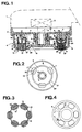
- Figure 1 shows a partial cross-sectional view of a hair removal device according to the invention
- Figure 2 shows a bottom view on a smaller scale of the head of the device
- Figure 3 shows on the same scale as in Figure 2 a bottom view of the lifting means of the device
- Figure 4 also shows on the same scale as in Figure 2 a bottom view of the cover of the device.
- the hair removal device shown in Figure 1 comprises, in a housing 1 (shown in broken lines) intended to be held in the hand, a motor unit 2 (shown in broken lines) whose output shaft 3 rotates a hair removal tool 4.
- the housing 1 has a head 5 traversed by the shaft 3 and comprising on its external face 6 three cams 7 extending in height axially and in length according to a determined sector.
- the head 5 is advantageously made of plastic and is mounted on the housing 1 by a removable fixing means, for example by screwing (not shown) the head 5 on the housing 1.
- the hair removal tool 4 has a plastic cover 8 which is rotated by the shaft 3 of the motor 2 by means of a mutual coupling device, for example by interlocking complementary hexagonal shapes.
- the cover 8 is mounted on the head 5 by elastic locking means, for example by means of elastic lugs 9 penetrating into a housing 10.
- the cover 8 has six openings 11.
- the hair removal tool 4 further comprises six tear-off means 12 arranged circumferentially and partially passing through the respective openings 11 of the cover 8.
- the tear-off means are thus integral in rotation with the cover.
- Each lifting means 12 comprises teeth 13 axially directed, arranged concentrically with the shaft 3 and integral with an operating member 14 of the teeth.
- the operating means 14 and the teeth 13 are advantageously made in a single piece of plastic material such as for example homopolymer polyacetal, sold under the name DELRIN (brand of the Dupont de Nemours company).
- Each operating member 14 has a foot in which a U-shaped groove 15 is formed, open in the direction of the cam 7 and of radial width less than that of the cam 7.
- the groove 15 has lateral walls 16 extending in an arc concentric with the tree and a bottom 17, carrying the teeth, which is thinned. Said bottom of the groove 15 thus constitutes a sort of connecting hinge between the teeth and the side walls.
- each tear-off means 12 can occupy practically two states, that is to say a tear-off state in which it is brought by pressing the cam 7 on the operating member 14 and for which the teeth 13 are brought together against each other to grip the bristles, that is to say a state of rest in which it is brought about by release of said operating member 14 which recovers its shape and for which the teeth 13 are separated.
- each wall 16 pivoting around a horizontal pivot 18 located in the bottom 17 at the junction of the wall 16 and the bottom 17 , and transmitting in particular its pivoting movement to the corresponding external tooth (13 ').
- Said pivot 18 is materially constituted by the connection between the thinned bottom and the assembly formed by the wall and the corresponding tooth.
- a foot 14 engages on a cam 7 which is inserted between the side walls 16 of said foot 14 and which, due to the more large radial width of the cam, separates said walls 16 from one another.
- This symmetrical support on the walls 16 causes the teeth 13 to come together against each other, by a pivoting effect of the two external teeth 13 'around the pivot 18.
- the bristles which are between the teeth 13 are then pinched.
- the rotational movement associated with the prolonged pinching then makes it possible to pluck the hairs.
- the deformation could be asymmetrical, the cam then pressing only on a single wall.
- the teeth 13 slightly protruding from the cover 8, perform a light massage of the skin to make hair removal more pleasant.
- the tear-off means 12 are carried by a ring 19 concentric with the shaft 3 and each groove 15 of a foot 14 is equipped with a guide rib 20 arranged at center of the groove 15, concentrically with the shaft 3 and the crown 19 is arranged in the extension of the ribs 20.
- the cams 7 are connected together by an annular skirt 21 extending axially, and have circumferentially a slot 22 whose bottom 23 is located at the same level as the free edge 24 of the skirt 21.
- the rib 20 comes, on the one hand, to be introduced into the slot 22 when the stripping means 12 occupy their stripping state and, on the other hand, opposite the free edge 24 of the skirt 21 when the tearing means 12 occupy their rest state.
- the crown 19 is supported on the internal face 25 of the cover 8 between the openings 11.
- the crown 19 is held between the cover 8 and the skirt 21 of the head 5, preventing any unwanted axial movement for good lifting efficiency.
- the head 5 being removable, the assembly produced by said head and the hair removal tool 4 can constitute an accessory which can be interchanged, for example, with a massage tool, for polishing the skin, etc. more, the head 5 and the hair removal tool 4 being entirely made of plastic, they are easy to clean because it can, for example, immerse the assembly in a disinfectant liquid such as alcohol.
Description
L'invention se rapporte aux appareils épilatoires électriques destinés à être tenu à la main.The invention relates to electric depilatory devices intended to be held in the hand.
L'invention se rapporte, plus particulièrement, à un appareil épilatoire comprenant, dans un boîtier destiné à être tenu à la main, un groupe moteur dont l'arbre de sortie entraîne en rotation un outil d'épilation. Un tel appareil est connu par EP-A-0 342 546.The invention relates, more particularly, to a hair removal device comprising, in a housing intended to be held in the hand, a motor unit whose output shaft rotates a hair removal tool. Such an apparatus is known from EP-A-0 342 546.
Dans les appareils épilatoires connus, l'outil d'arrachage est souvent constitué par un ressort tournant sur lui-même ou des lames métalliques rotatives. Ces appareils présentent l'inconvénient d'être assez douloureux et parfois de ne pas arracher correctement le poil mais de le casser à la surface de la peau.In known depilatory devices, the plucking tool often consists of a spring rotating on itself or of rotating metal blades. These devices have the disadvantage of being quite painful and sometimes not to pull the hair correctly but to break it on the surface of the skin.
L'invention a pour but de remédier à ces inconvénients et de réaliser notamment un appareil plus efficace, tout en étant agréable à utiliser.The object of the invention is to remedy these drawbacks and in particular to produce a more efficient device, while being pleasant to use.
Selon l'invention, le boîtier présente une tête traversée par l'arbre et comportant sur sa face externe au moins une came s'étendant axialement, tandis que l'outil d'épilation comporte, d'une part, un couvercle entraîné en rotation par l'arbre du moteur et présentant des ouvertures et, d'autre part, une pluralité de moyens d'arrachage agencés circonférentiellement et traversant partiellement les ouvertures respectives du couvercle, chaque moyen d'arrachage comportant des dents dirigées axialement, agencées concentriquement à l'arbre et solidaires d'un organe de manoeuvre déformable élastiquement, de manière que, lors de la rotation du couvercle, chaque moyen d'arrachage puisse occuper pratiquement deux états, soit un état d'arrachage en lequel il est amené par appui de la came sur l'organe de manoeuvre et pour lequel les dents sont rapprochées les unes contre les autres pour saisir les poils, soit un état de repos en lequel il est amené par libération dudit organe de manoeuvre qui retrouve sa forme et pour lequel les dents sont écartées.According to the invention, the housing has a head through which the shaft passes and comprising on its external face at least one cam extending axially, while the depilation tool comprises, on the one hand, a cover driven in rotation by the motor shaft and having openings and, on the other hand, a plurality of tearing means arranged circumferentially and partially passing through the respective openings of the cover, each tearing means having axially directed teeth, arranged concentrically with the shaft and integral with an elastically deformable operating member, so that, during the rotation of the cover, each tear-off means can occupy practically two states, namely a tear-off state in which it is brought by pressing the cam on the operating member and for which the teeth are brought together against each other to grasp the bristles, that is to say a state of rest in which it is brought about by release of said operating member which regains its shape and for which the teeth are separated .
Ainsi, les poils qui se trouvent entre les dents sont saisis au moment où les dents se resserrent, puis sont arrachés par l'effet combiné du coincement prolongé et du mouvement de rotation du couvercle. Quand les dents se desserrent les poils arrachés tombent d'eux-même. L'épilation est presque indolore puisque les poils sont saisis au plus près de la surface de la peau et donc de leur racine à la manière d'une pince. Le fait de multiplier le nombre de dents augmente d'autant le nombre de prises de poils, et donc l'efficacité de l'épilation. De plus, les moyens d'arrachage, dépassant légèrement du couvercle, réalisent, simultanément à l'arrachage des poils, un massage de la peau qui contribue à rendre l'épilation plus agréable.Thus, the hairs which are between the teeth are gripped at the moment when the teeth tighten, then are pulled out by the combined effect of the prolonged wedging and the rotational movement of the cover. When the teeth loosen the plucked hairs fall out on their own. Hair removal is almost painless since the hairs are gripped as close as possible to the surface of the skin and therefore to their roots in the manner of forceps. Multiplying the number of teeth increases the number of hair taken, and therefore the effectiveness of hair removal. In addition, the plucking means, protruding slightly from the cover, perform, simultaneously with plucking the hairs, a massage of the skin which contributes to making depilation more pleasant.
Les caractéristiques et avantages de l'invention ressortiront d'ailleurs de la description qui va suivre, à titre d'exemple, en référence au dessin annexé dans lequel :
la figure 1 représente une vue en coupe transversale partielle d'un appareil épilatoire selon l'invention ; la figure 2 représente une vue de dessous à plus petite échelle de la tête de l'appareil ; la figure 3 représente à la même échelle qu'à la figure 2 une vue de dessous des moyens d'arrachage de l'appareil ; la figure 4 représente également à la même échelle qu'à la figure 2 une vue de dessous du couvercle de l'appareil.The characteristics and advantages of the invention will become apparent from the description which follows, by way of example, with reference to the appended drawing in which:
Figure 1 shows a partial cross-sectional view of a hair removal device according to the invention; Figure 2 shows a bottom view on a smaller scale of the head of the device; Figure 3 shows on the same scale as in Figure 2 a bottom view of the lifting means of the device; Figure 4 also shows on the same scale as in Figure 2 a bottom view of the cover of the device.
L'appareil épilatoire représenté sur la figure 1 comprend, dans un boîtier 1 (représenté en traits interrompus) destiné à être tenu à la main, un groupe moteur 2 (représenté en traits interrompus) dont l'arbre de sortie 3 entraîne en rotation un outil d'épilation 4.The hair removal device shown in Figure 1 comprises, in a housing 1 (shown in broken lines) intended to be held in the hand, a motor unit 2 (shown in broken lines) whose output shaft 3 rotates a hair removal tool 4.
Le boîtier 1 présente une tête 5 traversée par l'arbre 3 et comportant sur sa face externe 6 trois cames 7 s'étendant en hauteur axialement et en longueur selon un secteur déterminé. La tête 5 est avantageusement réalisée en matière plastique et est montée sur le boîtier 1 par un moyen de fixation amovible, par exemple par vissage (non représenté) de la tête 5 sur le boîtier 1.The housing 1 has a
L'outil d'épilation 4 comporte un couvercle 8 en matière plastique qui est entraîné en rotation par l'arbre 3 du moteur 2 au moyen d'un dispositif d'accouplement mutuel, par exemple par emboîtement de formes hexagonales complémentaires. Le couvercle 8 est monté sur la tête 5 par des moyens élastiques de verrouillage, par exemple au moyen d'ergots élastiques 9 pénétrant dans un logement 10. Le couvercle 8 présente six ouvertures 11.The hair removal tool 4 has a
L'outil d'épilation 4 comporte, en outre, six moyens d'arrachage 12 agencés circonférentiellement et traversant partiellement les ouvertures respectives 11 du couvercle 8. Les moyens d'arrachage sont ainsi solidaires en rotation du couvercle. Chaque moyen d'arrachage 12 comporte des dents 13 dirigées axialement, agencées concentriquement à l'arbre 3 et solidaires d'un organe de manoeuvre 14 des dents.The hair removal tool 4 further comprises six tear-
Les moyens de manoeuvre 14 et les dents 13 sont avantageusement réalisés d'une seule pièce en matériau plastique tel que par exemple du polyacétal homopolymère, vendu sous le nom de DELRIN (marque de la Société Dupont de Nemours).The operating means 14 and the
Chaque organe de manoeuvre 14 comporte un pied dans lequel est ménagée une rainure 15 en forme de U, ouverte en direction de la came 7 et de largeur radiale inférieure à celle de la came 7. La rainure 15 comporte des parois latérales 16 s'étendant selon un arc de cercle concentrique à l'arbre et un fond 17, portant les dents, qui est aminci. Ledit fond de la rainure 15 constitue ainsi une sorte de charnière de liaison entre les dents et les parois latérales.Each
De cette manière, lors de la rotation du couvercle 8, chaque moyen d'arrachage 12 peut occuper pratiquement deux états, soit un état d'arrachage en lequel il est amené par appui de la came 7 sur l'organe de manoeuvre 14 et pour lequel les dents 13 sont rapprochées les unes contre les autres pour saisir les poils, soit un état de repos en lequel il est amené par libération dudit organe de manoeuvre 14 qui retrouve sa forme et pour lequel les dents 13 sont écartées.In this way, during the rotation of the
Comme on le comprendra, en position d'arrachage la came 7, vient appuyer latéralement sur les parois latérales 16, chaque paroi 16 pivotant autour d'un pivot horizontal 18 localisé dans le fond 17 à la jonction de la paroi 16 et du fond 17, et transmettant notamment son mouvement de pivotement à la dent extérieure correspondante (13'). Ledit pivot 18 est matériellement constitué par la liaison entre le fond aminci et l'ensemble formé par la paroi et la dent correspondante.As will be understood, in the tear-off position the
Ainsi, lors de la rotation du couvercle 8 qui est d'environ 160 tours/minute, un pied 14 vient s'engager sur une came 7 qui s'insère entre les parois latérales 16 dudit pied 14 et qui, du fait de la plus grande largueur radiale de la came, écarte lesdites parois 16 l'une de l'autre. Cet appui symétrique sur les parois 16 entraîne le rapprochement des dents 13 les unes contre les autres, par un effet de pivotement des deux dents externes 13' autour du pivot 18. Les poils qui se trouvent entre les dents 13 sont alors pincés. Le mouvement de rotation associé au pincement prolongé permet alors d'arracher les poils. Selon un autre mode de réalisation non représenté, la déformation pourrait être asymétrique, la came n'appuyant alors que sur une seule paroi.Thus, during the rotation of the
La rotation se poursuit et le pied 14 se trouve libéré de la came 7. Du fait de l'élasticité dudit pied 14, les parois latérales 16 retrouvent leur position initiale et les dents 13 s'écartent, relâchant ainsi les poils arrachés. La vitesse et le courant d'air entre les dents 13 facilite l'évacuation des poils.The rotation continues and the
En outre, les dents 13 dépassant légèrement du couvercle 8, réalisent un léger massage de la peau pour rendre l'épilation plus agréable.In addition, the
Comme on le voit mieux sur les figures 1 et 3, les moyens d'arrachage 12 sont portés par une couronne 19 concentrique à l'arbre 3 et chaque rainure 15 d'un pied 14 est équipée d'une nervure de guidage 20 agencée au centre de la rainure 15, concentriquement à l'arbre 3 et la couronne 19 est agencée dans le prolongement des nervures 20.As best seen in Figures 1 and 3, the tear-off means 12 are carried by a
Comme on le voit mieux sur les figures 1 et 2, les cames 7 sont reliées entre elles par une jupe annulaire 21 s'étendant axialement, et présentent circonférentiellement une fente 22 dont le fond 23 est situé au même niveau que le bord libre 24 de la jupe 21. De cette manière, la nervure 20 vient, d'une part, s'introduire dans la fente 22 lorsque les moyens d'arrachage 12 occupent leur état d'arrachage et, d'autre part, en regard du bord libre 24 de la jupe 21 lorsque les moyens d'arrachage 12 occupent leur état de repos.As best seen in Figures 1 and 2, the
Ainsi, grâce à la nervure 20 et à la fente 22, les pieds 14 sont toujours guidés de manière que les cames 7 soient exactement au centre desdits pieds 14. La déformation obtenue est donc parfaitement symétrique et provoque un serrage optimum des dents 13.Thus, by virtue of the rib 20 and the slot 22, the
Afin de garantir une hauteur constante de dépassement des dents 13 par rapport au couvercle 8, la couronne 19 s'appuie sur la face interne 25 du couvercle 8 entre les ouvertures 11. Ainsi la couronne 19 se trouve maintenue entre le couvercle 8 et la jupe 21 de la tête 5, empêchant tout mouvement axial indésirable pour une bonne efficacité d'arrachage.In order to guarantee a constant height of projection of the
La tête 5 étant démontable, l'ensemble réalisé par ladite tête et l'outil d'épilation 4 peut constituer un accessoire que l'on peut interchanger, par exemple, avec un outil de massage, de polissage de la peau ... De plus, la tête 5 et l'outil d'épilation 4 étant entièrement réalisés en matière plastique, ils sont facilement nettoyables car on peut, par exemple, plonger l'ensemble dans un liquide désinfectant tel que l'alcool.The
Claims (8)
- A depilating appliance comprising, in a housing (1) designed to be hand-held, a motor unit (2), the output shaft (3) of which rotationally drives a depilating tool (4),
characterised in that the housing (1) has a head (5) through which the shaft (3) passes and comprising on its outer face (6) at least one axially extending cam (7), whereas the depilating tool (4) comprises, firstly, a cover (8) adapted to be rotationally driven by the shaft (3) of the motor and having apertures (11) and, secondly, a plurality of extraction means (12) disposed circumferentially and partially passing through the respective apertures (11) of the cover (8), each extraction means (12) comprising axially directed teeth (13), disposed concentrically to the shaft (3) and integral with an elastically deformable control mechanism (14), so that, with the rotation of the cover (8), each extraction means (12) may in practice occupy two position, either an extraction position into which it is brought by the cam (7) bearing on the control mechanism (14) and for which the teeth (13) are brought closer together in order to grasp the hairs, or an off position into which it is brought by releasing said control mechanism (14) which reassume its shape and for which the teeth (13) are separated. - A depilating appliance according to Claim 1,
characterised in that the control mechanism (14) and the teeth (13) are made in a single piece and each control mechanism (14) comprises a foot in which a U-shaped groove (15), open in the direction of the cam (7) and having a radial width less than that of the cam (7), is provided, the groove (15) having lateral walls (16) which extend along an arc of a circle concentric with the shaft and the base (17) bearing the teeth of which is made thinner, so that, when the cam (7), in the extraction position, comes to rest laterally on at least one lateral wall (16), the said wall (16) pivots around a horizontal pivot (18) situated in the base (17) and transmits in particular its pivoting movement to the corresponding outer tooth (13'). - A depilating appliance according to Claim 1 or 2,
characterised in that the extraction means (12) are borne by a crown (19) concentric to the shaft (3). - A depilating appliance according to Claim 3,
characterised in that each groove (15) is equipped with a guide rib (20) disposed in the centre of the groove (15), concentrically to the shaft (3) and the crown (19) is disposed in the extension of the ribs (20), whereas the cams (7) are inter-connected by an axially extending annular skirt (21) and circumferentially have an aperture (22), the base (23) of which is situated at the same level as the free edge (24) of the skirt (21), so that the rib (20) comes, firstly, to be introduced into the aperture (22) when the extraction means (12) occupy their extraction position and, secondly, opposite the free edge (24) of the skirt (21) when the extraction means (12) occupy their off position. - A depilating appliance according to Claim 3 or 4,
characterised in that the crown (19) rests on the inner face (25) of the cover (8) between the apertures (11). - A depilating appliance according to any one of the preceding Claims,
characterised in that there are three cams (7), whereas the there are six extraction means (12) and corresponding apertures (11). - A depilating appliance according to any one of the preceding Claims,
characterised in that the cover (8) is mounted on the head (5) by elastic locking means (9, 10) and is rotationally driven by the shaft (3) of the motor (2) by means of a mutual coupling device, whereas the head (5) is itself mounted on the housing (1) by a removable fixing means. - A depilating appliance according to any one of the preceding Claims,
characterised in that the control mechanisms (14) and the teeth (13) are made from plastic material such as homopolymer polyacetal for example.
Applications Claiming Priority (2)
| Application Number | Priority Date | Filing Date | Title |
|---|---|---|---|
| FR9001760 | 1990-02-14 | ||
| FR9001760A FR2658050B1 (en) | 1990-02-14 | 1990-02-14 | EPILATORY APPARATUS. |
Publications (3)
| Publication Number | Publication Date |
|---|---|
| EP0442419A2 EP0442419A2 (en) | 1991-08-21 |
| EP0442419A3 EP0442419A3 (en) | 1993-01-20 |
| EP0442419B1 true EP0442419B1 (en) | 1995-04-12 |
Family
ID=9393714
Family Applications (1)
| Application Number | Title | Priority Date | Filing Date |
|---|---|---|---|
| EP19910101880 Expired - Lifetime EP0442419B1 (en) | 1990-02-14 | 1991-02-11 | Epilating apparatus |
Country Status (4)
| Country | Link |
|---|---|
| EP (1) | EP0442419B1 (en) |
| DE (1) | DE69108756T2 (en) |
| ES (1) | ES2073049T3 (en) |
| FR (1) | FR2658050B1 (en) |
Cited By (1)
| Publication number | Priority date | Publication date | Assignee | Title |
|---|---|---|---|---|
| US6293953B1 (en) | 1995-06-14 | 2001-09-25 | Braun Aktiengesellschaft | Appliance for plucking hairs out of human skin |
Families Citing this family (10)
| Publication number | Priority date | Publication date | Assignee | Title |
|---|---|---|---|---|
| US5100413A (en) * | 1991-03-05 | 1992-03-31 | Moshe Dolev | Rotary head multi-tweezer hair removal device |
| DE4120014C1 (en) * | 1991-06-18 | 1992-06-17 | Braun Ag, 6000 Frankfurt, De | |
| JPH07500984A (en) * | 1991-11-20 | 1995-02-02 | パイヤー エレクトロプロドゥクテ ゲゼルシャフト ミット ベシュレンクテル ハフツング | hair removal device |
| US5217469A (en) * | 1992-01-27 | 1993-06-08 | Moshe Dolev | Rotary head spring-loaded tweezer hair removal device |
| US5196021A (en) * | 1992-02-25 | 1993-03-23 | Perfect Lady Ltd. | Depilatory device |
| WO1994019984A1 (en) * | 1993-03-09 | 1994-09-15 | Payer Elektroprodukte Gesellschaft M.B.H. | Depilatory appliance |
| ATE218824T1 (en) * | 1996-08-06 | 2002-06-15 | Braun Gmbh | ROTARY CYLINDER FOR AN EPILATION DEVICE |
| FR2833470B1 (en) * | 2001-12-17 | 2004-02-27 | Seb Sa | HAIR REMOVAL EQUIPMENT WITH EXFOLIATING HEAD |
| JP4120247B2 (en) * | 2002-03-26 | 2008-07-16 | 松下電工株式会社 | Beauty equipment |
| ES2643313T3 (en) * | 2008-05-27 | 2017-11-22 | Braun Gmbh | Device for hair removal |
Family Cites Families (1)
| Publication number | Priority date | Publication date | Assignee | Title |
|---|---|---|---|---|
| IL86447A (en) * | 1988-05-19 | 1994-04-12 | Yahav Shimon | Electrically powered depilatory device |
-
1990
- 1990-02-14 FR FR9001760A patent/FR2658050B1/en not_active Expired - Fee Related
-
1991
- 1991-02-11 DE DE1991608756 patent/DE69108756T2/en not_active Expired - Fee Related
- 1991-02-11 ES ES91101880T patent/ES2073049T3/en not_active Expired - Lifetime
- 1991-02-11 EP EP19910101880 patent/EP0442419B1/en not_active Expired - Lifetime
Cited By (5)
| Publication number | Priority date | Publication date | Assignee | Title |
|---|---|---|---|---|
| US6293953B1 (en) | 1995-06-14 | 2001-09-25 | Braun Aktiengesellschaft | Appliance for plucking hairs out of human skin |
| US6730099B1 (en) | 1995-06-14 | 2004-05-04 | Braun Gmbh | Appliance for plucking hairs out of human skin |
| US7147645B2 (en) | 1995-06-14 | 2006-12-12 | The Gillette Company | Appliance for the epilation of the human skin |
| US7195635B2 (en) | 1995-06-14 | 2007-03-27 | The Gillette Company | Appliance for the epilation of the human skin |
| US7211090B2 (en) | 1995-06-14 | 2007-05-01 | The Gillette Company | Appliance for plucking hairs out of human skin |
Also Published As
| Publication number | Publication date |
|---|---|
| EP0442419A3 (en) | 1993-01-20 |
| DE69108756D1 (en) | 1995-05-18 |
| FR2658050B1 (en) | 1993-12-03 |
| EP0442419A2 (en) | 1991-08-21 |
| FR2658050A1 (en) | 1991-08-16 |
| ES2073049T3 (en) | 1995-08-01 |
| DE69108756T2 (en) | 1995-09-07 |
Similar Documents
| Publication | Publication Date | Title |
|---|---|---|
| EP0442419B1 (en) | Epilating apparatus | |
| EP0147285B1 (en) | Epilation apparatus | |
| EP1772087B1 (en) | Mixing rod and domestic mixing device of the immersing type with such a mixing rod | |
| EP0364321B1 (en) | Depilating apparatus | |
| FR2796831A1 (en) | Attachment for an electric toothbrush allows exchange of brush heads | |
| FR2520281A1 (en) | ELECTRIC RAZOR | |
| FR2462974A1 (en) | SHAVING BLOCK FOR ELECTRIC RAZOR WITH ROTATING HEAD | |
| EP1702541B1 (en) | Fruit squeezer having an articulated arm with a pressing memeber | |
| FR2582203A1 (en) | WASHING BRUSH WITH WATER SUPPLY AND ROTATING BRISTLES, PARTICULARLY FOR MOTOR VEHICLES | |
| EP0467733B1 (en) | Hair removal apparatus with brush | |
| WO1998042284A1 (en) | Ear-spoon | |
| EP0734213B1 (en) | Brush containing comb | |
| US7784190B2 (en) | Can opener | |
| FR2471840A1 (en) | DRY RAZOR WITH PREPARING KNIVES | |
| FR2754321A1 (en) | DRIVE HEAD FORMING TORQUE LIMITER FOR AGITATOR PAINT CONTAINERS | |
| EP1652447A1 (en) | Hair removal device comprising a skin treatment accessory | |
| FR2658399A1 (en) | HAIR REMOVAL DEVICE. | |
| FR2792162A3 (en) | Brush cutter head has pivoted plastic blades held in place by springloaded pins for easy blade replacement | |
| EP1300095B1 (en) | Depilatory appliance comprising pain-killing means | |
| FR2560748A1 (en) | Device for automatic unclogging of a cylindrical rotary grille, particularly of a fruit-crushing and stalk-removing machine | |
| FR2651424A1 (en) | Device for peeling by hand | |
| FR2697416A1 (en) | Hair removal device to remove body hair. | |
| FR2656993A2 (en) | Hair-removing apparatus | |
| EP3673763A1 (en) | Hair-removal head for hair removal device having a single row of clamps | |
| FR2767021A1 (en) | Hand tool for gathering peduncular vegetation, |
Legal Events
| Date | Code | Title | Description |
|---|---|---|---|
| PUAI | Public reference made under article 153(3) epc to a published international application that has entered the european phase |
Free format text: ORIGINAL CODE: 0009012 |
|
| AK | Designated contracting states |
Kind code of ref document: A2 Designated state(s): DE ES GB |
|
| PUAL | Search report despatched |
Free format text: ORIGINAL CODE: 0009013 |
|
| AK | Designated contracting states |
Kind code of ref document: A3 Designated state(s): DE ES GB |
|
| 17P | Request for examination filed |
Effective date: 19930315 |
|
| 17Q | First examination report despatched |
Effective date: 19940713 |
|
| GRAA | (expected) grant |
Free format text: ORIGINAL CODE: 0009210 |
|
| AK | Designated contracting states |
Kind code of ref document: B1 Designated state(s): DE ES GB |
|
| REF | Corresponds to: |
Ref document number: 69108756 Country of ref document: DE Date of ref document: 19950518 |
|
| GBT | Gb: translation of ep patent filed (gb section 77(6)(a)/1977) |
Effective date: 19950427 |
|
| REG | Reference to a national code |
Ref country code: ES Ref legal event code: FG2A Ref document number: 2073049 Country of ref document: ES Kind code of ref document: T3 |
|
| PLBE | No opposition filed within time limit |
Free format text: ORIGINAL CODE: 0009261 |
|
| STAA | Information on the status of an ep patent application or granted ep patent |
Free format text: STATUS: NO OPPOSITION FILED WITHIN TIME LIMIT |
|
| 26N | No opposition filed | ||
| PGFP | Annual fee paid to national office [announced via postgrant information from national office to epo] |
Ref country code: GB Payment date: 19990209 Year of fee payment: 9 |
|
| PGFP | Annual fee paid to national office [announced via postgrant information from national office to epo] |
Ref country code: ES Payment date: 19990224 Year of fee payment: 9 |
|
| PGFP | Annual fee paid to national office [announced via postgrant information from national office to epo] |
Ref country code: DE Payment date: 19990323 Year of fee payment: 9 |
|
| PG25 | Lapsed in a contracting state [announced via postgrant information from national office to epo] |
Ref country code: GB Free format text: LAPSE BECAUSE OF NON-PAYMENT OF DUE FEES Effective date: 20000211 |
|
| PG25 | Lapsed in a contracting state [announced via postgrant information from national office to epo] |
Ref country code: ES Free format text: THE PATENT HAS BEEN ANNULLED BY A DECISION OF A NATIONAL AUTHORITY Effective date: 20000212 |
|
| GBPC | Gb: european patent ceased through non-payment of renewal fee |
Effective date: 20000211 |
|
| PG25 | Lapsed in a contracting state [announced via postgrant information from national office to epo] |
Ref country code: DE Free format text: LAPSE BECAUSE OF NON-PAYMENT OF DUE FEES Effective date: 20001201 |
|
| REG | Reference to a national code |
Ref country code: ES Ref legal event code: FD2A Effective date: 20010910 |