EP0442553A1 - Optical amplifier having a single-mode curved active fibre - Google Patents
Optical amplifier having a single-mode curved active fibre Download PDFInfo
- Publication number
- EP0442553A1 EP0442553A1 EP91200156A EP91200156A EP0442553A1 EP 0442553 A1 EP0442553 A1 EP 0442553A1 EP 91200156 A EP91200156 A EP 91200156A EP 91200156 A EP91200156 A EP 91200156A EP 0442553 A1 EP0442553 A1 EP 0442553A1
- Authority
- EP
- European Patent Office
- Prior art keywords
- fiber
- wavelength
- pumping
- active
- optical
- Prior art date
- Legal status (The legal status is an assumption and is not a legal conclusion. Google has not performed a legal analysis and makes no representation as to the accuracy of the status listed.)
- Granted
Links
Images

Classifications
-
- G—PHYSICS
- G02—OPTICS
- G02B—OPTICAL ELEMENTS, SYSTEMS OR APPARATUS
- G02B6/00—Light guides; Structural details of arrangements comprising light guides and other optical elements, e.g. couplings
-
- H—ELECTRICITY
- H04—ELECTRIC COMMUNICATION TECHNIQUE
- H04B—TRANSMISSION
- H04B10/00—Transmission systems employing electromagnetic waves other than radio-waves, e.g. infrared, visible or ultraviolet light, or employing corpuscular radiation, e.g. quantum communication
- H04B10/29—Repeaters
- H04B10/291—Repeaters in which processing or amplification is carried out without conversion of the main signal from optical form
-
- H—ELECTRICITY
- H01—ELECTRIC ELEMENTS
- H01S—DEVICES USING THE PROCESS OF LIGHT AMPLIFICATION BY STIMULATED EMISSION OF RADIATION [LASER] TO AMPLIFY OR GENERATE LIGHT; DEVICES USING STIMULATED EMISSION OF ELECTROMAGNETIC RADIATION IN WAVE RANGES OTHER THAN OPTICAL
- H01S3/00—Lasers, i.e. devices using stimulated emission of electromagnetic radiation in the infrared, visible or ultraviolet wave range
- H01S3/05—Construction or shape of optical resonators; Accommodation of active medium therein; Shape of active medium
- H01S3/06—Construction or shape of active medium
- H01S3/063—Waveguide lasers, i.e. whereby the dimensions of the waveguide are of the order of the light wavelength
- H01S3/067—Fibre lasers
- H01S3/06708—Constructional details of the fibre, e.g. compositions, cross-section, shape or tapering
-
- H—ELECTRICITY
- H04—ELECTRIC COMMUNICATION TECHNIQUE
- H04B—TRANSMISSION
- H04B10/00—Transmission systems employing electromagnetic waves other than radio-waves, e.g. infrared, visible or ultraviolet light, or employing corpuscular radiation, e.g. quantum communication
- H04B10/29—Repeaters
- H04B10/291—Repeaters in which processing or amplification is carried out without conversion of the main signal from optical form
- H04B10/2912—Repeaters in which processing or amplification is carried out without conversion of the main signal from optical form characterised by the medium used for amplification or processing
-
- H—ELECTRICITY
- H01—ELECTRIC ELEMENTS
- H01S—DEVICES USING THE PROCESS OF LIGHT AMPLIFICATION BY STIMULATED EMISSION OF RADIATION [LASER] TO AMPLIFY OR GENERATE LIGHT; DEVICES USING STIMULATED EMISSION OF ELECTROMAGNETIC RADIATION IN WAVE RANGES OTHER THAN OPTICAL
- H01S3/00—Lasers, i.e. devices using stimulated emission of electromagnetic radiation in the infrared, visible or ultraviolet wave range
- H01S3/05—Construction or shape of optical resonators; Accommodation of active medium therein; Shape of active medium
- H01S3/08—Construction or shape of optical resonators or components thereof
- H01S3/08018—Mode suppression
- H01S3/0804—Transverse or lateral modes
- H01S3/08045—Single-mode emission
-
- H—ELECTRICITY
- H01—ELECTRIC ELEMENTS
- H01S—DEVICES USING THE PROCESS OF LIGHT AMPLIFICATION BY STIMULATED EMISSION OF RADIATION [LASER] TO AMPLIFY OR GENERATE LIGHT; DEVICES USING STIMULATED EMISSION OF ELECTROMAGNETIC RADIATION IN WAVE RANGES OTHER THAN OPTICAL
- H01S3/00—Lasers, i.e. devices using stimulated emission of electromagnetic radiation in the infrared, visible or ultraviolet wave range
- H01S3/09—Processes or apparatus for excitation, e.g. pumping
- H01S3/091—Processes or apparatus for excitation, e.g. pumping using optical pumping
- H01S3/094—Processes or apparatus for excitation, e.g. pumping using optical pumping by coherent light
- H01S3/094065—Single-mode pumping
Definitions
- the present invention relates to an optical amplifier, in particular for telecommunications lines, using an active fiber single-moded at the transmission wavelength only.
- optical fibers having a doped core obtained by the use of particular substances such as rare earth ions have stimulated-emission features adapted for use as laser sources and optical amplifiers.
- these fibers can be supplied with a light source of a particular wavelength, referred to as pumping wavelength, which is capable of bringing the dopant atoms to an excited energetic state, or pumping band, from which the atoms spontaneously decay within a very short period of time into a laser emission state, in which state they remain for a relatively long period of time.
- pumping wavelength a light source of a particular wavelength, referred to as pumping wavelength
- a fiber having a high number of atoms at the excited state in the laser emission level is passed through by a light signal having a wavelength corresponding to that laser emission state, the signal causes the transition of the excited atoms to a lower level, the light emission having the same wavelength as the signal; therefore a fiber of the above kind can be used in order to achieve an amplification of the signal and in particular, for example, to achieve optical line amplifiers adapted to bring an attenuated-transmission optical signal back to a high level after a long travel through a fiber in a telecommunications line.
- Optical amplifiers of the above kind are for example known from the Italian Patent Application No. 22120 A/89 in the name of the same applicant, filed on October 24 th , 1989, in which the active fiber is provided to be of the single-mode type both at the transmission wavelength and at the pumping wavelength.
- the fluorescent dopant responsible for the transmission signal amplification, is concentrated in the fiber core and the fiber in known amplifiers is such designed that the pumping power be confined in said area too, so that it can be entirely used to excite the fluorescent dopant in the laser emission level; since however part of the transmission signal power is transmitted to the fiber outside the area in which the fluorescent dopant and pumping power are present, it results that only part of said signal is available in the fiber area in which it can be amplified.
- the above phenomenon brings about a limitation in the amplification efficiency of the amplifier, meant as the gain of the transmission signal per pumping power unit.
- the present invention aims at providing an amplifier in which the transmission signal power and the pumping power have a substantially similar distribution in the active fiber section and are also concentrated in the fiber area in which the fluorescent dopant is present.
- an optical amplifier in particular for optical-fiber telecommunications lines insertable in series in the optical fiber of a line, comprising at least a luminous pumping source, a dichroic coupler having two inputs connected to the optical line fiber carrying a transmission signal and to the luminous pumping source respectively, and an output connected to one end of an active fiber containing a fluorescent dopant in the respective optical core, with emission in the wavelength range of the transmission signal and to be pumped at the wavelength of the pumping source, characterized in that the active optical fiber is a fiber that in a substantially rectilinear configuration permits the luminous single-mode propagation at the transmission wavelength and the luminous multi-mode propagation at the pumping wavelength and is disposed in a curved configuration at least over 7O% of its overall length, with a bending radius corresponding to the propagation in the fiber of the fundamental mode alone at the pumping wavelength.
- the bending radius of the curved active fiber is in the range of 20 to 140 mm and preferably the bending radius of the active fiber ranges between 35 and 100 mm.
- the transmission wavelength is between 1520 and 1570 nm and the pumping wavelength is 980 nm ( ⁇ 10 nm) and the fluorescent dopant in the active fiber is erbium.
- the active fiber has at least a curved portion having a bending radius corresponding to the propagation in the fiber itself of the fundamental mode alone at the pumping wavelength, which portion is contiguous to non-curved fiber portions, the length of the curved portion or the sum of the curved portion lengths being higher than 70% of the overall length of the active fiber.
- the active fiber exhibits a single continuous curved portion with a bending radius corresponding to the propagation in the fiber itself of the fundamental mode alone at the pumping wavelength, portions of non-curved fiber being present at either or both ends of the active fiber.
- the active fiber is curved with a bending radius corresponding to the propagation in the fiber itself of the fundamental mode alone at the pumping wavelength over the whole length thereof, apart from the substantially devoid-of-curve end portions, having each a length lower than 400 mm; preferably the length of the substantially devoid-of-curve end portions is lower than 200 mm.
- Fig. 1 denotes an optical telecommunications fiber to which a transmission signal of a wavelength ⁇ s , generated by a signal laser emitter 2 is sent; the signal, being attenuated after a certain line length, is sent to an optical amplifier 3, substantially consisting of a dichroic coupler 4 where it is joined on a single outgoing fiber 5, to a pumping signal of wavelength ⁇ p , generated by a pumping laser emitter 6; an active fiber 7 connected to the fiber 5 issuing from the coupler, constitutes the signal amplifying element which is then introduced again into the line fiber 1 and goes on towards its destination.
- a silica-based optical fiber is used, which is doped with a fluorescent material adapted to generate a light emission which is stimulated in the presence of a light signal that is thus amplified thereby.
- Er2O3 which can have stimulated transitions, also referred to as "laser” transitions, at wavelengths that are convenient for the remote transmission of telecommunications signals.
- the transition from band 8 to level 9 is associated with a thermal-type emission, which is dispersed outside the fiber (phonon radiation)
- the transition from level 9 to the base level 10 generates a light emission of a wavelength corresponding to the energetic value of the laser emission level 9; if a fiber containing a high amount of ions at the laser emission level is passed through by a signal of a wavelength corresponding to such an emission level, the signal causes the stimulated transition of the concerned ions from the emission state to the base state before the spontaneous decay thereof, with a cascade phenomenon producing the emission of a greatly amplified transmission signal at the outlet of the active fiber.
- Diagrammatically shown in fig. 4 is the end of a fiber seen in axial section and denoted by 11; a core 12 and a cladding 13 are defined for such a fiber and they are identified by different refractive indices.
- the dopant that is Er3+, is present within the core 12.
- the active fiber 7 in the amplifier be of the single-mode type both at the transmission wavelength and the pumping wavelength, as disclosed in the Italian patent application No. 22120 A/89 in the name of the same applicant.
- the active fiber is such sized that the fiber cut-off wavelength ⁇ c1 , also referred to as " ⁇ cut-off " above which the propagation of the fundamental mode alone occurs in the fiber, is both lower than the wavelength of the transmission signal ⁇ s , and lower than the wavelength of the pumping radiation ⁇ p .
- the important measurements for the purpose of selecting the cut-off wavelength of the fiber are substantially the numerical aperture NA and core diameter thereof.
- NA (n12 - n22) 1/2 where n1 is the refractive index of the fiber core and n2 is the refractive index of the fiber cladding.
- the desired refractive indices of the fiber core and cladding can be achieved by selecting the concentration in the core and cladding themselves of the primary dopant, or index variator dopant, introduced into the preform from which the fiber is obtained through well-known techniques.
- the dopants used for the purpose usually consist of GeO2 or Al2O3.
- a light radiation having a wavelength for which there is a single-mode propagation in the fiber, that is higher than the fiber cut-off wavelength exhibits a radial distribution of the light intensity of the type shown in Fig. 4 by curves P and S the development of which is substantially of the Gauss type, with a maximum intensity I max along the fiber axis and decreasing values as far as zero towards the fiber periphery.
- a mode diameter ⁇ m is defined as the diameter at which there is a light intensity I( ⁇ m ) in the fiber: where I max is the maximum light intensity in the fiber, based on specifications CCITT G.652 (Consultative Committee International Telegram and Telephone).
- the transmission signal should have a radial-distribution intensity in the fiber similar to that of the pumping signal, for the purpose of being transmitted to the fiber region in which most of the luminous pumping power is present, so that it can be efficiently amplified.
- the mode diameters of the pumping signal and transmission signal should be as similar as possible.
- the mode diameter ⁇ s at the transmission wavelength ⁇ s is remarkably greater than the mode diameter ⁇ p at the pumping wavelength ⁇ p , with the intensity curve P, and substantially corresponding to the core 12 diameter; the above means that an important part of the light signal does not propagate into the area of the active fiber to which the pumping energy is supplied and in which the dopant is present.
- the mode diameter which for wavelength values close to the cut-off wavelength ⁇ c of the fiber is substantially constant and not very different from the core diameter of the fiber itself, for greater ⁇ values greatly increases, as shown in Fig. 7: therefore, in order to ensure that the fiber be single-mode at the pumping wavelength ⁇ p , for example in the case of amplifiers having an erbium-doped active fiber, at 980 nm ( ⁇ 10%), a fiber having a cut-off wavelength ⁇ c lower than 980 nm must be used and therefore a very high mode diameter at the transmission wavelength ⁇ s is achieved, which is by far greater than the mode diameter at the pumping wavelength ⁇ p , so that most of the transmission signal does not propagate into the fiber area in which it can be amplified.
- the active fiber has a rectilinear or substantially rectilinear configuration, where the term "substantially rectilinear configuration" means that the fiber is not submitted to geometrical deformations capable of greatly modifying the optical behaviour thereof; for said reason, in accordance with the specifications (CCITT, Instruction G.652), it is provided to evaluate the theoretical cut-off wavelength based on the profile of the refractive index in the fiber, and cut-off wavelengths in operating conditions.
- said specifications take into account the possibility of measuring a cut-off wavelength for a wired fiber, the measurement being carried out on a single fiber ring of a radius of 140 mm; the detected variation in the cut-off wavelength in these conditions as compared with the theoretical value is, on the other hand, rather small, a difference lower than about 5% with respect to the theoretical cut-off wavelength being expected.
- the active fiber of the amplifier is selected of the single-mode type at the transmission wavelength ⁇ s alone, that is having a value of cut-off wavelength ⁇ c2 lower than ⁇ s , but substantially higher than ⁇ p , as shown in Fig. 3.
- the mode diameter at the transmission wavelength particularly in the range between 1520 and 1570 nm, adapted for the use of amplifiers having an erbium-doped active fiber, being the transmission wavelength close to the cut-off wavelength, appears to be sufficiently small, substantially close to the diameter of the fiber core;
- the fundamental mode of the pumping signal in turn, has a diameter close to that of the fiber core and therefore the transmission signal power is maintained substantially confined within the fiber area in which the pumping signal and active dopant are present.
- the active fiber is disposed in a curved configuration over the whole length thereof, in the form of coils constituting the amplifier, as shown in Figs. 5 and 6, for example wound around a cylindrical support or the like: the fiber bending is selected in accordance with the present invention with a radius R c substantially lower than 140 mm, such as to permit the propagation of the fundamental mode alone within the fiber even for wavelengths lower than the above mentioned wavelength ⁇ c2 and in particular even for the pumping wavelength ⁇ p .
- the fiber bending in fact causes the same to transmit the fundamental mode alone for wavelengths that are increasingly smaller as the bending imparted to the fiber becomes more marked, that is as R c becomes smaller; therefore it is possible to define a bending radius R p under which, for a given wavelength and in particular for the pumping wavelength, the only propagation of the fundamental mode within the fiber is possible.
- the bending radius R c adopted for the active fiber is to be therefore lower than or equal to the above radius R p ; practically, since the bending can be caused by a mechanical weakening of the fiber structure, making it liable to breakages or crackings, preferably a bending radius equal to R p or close thereto is used.
- a fiber of shorter length can be used to achieve the desired amplification, as shown in Fig. 8, in which one can see that a gain G O can be reached with an active fiber of length L1, using a fiber of a cut-off length ⁇ c2 > 980 nm, greatly lower than the length L2 necessary to achieve the same gain with a fiber having a cut-off wavelength ⁇ c1 ⁇ 980 nm.
- the transport fiber 5 of the transmission signals coupled to the pumping signal is of the single-mode type at both wavelengths; this fiber has therefore a mode diameter at the transmission wavelength ⁇ s higher than the mode diameter in the active fiber in accordance with the invention; the welding between fibers 5 and 11 exhibits an attenuation at the transmission wavelength, due to such a diameter difference.
- a further light attenuation occurs in the welding between the active fiber and the line fiber 1; in fact although the commercially available fibers used as line fibers are of the single-mode type at the transmission wavelength alone, in said range between 1520 and 1570 nm, they have a rather high mode diameter, for the purpose of achieving easy joinings and the like, equal to or greater than the mode diameter of the coupler fiber 5.
- the minimum bending radius R c of the active fiber of appropriate use is higher than about 20 mm and under this radius the mechanical strength of the curved fiber becomes critical and in addition the welding losses at the junctions take important values, due to the great difference between the mode diameters of the active fiber and line fiber or the fiber coming out of the coupler, whereas bending radii higher than 140 mm are of little utility for achieving an important shifting of the cut-off wavelength; preferably R c > 35 mm and more preferably 50mm ⁇ R c ⁇ 100mm.
- the mode diameter at the wavelength of the transmission signal is higher than 6 ⁇ m.
- the active fiber qualities in the amplifier in accordance with the invention it is the overall length of the active fiber that should preferably be curved to the provided bending radius, that is the active fiber must be disposed in a curved configuration, for example wound to form coils on the respective support, as diagrammatically shown in Fig. 5, immediately downstream of the joining by welding 15 to the coupler fiber 5.
- the length L r of the rectilinear or substantially rectilinear active fiber portion 16, that is having a bending radius greater than R c as defined above immediately downstream of the coupler is lower than 400 mm and more preferably L r ⁇ 200 mm; such a substantially rectilinear fiber length can also be accepted at the opposite end of the active fiber, close to its joining to the line fiber, without the amplification efficiency being greatly impaired.
- the bent fiber portion constitutes the middle portion of the active fiber, whereas the leading and trailing fiber portions, contiguous to the end weldings of the fiber itself, can also have a rectilinear extension; however, due to particular requirements, the active fiber may also have several bent portions alternated with substantially rectilinear portions.
- the fiber-using amplifier had the following features:
- the fiber has been used in the amplifier under substantially rectilinear conditions, in the sense previously shown, so as to induce important variations in the cut-off wavelength thereof.
- the amplifier had the following features:
- the amplifier in accordance with the invention has been capable of supplying the same amplification gain as the comparative amplifier using a substantially rectilinear fiber, although a portion of active fiber of shorter length and lower pumping power has been used, thereby showing a remarkably greater efficiency.
- the support structure for the coiled fiber turns can be of any kind, also depending upon the structural features of the amplifier envelope, and it is not therefore described in detail.
Abstract
Description
- The present invention relates to an optical amplifier, in particular for telecommunications lines, using an active fiber single-moded at the transmission wavelength only.
- It is known that optical fibers having a doped core obtained by the use of particular substances such as rare earth ions, have stimulated-emission features adapted for use as laser sources and optical amplifiers.
- In fact these fibers can be supplied with a light source of a particular wavelength, referred to as pumping wavelength, which is capable of bringing the dopant atoms to an excited energetic state, or pumping band, from which the atoms spontaneously decay within a very short period of time into a laser emission state, in which state they remain for a relatively long period of time.
- When a fiber having a high number of atoms at the excited state in the laser emission level is passed through by a light signal having a wavelength corresponding to that laser emission state, the signal causes the transition of the excited atoms to a lower level, the light emission having the same wavelength as the signal; therefore a fiber of the above kind can be used in order to achieve an amplification of the signal and in particular, for example, to achieve optical line amplifiers adapted to bring an attenuated-transmission optical signal back to a high level after a long travel through a fiber in a telecommunications line.
- Optical amplifiers of the above kind are for example known from the Italian Patent Application No. 22120 A/89 in the name of the same applicant, filed on October 24th, 1989, in which the active fiber is provided to be of the single-mode type both at the transmission wavelength and at the pumping wavelength.
- These fibers however, which are single-moded both at the transmission wavelength and pumping wavelength, have a different distribution of the luminous power in the fiber section and in particular the luminous power of the transmission signal is distributed over a greater area of the fiber section than the area in which the pumping power is present.
- The fluorescent dopant, responsible for the transmission signal amplification, is concentrated in the fiber core and the fiber in known amplifiers is such designed that the pumping power be confined in said area too, so that it can be entirely used to excite the fluorescent dopant in the laser emission level; since however part of the transmission signal power is transmitted to the fiber outside the area in which the fluorescent dopant and pumping power are present, it results that only part of said signal is available in the fiber area in which it can be amplified.
- The above phenomenon brings about a limitation in the amplification efficiency of the amplifier, meant as the gain of the transmission signal per pumping power unit.
- Consequently the problem arises of increasing said efficiency with respect to known amplifiers.
- The present invention aims at providing an amplifier in which the transmission signal power and the pumping power have a substantially similar distribution in the active fiber section and are also concentrated in the fiber area in which the fluorescent dopant is present.
- It is an object of the present invention to provide an optical amplifier, in particular for optical-fiber telecommunications lines insertable in series in the optical fiber of a line, comprising at least a luminous pumping source, a dichroic coupler having two inputs connected to the optical line fiber carrying a transmission signal and to the luminous pumping source respectively, and an output connected to one end of an active fiber containing a fluorescent dopant in the respective optical core, with emission in the wavelength range of the transmission signal and to be pumped at the wavelength of the pumping source, characterized in that the active optical fiber is a fiber that in a substantially rectilinear configuration permits the luminous single-mode propagation at the transmission wavelength and the luminous multi-mode propagation at the pumping wavelength and is disposed in a curved configuration at least over 7O% of its overall length, with a bending radius corresponding to the propagation in the fiber of the fundamental mode alone at the pumping wavelength.
- The bending radius of the curved active fiber is in the range of 20 to 140 mm and preferably the bending radius of the active fiber ranges between 35 and 100 mm.
- In a preferred embodiment the transmission wavelength is between 1520 and 1570 nm and the pumping wavelength is 980 nm (± 10 nm) and the fluorescent dopant in the active fiber is erbium.
- In particular the active fiber has at least a curved portion having a bending radius corresponding to the propagation in the fiber itself of the fundamental mode alone at the pumping wavelength, which portion is contiguous to non-curved fiber portions, the length of the curved portion or the sum of the curved portion lengths being higher than 70% of the overall length of the active fiber.
- Preferably the active fiber exhibits a single continuous curved portion with a bending radius corresponding to the propagation in the fiber itself of the fundamental mode alone at the pumping wavelength, portions of non-curved fiber being present at either or both ends of the active fiber.
- In a particularly preferred embodiment of an optical amplifier in accordance with the invention the active fiber is curved with a bending radius corresponding to the propagation in the fiber itself of the fundamental mode alone at the pumping wavelength over the whole length thereof, apart from the substantially devoid-of-curve end portions, having each a length lower than 400 mm; preferably the length of the substantially devoid-of-curve end portions is lower than 200 mm.
- Further details will be drawn from the following description of the invention, with reference to the accompanying drawings, in which:
- Fig. 1 is a diagram showing an optical amplifier using an active fiber;
- Fig. 2 is a diagram showing the energetic transitions of a fiber of the type to be used for an amplifier according to the diagram of Fig. 1, which transitions are adapted to generate a stimulated (laser) emission;
- Fig. 3 is a diagram showing the arrangements relating to the pumping, transmission and cut-off wavelengths;
- Fig. 4 is a diagram showing the radial distribution of the light intensity in an optical fiber;
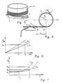
- Fig. 5 is a sketch of an active fiber arrangement in an amplifier in accordance with the invention;
- Fig. 6 is a front view of the fiber shown in Fig. 5;
- Fig. 7 is a diagram showing the variations in the mode diameter in a fiber, depending upon the wavelength;
- Fig. 8 is a diagram showing the gain in an optical amplifier depending upon the length of the active fiber used.
- For the purpose of amplifying signals in optical telecommunications fibers, amplifiers employing optical fibers can be conveniently used; the structure of said amplifiers is diagrammatically shown in Fig. 1, in which 1 denotes an optical telecommunications fiber to which a transmission signal of a wavelength λs, generated by a
signal laser emitter 2 is sent; the signal, being attenuated after a certain line length, is sent to anoptical amplifier 3, substantially consisting of adichroic coupler 4 where it is joined on a singleoutgoing fiber 5, to a pumping signal of wavelength λp, generated by a pumping laser emitter 6; anactive fiber 7 connected to thefiber 5 issuing from the coupler, constitutes the signal amplifying element which is then introduced again into theline fiber 1 and goes on towards its destination. - In order to produce the
active fiber 7 generating the amplification of the light signal, a silica-based optical fiber is used, which is doped with a fluorescent material adapted to generate a light emission which is stimulated in the presence of a light signal that is thus amplified thereby. - As the fluorescent material, it is convenient to use Er₂O₃ which can have stimulated transitions, also referred to as "laser" transitions, at wavelengths that are convenient for the remote transmission of telecommunications signals.
- As shown in the diagram of Fig. 2 relating to a fiber of the above type symbolically representing the available energetic states for an erbium ion solution in the fiber silica-based matrix, the introduction of a light power into the active fiber at the "pumping" wavelength λp, lower than the wavelength λs of the transmission signal, brings a certain number of Er³⁺ ions present as the dopant in the fiber glass-based matrix, to an "excited"
energetic state 8, referred to as "pumping" band, from which state ions spontaneously decay into anenergetic level 9 constituting a laser emission level. - It is known that, while the transition from
band 8 tolevel 9 is associated with a thermal-type emission, which is dispersed outside the fiber (phonon radiation), the transition fromlevel 9 to thebase level 10 generates a light emission of a wavelength corresponding to the energetic value of thelaser emission level 9; if a fiber containing a high amount of ions at the laser emission level is passed through by a signal of a wavelength corresponding to such an emission level, the signal causes the stimulated transition of the concerned ions from the emission state to the base state before the spontaneous decay thereof, with a cascade phenomenon producing the emission of a greatly amplified transmission signal at the outlet of the active fiber. - Diagrammatically shown in fig. 4 is the end of a fiber seen in axial section and denoted by 11; a
core 12 and acladding 13 are defined for such a fiber and they are identified by different refractive indices. - For use purposes as the active fiber in an amplifier, the dopant, that is Er³⁺, is present within the
core 12. - In order to achieve a high amplification gain, it is convenient that the
active fiber 7 in the amplifier be of the single-mode type both at the transmission wavelength and the pumping wavelength, as disclosed in the Italian patent application No. 22120 A/89 in the name of the same applicant. - The foregoing means, as shown in Fig. 3, that based on the teachings contained in said patent the active fiber is such sized that the fiber cut-off wavelength λc1, also referred to as "λcut-off" above which the propagation of the fundamental mode alone occurs in the fiber, is both lower than the wavelength of the transmission signal λs, and lower than the wavelength of the pumping radiation λp.
- The important measurements for the purpose of selecting the cut-off wavelength of the fiber are substantially the numerical aperture NA and core diameter thereof.
- The numerical aperture NA of a fiber having a refractive index profile substantially of the "step index" type or the like is defined as:

where n₁ is the refractive index of the fiber core and n₂ is the refractive index of the fiber cladding. - It is known that the desired refractive indices of the fiber core and cladding can be achieved by selecting the concentration in the core and cladding themselves of the primary dopant, or index variator dopant, introduced into the preform from which the fiber is obtained through well-known techniques.
- The dopants used for the purpose usually consist of GeO₂ or Al₂O₃.
- Within the fiber, a light radiation having a wavelength for which there is a single-mode propagation in the fiber, that is higher than the fiber cut-off wavelength, exhibits a radial distribution of the light intensity of the type shown in Fig. 4 by curves P and S the development of which is substantially of the Gauss type, with a maximum intensity Imax along the fiber axis and decreasing values as far as zero towards the fiber periphery.
- Based on the above distribution a mode diameter φm is defined as the diameter at which there is a light intensity I(φm) in the fiber:

where Imax is the maximum light intensity in the fiber, based on specifications CCITT G.652 (Consultative Committee International Telegram and Telephone). - As is apparent from the drawing, most of the transmitted light power is substantially confined within the mode diameter.
- For the purpose of an efficient amplification it is of great importance to have a high density of the pumping power in the
fiber core 12, where the fluorescent dopant is present, so that a high population inversion in the dopant can be kept, that is a high percentage of dopant atoms available for amplification at thehigher laser level 9, as compared with those at thebase state 10; the pumping power transmitted outside the core where no dopant is present, is substantially inactive to the ends of the dopant inversion at the higher laser level. - The transmission signal, in turn, should have a radial-distribution intensity in the fiber similar to that of the pumping signal, for the purpose of being transmitted to the fiber region in which most of the luminous pumping power is present, so that it can be efficiently amplified.
- To this end therefore the mode diameters of the pumping signal and transmission signal should be as similar as possible.
- In an optical fiber of the type having the
core 12 and cladding 13 as shown in Fig. 4 in alignment with the diagrams of the radial light intensity distribution of pumping and transmission signals, the mode diameter φs at the transmission wavelength λs, the curve of the radial light intensity distribution of which is represented by line S in the drawing, is remarkably greater than the mode diameter φp at the pumping wavelength λp, with the intensity curve P, and substantially corresponding to thecore 12 diameter; the above means that an important part of the light signal does not propagate into the area of the active fiber to which the pumping energy is supplied and in which the dopant is present. - In fact it is to be noted that the mode diameter which for wavelength values close to the cut-off wavelength λc of the fiber is substantially constant and not very different from the core diameter of the fiber itself, for greater λ values greatly increases, as shown in Fig. 7: therefore, in order to ensure that the fiber be single-mode at the pumping wavelength λp, for example in the case of amplifiers having an erbium-doped active fiber, at 980 nm (± 10%), a fiber having a cut-off wavelength λc lower than 980 nm must be used and therefore a very high mode diameter at the transmission wavelength λs is achieved, which is by far greater than the mode diameter at the pumping wavelength λp, so that most of the transmission signal does not propagate into the fiber area in which it can be amplified.
- The above behaviour occurs when the active fiber has a rectilinear or substantially rectilinear configuration, where the term "substantially rectilinear configuration" means that the fiber is not submitted to geometrical deformations capable of greatly modifying the optical behaviour thereof; for said reason, in accordance with the specifications (CCITT, Instruction G.652), it is provided to evaluate the theoretical cut-off wavelength based on the profile of the refractive index in the fiber, and cut-off wavelengths in operating conditions.
- In particular said specifications take into account the possibility of measuring a cut-off wavelength for a wired fiber, the measurement being carried out on a single fiber ring of a radius of 140 mm; the detected variation in the cut-off wavelength in these conditions as compared with the theoretical value is, on the other hand, rather small, a difference lower than about 5% with respect to the theoretical cut-off wavelength being expected.
- In accordance with the present invention the active fiber of the amplifier is selected of the single-mode type at the transmission wavelength λs alone, that is having a value of cut-off wavelength λc2 lower than λs, but substantially higher than λp, as shown in Fig. 3.
- With said fiber the mode diameter at the transmission wavelength, particularly in the range between 1520 and 1570 nm, adapted for the use of amplifiers having an erbium-doped active fiber, being the transmission wavelength close to the cut-off wavelength, appears to be sufficiently small, substantially close to the diameter of the fiber core; the fundamental mode of the pumping signal, in turn, has a diameter close to that of the fiber core and therefore the transmission signal power is maintained substantially confined within the fiber area in which the pumping signal and active dopant are present.
- The active fiber is disposed in a curved configuration over the whole length thereof, in the form of coils constituting the amplifier, as shown in Figs. 5 and 6, for example wound around a cylindrical support or the like: the fiber bending is selected in accordance with the present invention with a radius Rc substantially lower than 140 mm, such as to permit the propagation of the fundamental mode alone within the fiber even for wavelengths lower than the above mentioned wavelength λc2 and in particular even for the pumping wavelength λp.
- The fiber bending in fact causes the same to transmit the fundamental mode alone for wavelengths that are increasingly smaller as the bending imparted to the fiber becomes more marked, that is as Rc becomes smaller; therefore it is possible to define a bending radius Rp under which, for a given wavelength and in particular for the pumping wavelength, the only propagation of the fundamental mode within the fiber is possible.
- The bending radius Rc adopted for the active fiber is to be therefore lower than or equal to the above radius Rp; practically, since the bending can be caused by a mechanical weakening of the fiber structure, making it liable to breakages or crackings, preferably a bending radius equal to Rp or close thereto is used.
- The choice of an appropriate value for said bending enables modes higher than the pumping wavelength to be eliminated from the active fiber, so that within the fiber the fundamental mode of the pumping signal alone is driven, while keeping a cut-off wavelength giving rise to a small mode diameter in the fiber at the transmission wavelength.
- In this manner it is possible to achieve a particularly high amplification efficiency, that is a high amplification gain per supplied pumping power unit, so that a fiber of shorter length can be used to achieve the desired amplification, as shown in Fig. 8, in which one can see that a gain GO can be reached with an active fiber of length L₁, using a fiber of a cut-off length λc2 > 980 nm, greatly lower than the length L₂ necessary to achieve the same gain with a fiber having a cut-off wavelength λc1 < 980 nm.
- In the
dichroic coupler 4 produced on the basis of the teachings disclosed in the above mentioned Italian patent application No. 22120 A/89, thetransport fiber 5 of the transmission signals coupled to the pumping signal is of the single-mode type at both wavelengths; this fiber has therefore a mode diameter at the transmission wavelength λs higher than the mode diameter in the active fiber in accordance with the invention; the welding betweenfibers - A further light attenuation occurs in the welding between the active fiber and the
line fiber 1; in fact although the commercially available fibers used as line fibers are of the single-mode type at the transmission wavelength alone, in said range between 1520 and 1570 nm, they have a rather high mode diameter, for the purpose of achieving easy joinings and the like, equal to or greater than the mode diameter of thecoupler fiber 5. - The overall gain Gex in an amplifier is given by the inner gain of the active fiber Gin, minus losses or attenuations As due to the weldings between the different fibers: in order to achieve this result therefore a gain Gin = Gex + As is required from the active fiber.
- The use of a fiber in accordance with the present invention, having a very small mode diameter, introduces greater losses due to welding as compared with known active fibers which are single-mode also at the wavelength λp, but these additional losses generally appear negligible as compared with the obtained efficiency increase.
- The minimum bending radius Rc of the active fiber of appropriate use is higher than about 20 mm and under this radius the mechanical strength of the curved fiber becomes critical and in addition the welding losses at the junctions take important values, due to the great difference between the mode diameters of the active fiber and line fiber or the fiber coming out of the coupler, whereas bending radii higher than 140 mm are of little utility for achieving an important shifting of the cut-off wavelength; preferably Rc > 35 mm and more preferably 50mm ≦ Rc ≦ 100mm.
- In connection with said bending radii the maximum value of a cut-off wavelength under rectilinear conditions, enabling the single-mode propagation of the pumping signal at 980 nm to be achieved when the fiber is curved to a corresponding bending radius, without reaching said critical values as regards the mechanical strength of the fiber itself is λc = about 1280 nm, corresponding to a mode diameter of about 4 µm; with a bending radius Rc of 50 mm said cut-off wavelength value is λc = about 1100 nm, the mode diameter being equal to about 5.3 µm, whereas the fundamental mode of the pumping signal has a diameter of about 3.8+4 µm.
- For a single-mode fiber in rectilinear conditions at the pumping wavelength, the mode diameter at the wavelength of the transmission signal is higher than 6 µm.
- For the best use of the active fiber qualities in the amplifier in accordance with the invention it is the overall length of the active fiber that should preferably be curved to the provided bending radius, that is the active fiber must be disposed in a curved configuration, for example wound to form coils on the respective support, as diagrammatically shown in Fig. 5, immediately downstream of the joining by welding 15 to the
coupler fiber 5. - Should not the above be possible or desirable, for example in order to avoid the bending stresses given by the curved configuration of the active fiber being transmitted to the
welding 15, which usually constitutes a mechanical weakening point in the fiber, as shown in Fig. 6 the presence of anon-curved portion 16 of active fiber can be accepted, which expedient does not involve a substantial reduction in the advantages given by the active fiber bending. - Preferably the length Lr of the rectilinear or substantially rectilinear
active fiber portion 16, that is having a bending radius greater than Rc as defined above immediately downstream of the coupler, is lower than 400 mm and more preferably Lr ≦ 200 mm; such a substantially rectilinear fiber length can also be accepted at the opposite end of the active fiber, close to its joining to the line fiber, without the amplification efficiency being greatly impaired. - In fact the coupling of the higher modes in the fiber takes place proportionally to the travel length in the fiber itself and therefore after a portion of the stated length no important pumping power transfer takes place in the active fiber from the fundamental mode to higher modes.
- On the other hand, useful results, that is an increase in the amplification efficiency with respect to amplifiers having a single-mode active fiber at the pumping wavelength too can also be obtained, in accordance with the present invention, with an active fiber which is bent only over a portion of the length thereof, should this be needed for meeting requirements of different origin, provided that the portion of bent fiber at the bending radius corresponding to the propagation of the fundamental mode alone of the pumping power, be higher than 70% of the overall fiber length.
- For construction purposes, in particular for keeping the bulkiness of the amplifier structure within reduced limits, the bent fiber portion constitutes the middle portion of the active fiber, whereas the leading and trailing fiber portions, contiguous to the end weldings of the fiber itself, can also have a rectilinear extension; however, due to particular requirements, the active fiber may also have several bent portions alternated with substantially rectilinear portions.
- By way of example an erbium-doped active fiber having the following characteristics has been prepared:

- With the above fiber an amplifier in accordance with the diagram shown in Fig. 1 has been accomplished, in which the fiber has been bent to form contiguous coils having a bending radius R = 50 mm over the whole length thereof; under these conditions a value of the cut-off wavelength has been measured:

- The fiber-using amplifier had the following features:

- The amplifier has been connected to a line fiber having a cut-off wavelength λc (F) = 1100 nm, giving a transmission signal to be amplified in power:

- The amplifier's optical coupler had the fiber carrying the transmission signal and pumping signal of a cut-off wavelength

- Due to the described configuration the following amplification gain has been achieved:

- For comparison an amplifier having the same structural arrangement has been accomplished, using an active fiber having the following features:

- The fiber has been used in the amplifier under substantially rectilinear conditions, in the sense previously shown, so as to induce important variations in the cut-off wavelength thereof.
- The amplifier had the following features:

- The signal to be amplified, carried by an active fiber similar to the one of the preceding example had the following power:

- The following amplification gain has been achieved:

- As can be seen, the amplifier in accordance with the invention has been capable of supplying the same amplification gain as the comparative amplifier using a substantially rectilinear fiber, although a portion of active fiber of shorter length and lower pumping power has been used, thereby showing a remarkably greater efficiency.
- The support structure for the coiled fiber turns, adapted to keep them at the provided bending radius, can be of any kind, also depending upon the structural features of the amplifier envelope, and it is not therefore described in detail.
- Many variations can be made without departing from the scope of the general features of the present invention.
Claims (8)
- An optical amplifier, in particular for optical-fiber telecommunications lines insertable in series in an optical fiber of a line, comprising at least a luminous pumping source (6), a dichroic coupler (4) having two inputs connected to the optical line fiber carrying a transmission signal and to the luminous pumping source respectively, and an output (5) connected to one end of an active fiber (7) containing a fluorescent dopant in the respective optical core, with emission in the wavelength range of the transmission signal and to be pumped at the wavelength of the pumping source, characterized in that the active optical fiber (7) is a fiber that in a substantially rectilinear configuration permits the luminous single-mode propagation at the transmission wavelength and the luminous multi-mode propagation at the pumping wavelength and is disposed in a curved configuration at least over 70% of its overall length, with a bending radius corresponding to the propagation in the fiber of the fundamental mode alone at the pumping wavelength.
- An optical amplifier according to claim 1, characterized in that the active fiber (7) is curved so as to have its bending radius in the range of 20 to 140 mm.
- An optical amplifier according to claim 2, characterized in that the bending radius of the active fiber ranges between 35 and 100 mm.
- An optical amplifier according to claim 1, characterized in that the transmission wavelength is in the range of 1520 to 1570 nm and the pumping wavelength is 980 nm (± 10 nm) and the fluorescent dopant in the active fiber is erbium.
- An optical amplifier according to claim 1, characterized in that the active fiber (7) exhibits at least a curved portion (11) having a bending radius corresponding to the propagation in the fiber itself of the fundamental mode alone at the pumping wavelength, which portion is contiguous to non-curved fiber portions (16), the length of the curved portion or the sum of the curved portion lengths being higher than 70% of the overall length of the active fiber.
- An optical amplifier according to claim 5, characterized in that the active fiber (7) exhibits a single continuous curved portion (11) having a bending radius corresponding to the propagation in the fiber itself of the fundamental mode alone at the pumping wavelength, non-curved fiber portions (16) being present at either or both of the active fiber ends.
- An optical amplifier according to claim 6, characterized in that the active fiber (7) is curved according to a bending radius corresponding to the propagation in the fiber itself of the fundamental mode alone at the pumping wavelength over the whole length thereof, apart from the end portions (16), which are substantially devoid of bending and have each a length lower than 400 mm.
- An optical amplifier according to claim 7, characterized in that the end portions (16) that are substantially devoid of bending have a length lower than 200 mm.
Applications Claiming Priority (2)
| Application Number | Priority Date | Filing Date | Title |
|---|---|---|---|
| IT1934190 | 1990-02-12 | ||
| IT01934190A IT1237980B (en) | 1990-02-12 | 1990-02-12 | CURVED SINGLE-MODE ACTIVE FIBER OPTICAL AMPLIFIER |
Publications (2)
| Publication Number | Publication Date |
|---|---|
| EP0442553A1 true EP0442553A1 (en) | 1991-08-21 |
| EP0442553B1 EP0442553B1 (en) | 1995-03-08 |
Family
ID=11156892
Family Applications (1)
| Application Number | Title | Priority Date | Filing Date |
|---|---|---|---|
| EP91200156A Expired - Lifetime EP0442553B1 (en) | 1990-02-12 | 1991-01-26 | Optical amplifier having a single-mode curved active fibre |
Country Status (26)
| Country | Link |
|---|---|
| US (1) | US5161050A (en) |
| EP (1) | EP0442553B1 (en) |
| JP (1) | JP3239124B2 (en) |
| KR (1) | KR0178393B1 (en) |
| CN (1) | CN1024299C (en) |
| AR (1) | AR247795A1 (en) |
| AT (1) | ATE119690T1 (en) |
| AU (1) | AU642698B2 (en) |
| BR (1) | BR9100633A (en) |
| CA (1) | CA2034797C (en) |
| CZ (1) | CZ280356B6 (en) |
| DE (1) | DE69107872T2 (en) |
| DK (1) | DK0442553T3 (en) |
| ES (1) | ES2072523T3 (en) |
| FI (1) | FI104294B (en) |
| HK (1) | HK2596A (en) |
| HU (1) | HU216235B (en) |
| IE (1) | IE67357B1 (en) |
| IT (1) | IT1237980B (en) |
| MY (1) | MY105414A (en) |
| NO (1) | NO302326B1 (en) |
| PE (1) | PE17791A1 (en) |
| PL (1) | PL164373B1 (en) |
| PT (1) | PT96736B (en) |
| RU (1) | RU2086062C1 (en) |
| SK (1) | SK278814B6 (en) |
Cited By (11)
| Publication number | Priority date | Publication date | Assignee | Title |
|---|---|---|---|---|
| WO1992011561A1 (en) * | 1990-12-24 | 1992-07-09 | Standard Elektrik Lorenz Aktiengesellschaft | Optical amplifier |
| GB2266620A (en) * | 1992-04-27 | 1993-11-03 | Univ Southampton | Optical power limited amplifier |
| US5499135A (en) * | 1990-12-24 | 1996-03-12 | Alcatel N.V. | Optical amplifier |
| WO1998025326A1 (en) * | 1996-12-04 | 1998-06-11 | University Of Southampton | Optical amplifier and light source |
| GB2335074A (en) * | 1996-12-04 | 1999-09-08 | Univ Southampton | Optical amplifier and light source |
| US6243196B1 (en) | 1999-05-20 | 2001-06-05 | Sumitomo Electric Industries, Ltd. | Optical fiber for optical amplifier and fiber optic amplifier |
| WO2001069313A1 (en) | 2000-03-10 | 2001-09-20 | The Government Of The United States Of America As Represented By The Secretary Of The Navy | Helical fiber amplifier |
| EP1281989A2 (en) * | 2001-07-31 | 2003-02-05 | The Furukawa Electric Co., Ltd. | Optical fiber and optical transmission method |
| WO2004095655A1 (en) * | 2003-04-01 | 2004-11-04 | Corning Incorporated | Reduced clad diameter rare earth doped fiber coils and optical amplifiers utiliying such coils |
| US6978078B2 (en) | 2004-01-08 | 2005-12-20 | Corning Incorporated | Reduced clad diameter rare earth doped fiber coils and optical amplifiers utilizing such coils |
| US8873593B2 (en) | 1998-11-25 | 2014-10-28 | Imra America, Inc. | Mode-locked multi-mode fiber laser pulse source |
Families Citing this family (21)
| Publication number | Priority date | Publication date | Assignee | Title |
|---|---|---|---|---|
| FR2659755B1 (en) * | 1990-03-16 | 1992-05-29 | Alcatel Nv | ERBIUM DOPED FIBER OPTICAL AMPLIFIER. |
| FR2675649B1 (en) * | 1991-04-22 | 1993-07-16 | Alcatel Nv | TELECOMMUNICATIONS SYSTEM WITH FIBER OPTICAL AMPLIFIERS FOR THE TRANSMISSION OF LONG DISTANCE SIGNALS. |
| ES2079094T3 (en) * | 1991-05-18 | 1996-01-01 | Alcatel Nv | OPTICAL INFORMATION TRANSMISSION SYSTEM WITH OPTICAL CONTROL OF AN OPTICAL AMPLIFIER OR WITH CONVERSION OF THE WAVE LENGTH OF THE OPTICAL SIGNAL. |
| JP2648643B2 (en) * | 1991-06-03 | 1997-09-03 | 日本電信電話株式会社 | Optical amplifier |
| BE1007071A3 (en) * | 1993-04-28 | 1995-03-07 | Philips Electronics Nv | Optical systems. |
| US5818630A (en) * | 1997-06-25 | 1998-10-06 | Imra America, Inc. | Single-mode amplifiers and compressors based on multi-mode fibers |
| US6122413A (en) * | 1998-10-20 | 2000-09-19 | Optigain, Inc. | Fiber optic transmitter |
| US6236497B1 (en) * | 1998-11-30 | 2001-05-22 | Lucent Technologies Inc. | Direct free space pump signal mixing for EDFA |
| US6192179B1 (en) | 1999-01-25 | 2001-02-20 | Corning Incorporated | Distributed resonant ring fiber filter |
| CA2371100C (en) * | 1999-04-30 | 2012-10-02 | University Of Southampton | An optical fibre arrangement |
| CN1275364C (en) * | 1999-05-28 | 2006-09-13 | 住友电气工业株式会社 | Optical fibre and optical fibre amplifier for light amplification |
| US6256138B1 (en) * | 2000-01-07 | 2001-07-03 | Lucent Technologies Inc | Fiber filter to improve return loss at signal band of a fiber amplifier for pump laser modules |
| US6550279B1 (en) | 2000-09-01 | 2003-04-22 | Corning Incorporated | Process for drawing optical fiber from a multiple crucible apparatus with a thermal gradient |
| US6588235B2 (en) | 2001-08-30 | 2003-07-08 | Corning Incorporated | Method of centering a fiber core in a multiple-crucible method |
| US7000894B2 (en) * | 2003-04-25 | 2006-02-21 | Pur Water Purification Products, Inc. | Fluidic cartridges and end pieces thereof |
| DE102004035795A1 (en) * | 2004-07-23 | 2006-02-16 | Siemens Ag | Optical amplifier with pump module |
| EP1650839A1 (en) * | 2004-10-20 | 2006-04-26 | Wavelight Laser Technologie AG | Fiber laser arrangement |
| US7760423B2 (en) | 2005-07-20 | 2010-07-20 | Sumitomo Electric Industries, Ltd. | Optical amplifier |
| JP5476576B2 (en) * | 2007-03-12 | 2014-04-23 | 独立行政法人情報通信研究機構 | Burst-mode erbium-doped fiber amplifier |
| JP2012237714A (en) * | 2011-05-13 | 2012-12-06 | Sony Corp | Nonlinear raman spectroscopic apparatus, microspectroscopic apparatus, and microspectroscopic imaging apparatus |
| CN106772550B (en) * | 2017-02-10 | 2019-02-22 | 东莞理工学院 | Fibre-optical bending disappears mold device, method |
Citations (3)
| Publication number | Priority date | Publication date | Assignee | Title |
|---|---|---|---|---|
| EP0189196A2 (en) * | 1985-01-25 | 1986-07-30 | Polaroid Corporation | Raman amplified filter tap system |
| US4784450A (en) * | 1984-10-15 | 1988-11-15 | Hughes Aircraft Company | Apparatus for generating and amplifying new wavelengths of optical radiation |
| US4941726A (en) * | 1988-08-31 | 1990-07-17 | The Unites States Of America As Represented By The Secretary Of The Navy | Tapered fiber amplifier |
Family Cites Families (9)
| Publication number | Priority date | Publication date | Assignee | Title |
|---|---|---|---|---|
| US3964131A (en) * | 1973-07-26 | 1976-06-22 | Borden, Inc. | Method and apparatus for eviscerating clams |
| US4556279A (en) * | 1981-11-09 | 1985-12-03 | Board Of Trustees Of The Leland Stanford Junior University | Passive fiber optic multiplexer |
| FR2573547B1 (en) * | 1984-11-16 | 1987-04-10 | Thomson Csf | SINGLE-MODE OPTICAL SOURCE AND OPTICAL AMPLIFIER DEVICE TUNABLE IN THE NEAR INFRARED AND APPLICATION TO SELECTIVE AMPLIFIER AND REGENERATION DEVICES |
| US4815804A (en) * | 1985-02-08 | 1989-03-28 | The Board Of Trustees Of The Leland Stanford Junior University | In-line fiber optic memory and method of using same |
| US4712075A (en) * | 1985-11-27 | 1987-12-08 | Polaroid Corporation | Optical amplifier |
| US4915468A (en) * | 1987-02-20 | 1990-04-10 | The Board Of Trustees Of The Leland Stanford Junior University | Apparatus using two-mode optical waveguide with non-circular core |
| US4741586A (en) * | 1987-02-20 | 1988-05-03 | The Board Of Trustees Of The Leland Stanford Junior University | Dynamic coupler using two-mode optical waveguides |
| GB8724736D0 (en) * | 1987-10-22 | 1987-11-25 | British Telecomm | Optical fibre |
| US4815079A (en) * | 1987-12-17 | 1989-03-21 | Polaroid Corporation | Optical fiber lasers and amplifiers |
-
1990
- 1990-02-12 IT IT01934190A patent/IT1237980B/en active IP Right Grant
-
1991
- 1991-01-16 US US07/642,221 patent/US5161050A/en not_active Expired - Lifetime
- 1991-01-23 CA CA002034797A patent/CA2034797C/en not_active Expired - Fee Related
- 1991-01-26 AT AT91200156T patent/ATE119690T1/en not_active IP Right Cessation
- 1991-01-26 EP EP91200156A patent/EP0442553B1/en not_active Expired - Lifetime
- 1991-01-26 DE DE69107872T patent/DE69107872T2/en not_active Expired - Lifetime
- 1991-01-26 DK DK91200156.7T patent/DK0442553T3/en active
- 1991-01-26 ES ES91200156T patent/ES2072523T3/en not_active Expired - Lifetime
- 1991-01-31 MY MYPI91000151A patent/MY105414A/en unknown
- 1991-02-06 AU AU70818/91A patent/AU642698B2/en not_active Ceased
- 1991-02-07 CZ CS91300A patent/CZ280356B6/en not_active IP Right Cessation
- 1991-02-07 SK SK300-91A patent/SK278814B6/en unknown
- 1991-02-08 PE PE1991181413A patent/PE17791A1/en not_active Application Discontinuation
- 1991-02-08 AR AR91319010A patent/AR247795A1/en active
- 1991-02-08 BR BR919100633A patent/BR9100633A/en not_active IP Right Cessation
- 1991-02-08 HU HU91420A patent/HU216235B/en not_active IP Right Cessation
- 1991-02-11 FI FI910649A patent/FI104294B/en active
- 1991-02-11 RU SU914894653A patent/RU2086062C1/en not_active IP Right Cessation
- 1991-02-11 PL PL91289030A patent/PL164373B1/en unknown
- 1991-02-11 PT PT96736A patent/PT96736B/en not_active IP Right Cessation
- 1991-02-11 IE IE44091A patent/IE67357B1/en not_active IP Right Cessation
- 1991-02-11 NO NO910530A patent/NO302326B1/en not_active IP Right Cessation
- 1991-02-12 CN CN91100926A patent/CN1024299C/en not_active Expired - Fee Related
- 1991-02-12 KR KR1019910002299A patent/KR0178393B1/en not_active IP Right Cessation
- 1991-02-12 JP JP01896991A patent/JP3239124B2/en not_active Expired - Fee Related
-
1996
- 1996-01-04 HK HK2596A patent/HK2596A/en not_active IP Right Cessation
Patent Citations (3)
| Publication number | Priority date | Publication date | Assignee | Title |
|---|---|---|---|---|
| US4784450A (en) * | 1984-10-15 | 1988-11-15 | Hughes Aircraft Company | Apparatus for generating and amplifying new wavelengths of optical radiation |
| EP0189196A2 (en) * | 1985-01-25 | 1986-07-30 | Polaroid Corporation | Raman amplified filter tap system |
| US4941726A (en) * | 1988-08-31 | 1990-07-17 | The Unites States Of America As Represented By The Secretary Of The Navy | Tapered fiber amplifier |
Cited By (22)
| Publication number | Priority date | Publication date | Assignee | Title |
|---|---|---|---|---|
| WO1992011561A1 (en) * | 1990-12-24 | 1992-07-09 | Standard Elektrik Lorenz Aktiengesellschaft | Optical amplifier |
| US5499135A (en) * | 1990-12-24 | 1996-03-12 | Alcatel N.V. | Optical amplifier |
| GB2266620A (en) * | 1992-04-27 | 1993-11-03 | Univ Southampton | Optical power limited amplifier |
| GB2266620B (en) * | 1992-04-27 | 1996-08-28 | Univ Southampton | Optical power limited amplifier |
| US5579153A (en) * | 1992-04-27 | 1996-11-26 | Pirelli Cavi S.P.A. | Optical power limiting amplifier |
| GB2335074B (en) * | 1996-12-04 | 2002-02-13 | Univ Southampton | Optical Amplifier |
| GB2335074A (en) * | 1996-12-04 | 1999-09-08 | Univ Southampton | Optical amplifier and light source |
| US6288835B1 (en) | 1996-12-04 | 2001-09-11 | Lars Johan Albinsson Nilsson | Optical amplifiers and light source |
| WO1998025326A1 (en) * | 1996-12-04 | 1998-06-11 | University Of Southampton | Optical amplifier and light source |
| US9595802B2 (en) | 1998-11-25 | 2017-03-14 | Imra America, Inc. | Multi-mode fiber amplifier |
| US9570880B2 (en) | 1998-11-25 | 2017-02-14 | Imra America, Inc. | Multi-mode fiber amplifier |
| US8873593B2 (en) | 1998-11-25 | 2014-10-28 | Imra America, Inc. | Mode-locked multi-mode fiber laser pulse source |
| US6577440B2 (en) | 1999-05-20 | 2003-06-10 | Sumitomo Electric Industries, Ltd. | Optical fiber for optical amplifier and fiber optic amplifier |
| US6538806B2 (en) | 1999-05-20 | 2003-03-25 | Sumitomo Electric Industries, Ltd. | Optical fiber for optical amplifier and fiber optic amplifier |
| US6771415B2 (en) | 1999-05-20 | 2004-08-03 | Sumitomo Electric Industries, Ltd. | Optical fiber for optical amplifier and fiber optic amplifier |
| US6243196B1 (en) | 1999-05-20 | 2001-06-05 | Sumitomo Electric Industries, Ltd. | Optical fiber for optical amplifier and fiber optic amplifier |
| US6496301B1 (en) * | 2000-03-10 | 2002-12-17 | The United States Of America As Represented By The Secretary Of The Navy | Helical fiber amplifier |
| WO2001069313A1 (en) | 2000-03-10 | 2001-09-20 | The Government Of The United States Of America As Represented By The Secretary Of The Navy | Helical fiber amplifier |
| EP1281989A2 (en) * | 2001-07-31 | 2003-02-05 | The Furukawa Electric Co., Ltd. | Optical fiber and optical transmission method |
| EP1281989A3 (en) * | 2001-07-31 | 2004-12-29 | The Furukawa Electric Co., Ltd. | Optical fiber and optical transmission method |
| WO2004095655A1 (en) * | 2003-04-01 | 2004-11-04 | Corning Incorporated | Reduced clad diameter rare earth doped fiber coils and optical amplifiers utiliying such coils |
| US6978078B2 (en) | 2004-01-08 | 2005-12-20 | Corning Incorporated | Reduced clad diameter rare earth doped fiber coils and optical amplifiers utilizing such coils |
Also Published As
Similar Documents
| Publication | Publication Date | Title |
|---|---|---|
| EP0442553B1 (en) | Optical amplifier having a single-mode curved active fibre | |
| USRE38298E1 (en) | Double-core active fiber optical amplifier having a wide-band signal wavelength | |
| US6490078B2 (en) | Optical fiber for optical amplifier, optical fiber amplifier and optical fiber laser | |
| CN102136669A (en) | Double clad fiber laser device | |
| US6577440B2 (en) | Optical fiber for optical amplifier and fiber optic amplifier | |
| US5218665A (en) | Double core, active fiber optical amplifier having a wide band signal wavelength | |
| EP2625753B1 (en) | High power neodymium fiber lasers and amplifiers | |
| JPH0563259A (en) | Optical fiber amplifier | |
| EP0441211B1 (en) | Active fibre optical amplifier, with double-core portions, having a wide signal wavelength band | |
| JPH06216440A (en) | Multicore fiber with rare earth element added | |
| JPH0492484A (en) | Optical amplifier and optical oscillator | |
| JP3558714B2 (en) | Optical fiber amplifier and optical fiber laser | |
| JPH0473718A (en) | Optical amplifier | |
| JPH0473980A (en) | Optical amplifier | |
| JPH02239236A (en) | Optical amplifier device |
Legal Events
| Date | Code | Title | Description |
|---|---|---|---|
| PUAI | Public reference made under article 153(3) epc to a published international application that has entered the european phase |
Free format text: ORIGINAL CODE: 0009012 |
|
| AK | Designated contracting states |
Kind code of ref document: A1 Designated state(s): AT BE CH DE DK ES FR GB IT LI LU NL SE |
|
| RAP1 | Party data changed (applicant data changed or rights of an application transferred) |
Owner name: PIRELLI CAVI S.P.A. |
|
| 17P | Request for examination filed |
Effective date: 19920211 |
|
| 17Q | First examination report despatched |
Effective date: 19930827 |
|
| RAP1 | Party data changed (applicant data changed or rights of an application transferred) |
Owner name: PIRELLI CAVI S.P.A. |
|
| GRAA | (expected) grant |
Free format text: ORIGINAL CODE: 0009210 |
|
| AK | Designated contracting states |
Kind code of ref document: B1 Designated state(s): AT BE CH DE DK ES FR GB IT LI LU NL SE |
|
| REF | Corresponds to: |
Ref document number: 119690 Country of ref document: AT Date of ref document: 19950315 Kind code of ref document: T |
|
| ITF | It: translation for a ep patent filed |
Owner name: MARCHI & MITTLER S.R.L. |
|
| REF | Corresponds to: |
Ref document number: 69107872 Country of ref document: DE Date of ref document: 19950413 |
|
| REG | Reference to a national code |
Ref country code: CH Ref legal event code: PL |
|
| ET | Fr: translation filed | ||
| REG | Reference to a national code |
Ref country code: ES Ref legal event code: FG2A Ref document number: 2072523 Country of ref document: ES Kind code of ref document: T3 |
|
| REG | Reference to a national code |
Ref country code: DK Ref legal event code: T3 |
|
| PLBI | Opposition filed |
Free format text: ORIGINAL CODE: 0009260 |
|
| PLBQ | Unpublished change to opponent data |
Free format text: ORIGINAL CODE: EPIDOS OPPO |
|
| 26 | Opposition filed |
Opponent name: CORNING INCORPORATED Effective date: 19951208 |
|
| NLR1 | Nl: opposition has been filed with the epo |
Opponent name: CORNING INCORPORATED |
|
| PLBF | Reply of patent proprietor to notice(s) of opposition |
Free format text: ORIGINAL CODE: EPIDOS OBSO |
|
| REG | Reference to a national code |
Ref country code: CH Ref legal event code: NV Representative=s name: FIAMMENGHI-FIAMMENGHI Ref country code: CH Ref legal event code: AEN Free format text: CONFORMEMENTE ALL'ART. 47 LBI IL BREVETTO E STATO RIMESSO IN VIGORE IL 30.05.1996 SULLA BASE DELLA DOMANDA DI REINTEGRAZIONE NELLO STATO ANTERIORE PRESENTATA IL 20.03.1995. |
|
| PLBF | Reply of patent proprietor to notice(s) of opposition |
Free format text: ORIGINAL CODE: EPIDOS OBSO |
|
| PLBF | Reply of patent proprietor to notice(s) of opposition |
Free format text: ORIGINAL CODE: EPIDOS OBSO |
|
| PLBO | Opposition rejected |
Free format text: ORIGINAL CODE: EPIDOS REJO |
|
| APAC | Appeal dossier modified |
Free format text: ORIGINAL CODE: EPIDOS NOAPO |
|
| APAE | Appeal reference modified |
Free format text: ORIGINAL CODE: EPIDOS REFNO |
|
| APAC | Appeal dossier modified |
Free format text: ORIGINAL CODE: EPIDOS NOAPO |
|
| APAC | Appeal dossier modified |
Free format text: ORIGINAL CODE: EPIDOS NOAPO |
|
| PLBN | Opposition rejected |
Free format text: ORIGINAL CODE: 0009273 |
|
| STAA | Information on the status of an ep patent application or granted ep patent |
Free format text: STATUS: OPPOSITION REJECTED |
|
| 27O | Opposition rejected |
Effective date: 20000112 |
|
| NLR2 | Nl: decision of opposition | ||
| PGFP | Annual fee paid to national office [announced via postgrant information from national office to epo] |
Ref country code: DK Payment date: 20011213 Year of fee payment: 12 |
|
| PGFP | Annual fee paid to national office [announced via postgrant information from national office to epo] |
Ref country code: NL Payment date: 20011214 Year of fee payment: 12 |
|
| PGFP | Annual fee paid to national office [announced via postgrant information from national office to epo] |
Ref country code: LU Payment date: 20011221 Year of fee payment: 12 |
|
| REG | Reference to a national code |
Ref country code: GB Ref legal event code: IF02 |
|
| PGFP | Annual fee paid to national office [announced via postgrant information from national office to epo] |
Ref country code: SE Payment date: 20020107 Year of fee payment: 12 |
|
| PGFP | Annual fee paid to national office [announced via postgrant information from national office to epo] |
Ref country code: ES Payment date: 20020117 Year of fee payment: 12 |
|
| PGFP | Annual fee paid to national office [announced via postgrant information from national office to epo] |
Ref country code: BE Payment date: 20020220 Year of fee payment: 12 |
|
| PGFP | Annual fee paid to national office [announced via postgrant information from national office to epo] |
Ref country code: CH Payment date: 20020325 Year of fee payment: 12 |
|
| REG | Reference to a national code |
Ref country code: FR Ref legal event code: TP |
|
| REG | Reference to a national code |
Ref country code: FR Ref legal event code: TP |
|
| PGFP | Annual fee paid to national office [announced via postgrant information from national office to epo] |
Ref country code: GB Payment date: 20021210 Year of fee payment: 13 |
|
| PG25 | Lapsed in a contracting state [announced via postgrant information from national office to epo] |
Ref country code: LU Free format text: LAPSE BECAUSE OF NON-PAYMENT OF DUE FEES Effective date: 20030126 |
|
| PG25 | Lapsed in a contracting state [announced via postgrant information from national office to epo] |
Ref country code: SE Free format text: LAPSE BECAUSE OF NON-PAYMENT OF DUE FEES Effective date: 20030127 Ref country code: ES Free format text: LAPSE BECAUSE OF NON-PAYMENT OF DUE FEES Effective date: 20030127 |
|
| PG25 | Lapsed in a contracting state [announced via postgrant information from national office to epo] |
Ref country code: BE Free format text: LAPSE BECAUSE OF NON-PAYMENT OF DUE FEES Effective date: 20030131 Ref country code: LI Free format text: LAPSE BECAUSE OF NON-PAYMENT OF DUE FEES Effective date: 20030131 Ref country code: CH Free format text: LAPSE BECAUSE OF NON-PAYMENT OF DUE FEES Effective date: 20030131 Ref country code: DK Free format text: LAPSE BECAUSE OF NON-PAYMENT OF DUE FEES Effective date: 20030131 |
|
| PG25 | Lapsed in a contracting state [announced via postgrant information from national office to epo] |
Ref country code: NL Free format text: LAPSE BECAUSE OF NON-PAYMENT OF DUE FEES Effective date: 20030801 |
|
| EUG | Se: european patent has lapsed | ||
| REG | Reference to a national code |
Ref country code: DK Ref legal event code: EBP |
|
| REG | Reference to a national code |
Ref country code: CH Ref legal event code: PL |
|
| NLV4 | Nl: lapsed or anulled due to non-payment of the annual fee |
Effective date: 20030801 |
|
| PGFP | Annual fee paid to national office [announced via postgrant information from national office to epo] |
Ref country code: AT Payment date: 20040102 Year of fee payment: 14 |
|
| PG25 | Lapsed in a contracting state [announced via postgrant information from national office to epo] |
Ref country code: GB Free format text: LAPSE BECAUSE OF NON-PAYMENT OF DUE FEES Effective date: 20040126 |
|
| REG | Reference to a national code |
Ref country code: ES Ref legal event code: FD2A Effective date: 20030127 |
|
| GBPC | Gb: european patent ceased through non-payment of renewal fee |
Effective date: 20040126 |
|
| PG25 | Lapsed in a contracting state [announced via postgrant information from national office to epo] |
Ref country code: AT Free format text: LAPSE BECAUSE OF NON-PAYMENT OF DUE FEES Effective date: 20050126 |
|
| APAH | Appeal reference modified |
Free format text: ORIGINAL CODE: EPIDOSCREFNO |
|
| PGFP | Annual fee paid to national office [announced via postgrant information from national office to epo] |
Ref country code: IT Payment date: 20100127 Year of fee payment: 20 Ref country code: FR Payment date: 20100205 Year of fee payment: 20 |
|
| PGFP | Annual fee paid to national office [announced via postgrant information from national office to epo] |
Ref country code: DE Payment date: 20100127 Year of fee payment: 20 |
|
| PG25 | Lapsed in a contracting state [announced via postgrant information from national office to epo] |
Ref country code: DE Free format text: LAPSE BECAUSE OF EXPIRATION OF PROTECTION Effective date: 20110126 |