EP0442566A1 - Information recording device - Google Patents
Information recording device Download PDFInfo
- Publication number
- EP0442566A1 EP0442566A1 EP91200257A EP91200257A EP0442566A1 EP 0442566 A1 EP0442566 A1 EP 0442566A1 EP 91200257 A EP91200257 A EP 91200257A EP 91200257 A EP91200257 A EP 91200257A EP 0442566 A1 EP0442566 A1 EP 0442566A1
- Authority
- EP
- European Patent Office
- Prior art keywords
- record carrier
- recording device
- information
- adjustment data
- information recording
- Prior art date
- Legal status (The legal status is an assumption and is not a legal conclusion. Google has not performed a legal analysis and makes no representation as to the accuracy of the status listed.)
- Granted
Links
Images


Classifications
-
- G—PHYSICS
- G11—INFORMATION STORAGE
- G11B—INFORMATION STORAGE BASED ON RELATIVE MOVEMENT BETWEEN RECORD CARRIER AND TRANSDUCER
- G11B11/00—Recording on or reproducing from the same record carrier wherein for these two operations the methods are covered by different main groups of groups G11B3/00 - G11B7/00 or by different subgroups of group G11B9/00; Record carriers therefor
- G11B11/12—Recording on or reproducing from the same record carrier wherein for these two operations the methods are covered by different main groups of groups G11B3/00 - G11B7/00 or by different subgroups of group G11B9/00; Record carriers therefor using recording by optical means
-
- G—PHYSICS
- G11—INFORMATION STORAGE
- G11B—INFORMATION STORAGE BASED ON RELATIVE MOVEMENT BETWEEN RECORD CARRIER AND TRANSDUCER
- G11B7/00—Recording or reproducing by optical means, e.g. recording using a thermal beam of optical radiation by modifying optical properties or the physical structure, reproducing using an optical beam at lower power by sensing optical properties; Record carriers therefor
- G11B7/004—Recording, reproducing or erasing methods; Read, write or erase circuits therefor
- G11B7/0045—Recording
Definitions
- the invention relates to an information recording device comprising write means for providing the record carrier with information patterns, means for determining record carrier dependent adjustment data, adjustment means for adjusting the write means in conformity with the determined adjustment data, the means for determining the adjustment data being adapted to record information patterns for different settings of the write means and to determine, on the basis of the recorded information pattern, the adjustment data in accordance with a predetermined criterion.
- Such a device is known from US 4,631,713.
- the adjustment data is determined every time that the record carrier is introduced into the device.
- a drawback of the known device is that it takes a comparatively long time to determine the optimum adjustment.
- the information recording device further comprises storage means for storing in a memory the determined adjustment data together with identification data indicative of the combination of the recording device and the record carrier for which the adjustment data has been determined, and detection means for detecting, after insertion of a record carrier into the information recording device, whether adjustment data for the relevant combination of a record carrier and information recording device has been stored in the memory, the adjustment means being adapted to adjust the write means in conformity with the adjustment data in the case that adjustment data for the said combination has been stored.
- the invention is based on inter alia the recognition of the fact that the optimum adjustment of the write means is found to change hardly in the course of time.
- the adjustment has to be determined only once for a specific combination of a record carrier and an information recording device, so that the time required for determining the adjustment data is also minimised.
- the storage means are adapted to store in a memory of the information recording device the determined adjustment data together with the record carrier identification code indicative of the record carrier for which the data has been determined, the recording device comprising read means for reading a record carrier identification code which may be present on the record carrier, the detection means being adapted to determine whether adjustment data for the record carrier identification thus read has been stored in the memory of the device.
- the last-mentioned embodiment has the advantage that the adjustment data occupies a minimal space on the record carrier.
- the record carrier identification can be applied during manufacture of the record carrier.
- the master employed in the fabrication of the record carriers is provided with an identification pattern.
- the problem which then occurs is that a complete series of the record carriers has the same record carrier identification code. Since the recording parameters of the record carriers may vary within one series of record carriers it is possible that if two record carriers of the same series are employed in the same information recording device the information patterns are not recorded in an optimum manner for both record carriers.
- the device comprises means for providing the record carrier with a record carrier identification.
- the information recording device then comprises a random-code generator for generating the record carrier identification to be recorded. This minimizes the likelihood of the same record carrier identification being recorded in the case of mass or series produced information recording devices. Thus the likelihood of a non-optimum adjustment when the same record carrier is used in different information recording devices is minimized.
- the device in accordance with the invention is particularly suitable for use in apparatus in which the linear velocity with which the record carrier is scanned during the recording of the information patterns is constant. In that case the changes in the recording conditions are minimal, so that a previously determined optimum adjustment of the write means need not be adapted.
- the invention is not limited to device with a constant linear scanning velocity during recording. It can also be employed in systems with variable scanning velocities, in which the scanning velocity has no influence or a predictable influence on the adjustment of the write means.
- Fig. 1 by way of example shows an embodiment of an information recording device in accordance with the invention.
- the present embodiment is a recording device by means of which information can be recorded on a record carrier 1, for example an optical record carrier, which is rotated about an axis 2.
- the information recording device comprises a customary write head 3, arranged opposite the rotating record carrier 1.
- a customary positioning system for example in the form of a motor 4 and a spindle 5
- the read-write head 3 can be moved in a radial direction relative to the record carrier 1 under control of a customary control unit 6, which comprises for example a microprocessor.
- An information signal Vi to be recorded can be applied to a signal processing circuit 7 via an input 6.
- the signal processing circuit 7 is of a customary type, which converts the applied input signal into a recording signal Vop of a suitable recording format, for example a CD format.
- the recording signal Vop is applied to a driver circuit 8 of a customary type, which converts the recording signal Vop into a drive signal Vs for the read/write head 3 in such a way that an information pattern corresponding to the recording signal Vop is recorded on the record carrier.
- the read/write head 3 has an output for supplying a read signal Vl which is representative of the information pattern being read.
- the read signal Vl is applied to a read circuit 9 for recovering the information represented by the read signal.
- the driver circuit 8 is of an adjustable type, enabling one or more of the parameters with which the quality of the recorded information pattern can be influenced to be adjusted.
- an optical read/write head is used by which an information pattern of optically detectable effects is formed by means of a radiation beam
- the intensity of the radiation beam is an important parameter which largely dictates the quality of the information pattern.
- the read/write head is a magnetic or magneto-optical write head which generates a magnetic field for the purpose of forming an information pattern in the form of magnetic effects (domains)
- the field strength of the generated magnetic field may be an important adjustment parameter.
- the pulse width may be an important adjustment parameter.
- the above-mentioned adjustment parameters are only few examples of the large number of adjustment parameters which are possible.
- the adjustment parameter is a reference value for the speed with which the effects are formed.
- the intensity of the write beam is controlled to maintain the speed with which the effects are formed at the adjusted reference value.
- the device For determining the optimum adjustment of the driver circuit 8 the device comprises an analysis circuit 10, which derives from the read signal an analysis signal which is indicative of the quality of the information pattern being read.
- the optimum adjustment can be determined by forming test information patterns on the record carrier 1 for different settings of the driver circuit and by selecting, on the basis of the analysis signal Va, that setting for which the analysis signal indicates an optimum quality.
- the information signal Vi may be employed for writing the test information pattern.
- a test signal generator 11 for this purpose, which may then be included, for example, in the signal processing circuit 7.
- the optimum adjustment is determined under control of the control unit 15, which for this purpose is coupled to the analysis circuit 10, to the driver circuit 8, and to the test signal generator 11, if present, which control unit is loaded with a suitable program or comprises a suitable hardware circuit.
- the optimum adjustment is determined in a calibration procedure, which is carried out after a record carrier has been inserted in the information recording device for the first time.
- the optimum adjustment data and the identification data which are indicative of the combination of a record carrier and recording device are subsequently stored. When the same record carrier is reinserted into the recording device the stored adjustment data can then be employed again, so that it is not necessary to carry out a new calibration procedure. This saves a considerable amount of time.
- this adjustment data may be stored both on the record carrier itself and in a memory 12 of the information recording device.
- the adjustment data is stored on the record carrier identification data in the form of a device identification can be recorded together with the adjustment data.
- the device identiciation recorded on the record carrier After a record carrier has been loaded into the information recording device it is then possible on the basis of the device identiciation recorded on the record carrier to detect unambiguously whether the adjustment data has already been determined for the relevant combination of a record carrier and an information recording device. If this is the case a calibration procedure is not necessary and the driver circuit 8 can be adjusted in conformity with the adjustment data associated with the device identification.
- the record carrier can be provided with the record carrier identification code during manufacture. This has the drawback that it often allows only those methods to be used in which always complete series of record carriers are provided with the same record carrier identification code. If in such a case two or more record carriers are employed in the same information recording device it is not unlikely that on account of the usual differences between the recording parameters of the record carriers the write circuit 8 is not optimised for all the record carriers of the same series. Therefore, it is preferred to apply the record carrier identification code by means of the first information recording device in which it is used.
- the record carrier identification code to be recorded is a random generated code. This minimises the likelihood that the same record carrier identification code is generated for different record carriers when two or more information recording devices of the same make and type are used.
- the information recording device may be provided with a random code generator 13.
- the random code generator 13 may comprise, for example, a noise source whose output signal is sampled and is digitised by means of a digital-to-analog converter.
- the random code generator may alternatively comprise a cyclic counter which counts the pulses of a high-frequency clock signal.
- other code generators are also possible, such as for example one of a type realised by means of software included in the software of the control unit 51.
- Fig. 2 is a flow chart of a program for determining and storing the adjustment data in the case that the record carrier is provided with a record carrier identification and that the identification data and the associated adjustment data are stored in the memory 12 of the information recording device.
- the flow chart comprises a step A11 in which a record carrier identification which may be present on the record carrier is read under control of the control unit 5. Under control of the control unit 5 the read/write head 3 is then moved to a record carrier area intended for recording the record carrier identification code. In a step A12 it is ascertained whether adjustment data has been stored in the memory 12 for the record carrier identification read. If this is so a step A13 is carried out, in which the driver circuit 8 is adjusted in conformity with the adjustment data associated with the record carrier identification code read. In the absence of adjustment data a calibration procedure is carried out in a step A14, to determine the optimum setting. An example of the calibration procedure will be described in more detail hereinafter.
- step A15 After the calibration procedure has been carried out it is ascertained in a step A15 whether the record carrier 1 has already been provided with a record carrier identification code. If this is the case, the record carrier identification code together with the adjustment data is stored in the memory 12 in a step A16, for example in a table in which a plurality of combinations of record carrier identification codes and adjustment data can be stored. Subsequently, the program proceeds with the step A13 described above. If during the step A15 it is found that the record carrier 1 has not yet been provided with a record carrier identification code a new record carrier identification code is generated by means of the random code generator 13 in a step A17. If desired, it is also checked whether this code occurs in the table in order to prevent the same record carrier identification code being assigned to two record carriers.
- the newly generated record carrier identification code is recorded on the record carrier at a location from which it can be retrieved.
- a record carrier provided with address information it is possible to employ for this purpose a record carrier part having a predetermined address.
- this information may be recorded at a predetermined location on the record carrier, for example at a predetermined distance from the centre of rotation of the record carrier.
- the information recording device should comprise an address detection circuit 15 for determining the addresses, which circuit recovers the address information from the read signal Vl and supplies the recovered address information to the control unit 5.
- the read/write head 3 During recording of the record carrier identification code the read/write head 3 is positioned under control of the control unit 5 in a customary manner, for example on the basis of the received address information, opposite to the area intended for recording the record carrier identification code and, subsequently, the read/write head 3 is set to a write mode and an information signal Vident, which is representative of the record carrier identification code, is applied to an input of the signal processing circuit 7.
- the signal processing circuit 7 then converts the signal Vident into a recording signal suitable for recording and a corresponding identification pattern is recorded on the record carrier 1.
- step A17 After termination of the step A17 the program proceeds with the steps A16 and A13 already discussed. After the step A13 recording of the signal Vi can be started under optimum conditions in a step A18.
- the information recording device which is suitable for recording information on a disc-shaped record carrier.
- the scope of the invention is not limited to such recording devices. It may also be applied to recording devices in which the information is recorded on a tape, for example a magnetic tape.
- the calibration procedure to be used for determining the optimum adjustment data depends on the recording principle employed in the information recording device.
- the optimum location for recording the record carrier identification code and the form in which the identification code is recorded depend strongly on the type of the record carrier used and on the format to which the information signal is converted for the purpose of recording.
- the record carrier identification code In a device for recording a standard CD signal it is preferred to insert the record carrier identification code to be recorded in the subcode Q-channel of the CD signal.
- the record carrier identification code can be extracted simply from the read signal by means of a subcode detector as customarily used in CD players. This is in contradistinction to the case in which the record carrier identification code is included in the main channel of the CD signal.
- determining the record carrier identification code requires additional hardware.
- a suitable format for the record carrier identlfication code in the subcode Q-channel is shown in Fig. 3. In this format a plurality of bits 30 in a frame 31 of the subcode Q-channel serve to indicate the record carrier identification code.
- a suitable record carrier for recording standard CD signals is described in NL-A-8901591 and NL-A-8900766 (PHN 12.994 and PHN 12.887).
- Such a record carrier has a spiral servotrack which is intended for information recording.
- the servotrack has a track modulation, for example a frequency-modulated track wobble, representing addresses in the form of absolute time codes ATIP.
- the servotrack is divided into a plurality of areas as indicated in Fig. 4. In this Figure the spiral track is shown diagrammatically as a straight line and bears the reference numeral 40.
- the servotrack 40 comprises an area PA (Program Area) intended for recording information signals, such as for example digitised audio signals, an area LI (Lead In) intended for recording a table of contents ("TOC") as prescribed by the CD standard, an area PMA which is intended for recording a temporarly table of contents as described in NL-A-8900766 (PHN 12.887), and an area PCA intended for recording test information patterns for the purpose of determining the optimum adjustment data.
- the start addresses of the areas PCA, PMA, LI and PA are designated TPCA, TPMA, TLI and TPA respectively.
- the areas PCA and PMA are suitable for recording the record carrier identification code.
- the areas 41 and 41a which are situated outside the areas LI and PA, have a format as prescribed by the CD standard for "read-only" discs. This has the advantage that the read-out of a record carrier of the inscribable type on which a standard CD signal has been recorded is not disturbed by the presence of the record carrier identification code if reading is performed by a read device intended for reading "Compact Discs" of the "read-only” type.
- An optically readable record carrier may be provided with an information pattern comprising effects having varying reflection properties by scanning the record carrier with a radiation beam whose intensity I is switched between a low level Il, for which there are no changes in reflection, and a high write level Is, which produces a change in reflection in the scanned part of the record carrier.
- Fig. 5 gives an example of such an intensity variation and the associated pattern of effects 58 having changed reflection properties and intermediate areas 59 having unchanged properties.
- the information pattern of effects 58 and intermediate areas 59 can be read by scanning the pattern with a read beam of a constant intensity, which is low enough to preclude a detectable change in optical properties.
- the read beam reflected from the record carrier is modulated in conformity with the information pattern being scanned.
- the modulation of the read beam can be detected in a customary manner by means of a radiation-sensitive detector, which generates a read signal Vl which is indicative of the beam modulation.
- the read signal Vl is also shown in Fig. 5.
- the read signal Vl is reconverted into a bivalent signal by comparison of the read signal with a reference level Vref.
- the points where the read signal Vl intersects the reference level are well-defined, in other words, the "jitter" in the read signal Vl should be minimal.
- jitter of the read signal Vl in optical recording is minimal if the information pattern is symmetrical, i.e. if the average length of the effects 58 is equal to the average length of the intermediate areas 59.
- the problem which then arises is that the length of the effects 58 strongly depends on the write intensity Is. If the write intensity is too high the effects 58 will be too long and if the write intensity is too low the effects 58 will be too short. Therefore, an accurate adjustment of the write intensity is required.
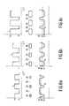
- Figs. 6a, 6b and 6c show the intensity variation I, the corresponding information pattern of effects 58 and intermediate areas 59, and the read signal Vl in the case that the write intensity Is is too low, optimum and too high respectively.
- the read signals Vl vary between a maximum level A1 and a minimum level A2.
- the level DC represents the value of the d.c. level in the read signal Vl.
- the d.c. level DC of the read signal Vl is substantially centred between the levels A1 and A2 if the write intensity has the optimum value. If the write intensity is too low the d.c. level DC will be situated above the middle between the levels A1 and A2, while in the case that the write level is too high the d.c. level DC will be situated below the middle between the levels A1 and A2.
- an optimum write intensity can be obtained by adjusting the write intensity Is to a value for which the d.c. level DC is situated substantially in the middle between the levels A1 and A2.
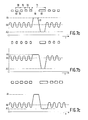
- an information pattern is recorded for the purpose of determining the optimum intensity, which pattern comprises a plurality of subpatterns 70 each comprising a short effect 58 and a short intermediate area 59, recorded by means of a write signal having a 50% duty cycle.
- the information pattern further comprises a second subpattern 71 comprising a comparatively long effect 58 and a comparatively long intermediate area 59, also recorded with the aid of a write signal having a 50% duty cycle.
- the number of subpatterns 70 is selected to be substantially larger than the number of subpatterns 71.
- Fig. 7a further shows the read signal Vl obtained in the case of reading with the aid of an optical read device.
- the dimensions of the subpatterns 70 are selected in such a way that the amplitude of the signal components in the read signal Vl corresponding to said subpatterns 70 is substantially smaller than the amplitude of the signal components corresponding to the subpatterns 71. This can be achieved by selecting the dimensions of the subpatterns 70 in such a way that only the 1st harmonic of this pattern is situated below the optical cut-off frequency of the optical scanning device.
- the dimensions of the subpattern 71 are selected in such a way that at least the 1st and the 2nd harmonic of this pattern are situated below said optical cut-off frequency.
- the d.c. level DC in the read signal Vl is dictated mainly by the signal components corresponding to the subpatterns 70.
- the difference between the maximum value A1 and the minimum value A2 of the read signal Vl is dictated exclusively by the value corresponding to the subpattern 71.
- the d.c. level DC in the case of the method illustrated in Fig. 4 will also be far more susceptible to write level variations than in the case of the method illustrated in Fig. 6, where the amplitude of the read signal Vl is the same for all the subpatterns occurring in the information pattern. All this means that the optimum write power can be determined far more accurately by means of the method illustrated in Fig. 7a.
- Figs. 7b and 7c Similar information patterns are shown in Figs. 7b and 7c, which have been recorded at a write level which is too low and which is too high respectively.
- the d.c. level DC in the case of the optimum write intensity is again substantially centred between the maximum signal value (A1) and the minimum signal value (A2) in the signal Vl, while in the case of a write level which is too low or too high the d.c. level DC is situated above and below the centre respectively.
- a subpattern which is also very suitable is a pattern corresponding to an EFM signal in conformity with the CD standard.
- Such a pattern comprises areas of a length corresponding to at least 3 bits (I3 effect) and at the most 11 bits (I11 effect).
- I3 effect Approximately one third of all the effects in such an EFM pattern are I3 effects, whereas only 4 % of all the effects are I11 effects.
- the dimensions of the I3 effects are such that only the fundamental of these effects is situated below the optical cut-off frequency of the optical read system. Of the I11 effects at least the 1st, the 2nd and the 3rd harmonic are situated below the optical cut-off frequency.
- Fig. 8 shows an example of the analysis circuit 10 by means of which an analysis signal Va can be derived from the read signal Vl to indicate the extent to which the d.c. level DC deviates from the level corresponding to the optimum write intensity.
- the analysis circuit 10 in Fig. 8 comprises a low-pass filter 80 for determining the d.c. level DC in the read signal Vl.
- the analysis circuit 10 further comprises a positive-peak detector 81 for determining the maximum value A1 in the read signal Vl and a negative-peak detector 82 for determining the minimum value A2 in the read signal Vl.
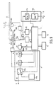
- Fig. 9 shows in detail an embodiment of an information recording device for recording standard CD signals.
- the recording device shown comprises drive means in the form of a motor 100 and a turntable 101 for rotating a radiation-sensitive record carrier 1 about the axis 2, which record carrier is of a type on which address information has been recorded as a track modulation of the servo track.
- the track modulation may be a track wobble, the frequency of the wobble being modulated in conformity with a position information signal comprising absolute time codes ATIP.
- the read/write head 3 is of a customary type comprising a semiconductor laser for generating a radiation beam 107a whose intensity is adjustable by means of the driver circuit 8.
- the radiation beam 107 is aimed at the servo track of the record carrier 1.
- the beam 107a is then reflected partly from the record carrier 1, the reflected beam being modulated in conformity with the track wobble and, if an information pattern has been recorded, also in conformity with the information pattern.
- the reflected beam is directed towards a radiation-sensitive detector 108a, which generates the read signal Vl corresponding to the beam modulation.
- the signal Vl comprises a component produced by the track wobble and having a frequency of approximately 22 kHz at the nominal constant linear scanning velocity.
- a motor control circuit 108 for controlling the motor 100 By means of a motor control circuit 108 for controlling the motor 100 the motor speed is controlled so as to maintain the frequency of the component produced by the track wobble in the read signal Vl at substantially 22 kHz, so that a constant linear scanning velocity is realised.
- the address detection circuit 15 is of a type which derives the time codes ATIP from the component produced in the read signal Vl by the track wobble and applies these codes to the control unit 5.
- the read signal Vl is applied to an amplifier circuit 111 having a high-pass characteristic in order to reject the signal components produced in the read signal Vl by the track wobble.
- the read signal Vl from which the low frequency components have thus been removed, is applied to the analysis circuit 10.
- the signal processing circuit 7 further comprises a customary CIRC encoding circuit 112, to which the signal Vi to be recorded can be applied via a switch 11a which is controlled by the control unit 5.
- the CIRC encoding circuit 112 is arranged in series with a customary EFM modulator 113 which adds subcode information to the main information received from the CIRC encoder 112 and subsequently converts this information into an EFM modulated signal.
- the EFM modulator is coupled to the control unit 5.
- the EFM modulator 113 has its output connected to the driver circuit 8.
- the driver circuit 8 is of a controllable type.
- the driver circuit 8 sets the intensity of the generated beam 107a to a constant low intensity Il or the driver circuit 8 switches the intensity of the beam between the low level Il and the write level Is in conformity with the EFM modulated signal received from the EFM modulator 113.
- the write level Is can be adjusted by the control unit 5.
- the recording device shown in Fig. 9 comprises a signal generator 11, which comprises the switch 11a and the signal generator 11b.
- the signal generator 11b generates a random digital signal or a signal corresponding to the digital signal value zero (digital silence).
- the signal generated by the signal generator 11b is applied to the CIRC encoding circuit 112 via the switch 11a.
- the switch 11a is of a customary type, which depending on the control signal received from the control unit 5 transfers either the signal Vi to be recorded or the output signal of the signal generator 11b.
- the read circuit 9 comprises an EFM demodulator 114 of a customary type, which reconverts the EFM words in the read signal Vl into information words and which separates the subcode information from the main information.
- the subcode information in particular the subcode Q information, is applied to the microcomputer 110.
- the main information is applied to a CIRC decoder 115 of a customary type, which recovers the original information signal Vi from the main information received from the EFM demodulator 114.
- the control unit 5 is loaded with suitable program.
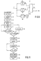
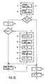
- Fig. 10 shows a flow chart of such a program, which substantially corresponds to the flow chart shown in Fig. 2 but in which a number of steps have been divided into substeps.
- the record carrier identification code if any, is read in the step A11.
- Two substeps B1 and B2 are then carried out.
- the record carrier area with the start address TIA of the identification area IA is located under control of the control unit 5. Once this area is reached the control unit recovers the record carrier identification code from the subcode Q signal received from the read circuit 9. Subsequently, it is ascertained in the step A12 whether the adjustment data, specifically the optimum write-intensity setting Iopt, for this code has been stored in the memory 12. If this is the case the write intensity is set to the value Iopt under control of the control unit 5 in the step A13.
- the optimum value Iopt for the write intensity is derived in A14 during a calibration program to be described in more detail hereinafter with reference to Fig. 11.
- the step A14 it is ascertained in the step A15 whether the record carrier already has a record carrier identification code. If this is the case, the adjustment value together with the record carrier identification code is stored in the memory 12 in the step A16 and subsequently the program proceeds with the step A13.
- the record carrier is provided with a record carrier identification code in the step A17.
- the substeps B3 through B7 are carried out.
- a new record carrier identification code is generated by means of the random code generator 13.
- the identification area IA having the address TIA is located. Once this area is reached recording is started in the step B5 by setting the read/write head to the write mode.
- the new record carrier identification code is converted to the format required for the subcode Q-channel and is applied to the EFM modulator 113.
- a plurality of subcode Q-frames with the record carrier identification code for example 10, are recorded in succession, because this improves the reliability of reading the record carrier identification code at a subsequent instant.
- the read/write head 3 is again set to the read mode in the step B7 and the program proceeds with the step A16.
- Fig. 11 is a flowchart of the calibration program carried out in the step A14.
- a test area within the area PCA is selected in which the test information patterns can be recorded. The manner in which this can be effected is described in detail in inter alia the afore-mentioned NL-A-8901591 (PHN 12.994).
- the selected area is located under control of the control unit 5. Once this area is reached the write intensity Is is set to the initial value Io in the step S4.
- the value of Io for the relevant record carrier is prerecorded on the record carrier in a manner as described in Patent Application NL-A-8901145 (PHN 12.925). This value can then be read prior to the set-up cycle.
- the signal generator 11b is connected to the CIRC encoding circuit 112 by means of the controllable switch 11a, so that an EFM modulated test signal, determined by the output signal of the signal generator, is generated by the EFM modulator 113.
- the read/write head 3 is set to the write mode, which results in a test information pattern corresponding to an EFM signal being recorded.
- the absolute time code ATIP detected by the address detection circuit 15 is read by the control unit 5.
- the step S6 it is ascertained whether this absolute time code has changed relative to the previous read-out. If this is not the case, the step S5 is repeated.
- step S7 If it has changed, it is tested in the step S7 whether the absolute time code being read indicates the end of the test area. If this is not the case the step S8 is performed, in which the write intensity Is is incremented by a small step ⁇ I, after which the program proceeds with the step S5. If in the step S7 it is found that the end of the test area is reached the step S9 is performed, in which the read/write head 3 is again set to the read mode. In the step S10 the beginning of the test area just described is located again and is read. In the step S11 the analysis signal Va is read by the control unit 5. In the step S12 it is checked whether the value of the analysis signal Va corresponds to the optimum write intensity. If this is not the case, the program proceeds with the step S11.
- the absolute time code detected by the address detection circuit 15 is read out in the step S13.
- the optimum write intensity corresponding to the absolute time code read in the step S13 is computed. This is possible, for example, by determining the difference between the absolute time code last read and the time code corresponding to the beginning of the test area. By means of this difference it is possible to determine by how many steps ⁇ I the initial value Io has been incremented before the absolute time code ATIP last read was reached during the recording of the test information pattern. This number of steps and the initial value Io define the optimum write intensity Iopt.
Abstract
Description
- The invention relates to an information recording device comprising write means for providing the record carrier with information patterns, means for determining record carrier dependent adjustment data, adjustment means for adjusting the write means in conformity with the determined adjustment data, the means for determining the adjustment data being adapted to record information patterns for different settings of the write means and to determine, on the basis of the recorded information pattern, the adjustment data in accordance with a predetermined criterion.
- Such a device is known from US 4,631,713. In the known device the adjustment data is determined every time that the record carrier is introduced into the device. A drawback of the known device is that it takes a comparatively long time to determine the optimum adjustment.
- It is an object of the invention to provide a device as defined in the opening paragraph, which requires less time to determine the optimum adjustment of the write means.
- According to the invention this object is achieved in that the information recording device further comprises storage means for storing in a memory the determined adjustment data together with identification data indicative of the combination of the recording device and the record carrier for which the adjustment data has been determined, and detection means for detecting, after insertion of a record carrier into the information recording device, whether adjustment data for the relevant combination of a record carrier and information recording device has been stored in the memory, the adjustment means being adapted to adjust the write means in conformity with the adjustment data in the case that adjustment data for the said combination has been stored. The invention is based on inter alia the recognition of the fact that the optimum adjustment of the write means is found to change hardly in the course of time.
- As a result of the storage of the adjustment data and the identification data in a memory the adjustment has to be determined only once for a specific combination of a record carrier and an information recording device, so that the time required for determining the adjustment data is also minimised.
- It is possible to assign a device identification code to the information recording device and to provide the recording device with means for recording the device identification code together with the adjustment data on the record carrier. However, it is preferred to use an embodiment of the information recording device, which is characterized in that the storage means are adapted to store in a memory of the information recording device the determined adjustment data together with the record carrier identification code indicative of the record carrier for which the data has been determined, the recording device comprising read means for reading a record carrier identification code which may be present on the record carrier, the detection means being adapted to determine whether adjustment data for the record carrier identification thus read has been stored in the memory of the device. The last-mentioned embodiment has the advantage that the adjustment data occupies a minimal space on the record carrier. This is particularly so if the same record carrier is used in more than one recording device. In the last-mentioned embodiment it is then adequate to record only one record carrier identification on the record carrier, while in the case that a device identification is recorded for each of the information recording devices used a device identification and the adjustment data should be recorded on the record carrier. In principle, the record carrier identification can be applied during manufacture of the record carrier. In the case of optical record carriers this is possible in that the master employed in the fabrication of the record carriers is provided with an identification pattern. The problem which then occurs is that a complete series of the record carriers has the same record carrier identification code. Since the recording parameters of the record carriers may vary within one series of record carriers it is possible that if two record carriers of the same series are employed in the same information recording device the information patterns are not recorded in an optimum manner for both record carriers.
- An embodiment of the information recording device which mitigates this drawback is characterized in that the device comprises means for providing the record carrier with a record carrier identification. Preferably, the information recording device then comprises a random-code generator for generating the record carrier identification to be recorded. This minimizes the likelihood of the same record carrier identification being recorded in the case of mass or series produced information recording devices. Thus the likelihood of a non-optimum adjustment when the same record carrier is used in different information recording devices is minimized.
- The device in accordance with the invention is particularly suitable for use in apparatus in which the linear velocity with which the record carrier is scanned during the recording of the information patterns is constant. In that case the changes in the recording conditions are minimal, so that a previously determined optimum adjustment of the write means need not be adapted.
- However, the invention is not limited to device with a constant linear scanning velocity during recording. It can also be employed in systems with variable scanning velocities, in which the scanning velocity has no influence or a predictable influence on the adjustment of the write means.
- Further embodiments of the recording device and the advantages thereof will now be described in more detail with reference to Figs. 1 to 11, in which
- Figs. 1 and 9 show embodiments of the information recording device in accordance with the invention;
- Figs. 2 and 10 are flow charts of programs carried out by a control unit in the devices shown in Figs. 1 and 9;
- Fig. 3 shows a suitable format for recording a record carrier identification code;
- Fig. 4 shows a suitable position for recording the record carrier identification code;
- Figs. 5, 6 and 7 by way of illustration show a possible calibration procedure for determining an optimum adjustment;
- Fig. 8 shows an example of an analysis circuit for use in the information recording device, and
- Fig. 11 is a flow chart for a calibration program which can be carried out by the control unit for the information recording device.
- Fig. 1 by way of example shows an embodiment of an information recording device in accordance with the invention. The present embodiment is a recording device by means of which information can be recorded on a
record carrier 1, for example an optical record carrier, which is rotated about anaxis 2. The information recording device comprises acustomary write head 3, arranged opposite the rotatingrecord carrier 1. By means of a customary positioning system, for example in the form of amotor 4 and aspindle 5, the read-writehead 3 can be moved in a radial direction relative to therecord carrier 1 under control of acustomary control unit 6, which comprises for example a microprocessor. - An information signal Vi to be recorded can be applied to a
signal processing circuit 7 via aninput 6. Thesignal processing circuit 7 is of a customary type, which converts the applied input signal into a recording signal Vop of a suitable recording format, for example a CD format. The recording signal Vop is applied to adriver circuit 8 of a customary type, which converts the recording signal Vop into a drive signal Vs for the read/writehead 3 in such a way that an information pattern corresponding to the recording signal Vop is recorded on the record carrier. For the purpose of reading the recorded information patterns the read/writehead 3 has an output for supplying a read signal Vl which is representative of the information pattern being read. The read signal Vl is applied to aread circuit 9 for recovering the information represented by the read signal. Thedriver circuit 8 is of an adjustable type, enabling one or more of the parameters with which the quality of the recorded information pattern can be influenced to be adjusted. When an optical read/write head is used by which an information pattern of optically detectable effects is formed by means of a radiation beam, the intensity of the radiation beam is an important parameter which largely dictates the quality of the information pattern. If the read/write head is a magnetic or magneto-optical write head which generates a magnetic field for the purpose of forming an information pattern in the form of magnetic effects (domains), the field strength of the generated magnetic field may be an important adjustment parameter. - If the information pattern is formed by means of write pulses the pulse width may be an important adjustment parameter. It is to be noted that the above-mentioned adjustment parameters are only few examples of the large number of adjustment parameters which are possible. In this respect reference is made in particular to NL-A- 9000150 (PHN 13.217), in which the adjustment parameter is a reference value for the speed with which the effects are formed. During the formation of the effects the intensity of the write beam is controlled to maintain the speed with which the effects are formed at the adjusted reference value.
- For determining the optimum adjustment of the
driver circuit 8 the device comprises ananalysis circuit 10, which derives from the read signal an analysis signal which is indicative of the quality of the information pattern being read. The optimum adjustment can be determined by forming test information patterns on therecord carrier 1 for different settings of the driver circuit and by selecting, on the basis of the analysis signal Va, that setting for which the analysis signal indicates an optimum quality. In principle, the information signal Vi may be employed for writing the test information pattern. However, it is also possible to employ atest signal generator 11 for this purpose, which may then be included, for example, in thesignal processing circuit 7. The optimum adjustment is determined under control of thecontrol unit 15, which for this purpose is coupled to theanalysis circuit 10, to thedriver circuit 8, and to thetest signal generator 11, if present, which control unit is loaded with a suitable program or comprises a suitable hardware circuit. Preferably, the optimum adjustment is determined in a calibration procedure, which is carried out after a record carrier has been inserted in the information recording device for the first time. The optimum adjustment data and the identification data which are indicative of the combination of a record carrier and recording device are subsequently stored. When the same record carrier is reinserted into the recording device the stored adjustment data can then be employed again, so that it is not necessary to carry out a new calibration procedure. This saves a considerable amount of time. - With respect to the storage of adjustment data it is to be noted that this adjustment data may be stored both on the record carrier itself and in a
memory 12 of the information recording device. When the adjustment data is stored on the record carrier identification data in the form of a device identification can be recorded together with the adjustment data. After a record carrier has been loaded into the information recording device it is then possible on the basis of the device identiciation recorded on the record carrier to detect unambiguously whether the adjustment data has already been determined for the relevant combination of a record carrier and an information recording device. If this is the case a calibration procedure is not necessary and thedriver circuit 8 can be adjusted in conformity with the adjustment data associated with the device identification. - Although in the above method of storing the adjustment data it is always possible to determine unambiguously whether the adjustment data has already been determined in a previous calibration procedure, this method has the disadvantage that the amount of space occupied on the record carrier by the adjustment data and the device identification codes may be substantial. This is particularly so if the same record carrier is employed in a large number of information recording devices. Indeed, in that case every information recording device will record its own adjustment data and device identification code on the record carrier.
- This drawback is mitigated if the record carrier is provided with a record carrier identification code and the identification data in the form of a record carrier identification code and the associated adjustment data are stored in the information recording device.
- In principle, the record carrier can be provided with the record carrier identification code during manufacture. This has the drawback that it often allows only those methods to be used in which always complete series of record carriers are provided with the same record carrier identification code. If in such a case two or more record carriers are employed in the same information recording device it is not unlikely that on account of the usual differences between the recording parameters of the record carriers the
write circuit 8 is not optimised for all the record carriers of the same series. Therefore, it is preferred to apply the record carrier identification code by means of the first information recording device in which it is used. Preferably, the record carrier identification code to be recorded is a random generated code. This minimises the likelihood that the same record carrier identification code is generated for different record carriers when two or more information recording devices of the same make and type are used. - To determine the random record carrier identification code the information recording device may be provided with a
random code generator 13. Therandom code generator 13 may comprise, for example, a noise source whose output signal is sampled and is digitised by means of a digital-to-analog converter. The random code generator may alternatively comprise a cyclic counter which counts the pulses of a high-frequency clock signal. However, other code generators are also possible, such as for example one of a type realised by means of software included in the software of the control unit 51. - Fig. 2 is a flow chart of a program for determining and storing the adjustment data in the case that the record carrier is provided with a record carrier identification and that the identification data and the associated adjustment data are stored in the
memory 12 of the information recording device. - The flow chart comprises a step A11 in which a record carrier identification which may be present on the record carrier is read under control of the
control unit 5. Under control of thecontrol unit 5 the read/write head 3 is then moved to a record carrier area intended for recording the record carrier identification code. In a step A12 it is ascertained whether adjustment data has been stored in thememory 12 for the record carrier identification read. If this is so a step A13 is carried out, in which thedriver circuit 8 is adjusted in conformity with the adjustment data associated with the record carrier identification code read. In the absence of adjustment data a calibration procedure is carried out in a step A14, to determine the optimum setting. An example of the calibration procedure will be described in more detail hereinafter. - After the calibration procedure has been carried out it is ascertained in a step A15 whether the
record carrier 1 has already been provided with a record carrier identification code. If this is the case, the record carrier identification code together with the adjustment data is stored in thememory 12 in a step A16, for example in a table in which a plurality of combinations of record carrier identification codes and adjustment data can be stored. Subsequently, the program proceeds with the step A13 described above. If during the step A15 it is found that therecord carrier 1 has not yet been provided with a record carrier identification code a new record carrier identification code is generated by means of therandom code generator 13 in a step A17. If desired, it is also checked whether this code occurs in the table in order to prevent the same record carrier identification code being assigned to two record carriers. The newly generated record carrier identification code is recorded on the record carrier at a location from which it can be retrieved. When a record carrier provided with address information is used it is possible to employ for this purpose a record carrier part having a predetermined address. However, alternatively this information may be recorded at a predetermined location on the record carrier, for example at a predetermined distance from the centre of rotation of the record carrier. In the case that the information is recorded at a location having a predetermined address, the information recording device should comprise anaddress detection circuit 15 for determining the addresses, which circuit recovers the address information from the read signal Vl and supplies the recovered address information to thecontrol unit 5. During recording of the record carrier identification code the read/write head 3 is positioned under control of thecontrol unit 5 in a customary manner, for example on the basis of the received address information, opposite to the area intended for recording the record carrier identification code and, subsequently, the read/write head 3 is set to a write mode and an information signal Vident, which is representative of the record carrier identification code, is applied to an input of thesignal processing circuit 7. Thesignal processing circuit 7 then converts the signal Vident into a recording signal suitable for recording and a corresponding identification pattern is recorded on therecord carrier 1. - After termination of the step A17 the program proceeds with the steps A16 and A13 already discussed. After the step A13 recording of the signal Vi can be started under optimum conditions in a step A18.
- In the foregoing an embodiment of the information recording device has been disclosed which is suitable for recording information on a disc-shaped record carrier. However, it is to be noted that the scope of the invention is not limited to such recording devices. It may also be applied to recording devices in which the information is recorded on a tape, for example a magnetic tape.
- Moreover, it is to be noted that the calibration procedure to be used for determining the optimum adjustment data depends on the recording principle employed in the information recording device. For a number of different calibration procedures suitable for use within the scope of the present invention reference is made to Netherlands Patent Applications NL-A-8901345 (PHQ 89.016), NL-A-8901591 (PHN 12.994), and NL-A-900150 (PHN 13.217), herewith incorporated by reference. The optimum location for recording the record carrier identification code and the form in which the identification code is recorded depend strongly on the type of the record carrier used and on the format to which the information signal is converted for the purpose of recording. In a device for recording a standard CD signal it is preferred to insert the record carrier identification code to be recorded in the subcode Q-channel of the CD signal. In that case the record carrier identification code can be extracted simply from the read signal by means of a subcode detector as customarily used in CD players. This is in contradistinction to the case in which the record carrier identification code is included in the main channel of the CD signal. In the last-mentioned case determining the record carrier identification code requires additional hardware. A suitable format for the record carrier identlfication code in the subcode Q-channel is shown in Fig. 3. In this format a plurality of
bits 30 in aframe 31 of the subcode Q-channel serve to indicate the record carrier identification code. A suitable record carrier for recording standard CD signals is described in NL-A-8901591 and NL-A-8900766 (PHN 12.994 and PHN 12.887). Such a record carrier has a spiral servotrack which is intended for information recording. The servotrack has a track modulation, for example a frequency-modulated track wobble, representing addresses in the form of absolute time codes ATIP. The servotrack is divided into a plurality of areas as indicated in Fig. 4. In this Figure the spiral track is shown diagrammatically as a straight line and bears thereference numeral 40. Theservotrack 40 comprises an area PA (Program Area) intended for recording information signals, such as for example digitised audio signals, an area LI (Lead In) intended for recording a table of contents ("TOC") as prescribed by the CD standard, an area PMA which is intended for recording a temporarly table of contents as described in NL-A-8900766 (PHN 12.887), and an area PCA intended for recording test information patterns for the purpose of determining the optimum adjustment data. The start addresses of the areas PCA, PMA, LI and PA are designated TPCA, TPMA, TLI and TPA respectively. In the layout of theservotrack 40 as shown in Fig. 4 particularly the areas PCA and PMA are suitable for recording the record carrier identification code. By way of example twosuitable areas 41 and 41a are indicated in Fig. 4. Hereinafter the area 41 will be referred to as the identification area IA and the address of this area will be designated TIA. Theareas 41 and 41a, which are situated outside the areas LI and PA, have a format as prescribed by the CD standard for "read-only" discs. This has the advantage that the read-out of a record carrier of the inscribable type on which a standard CD signal has been recorded is not disturbed by the presence of the record carrier identification code if reading is performed by a read device intended for reading "Compact Discs" of the "read-only" type. - Hereinafter an embodiment of the recording device in accordance with the invention will be described, by way of example, for recording information on the optical record carrier described above. First of all, a suitable method of determining the optimum adjustment data will be explained. An optically readable record carrier may be provided with an information pattern comprising effects having varying reflection properties by scanning the record carrier with a radiation beam whose intensity I is switched between a low level Il, for which there are no changes in reflection, and a high write level Is, which produces a change in reflection in the scanned part of the record carrier. Fig. 5 gives an example of such an intensity variation and the associated pattern of
effects 58 having changed reflection properties andintermediate areas 59 having unchanged properties. The information pattern ofeffects 58 andintermediate areas 59 can be read by scanning the pattern with a read beam of a constant intensity, which is low enough to preclude a detectable change in optical properties. During the scanning process the read beam reflected from the record carrier is modulated in conformity with the information pattern being scanned. The modulation of the read beam can be detected in a customary manner by means of a radiation-sensitive detector, which generates a read signal Vl which is indicative of the beam modulation. The read signal Vl is also shown in Fig. 5. The read signal Vl is reconverted into a bivalent signal by comparison of the read signal with a reference level Vref. For a reliable conversion it is desirable that the points where the read signal Vl intersects the reference level are well-defined, in other words, the "jitter" in the read signal Vl should be minimal. As is known, jitter of the read signal Vl in optical recording is minimal if the information pattern is symmetrical, i.e. if the average length of theeffects 58 is equal to the average length of theintermediate areas 59. The problem which then arises is that the length of theeffects 58 strongly depends on the write intensity Is. If the write intensity is too high theeffects 58 will be too long and if the write intensity is too low theeffects 58 will be too short. Therefore, an accurate adjustment of the write intensity is required. A method of determining the optimum write intensity will be described in more detail with reference to Fig. 6. Figs. 6a, 6b and 6c show the intensity variation I, the corresponding information pattern ofeffects 58 andintermediate areas 59, and the read signal Vl in the case that the write intensity Is is too low, optimum and too high respectively. - In Fig. 6 the read signals Vl vary between a maximum level A1 and a minimum level A2. The level DC represents the value of the d.c. level in the read signal Vl. As will be apparent from Fig. 6 the d.c. level DC of the read signal Vl is substantially centred between the levels A1 and A2 if the write intensity has the optimum value. If the write intensity is too low the d.c. level DC will be situated above the middle between the levels A1 and A2, while in the case that the write level is too high the d.c. level DC will be situated below the middle between the levels A1 and A2. Thus, an optimum write intensity can be obtained by adjusting the write intensity Is to a value for which the d.c. level DC is situated substantially in the middle between the levels A1 and A2.
- An improvement of the above method of determining the optimum intensity will be described with reference to Fig. 7a. In accordance with this method an information pattern is recorded for the purpose of determining the optimum intensity, which pattern comprises a plurality of
subpatterns 70 each comprising ashort effect 58 and a shortintermediate area 59, recorded by means of a write signal having a 50% duty cycle. The information pattern further comprises asecond subpattern 71 comprising a comparativelylong effect 58 and a comparatively longintermediate area 59, also recorded with the aid of a write signal having a 50% duty cycle. The number ofsubpatterns 70 is selected to be substantially larger than the number ofsubpatterns 71. Fig. 7a further shows the read signal Vl obtained in the case of reading with the aid of an optical read device. - The dimensions of the
subpatterns 70 are selected in such a way that the amplitude of the signal components in the read signal Vl corresponding to said subpatterns 70 is substantially smaller than the amplitude of the signal components corresponding to thesubpatterns 71. This can be achieved by selecting the dimensions of thesubpatterns 70 in such a way that only the 1st harmonic of this pattern is situated below the optical cut-off frequency of the optical scanning device. The dimensions of thesubpattern 71 are selected in such a way that at least the 1st and the 2nd harmonic of this pattern are situated below said optical cut-off frequency. The d.c. level DC in the read signal Vl is dictated mainly by the signal components corresponding to thesubpatterns 70. The difference between the maximum value A1 and the minimum value A2 of the read signal Vl is dictated exclusively by the value corresponding to thesubpattern 71. As a change in write power Is has a substantially greater influence on the ratio between the lengths of theeffects 58 and theintermediate areas 59 of thesubpatterns 70 than on the ratio between said lengths for thesubpatterns 71, the d.c. level DC in the case of the method illustrated in Fig. 4 will also be far more susceptible to write level variations than in the case of the method illustrated in Fig. 6, where the amplitude of the read signal Vl is the same for all the subpatterns occurring in the information pattern. All this means that the optimum write power can be determined far more accurately by means of the method illustrated in Fig. 7a. - In addition to the information pattern shown in Fig. 7a, which has been recorded with an optimum write intensity, similar information patterns are shown in Figs. 7b and 7c, which have been recorded at a write level which is too low and which is too high respectively. As will be apparent from Fig. 7, the d.c. level DC in the case of the optimum write intensity is again substantially centred between the maximum signal value (A1) and the minimum signal value (A2) in the signal Vl, while in the case of a write level which is too low or too high the d.c. level DC is situated above and below the centre respectively. The information pattern shown in Fig. 7 is only one of the possible information patterns comprising a comparatively large number of subpatterns comprising short effects and intermediate areas and a comparatively small number of sub patterns comprising long effects and intermediate areas. A subpattern which is also very suitable is a pattern corresponding to an EFM signal in conformity with the CD standard. Such a pattern comprises areas of a length corresponding to at least 3 bits (I3 effect) and at the most 11 bits (I11 effect). Approximately one third of all the effects in such an EFM pattern are I3 effects, whereas only 4 % of all the effects are I11 effects. The dimensions of the I3 effects are such that only the fundamental of these effects is situated below the optical cut-off frequency of the optical read system. Of the I11 effects at least the 1st, the 2nd and the 3rd harmonic are situated below the optical cut-off frequency.
- Fig. 8 shows an example of the
analysis circuit 10 by means of which an analysis signal Va can be derived from the read signal Vl to indicate the extent to which the d.c. level DC deviates from the level corresponding to the optimum write intensity. Theanalysis circuit 10 in Fig. 8 comprises a low-pass filter 80 for determining the d.c. level DC in the read signal Vl. Theanalysis circuit 10 further comprises a positive-peak detector 81 for determining the maximum value A1 in the read signal Vl and a negative-peak detector 82 for determining the minimum value A2 in the read signal Vl. The output signals of thepeak detectors adder circuit 83, while the output signal of the low-pass filter 80, after amplification to twice its value, is applied to an inverting input of theadder circuit 83, so that the output signal of the adder circuit, which signal constitutes the analysis signal Va, complies with Va = A1 + A2 - 2DC and consequently indicates the extent to which the signal value DC deviates from the mean value of the maximum signal value A1 and the minimum signal value A1. - For other suitable examples of analysis circuits reference is made to NL-A-8901591 (PHN 12.994).
- Fig. 9 shows in detail an embodiment of an information recording device for recording standard CD signals. In this Figure elements corresponding to the elements already described bear the same reference numerals. The recording device shown comprises drive means in the form of a
motor 100 and aturntable 101 for rotating a radiation-sensitive record carrier 1 about theaxis 2, which record carrier is of a type on which address information has been recorded as a track modulation of the servo track. The track modulation may be a track wobble, the frequency of the wobble being modulated in conformity with a position information signal comprising absolute time codes ATIP. The read/write head 3 is of a customary type comprising a semiconductor laser for generating aradiation beam 107a whose intensity is adjustable by means of thedriver circuit 8. In known manner the radiation beam 107 is aimed at the servo track of therecord carrier 1. Thebeam 107a is then reflected partly from therecord carrier 1, the reflected beam being modulated in conformity with the track wobble and, if an information pattern has been recorded, also in conformity with the information pattern. The reflected beam is directed towards a radiation-sensitive detector 108a, which generates the read signal Vl corresponding to the beam modulation. The signal Vl comprises a component produced by the track wobble and having a frequency of approximately 22 kHz at the nominal constant linear scanning velocity. By means of amotor control circuit 108 for controlling themotor 100 the motor speed is controlled so as to maintain the frequency of the component produced by the track wobble in the read signal Vl at substantially 22 kHz, so that a constant linear scanning velocity is realised. Theaddress detection circuit 15 is of a type which derives the time codes ATIP from the component produced in the read signal Vl by the track wobble and applies these codes to thecontrol unit 5. Moreover, the read signal Vl is applied to anamplifier circuit 111 having a high-pass characteristic in order to reject the signal components produced in the read signal Vl by the track wobble. The read signal Vl, from which the low frequency components have thus been removed, is applied to theanalysis circuit 10. Thesignal processing circuit 7 further comprises a customaryCIRC encoding circuit 112, to which the signal Vi to be recorded can be applied via aswitch 11a which is controlled by thecontrol unit 5. TheCIRC encoding circuit 112 is arranged in series with acustomary EFM modulator 113 which adds subcode information to the main information received from theCIRC encoder 112 and subsequently converts this information into an EFM modulated signal. For the subcode information the EFM modulator is coupled to thecontrol unit 5. The EFM modulator 113 has its output connected to thedriver circuit 8. Thedriver circuit 8 is of a controllable type. Depending on the control signals received from thecontrol unit 5 thedriver circuit 8 sets the intensity of the generatedbeam 107a to a constant low intensity Il or thedriver circuit 8 switches the intensity of the beam between the low level Il and the write level Is in conformity with the EFM modulated signal received from theEFM modulator 113. Moreover, the write level Is can be adjusted by thecontrol unit 5. For the purpose of recording the test information pattern the recording device shown in Fig. 9 comprises asignal generator 11, which comprises theswitch 11a and thesignal generator 11b. Thesignal generator 11b generates a random digital signal or a signal corresponding to the digital signal value zero (digital silence). The signal generated by thesignal generator 11b is applied to theCIRC encoding circuit 112 via theswitch 11a. Theswitch 11a is of a customary type, which depending on the control signal received from thecontrol unit 5 transfers either the signal Vi to be recorded or the output signal of thesignal generator 11b. - The
read circuit 9 comprises anEFM demodulator 114 of a customary type, which reconverts the EFM words in the read signal Vl into information words and which separates the subcode information from the main information. The subcode information, in particular the subcode Q information, is applied to the microcomputer 110. The main information is applied to aCIRC decoder 115 of a customary type, which recovers the original information signal Vi from the main information received from theEFM demodulator 114. For determining the write intensity setting thecontrol unit 5 is loaded with suitable program. Fig. 10 shows a flow chart of such a program, which substantially corresponds to the flow chart shown in Fig. 2 but in which a number of steps have been divided into substeps. The record carrier identification code, if any, is read in the step A11. Two substeps B1 and B2 are then carried out. In the step B1 the record carrier area with the start address TIA of the identification area IA is located under control of thecontrol unit 5. Once this area is reached the control unit recovers the record carrier identification code from the subcode Q signal received from the readcircuit 9. Subsequently, it is ascertained in the step A12 whether the adjustment data, specifically the optimum write-intensity setting Iopt, for this code has been stored in thememory 12. If this is the case the write intensity is set to the value Iopt under control of thecontrol unit 5 in the step A13. If not, the optimum value Iopt for the write intensity is derived in A14 during a calibration program to be described in more detail hereinafter with reference to Fig. 11. After the step A14 it is ascertained in the step A15 whether the record carrier already has a record carrier identification code. If this is the case, the adjustment value together with the record carrier identification code is stored in thememory 12 in the step A16 and subsequently the program proceeds with the step A13. - In the other case the record carrier is provided with a record carrier identification code in the step A17. During this step the substeps B3 through B7 are carried out. In the step B3 a new record carrier identification code is generated by means of the
random code generator 13. In the step B4 the identification area IA having the address TIA is located. Once this area is reached recording is started in the step B5 by setting the read/write head to the write mode. In the step B6 the new record carrier identification code is converted to the format required for the subcode Q-channel and is applied to theEFM modulator 113. Preferably, a plurality of subcode Q-frames with the record carrier identification code, for example 10, are recorded in succession, because this improves the reliability of reading the record carrier identification code at a subsequent instant. After said number of subcode Q frames with the record carrier identification code has been recorded the read/write head 3 is again set to the read mode in the step B7 and the program proceeds with the step A16. - Fig. 11 is a flowchart of the calibration program carried out in the step A14. In the step S1 a test area within the area PCA is selected in which the test information patterns can be recorded. The manner in which this can be effected is described in detail in inter alia the afore-mentioned NL-A-8901591 (PHN 12.994). In the step S2 the selected area is located under control of the
control unit 5. Once this area is reached the write intensity Is is set to the initial value Io in the step S4. Preferably, the value of Io for the relevant record carrier is prerecorded on the record carrier in a manner as described in Patent Application NL-A-8901145 (PHN 12.925). This value can then be read prior to the set-up cycle. Moreover, under control of thecontrol unit 5 thesignal generator 11b is connected to theCIRC encoding circuit 112 by means of thecontrollable switch 11a, so that an EFM modulated test signal, determined by the output signal of the signal generator, is generated by theEFM modulator 113. Finally, in the step 54 the read/write head 3 is set to the write mode, which results in a test information pattern corresponding to an EFM signal being recorded. In the step S5 the absolute time code ATIP detected by theaddress detection circuit 15 is read by thecontrol unit 5. In the step S6 it is ascertained whether this absolute time code has changed relative to the previous read-out. If this is not the case, the step S5 is repeated. If it has changed, it is tested in the step S7 whether the absolute time code being read indicates the end of the test area. If this is not the case the step S8 is performed, in which the write intensity Is is incremented by a small step ΔI, after which the program proceeds with the step S5. If in the step S7 it is found that the end of the test area is reached the step S9 is performed, in which the read/write head 3 is again set to the read mode. In the step S10 the beginning of the test area just described is located again and is read. In the step S11 the analysis signal Va is read by thecontrol unit 5. In the step S12 it is checked whether the value of the analysis signal Va corresponds to the optimum write intensity. If this is not the case, the program proceeds with the step S11. In the other case the absolute time code detected by theaddress detection circuit 15 is read out in the step S13. Subsequently, in the step S15, the optimum write intensity corresponding to the absolute time code read in the step S13 is computed. This is possible, for example, by determining the difference between the absolute time code last read and the time code corresponding to the beginning of the test area. By means of this difference it is possible to determine by how many steps ΔI the initial value Io has been incremented before the absolute time code ATIP last read was reached during the recording of the test information pattern. This number of steps and the initial value Io define the optimum write intensity Iopt. - It is to be noted that the calibration procedure described herein is only one of the many procedures possible for optical record carriers of this type. Another very suitable calibration procedure for record carriers of this type is described in, for example, NL-A-900150 (PHN 13.217).
Claims (5)
- An information recording device comprising write means for providing the record carrier with information patterns, means for determining record carrier dependent adjustment data, adjustment means for adjusting the write means in conformity with the determined adjustment data, the means for determining the adjustment data being adapted to record information patterns for different settings of the write means and to determine, on the basis of the recorded information pattern, the adjustment data in accordance with a predetermined criterion, characterized in that the information recording device further comprises storage means for storing in a memory the determined adjustment data together with identification data indicative of the combination of the recording device and the record carrier for which the adjustment data has been determined, and detection means for detecting, after insertion of a record carrier into the information recording device, whether adjustment data for the relevant combination of a record carrier and information recording device has been stored in the memory, the adjustment means being adapted to adjust the write means in conformity with the adjustment data in the case that adjustment data for the said combination has been stored.
- An information recording device as claimed in Claim 1, characterized in that the storage means are adapted to store in a memory of the information recording device the determined adjustment data together with the record carrier identification code indicative of the record carrier for which the data has been determined, the recording device comprising read means for reading a record carrier identification code which may be present on the record carrier, the detection means being adapted to determine whether adjustment data for the record carrier identification thus read has been stored in the memory of the device.
- An information recording device as claimed in Claim 1, characterized in that the device comprises means for providing the record carrier with a record carrier identification.
- An information recording device as claimed in Claim 3, characterized in that the recording device comprises a random-code generator for generating the record carrier identification code.
- An information recording device as claimed in any one of the preceding Claims, characterized in that the write means comprise means for scanning the record carrier with a constant linear velocity by means of a write head, which write head, for the purpose of recording the information patterns, comprises means for realizing a detectable change in the record carrier area being scanned.
Applications Claiming Priority (2)
| Application Number | Priority Date | Filing Date | Title |
|---|---|---|---|
| NL9000327 | 1990-02-12 | ||
| NL9000327A NL9000327A (en) | 1990-02-12 | 1990-02-12 | INFORMATION RECORDING DEVICE. |
Publications (2)
| Publication Number | Publication Date |
|---|---|
| EP0442566A1 true EP0442566A1 (en) | 1991-08-21 |
| EP0442566B1 EP0442566B1 (en) | 1995-12-13 |
Family
ID=19856577
Family Applications (1)
| Application Number | Title | Priority Date | Filing Date |
|---|---|---|---|
| EP91200257A Expired - Lifetime EP0442566B1 (en) | 1990-02-12 | 1991-02-08 | Information recording device |
Country Status (7)
| Country | Link |
|---|---|
| US (1) | US5072435A (en) |
| EP (1) | EP0442566B1 (en) |
| JP (1) | JP3238158B2 (en) |
| KR (1) | KR100221461B1 (en) |
| DE (1) | DE69115304T2 (en) |
| HK (1) | HK109496A (en) |
| NL (1) | NL9000327A (en) |
Cited By (18)
| Publication number | Priority date | Publication date | Assignee | Title |
|---|---|---|---|---|
| US5363361A (en) * | 1992-03-04 | 1994-11-08 | U.S. Philips Corporation | Information recording device having variable data transfer rates and verification of recording quality |
| EP0712120A1 (en) * | 1994-05-31 | 1996-05-15 | Sony Corporation | Data recorder |
| US5548572A (en) * | 1995-03-31 | 1996-08-20 | International Business Machines Corporation | Spare and calibration sector management for optical WORM media |
| EP0744738A1 (en) * | 1995-05-23 | 1996-11-27 | Sharp Kabushiki Kaisha | Optical disk device |
| EP0751509A2 (en) * | 1995-06-26 | 1997-01-02 | Pioneer Electronic Corporation | Optical recording medium and method for setting power of laser beam |
| WO1997013244A1 (en) * | 1995-09-29 | 1997-04-10 | Philips Electronics N.V. | Information carrier and recording device for recording an information carrier |
| EP0817193A2 (en) * | 1996-06-28 | 1998-01-07 | International Business Machines Corporation | Calibration apparatus for information storage system |
| EP0984441A1 (en) * | 1998-09-14 | 2000-03-08 | Matsushita Electric Industrial Co., Ltd. | Recording medium, recording apparatus and recording method |
| EP1026669A2 (en) * | 1999-02-02 | 2000-08-09 | Matsushita Electric Industrial Co., Ltd. | Optical recording medium and recording/reproduction method and apparatus therefor |
| WO2000067257A2 (en) * | 1999-04-28 | 2000-11-09 | Matsushita Electric Industrial Co., Ltd. | Optical disk, optical disk recording and reproducing apparatus, method for recording, reproducing and deleting data on optical disk, and information processing system |
| EP1130583A1 (en) * | 2000-03-03 | 2001-09-05 | Ricoh Company, Ltd. | Optical recording method and apparatus, and optical storage medium |
| EP1170744A2 (en) * | 2000-07-05 | 2002-01-09 | Thomson Licensing S.A. | Method for quickly configuring an optical recording and reproducing apparatus and an apparatus using the same |
| EP1189211A1 (en) * | 2000-08-14 | 2002-03-20 | Ricoh Company, Ltd. | Method for optically recording information and computer-readable recording medium for causing a computer to optically record information |
| US6552982B1 (en) | 1999-03-08 | 2003-04-22 | Matsushita Electric Industrial Co., Ltd. | Information recording medium, information recording and reproduction method, and information recording and reproduction apparatus |
| WO2004025639A1 (en) * | 2002-09-11 | 2004-03-25 | Koninklijke Philips Electronics N.V. | Multilayer optical disc having a recording stack type indicator |
| WO2005114661A1 (en) * | 2004-05-18 | 2005-12-01 | Koninklijke Philips Electronics N.V. | Optical disc drive for writing on blank recordable or rewritable media |
| EP1607942A1 (en) * | 2003-03-25 | 2005-12-21 | Ricoh Company, Ltd. | Optical information recording device, optical information recording medium, optical information recording method, program, and computer-readable information storage medium |
| US7023772B2 (en) | 2002-08-23 | 2006-04-04 | Sony Corporation | Laser power setting method and optical recording device |
Families Citing this family (33)
| Publication number | Priority date | Publication date | Assignee | Title |
|---|---|---|---|---|
| US5303217A (en) * | 1989-06-23 | 1994-04-12 | U.S. Philips Corporation | Optical recording device wherein recording beam intensity is set in accordance with an optimum value of the DC component of a recorded signal |
| JP2915098B2 (en) * | 1990-06-29 | 1999-07-05 | 株式会社日立製作所 | Digital signal recording / reproducing device |
| US5418770A (en) * | 1990-06-29 | 1995-05-23 | Hitachi, Ltd. | Method of and apparatus for correcting edge interval of pit in optical recording/read-out apparatus |
| JP2809835B2 (en) * | 1990-07-30 | 1998-10-15 | 松下電器産業株式会社 | Optical disk device and optical disk |
| JP2896925B2 (en) * | 1990-09-04 | 1999-05-31 | 三菱電機株式会社 | Optical disk recording device |
| JPH04139666A (en) * | 1990-09-30 | 1992-05-13 | Ricoh Co Ltd | Semiconductor integrated circuit and semiconductor device for signal processing for direct-read-after-write type optical disk |
| US5220549A (en) * | 1991-02-19 | 1993-06-15 | Olympus Optical Co., Ltd. | Information recording/reproducing apparatus which includes pickup having memory for storing specific characteristics thereof |
| US5878019A (en) * | 1991-04-02 | 1999-03-02 | U.S. Philips Corporation | Record carrier having at least two information volumes |
| DE69226116T2 (en) * | 1991-04-02 | 1999-02-18 | Philips Electronics Nv | Record carrier, readout device for reading the record carrier, and method and recording device for recording information on a record carrier |
| US5341356A (en) * | 1991-04-02 | 1994-08-23 | U.S. Philips Corporation | Method and device for recording information volumes in a track of a record carrier, and a device for reading the record carrier |
| JP3141429B2 (en) * | 1991-04-11 | 2001-03-05 | ソニー株式会社 | Video adjustment device for recording and playback devices |
| JP3050336B2 (en) * | 1991-07-05 | 2000-06-12 | パイオニア株式会社 | Recording method on write-once optical disc and optical disc recording apparatus |
| JP3433811B2 (en) * | 1992-09-30 | 2003-08-04 | ソニー株式会社 | Disk duplication device |
| JP3212415B2 (en) * | 1993-04-26 | 2001-09-25 | 株式会社リコー | Control method of optical recording device |
| US5444686A (en) * | 1993-09-28 | 1995-08-22 | Dunlavy; John H. | Method and apparatus for correcting distortion in compact disc recording and playback system |
| JP3248186B2 (en) * | 1994-08-31 | 2002-01-21 | ソニー株式会社 | Still image system |
| US5696756A (en) * | 1995-04-14 | 1997-12-09 | Kabushiki Kaishia Toshiba | Optical disk having an evaluation pattern for evaluating the optical disk |
| JP3284296B2 (en) * | 1995-06-27 | 2002-05-20 | 富士通株式会社 | Optical recording medium and recording / reproducing method thereof |
| KR100601598B1 (en) * | 1998-06-15 | 2006-07-14 | 삼성전자주식회사 | Recording medium storing write protection information and write protecting method |
| US6765853B1 (en) | 1998-06-15 | 2004-07-20 | Samsung Electronics Co., Ltd. | Recording medium for storing write protection information and write protection method thereof |
| US6925040B1 (en) * | 1998-08-04 | 2005-08-02 | Hitachi, Ltd. | Information recording method, information recording medium and information recording apparatus |
| KR100288783B1 (en) * | 1998-09-18 | 2001-05-02 | 구자홍 | Detecting and storing recording optical power of optical recording medium, apparatus and method for controlling recording optical power using same |
| EP1082721B1 (en) * | 1999-03-23 | 2003-07-30 | Koninklijke Philips Electronics N.V. | Method of decoding a stream of channel bits of a signal relating to a binary channel signal into a stream of source bits of a signal relating to a binary source signal |
| IL139771A0 (en) * | 1999-03-23 | 2002-02-10 | Moninklijke Philips Electronic | Information carrier, device for encoding, method for encoding, device for decoding and method for decoding |
| AU5566200A (en) * | 1999-06-22 | 2001-01-09 | Matsushita Electric Industrial Co., Ltd. | Optical disk, optical disk device, and reproducing method for optical disk |
| KR100350983B1 (en) * | 2000-02-03 | 2002-08-28 | 삼성전자 주식회사 | Laser diode driver, initializing method of optical recording/reproducing apparatus therefor, and driving method of laser diode driver |
| US6611927B1 (en) * | 2000-05-25 | 2003-08-26 | Oak Technology, Inc. | Apparatus and method for ideal value estimation in an optical PRML read channel |
| JP4114767B2 (en) | 2000-10-13 | 2008-07-09 | パイオニア株式会社 | Information recording apparatus and information recording method |
| JP2002245625A (en) * | 2001-02-19 | 2002-08-30 | Pioneer Electronic Corp | Recording medium, information recording device and method, information recording medium and recording program |
| EP1629493A2 (en) * | 2003-05-19 | 2006-03-01 | Koninklijke Philips Electronics N.V. | Disc drive apparatus, and method for timing recalibration in a disc drive apparatus |
| KR20060018227A (en) * | 2003-05-19 | 2006-02-28 | 코닌클리케 필립스 일렉트로닉스 엔.브이. | Disc drive apparatus, and method for timing recalibration in a disc drive apparatus |
| US20060044980A1 (en) * | 2003-06-03 | 2006-03-02 | Toshiyuki Fukushima | Recording/reproduction device, recording /reproduction method, recording/reproduction system, program thereof, and recording medium |
| CN1833275A (en) * | 2003-09-19 | 2006-09-13 | 株式会社理光 | Information recording apparatus and an information recording system |
Citations (2)
| Publication number | Priority date | Publication date | Assignee | Title |
|---|---|---|---|---|
| EP0126682A1 (en) * | 1983-05-20 | 1984-11-28 | Thomson-Csf | Method and apparatus for calibrating the optical power applied to an optical disc for data recording |
| EP0265849A2 (en) * | 1986-10-24 | 1988-05-04 | Hitachi, Ltd. | Optical recording/reproducing method and apparatus |
Family Cites Families (3)
| Publication number | Priority date | Publication date | Assignee | Title |
|---|---|---|---|---|
| JPS6050666A (en) * | 1983-08-29 | 1985-03-20 | Hitachi Ltd | Recording control system |
| US4717971A (en) * | 1984-08-24 | 1988-01-05 | Eastman Kodak Company | Partitioned editing method for a collection of video still pictures |
| US4943861A (en) * | 1987-03-03 | 1990-07-24 | Analogic Corporation | Apparatus and method for exposing photosensitive recording media with digital image data |
-
1990
- 1990-02-12 NL NL9000327A patent/NL9000327A/en not_active Application Discontinuation
- 1990-06-21 US US07/542,287 patent/US5072435A/en not_active Expired - Lifetime
-
1991
- 1991-02-08 DE DE69115304T patent/DE69115304T2/en not_active Expired - Lifetime
- 1991-02-08 EP EP91200257A patent/EP0442566B1/en not_active Expired - Lifetime
- 1991-02-09 KR KR1019910002202A patent/KR100221461B1/en not_active IP Right Cessation
- 1991-02-12 JP JP03904891A patent/JP3238158B2/en not_active Expired - Lifetime
-
1996
- 1996-06-27 HK HK109496A patent/HK109496A/en not_active IP Right Cessation
Patent Citations (2)
| Publication number | Priority date | Publication date | Assignee | Title |
|---|---|---|---|---|
| EP0126682A1 (en) * | 1983-05-20 | 1984-11-28 | Thomson-Csf | Method and apparatus for calibrating the optical power applied to an optical disc for data recording |
| EP0265849A2 (en) * | 1986-10-24 | 1988-05-04 | Hitachi, Ltd. | Optical recording/reproducing method and apparatus |
Cited By (61)
| Publication number | Priority date | Publication date | Assignee | Title |
|---|---|---|---|---|
| US5363361A (en) * | 1992-03-04 | 1994-11-08 | U.S. Philips Corporation | Information recording device having variable data transfer rates and verification of recording quality |
| EP0712120A4 (en) * | 1994-05-31 | 1997-11-12 | Sony Corp | Data recorder |
| EP0712120A1 (en) * | 1994-05-31 | 1996-05-15 | Sony Corporation | Data recorder |
| EP1158500A1 (en) * | 1994-05-31 | 2001-11-28 | Sony Corporation | Data recording apparatus |
| US5548572A (en) * | 1995-03-31 | 1996-08-20 | International Business Machines Corporation | Spare and calibration sector management for optical WORM media |
| WO1996030902A1 (en) * | 1995-03-31 | 1996-10-03 | International Business Machines Corporation | Spare and calibration sector management for optical worm media |
| EP0744738A1 (en) * | 1995-05-23 | 1996-11-27 | Sharp Kabushiki Kaisha | Optical disk device |
| US5696742A (en) * | 1995-05-23 | 1997-12-09 | Sharp Kabushiki Kaisha | Optical disk device for reproducing address information from wobbled groove |
| EP0751509A2 (en) * | 1995-06-26 | 1997-01-02 | Pioneer Electronic Corporation | Optical recording medium and method for setting power of laser beam |
| EP0751509A3 (en) * | 1995-06-26 | 1998-05-20 | Pioneer Electronic Corporation | Optical recording medium and method for setting power of laser beam |
| EP1150287A3 (en) * | 1995-06-26 | 2001-11-21 | Pioneer Electronic Corporation | Optical recording medium and method for setting power of laser beam |
| US5898655A (en) * | 1995-06-26 | 1999-04-27 | Pioneer Electronic Corporation | Optical recording medium and method for setting power of laser beam |
| EP1150287A2 (en) * | 1995-06-26 | 2001-10-31 | Pioneer Electronic Corporation | Optical recording medium and method for setting power of laser beam |
| USRE38602E1 (en) | 1995-06-26 | 2004-09-28 | Pioneer Corporation | Optical recording medium and method for setting power of laser beam |
| BE1009677A3 (en) * | 1995-09-29 | 1997-06-03 | Philips Electronics Nv | INFORMATION CARRIER AND DEVICE FOR DESCRIBING AN INFORMATION CARRIER. |
| WO1997013244A1 (en) * | 1995-09-29 | 1997-04-10 | Philips Electronics N.V. | Information carrier and recording device for recording an information carrier |
| EP0817193A2 (en) * | 1996-06-28 | 1998-01-07 | International Business Machines Corporation | Calibration apparatus for information storage system |
| EP0817193A3 (en) * | 1996-06-28 | 1999-02-17 | International Business Machines Corporation | Calibration apparatus for information storage system |
| US5978335A (en) * | 1996-06-28 | 1999-11-02 | Ibm | Integrated calibration apparatus for a multi-mode information storage system |
| US6157609A (en) * | 1998-09-14 | 2000-12-05 | Matsushita Electric Industrial Co., Ltd. | Recording medium, recording apparatus and recording method |
| WO2000016323A1 (en) * | 1998-09-14 | 2000-03-23 | Matsushita Electric Industrial Co., Ltd. | Recording medium, recording apparatus and recording method |
| US6359846B1 (en) | 1998-09-14 | 2002-03-19 | Matsushita Electric Industrial Co., Ltd. | Recording medium recording apparatus and recording method |
| US6349081B1 (en) | 1998-09-14 | 2002-02-19 | Matsushita Electric Industrial Co., Ltd. | Recording medium, recording apparatus and recording method |
| EP0987697A1 (en) * | 1998-09-14 | 2000-03-22 | Matsushita Electric Industrial Co., Ltd. | Recording medium, recording apparatus and recording method |
| EP0984441A1 (en) * | 1998-09-14 | 2000-03-08 | Matsushita Electric Industrial Co., Ltd. | Recording medium, recording apparatus and recording method |
| EP0987698A1 (en) * | 1998-09-14 | 2000-03-22 | Matsushita Electric Industrial Co., Ltd. | Recording medium, recording apparatus and recording method |
| WO2000046798A1 (en) * | 1999-02-02 | 2000-08-10 | Matsushita Electric Industrial Co., Ltd. | Optical recording medium and recording / reproduction method and apparatus therefor |
| EP1026671A1 (en) * | 1999-02-02 | 2000-08-09 | Matsushita Electric Industrial Co., Ltd. | Optical recording medium and recording/reproduction method and apparatus therefor |
| US6411575B1 (en) | 1999-02-02 | 2002-06-25 | Matsushita Electric Industrial Co., Ltd. | Optical recording medium having an area for recording a plurality of recording/reproduction conditions to be used in recording/reproduction apparatuses and recording/reproduction method and apparatus therefor |
| EP1031967A1 (en) * | 1999-02-02 | 2000-08-30 | Matsushita Electric Industrial Co., Ltd. | Optical recording medium and recording/reproduction method and apparatus therefor |
| EP1026670A3 (en) * | 1999-02-02 | 2000-08-30 | Matsushita Electric Industrial Co., Ltd. | Optical recording medium and recording/reproduction method and apparatus therefor |
| EP1026669A3 (en) * | 1999-02-02 | 2000-08-30 | Matsushita Electric Industrial Co., Ltd. | Optical recording medium and recording/reproduction method and apparatus therefor |
| US6469964B1 (en) | 1999-02-02 | 2002-10-22 | Matsushita Electric Industrial Co., Ltd. | Optical recording medium and recording/reproduction method and apparatus therefor |
| CN1306484C (en) * | 1999-02-02 | 2007-03-21 | 松下电器产业株式会社 | Optical recording medium and recording/reproduction method and apparatus therefor |
| US6414922B1 (en) | 1999-02-02 | 2002-07-02 | Matsushita Electric Industrial Co., Ltd. | Optical recording medium having an area for recording a plurality of recording/reproduction conditions to be used in recording/reproduction apparatuses and recording/reproduction method and apparatus therefore |
| US6535468B2 (en) | 1999-02-02 | 2003-03-18 | Matsushita Electric Industrial Co., Ltd. | Optical recording medium having an area for recording a plurality of recording/reproduction conditions to be used in recording/reproduction apparatuses and recording/reproduction method and apparatus therefor |
| EP1026670A2 (en) * | 1999-02-02 | 2000-08-09 | Matsushita Electric Industrial Co., Ltd. | Optical recording medium and recording/reproduction method and apparatus therefor |
| EP1026669A2 (en) * | 1999-02-02 | 2000-08-09 | Matsushita Electric Industrial Co., Ltd. | Optical recording medium and recording/reproduction method and apparatus therefor |
| US6552982B1 (en) | 1999-03-08 | 2003-04-22 | Matsushita Electric Industrial Co., Ltd. | Information recording medium, information recording and reproduction method, and information recording and reproduction apparatus |
| US6940795B2 (en) | 1999-03-08 | 2005-09-06 | Matsushita Electric Industrial Co., Ltd. | Information recording medium, information recording and reproduction method, and information recording and reproduction apparatus |
| WO2000067257A3 (en) * | 1999-04-28 | 2001-04-26 | Matsushita Electric Ind Co Ltd | Optical disk, optical disk recording and reproducing apparatus, method for recording, reproducing and deleting data on optical disk, and information processing system |
| US6938162B1 (en) | 1999-04-28 | 2005-08-30 | Matsushita Electric Industrial Co., Ltd. | Optical disk, optical disk recording and reproducing apparatus, method for recording, reproducing and deleting data on optical disk, and information processing system |
| WO2000067257A2 (en) * | 1999-04-28 | 2000-11-09 | Matsushita Electric Industrial Co., Ltd. | Optical disk, optical disk recording and reproducing apparatus, method for recording, reproducing and deleting data on optical disk, and information processing system |
| EP1058254A2 (en) * | 1999-04-28 | 2000-12-06 | Matsushita Electric Industrial Co., Ltd. | Optical disk, optical disk recording and reproducing apparatus, method for recording, reproducing and deleting data on optical disk, and information processing system |
| EP1058254A3 (en) * | 1999-04-28 | 2001-11-21 | Matsushita Electric Industrial Co., Ltd. | Optical disk, optical disk recording and reproducing apparatus, method for recording, reproducing and deleting data on optical disk, and information processing system |
| EP1130583A1 (en) * | 2000-03-03 | 2001-09-05 | Ricoh Company, Ltd. | Optical recording method and apparatus, and optical storage medium |
| US6631109B2 (en) | 2000-03-03 | 2003-10-07 | Ricoh Company, Ltd. | Optical recording method and apparatus, and optical storage medium |
| US7799181B2 (en) | 2000-03-03 | 2010-09-21 | Ricoh Company, Ltd. | Method for controlling a multi-pulse record waveform at high velocity in a phase change optical medium |
| US7382706B2 (en) | 2000-03-03 | 2008-06-03 | Ricoh Company, Ltd. | Method for controlling a multi-pulse record waveform at high velocity in a phase change optical medium |
| US7193950B2 (en) | 2000-03-03 | 2007-03-20 | Ricoh Company, Ltd. | Method for controlling a multi-pulse record waveform at high velocity in a phase change optical medium |
| US7206271B2 (en) | 2000-03-03 | 2007-04-17 | Ricoh Company, Ltd. | Method for controlling a multi-pulse record waveform at high velocity in a phase change optical medium |
| EP1170744A2 (en) * | 2000-07-05 | 2002-01-09 | Thomson Licensing S.A. | Method for quickly configuring an optical recording and reproducing apparatus and an apparatus using the same |
| EP1170744A3 (en) * | 2000-07-05 | 2003-02-05 | Thomson Licensing S.A. | Method for quickly configuring an optical recording and reproducing apparatus and an apparatus using the same |
| EP1189211A1 (en) * | 2000-08-14 | 2002-03-20 | Ricoh Company, Ltd. | Method for optically recording information and computer-readable recording medium for causing a computer to optically record information |
| US7254102B2 (en) | 2000-08-14 | 2007-08-07 | Ricoh Company, Ltd. | Method for optically recording information according to a strategy and computer-readable recording medium for causing a computer to optically record information according to a strategy |
| US7023772B2 (en) | 2002-08-23 | 2006-04-04 | Sony Corporation | Laser power setting method and optical recording device |
| WO2004025639A1 (en) * | 2002-09-11 | 2004-03-25 | Koninklijke Philips Electronics N.V. | Multilayer optical disc having a recording stack type indicator |
| US7764591B2 (en) | 2002-09-11 | 2010-07-27 | Koninklijke Philips Electronics N.V. | Multilayer optical disc having a recording stack type indicator |
| EP1607942A1 (en) * | 2003-03-25 | 2005-12-21 | Ricoh Company, Ltd. | Optical information recording device, optical information recording medium, optical information recording method, program, and computer-readable information storage medium |
| EP1607942A4 (en) * | 2003-03-25 | 2008-08-20 | Ricoh Kk | Optical information recording device, optical information recording medium, optical information recording method, program, and computer-readable information storage medium |
| WO2005114661A1 (en) * | 2004-05-18 | 2005-12-01 | Koninklijke Philips Electronics N.V. | Optical disc drive for writing on blank recordable or rewritable media |
Also Published As
| Publication number | Publication date |
|---|---|
| HK109496A (en) | 1996-07-05 |
| DE69115304T2 (en) | 1996-07-11 |
| EP0442566B1 (en) | 1995-12-13 |
| JPH04214208A (en) | 1992-08-05 |
| US5072435A (en) | 1991-12-10 |
| JP3238158B2 (en) | 2001-12-10 |
| KR910015982A (en) | 1991-09-30 |
| DE69115304D1 (en) | 1996-01-25 |
| NL9000327A (en) | 1991-09-02 |
| KR100221461B1 (en) | 1999-10-01 |
Similar Documents
| Publication | Publication Date | Title |
|---|---|---|
| EP0442566B1 (en) | Information recording device | |
| EP0404249B1 (en) | Method of and device for adjusting recording parameters | |
| US5896353A (en) | Servo control apparatus for controlling position of device | |
| EP0642128B1 (en) | Recordable optical disk | |
| US5303217A (en) | Optical recording device wherein recording beam intensity is set in accordance with an optimum value of the DC component of a recorded signal | |
| US4853915A (en) | Optical recording/reproducing method and apparatus for optical disk medium having unique control parameters | |
| EP0397238A1 (en) | Information recording system, and recording device and record carrier for use in such an information recording system | |
| EP0888614B1 (en) | Optical recording medium | |
| US7263052B2 (en) | Method for generating a binary signal having a predetermined spectral shape | |
| EP0709842B1 (en) | Recording and reproduction of data | |
| EP0404251B1 (en) | Recording device for recording an optically detectable information pattern on a record carrier | |
| US7123552B2 (en) | Wobble signal detecting circuit for optical disc system | |
| US6246650B1 (en) | Method and apparatus for high speed data reproduction | |
| EP0511875B1 (en) | Information recording and reproducing apparatus | |
| EP0642122B1 (en) | Method and system for recording information on an optical disk | |
| JP3916675B2 (en) | Optical recording method and apparatus using the method | |
| US7123563B2 (en) | Optical recording method and apparatus using this method | |
| KR100265115B1 (en) | A data detecting circuit of header signal in a optical disc recording and reproducing device and the method therefor | |
| JPH0896396A (en) | Optical recording and reproducing device | |
| US5453971A (en) | Recorded area detection to prevent information overwriting | |
| JP3795555B2 (en) | Optical disk device | |
| JP2002216379A (en) | Optical disk apparatus and method of calculating sled servo compensation amount | |
| WO1998025266A1 (en) | Optical recording medium | |
| JPH11213412A (en) | Amplitude adjusting device for tracking error signal, and optical disk device | |
| JPH0896385A (en) | Optical disk device |
Legal Events
| Date | Code | Title | Description |
|---|---|---|---|
| PUAI | Public reference made under article 153(3) epc to a published international application that has entered the european phase |
Free format text: ORIGINAL CODE: 0009012 |
|
| AK | Designated contracting states |
Kind code of ref document: A1 Designated state(s): BE DE FR GB |
|
| 17P | Request for examination filed |
Effective date: 19920221 |
|
| 17Q | First examination report despatched |
Effective date: 19940905 |
|
| GRAA | (expected) grant |
Free format text: ORIGINAL CODE: 0009210 |
|
| AK | Designated contracting states |
Kind code of ref document: B1 Designated state(s): BE DE FR GB |
|
| PG25 | Lapsed in a contracting state [announced via postgrant information from national office to epo] |
Ref country code: BE Effective date: 19951213 |
|
| REF | Corresponds to: |
Ref document number: 69115304 Country of ref document: DE Date of ref document: 19960125 |
|
| ET | Fr: translation filed | ||
| PLBE | No opposition filed within time limit |
Free format text: ORIGINAL CODE: 0009261 |
|
| STAA | Information on the status of an ep patent application or granted ep patent |
Free format text: STATUS: NO OPPOSITION FILED WITHIN TIME LIMIT |
|
| 26N | No opposition filed | ||
| REG | Reference to a national code |
Ref country code: FR Ref legal event code: CD |
|
| REG | Reference to a national code |
Ref country code: GB Ref legal event code: IF02 |
|
| PGFP | Annual fee paid to national office [announced via postgrant information from national office to epo] |
Ref country code: FR Payment date: 20100311 Year of fee payment: 20 |
|
| PGFP | Annual fee paid to national office [announced via postgrant information from national office to epo] |
Ref country code: GB Payment date: 20100226 Year of fee payment: 20 |
|
| PGFP | Annual fee paid to national office [announced via postgrant information from national office to epo] |
Ref country code: DE Payment date: 20100430 Year of fee payment: 20 |
|
| REG | Reference to a national code |
Ref country code: DE Ref legal event code: R071 Ref document number: 69115304 Country of ref document: DE |
|
| REG | Reference to a national code |
Ref country code: GB Ref legal event code: PE20 Expiry date: 20110207 |
|
| PG25 | Lapsed in a contracting state [announced via postgrant information from national office to epo] |
Ref country code: GB Free format text: LAPSE BECAUSE OF EXPIRATION OF PROTECTION Effective date: 20110207 |
|
| PG25 | Lapsed in a contracting state [announced via postgrant information from national office to epo] |
Ref country code: DE Free format text: LAPSE BECAUSE OF EXPIRATION OF PROTECTION Effective date: 20110208 |