EP0443185A2 - Method and device for assisting a motorist when changing lanes - Google Patents
Method and device for assisting a motorist when changing lanes Download PDFInfo
- Publication number
- EP0443185A2 EP0443185A2 EP90125132A EP90125132A EP0443185A2 EP 0443185 A2 EP0443185 A2 EP 0443185A2 EP 90125132 A EP90125132 A EP 90125132A EP 90125132 A EP90125132 A EP 90125132A EP 0443185 A2 EP0443185 A2 EP 0443185A2
- Authority
- EP
- European Patent Office
- Prior art keywords
- distance
- evaluation
- vehicle
- motor vehicle
- traffic
- Prior art date
- Legal status (The legal status is an assumption and is not a legal conclusion. Google has not performed a legal analysis and makes no representation as to the accuracy of the status listed.)
- Granted
Links
- 238000000034 method Methods 0.000 title claims abstract description 25
- 238000011156 evaluation Methods 0.000 claims abstract description 26
- 230000001133 acceleration Effects 0.000 claims abstract description 20
- 238000005259 measurement Methods 0.000 claims abstract description 15
- 238000012544 monitoring process Methods 0.000 claims description 3
- 230000035484 reaction time Effects 0.000 claims description 3
- 230000007423 decrease Effects 0.000 claims description 2
- 230000008859 change Effects 0.000 abstract description 26
- 230000008901 benefit Effects 0.000 abstract description 3
- 230000008569 process Effects 0.000 description 10
- 238000001514 detection method Methods 0.000 description 5
- 230000005540 biological transmission Effects 0.000 description 3
- 238000010521 absorption reaction Methods 0.000 description 2
- 238000006243 chemical reaction Methods 0.000 description 2
- 238000012937 correction Methods 0.000 description 2
- 238000013461 design Methods 0.000 description 2
- 239000013307 optical fiber Substances 0.000 description 2
- 238000002310 reflectometry Methods 0.000 description 2
- 239000007921 spray Substances 0.000 description 2
- 230000006978 adaptation Effects 0.000 description 1
- 230000015572 biosynthetic process Effects 0.000 description 1
- 230000008094 contradictory effect Effects 0.000 description 1
- 230000003247 decreasing effect Effects 0.000 description 1
- 230000000694 effects Effects 0.000 description 1
- 238000013209 evaluation strategy Methods 0.000 description 1
- 230000004438 eyesight Effects 0.000 description 1
- 230000004313 glare Effects 0.000 description 1
- 230000004886 head movement Effects 0.000 description 1
- 238000011835 investigation Methods 0.000 description 1
- 230000003387 muscular Effects 0.000 description 1
- 230000009467 reduction Effects 0.000 description 1
- 230000004044 response Effects 0.000 description 1
- 238000012502 risk assessment Methods 0.000 description 1
- 230000011664 signaling Effects 0.000 description 1
- 230000009897 systematic effect Effects 0.000 description 1
- 230000001960 triggered effect Effects 0.000 description 1
- 230000000007 visual effect Effects 0.000 description 1
Images


Classifications
-
- B—PERFORMING OPERATIONS; TRANSPORTING
- B60—VEHICLES IN GENERAL
- B60Q—ARRANGEMENT OF SIGNALLING OR LIGHTING DEVICES, THE MOUNTING OR SUPPORTING THEREOF OR CIRCUITS THEREFOR, FOR VEHICLES IN GENERAL
- B60Q1/00—Arrangement of optical signalling or lighting devices, the mounting or supporting thereof or circuits therefor
- B60Q1/26—Arrangement of optical signalling or lighting devices, the mounting or supporting thereof or circuits therefor the devices being primarily intended to indicate the vehicle, or parts thereof, or to give signals, to other traffic
- B60Q1/2661—Arrangement of optical signalling or lighting devices, the mounting or supporting thereof or circuits therefor the devices being primarily intended to indicate the vehicle, or parts thereof, or to give signals, to other traffic mounted on parts having other functions
- B60Q1/2665—Arrangement of optical signalling or lighting devices, the mounting or supporting thereof or circuits therefor the devices being primarily intended to indicate the vehicle, or parts thereof, or to give signals, to other traffic mounted on parts having other functions on rear-view mirrors
-
- B—PERFORMING OPERATIONS; TRANSPORTING
- B60—VEHICLES IN GENERAL
- B60Q—ARRANGEMENT OF SIGNALLING OR LIGHTING DEVICES, THE MOUNTING OR SUPPORTING THEREOF OR CIRCUITS THEREFOR, FOR VEHICLES IN GENERAL
- B60Q9/00—Arrangement or adaptation of signal devices not provided for in one of main groups B60Q1/00 - B60Q7/00, e.g. haptic signalling
- B60Q9/008—Arrangement or adaptation of signal devices not provided for in one of main groups B60Q1/00 - B60Q7/00, e.g. haptic signalling for anti-collision purposes
-
- B—PERFORMING OPERATIONS; TRANSPORTING
- B60—VEHICLES IN GENERAL
- B60W—CONJOINT CONTROL OF VEHICLE SUB-UNITS OF DIFFERENT TYPE OR DIFFERENT FUNCTION; CONTROL SYSTEMS SPECIALLY ADAPTED FOR HYBRID VEHICLES; ROAD VEHICLE DRIVE CONTROL SYSTEMS FOR PURPOSES NOT RELATED TO THE CONTROL OF A PARTICULAR SUB-UNIT
- B60W30/00—Purposes of road vehicle drive control systems not related to the control of a particular sub-unit, e.g. of systems using conjoint control of vehicle sub-units, or advanced driver assistance systems for ensuring comfort, stability and safety or drive control systems for propelling or retarding the vehicle
- B60W30/18—Propelling the vehicle
- B60W30/18009—Propelling the vehicle related to particular drive situations
- B60W30/18163—Lane change; Overtaking manoeuvres
-
- G—PHYSICS
- G01—MEASURING; TESTING
- G01S—RADIO DIRECTION-FINDING; RADIO NAVIGATION; DETERMINING DISTANCE OR VELOCITY BY USE OF RADIO WAVES; LOCATING OR PRESENCE-DETECTING BY USE OF THE REFLECTION OR RERADIATION OF RADIO WAVES; ANALOGOUS ARRANGEMENTS USING OTHER WAVES
- G01S13/00—Systems using the reflection or reradiation of radio waves, e.g. radar systems; Analogous systems using reflection or reradiation of waves whose nature or wavelength is irrelevant or unspecified
- G01S13/88—Radar or analogous systems specially adapted for specific applications
- G01S13/93—Radar or analogous systems specially adapted for specific applications for anti-collision purposes
- G01S13/931—Radar or analogous systems specially adapted for specific applications for anti-collision purposes of land vehicles
-
- G—PHYSICS
- G01—MEASURING; TESTING
- G01S—RADIO DIRECTION-FINDING; RADIO NAVIGATION; DETERMINING DISTANCE OR VELOCITY BY USE OF RADIO WAVES; LOCATING OR PRESENCE-DETECTING BY USE OF THE REFLECTION OR RERADIATION OF RADIO WAVES; ANALOGOUS ARRANGEMENTS USING OTHER WAVES
- G01S17/00—Systems using the reflection or reradiation of electromagnetic waves other than radio waves, e.g. lidar systems
- G01S17/88—Lidar systems specially adapted for specific applications
- G01S17/93—Lidar systems specially adapted for specific applications for anti-collision purposes
- G01S17/931—Lidar systems specially adapted for specific applications for anti-collision purposes of land vehicles
-
- G—PHYSICS
- G01—MEASURING; TESTING
- G01S—RADIO DIRECTION-FINDING; RADIO NAVIGATION; DETERMINING DISTANCE OR VELOCITY BY USE OF RADIO WAVES; LOCATING OR PRESENCE-DETECTING BY USE OF THE REFLECTION OR RERADIATION OF RADIO WAVES; ANALOGOUS ARRANGEMENTS USING OTHER WAVES
- G01S13/00—Systems using the reflection or reradiation of radio waves, e.g. radar systems; Analogous systems using reflection or reradiation of waves whose nature or wavelength is irrelevant or unspecified
- G01S13/88—Radar or analogous systems specially adapted for specific applications
- G01S13/93—Radar or analogous systems specially adapted for specific applications for anti-collision purposes
- G01S13/931—Radar or analogous systems specially adapted for specific applications for anti-collision purposes of land vehicles
- G01S2013/9315—Monitoring blind spots
-
- G—PHYSICS
- G01—MEASURING; TESTING
- G01S—RADIO DIRECTION-FINDING; RADIO NAVIGATION; DETERMINING DISTANCE OR VELOCITY BY USE OF RADIO WAVES; LOCATING OR PRESENCE-DETECTING BY USE OF THE REFLECTION OR RERADIATION OF RADIO WAVES; ANALOGOUS ARRANGEMENTS USING OTHER WAVES
- G01S13/00—Systems using the reflection or reradiation of radio waves, e.g. radar systems; Analogous systems using reflection or reradiation of waves whose nature or wavelength is irrelevant or unspecified
- G01S13/88—Radar or analogous systems specially adapted for specific applications
- G01S13/93—Radar or analogous systems specially adapted for specific applications for anti-collision purposes
- G01S13/931—Radar or analogous systems specially adapted for specific applications for anti-collision purposes of land vehicles
- G01S2013/9323—Alternative operation using light waves
-
- G—PHYSICS
- G01—MEASURING; TESTING
- G01S—RADIO DIRECTION-FINDING; RADIO NAVIGATION; DETERMINING DISTANCE OR VELOCITY BY USE OF RADIO WAVES; LOCATING OR PRESENCE-DETECTING BY USE OF THE REFLECTION OR RERADIATION OF RADIO WAVES; ANALOGOUS ARRANGEMENTS USING OTHER WAVES
- G01S13/00—Systems using the reflection or reradiation of radio waves, e.g. radar systems; Analogous systems using reflection or reradiation of waves whose nature or wavelength is irrelevant or unspecified
- G01S13/88—Radar or analogous systems specially adapted for specific applications
- G01S13/93—Radar or analogous systems specially adapted for specific applications for anti-collision purposes
- G01S13/931—Radar or analogous systems specially adapted for specific applications for anti-collision purposes of land vehicles
- G01S2013/9327—Sensor installation details
- G01S2013/93273—Sensor installation details on the top of the vehicles
-
- G—PHYSICS
- G01—MEASURING; TESTING
- G01S—RADIO DIRECTION-FINDING; RADIO NAVIGATION; DETERMINING DISTANCE OR VELOCITY BY USE OF RADIO WAVES; LOCATING OR PRESENCE-DETECTING BY USE OF THE REFLECTION OR RERADIATION OF RADIO WAVES; ANALOGOUS ARRANGEMENTS USING OTHER WAVES
- G01S13/00—Systems using the reflection or reradiation of radio waves, e.g. radar systems; Analogous systems using reflection or reradiation of waves whose nature or wavelength is irrelevant or unspecified
- G01S13/88—Radar or analogous systems specially adapted for specific applications
- G01S13/93—Radar or analogous systems specially adapted for specific applications for anti-collision purposes
- G01S13/931—Radar or analogous systems specially adapted for specific applications for anti-collision purposes of land vehicles
- G01S2013/9327—Sensor installation details
- G01S2013/93274—Sensor installation details on the side of the vehicles
Definitions
- the invention relates to a method and a device for measuring and evaluating the distance of a motor vehicle from a following motor vehicle, in which the measurement and evaluation are carried out in the front motor vehicle, and to a device in a motor vehicle for carrying out the method.
- a method of the type mentioned at the outset is known, for example, from DE-A-2143406.
- a Doppler radar device is described there, by means of which an area immediately next to and behind the vehicle is monitored to determine whether there is a vehicle there.
- the device is therefore suitable for avoiding the disadvantages of the blind spot of a rearview mirror.
- the invention solves the problem of designing a method and a device of the type mentioned at the beginning in such a way that the driver is provided with information which helps him when changing lanes, reliably assessing the traffic situation in the more distant rear area, in order to assist him in his decision-making to assist with a change of lane of his motor vehicle.
- this object is achieved in that the differential acceleration of the two motor vehicles that would be required to maintain the necessary safety distance between the two vehicles is determined from a plurality of distance measurement values which follow one another at a predetermined time, and an evaluation index is formed taking into account the determined differential acceleration of the two motor vehicles which is visually and / or acoustically displayed to the driver.
- the invention is based on the knowledge that not only the instantaneous values of speed and distance of the following vehicle are relevant, but also that the current behavior of the following traffic, that is to say whether braking or accelerating further, has to be taken into account.
- the evaluation index If you combine the behavior of the following traffic with your own acceleration behavior, you can create the evaluation index.
- the value of the calculated differential acceleration necessary for the safe change is provided analogously to notify the driver. The driver remains solely responsible for assessing the dangerousness of the lane change process.
- the rating index then provides information as to whether it is safe to change lanes at all and, if so, which acceleration of your own vehicle is necessary.
- the theoretically possible values of the evaluation index are divided into sub-areas, each of which corresponds to a lane change recommendation.
- Lane change possible without danger d. H. no following vehicles are detected or they drive at a constant, safe distance.
- a lane change requires the following traffic to be braked sharply even when accelerating rapidly: 2 m / s2 ⁇ delta a ⁇ 4 m / s2
- a safe lane change requires differential acceleration: Delta a ⁇ 4 m / s2
- an acoustic warning signal can be triggered if a determined steering lock suggests an erroneous non-compliance with the negative statement of the lane change aid, which would result in a collision.
- conditional recommendation e.g. flashing yellow
- flashing yellow is issued. It is continually updated when it leaves the swivel so that a short-term reaction remains possible.
- flashing yellow also appears if the measured data are implausible for the evaluation logic.
- the minimum distance results from the speed of the vehicle behind, taking into account the human reaction times in road traffic.
- the rating index serves as a hazard index that directly indicates the hazard associated with the lane change process. It is therefore required in every display area or display level that the distance behind the person at the moment of swinging out also easy inattentiveness allows a timely response. This is particularly necessary at low differential speeds, which would only result in a low risk assessment based on the estimation of the necessary acceleration.
- the route that the following vehicle travels in the time that its driver needs for looking at the eye, corrective correction, reaction and muscular implementation is selected as the approximate value for the minimum distance. For 98% of the drivers examined, it is less than 1.14 s.
- the object is achieved in that a distance measuring device is arranged in the rear area of the motor vehicle, with the associated measuring head of which a predeterminable angular range can be scanned, that the distance measuring device is connected to an evaluation device whose logic is based on the signatures of at least two successive scans the differential acceleration required when changing lanes and the distance between the two motor vehicles are determined and which forms the evaluation or hazard index depending on the determined values, and that a display device is provided by means of which the evaluation or hazard index is optically and / or acoustically is shown.
- the distance measuring device is a laser pulse device, which preferably has a beam divergence in the range from 0.05 ° to 2 ° has.
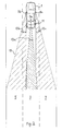
- a vehicle 1 is shown, which is located in the middle lane 3 of a three-lane highway.
- the left and right lanes are labeled 5 and 7, respectively.
- a measuring head 9 of a distance measuring device 11, preferably a laser pulse device, is arranged.
- the distance measuring device 11 is connected to an evaluation device (not shown).
- the measuring head 9 scans an angular range of ⁇ 15 °, which is represented by the curved double arrow 13.
- the angular range is divided into a large number of small angular partial ranges ⁇ 1 to ⁇ n, each of which involves a scanning step 15 (as shown in the left lane 5) or, depending on the embodiment, as described below, an overlap gap 17 (as shown in the right lane 7) represent.
- the smallest relevant objects are motorcycles that have a reflectivity sufficient for the measurement over a length of approx. 2 m.
- For the coverage gap 17, its value as delta s a value that is even higher can be used. Applied to practice, these considerations lead to the values N of required scan steps 15 shown in Table A.
- Table 1 Number N of the required scanning steps 15 with different coverage gaps 17 (delta s) for the angular range -15 ° ⁇ ⁇ + 15 ° for the distances 100 m and 200 m.
- the width of the scanning steps 15 is between 1.0 and 2.4 ° for small distances and decreases to approximately 0.1 ° for large distances.
- the number of scan steps 15 per scan can be further reduced if the coverage gap 17 is increased from relatively small values Delta s at short distances to larger values Delta s for the longer distances. This takes into account the fact that at larger distances only the higher differential speeds are relevant for the overhaul recommendation.
- a further reduction in the number N of scan steps 15 per scan is possible if successive scans are formed “intermeshing”.
- Another possibility for reducing the number of steps N is based on the use of the "previous knowledge" that the system has based on the previous measurements of the traffic situation. Rules can be formulated that specify where the occurrence of a signature is plausible in an additional scan.
- FIG. 2 shows a vehicle 1 which is equipped with a distance measuring device 11 with three measuring heads 9a, 9b and 9c.
- the measuring head 9a is located in the center of the vehicle 1, and the measuring heads 9b and 9c are arranged in the left and right wing mirrors, respectively.
- the scan areas which are formed by the individual measuring heads 9a-9c are represented by double arrows 13a, 13b and 13c.
- the scanning area 13b is set in such a way that its right-hand boundary seen in the direction of travel runs essentially parallel to the central lane 3. Its left boundary 19 is selected so that the left lane 5 is completely detected in the more distant area.
- the scanning area of the right measuring head 9c is set mirror-symmetrically to this and covers the more distant area of the right lane 7.
- the central area behind the vehicle 1, as described above with reference to FIG. 1, is monitored by a measuring head 9a placed centrally above the rear window, which, however, has a significantly smaller scanning area than that according to FIG. 1.
- This embodiment offers the advantage that the time required for a scan can be significantly reduced due to the smaller monitoring areas in each case.
- the width ⁇ of the scanning steps 15 can also be reduced (higher number of scanning steps N) in order to ensure a more precise measurement, or a combination of both options is selected. If the amount of equipment is to be kept low, it makes sense to control all measuring heads 9a to 9c in a time-division multiplexing process from a central transmitting and receiving device via optical fibers.
- the embodiment according to FIG. 2 thus enables a large one Field of view on the left and right lane 5,7, which is particularly useful when driving in a convoy.
- a practical exemplary embodiment is intended to show which considerations are to be taken into account when designing the logic for calculating an evaluation or hazard index.
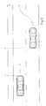
- FIG. 3 shows a traffic sketch with two vehicles 1, 2, of which vehicle 1 starts to change lanes. An axis is shown next to the lane, on which the distance traveled x is plotted from the lane change process.
- the distance to the rear vehicle 2 is denoted by -S o .
- index 1 relates to the front vehicle 1 and index 2 to the rear vehicle 2.
- the time that has elapsed since the start of the lane change process is designated by t.
- the speed of vehicles 1, 2 is denoted by v, where v20 then means, for example, the speed of vehicle 2 at the start of the lane change process.
- the acceleration of vehicles 1, 2 is denoted by a.
- the determination of the maximum necessary scan angle for different initial situations is based on the following consideration:
- the determination of the speed v of vehicles in the adjacent lane is only necessary if the distances still allow an adaptation of the speed by braking and acceleration.
- the minimum safety distance is defined by the distance that the vehicle 2 still travels without braking when the vehicle 1 initiates a braking operation.
- Table 2 gives an overview of the safety distances s min that result from the selection of predefined speeds.
- the time required for a scan can be reduced for smaller monitoring areas.
- the width ⁇ of the scanning steps 15 can also be reduced (higher number of scanning steps N) in order to ensure a more precise measurement, or a combination of both options is selected.
- a map can be calculated depending on the parameters v, a, s, which includes the scan angle ⁇ and the for all common traffic situations
- the distance measuring device 11 is thus designed in such a way that the distances to the following traffic can be measured in a range of 14 m ⁇ m ⁇ 260 m.
- the power of the measuring head 9 is to be dimensioned such that a range of about 1.5 to 2 times the visual range of the human eye is achieved in fog.
- the visibility of the following traffic on rain-soaked lanes should be ensured through one's own spray train and through that of a following vehicle. For this reason too, the measuring head 9 should be arranged as high as possible on the vehicle.
- the decision as to whether a lane change is possible without risk depends on the reliable determination of the extent to which a following vehicle has to brake in order not to fall below the minimum permitted safety distance at any time. A faulty measurement may require the following vehicle 2 to be braked to an undesirable extent and thus cause a dangerous traffic situation.
- the valuation index determined according to the considerations above (right column of table 4) for different traffic situations is indicated by means of a display 21, as shown for example in FIG. 4 integrated in an outside mirror 23.
- the display 21 has four light-emitting diodes 25a-25d, the brightness of which is controlled as a function of the outside light by means of a photodiode 27. On request, the display is permanent or at the request of the driver.
- the upper light-emitting diode 25a is red
- the two middle light-emitting diodes 25b, 25c are yellow
- the lower light-emitting diode 25d is green
- the two yellow light-emitting diodes 25b, 25c being arranged offset to one another.
- the five different character combinations mentioned at the beginning which are assigned to corresponding evaluation or hazard indices, can thus be displayed in a clearly recognizable manner. It is useful to provide the left and right wing mirrors 23 with a display 21 each. This ensures that there is always a clear reference to the intended driving maneuver and that the blind spot not monitored by the measuring head 9 is also checked with the same head movement using a suitably designed mirror.
- the display 21 is arranged in the root or the corner of the exterior mirror 23 facing the vehicle.
- the measuring head 9 for the lane change aid inevitably also monitors the rear near area.
- a suitable measurement and evaluation strategy can therefore also be used to implement a rear pre-crash sensor with little additional effort.
Abstract
Description
Die Erfindung bezieht sich auf ein Verfahren und eine Vorrichtung zum Messen und Auswerten des Abstands eines Kraftfahrzeugs zu einem nachfolgenden Kraftfahrzeug, bei welchem die Messung und Auswertung in dem vorderen Kraftfahrzeug durchgeführt werden, und auf eine Vorrichtung in einem Kraftfahrzeug zur Durchführung des Verfahrens.The invention relates to a method and a device for measuring and evaluating the distance of a motor vehicle from a following motor vehicle, in which the measurement and evaluation are carried out in the front motor vehicle, and to a device in a motor vehicle for carrying out the method.
Es ist hinreichend bekannt, daß beim Führen eines Kraftfahrzeugs der vordere Bereich gut übersehen und - zumindest bei guter Sicht - Entfernungen und Geschwindigkeiten hinreichend zuverlässig eingeschätzt werden können. Beim hinteren Bereich besteht jedoch das Problem, daß der rückwärtige Verkehr nur über Spiegel bzw. durch Wenden des Kopfes und nur für kurze Zeit erfaßt werden kann. Das Schätzen von Entfernungen und mehr noch von Geschwindigkeiten ist dabei selbst bei guter Sicht sehr fehlerbehaftet.It is well known that when driving a motor vehicle the front area is well overlooked and - at least with good visibility - distances and speeds can be estimated with sufficient reliability. In the rear area, however, there is the problem that the rear traffic can only be detected via mirrors or by turning the head and only for a short time. Estimating distances and even more speeds is very error-prone, even with good visibility.
Bei schlechter Sicht - Nacht, Nebel, Blendung, Regen, Gischtkann der Fahrer Entfernungen und Geschwindigkeiten noch schlechter beurteilen, da ihm kaum noch Bezugspunkte in der Umgebung zur Verfügung stehen (Abstandsschätzung aus dem scheinbaren Abstand von Lichtpunkten). Dieser Effekt wird durch die ohnehin verminderte Wahrnehmungsfähigkeit bei Nacht und die extremen Leuchtdichteunterschiede noch verstärkt.In poor visibility - night, fog, glare, rain, spray, the driver can assess distances and speeds even more poorly, since he hardly has any reference points in the area (estimate the distance from the apparent distance from light points). This effect is exacerbated by the already reduced ability to perceive at night and the extreme differences in luminance.
Ein Verfahren der eingangs erwähnten Art ist beispielsweise aus der DE-A-2143406 bekannt. Dort ist ein Doppler-Radar-Gerät beschrieben, mittels dem ein Bereich unmittelbar neben und hinter dem Fahrzeug daraufhin überwacht wird, ob sich dort ein Fahrzeug befindet. Das Gerät ist somit geeignet, die Nachteile des toten Winkels eines Rückspiegels zu umgehen.A method of the type mentioned at the outset is known, for example, from DE-A-2143406. A Doppler radar device is described there, by means of which an area immediately next to and behind the vehicle is monitored to determine whether there is a vehicle there. The device is therefore suitable for avoiding the disadvantages of the blind spot of a rearview mirror.
Bei einem Fahrspurwechsel ist darüberhinaus von erheblicher Bedeutung, wie sich der nachfolgende Verkehr im ferneren Bereich verhält. Ohne direkten Bezug auf den Spurwechsel eines Kraftfahrzeugs zu nehmen, ist es aus der DE-A-1929587 allgemein bekannt, Kollisionen zu vermeiden, indem die beteiligten Fahrzeuge mit einem Sende- und Empfangssystem ausgerüstet sind. Nach dem sogenannten Transponder-Prinzip antwortet Fahrzeug B auf einen Laser-Impuls von Fahrzeug A. Das System kann daher nicht autonom arbeiten und ist relativ aufwendig.When changing lanes, it is also of considerable importance how the following traffic changes in the distance Area behaves. Without directly referring to the lane change of a motor vehicle, it is generally known from DE-A-1929587 to avoid collisions in that the vehicles involved are equipped with a transmission and reception system. According to the so-called transponder principle, vehicle B responds to a laser pulse from vehicle A. The system can therefore not work autonomously and is relatively complex.
Durch die Erfindung wird die Aufgabe gelöst, ein Verfahren und eine Vorrichtung der eingangs genannten Art so auszubilden, daß dem Kraftfahrer eine Information zur Verfügung steht, die ihm beim Fahrspurwechsel hilft, die Verkehrssituation im entfernteren rückwärtigen Bereich zuverlässig zu beurteilen, um ihn bei seiner Entscheidungsfindung bezüglich eines Fahrspurwechsels seines Kraftfahrzeugs zu unterstützen.The invention solves the problem of designing a method and a device of the type mentioned at the beginning in such a way that the driver is provided with information which helps him when changing lanes, reliably assessing the traffic situation in the more distant rear area, in order to assist him in his decision-making to assist with a change of lane of his motor vehicle.
Diese Aufgabe wird bezüglich des Verfahrens dadurch gelöst, daß aus mehreren in vorbestimmtem Zeitabstand aufeinander folgenden Abstandsmeßwerten diejenige Differenzbeschleunigung beider Kraftfahrzeuge ermittelt wird, die zur Einhaltung des notwendigen Sicherheitsabstandes zwischen beiden Fahrzeugen erforderlich wäre, und unter Berücksichtigung der ermittelten Differenzbeschleunigung beider Kraftfahrzeuge ein Bewertungsindex gebildet wird, der dem Kraftfahrer optisch und/oder akustisch angezeigt wird.With regard to the method, this object is achieved in that the differential acceleration of the two motor vehicles that would be required to maintain the necessary safety distance between the two vehicles is determined from a plurality of distance measurement values which follow one another at a predetermined time, and an evaluation index is formed taking into account the determined differential acceleration of the two motor vehicles which is visually and / or acoustically displayed to the driver.
Der Erfindung liegt dabei die Erkenntnis zugrunde, daß nicht allein die Momentanwerte von Geschwindigkeit und Abstand des nachfolgenden Fahrzeugs relevant sind, sondern daß auch das aktuelle Verhalten des nachfolgenden Verkehrs, also ob abgebremst oder weiter beschleunigt wird, in Betracht zu ziehen ist.The invention is based on the knowledge that not only the instantaneous values of speed and distance of the following vehicle are relevant, but also that the current behavior of the following traffic, that is to say whether braking or accelerating further, has to be taken into account.
Kombiniert man das Verhalten des nachfolgenden Verkehrs mit dem eigenen Beschleunigungsverhalten, so läßt sich der Bewertungsindex bilden. Bei der einfachsten Gestaltung des Bewertungsindex ist vorgesehen, den Wert der errechneten, für das sichere Wechseln notwendigen Differenzbeschleunigung analog dem Fahrer anzuzeigen. Die Bewertung im Hinblick auf die Gefährlichkeit des Spurwechselvorgangs verbleibt allein beim Fahrer. Der Bewertungsindex gibt dann darüber Auskunft, ob ein Spurwechsel überhaupt gefahrlos möglich ist, und wenn ja, welche Beschleunigung des eigenen Fahrzeugs nötig ist.If you combine the behavior of the following traffic with your own acceleration behavior, you can create the evaluation index. In the simplest design of the evaluation index, the value of the calculated differential acceleration necessary for the safe change is provided analogously to notify the driver. The driver remains solely responsible for assessing the dangerousness of the lane change process. The rating index then provides information as to whether it is safe to change lanes at all and, if so, which acceleration of your own vehicle is necessary.
Bei einer verfeinerten Ausführungsform ist vorgesehen, die theoretisch möglichen Werte des Bewertungsindex in Teilbereiche zu gliedern, die jeweils einer Spurwechselempfehlung entsprechen.In a refined embodiment, it is provided that the theoretically possible values of the evaluation index are divided into sub-areas, each of which corresponds to a lane change recommendation.
So z.B. bewertet die Spurwechselhilfe die gemessenen Daten:
- der Messung zugängliches Sichtfeld (Abschattungen, Kurven)
- Abstand zu anderen Fahrzeugen und der Winkel unter denen diese erscheinen
- Geschwindigkeit anderer Fahrzeuge
- eigenen Geschwindigkeit
in fünf Stufen nach ihrer Gefährlichkeit in Bezug auf einen Spurwechsel. Die Signalisierung erfolgt beispielsweise über eine Farbanzeige in Ampelform.For example, the lane change aid evaluates the measured data:
- field of view accessible for measurement (shadowing, curves)
- Distance to other vehicles and the angle at which they appear
- Speed of other vehicles
- own speed
in five stages according to their danger of changing lanes. The signaling takes place, for example, via a color display in the form of a traffic light.
Spurwechsel ohne Gefahr möglich, d. h. es werden keine nachfolgenden Fahrzeuge erfaßt oder sie fahren mit konstantem, sicheren Abstand.Lane change possible without danger, d. H. no following vehicles are detected or they drive at a constant, safe distance.
Spurwechsel bei zügiger Beschleunigung möglich, erforderliche Differenzbeschleunigung: Delta a < 1 m/s²Lane change possible with rapid acceleration, required differential acceleration: Delta a <1 m / s²
Spurwechsel möglich, wenn dem nachfolgenden Fahrzeug eine mäßige Abbremsung (vom-Gas-gehen) zugemutet werden kann und gleichzeitig zügig beschleunigt wird:
1 m/s² ≦ Delta a < 2 m/s²Lane change possible if the following vehicle can be expected to brake moderately (accelerate) and accelerate quickly at the same time:
1 m / s² ≦ Delta a <2 m / s²
Ein Spurwechsel erfordert auch bei zügiger Beschleunigung ein starkes Abbremsen des nachfolgenden Verkehrs:
2 m/s² ≦ Delta a < 4 m/s²A lane change requires the following traffic to be braked sharply even when accelerating rapidly:
2 m / s² ≦ delta a <4 m / s²
Ein sicherer Spurwechsel erfordert eine Differenzbeschleunigung:
Delta a ≧ 4 m/s²A safe lane change requires differential acceleration:
Delta a ≧ 4 m / s²
Bei der roten Stufe kann ein akustisches Warnsignal ausgelöst werden, wenn ein ermittelter Lenkeinschlag auf eine irrtümliche Nichtbefolgung der negativen Aussage der Spurwechselhilfe schließen läßt, die eine Kollision zur Folge hätte.At the red level, an acoustic warning signal can be triggered if a determined steering lock suggests an erroneous non-compliance with the negative statement of the lane change aid, which would result in a collision.
Es ist sinnvoll, die Delta a-Grenzwerte als Funktion der eigenen Geschwindigkeit, der Gangstufe und des Fahrzeugstyps zu gestalten, um der unterschiedlichen Beschleunigungsfähigkeit Rechnung zu tragen.It makes sense to design the delta a limits as a function of your own speed, gear and vehicle type in order to take into account the different acceleration capabilities.
Falls das rückwärtige Sichtfeld teilweise verdeckt oder durch Kurven nicht einsehbar ist, wird eine bedingte Empfehlung (z. B. gelb blinkend) ausgegeben. Sie wird beim Ausscheren laufend aktualisiert, so daß eine kurzfristige Reaktion möglich bleibt. Die Anzeige "gelb blinkend" erscheint auch, wenn die gemessenen Daten für die Auswertelogik unplausibel sind.If the rear field of vision is partially covered or cannot be seen through curves, a conditional recommendation (e.g. flashing yellow) is issued. It is continually updated when it leaves the swivel so that a short-term reaction remains possible. The "flashing yellow" display also appears if the measured data are implausible for the evaluation logic.
Es ist empfehlenswert, in den Bewertungsindex Informationen über einen bestimmten Mindestabstand einzuarbeiten, der während des gesamten Spurwechselvorgangs nicht unterschritten werden sollte. Der Mindestabstand ergibt sich dabei aus der Geschwindigkeit des nachfolgenden Fahrzeugs unter Berücksichtigung der menschlichen Reaktionszeiten im Straßenverkehr. Der Bewertungsindex dient dann als Gefahrenindex, der unmittelbar die Gefahr indiziert, die mit dem Spurwechselvorgang verbunden ist. Es wird also in jedem Anzeigebereich oder jeder Anzeigestufe gefordert, daß der Abstand des Hintermannes im Augenblick des Ausscherens auch bei leichter Unaufmerksamkeit eine rechtzeitige Reaktion zuläßt. Dies ist insbesondere bei geringen Differenzgeschwindigkeiten erforderlich, die nur aufgrund der Schätzung der notwendigen Beschleunigung eine niedrige Gefahrbewertung ergeben würden. Als Nährungswert für den Mindestabstand wird in Anlehnung an bekannte Untersuchungen die Strecke gewählt, die das nachfolgende Fahrzeug in der Zeit zurücklegt, die sein Fahrer für Blickzuwendung, Korrektursaccade, Reaktion und muskuläre Umsetzung benötigt. Sie beträgt für 98 % der untersuchten Fahrer weniger als 1,14 s.It is advisable to include information about a certain minimum distance in the evaluation index, which should not be undercut during the entire lane change process. The minimum distance results from the speed of the vehicle behind, taking into account the human reaction times in road traffic. The rating index then serves as a hazard index that directly indicates the hazard associated with the lane change process. It is therefore required in every display area or display level that the distance behind the person at the moment of swinging out also easy inattentiveness allows a timely response. This is particularly necessary at low differential speeds, which would only result in a low risk assessment based on the estimation of the necessary acceleration. Based on known examinations, the route that the following vehicle travels in the time that its driver needs for looking at the eye, corrective correction, reaction and muscular implementation is selected as the approximate value for the minimum distance. For 98% of the drivers examined, it is less than 1.14 s.
Bezüglich der Vorrichtung wird die Aufgabe erfindungsgemäß dadurch gelöst, daß ein Entfernungsmeßgerät im Heckbereich des Kraftfahrzeugs angeordnet ist, mit dessen zugeordnetem Meßkopf ein vorgebbarer Winkelbereich abscanbar ist, daß das Entfernungsmeßgerät mit einer Auswertevorrichtung verbunden ist, deren Logik aus den Signaturen von zumindest zwei aufeinander folgenden Scans die bei einem Spurwechsel notwendige Differenzbeschleunigung und den Abstand der beiden Kraftfahrzeuge voneinander ermittelt und die in Abhängigkeit von den ermittelten Werten den Bewertungs- bzw. Gefahrenindex bildet, und daß eine Anzeigevorrichtung vorgesehen ist, mittels der der Bewertungs- bzw. Gefahrenindex optisch und/oder akustisch angezeigt wird.With regard to the device, the object is achieved in that a distance measuring device is arranged in the rear area of the motor vehicle, with the associated measuring head of which a predeterminable angular range can be scanned, that the distance measuring device is connected to an evaluation device whose logic is based on the signatures of at least two successive scans the differential acceleration required when changing lanes and the distance between the two motor vehicles are determined and which forms the evaluation or hazard index depending on the determined values, and that a display device is provided by means of which the evaluation or hazard index is optically and / or acoustically is shown.
Es kommen prinzipiell alle bekannten Arten vor Entfernungsmeßgeräten infrage, wie beispielsweise ein Radargerät oder ein Infrarotgerät, doch zeichnet sich eine besonders vorteilhafte Ausführungsform der Erfindung dadurch aus, daß das Entfernungsmeßgerät ein Laserpulsgerät ist, das vorzugsweise eine Strahldivergenz im Bereich von 0,05° bis 2° aufweist. Dadurch werden die Störanfälligkeit der Messung von außen und die Beeinflussung der Umgebung durch das Meßverfahren klein gehalten.In principle, all known types can be used in front of distance measuring devices, such as a radar device or an infrared device, but a particularly advantageous embodiment of the invention is characterized in that the distance measuring device is a laser pulse device, which preferably has a beam divergence in the range from 0.05 ° to 2 ° has. As a result, the susceptibility of the measurement from outside and the influence of the environment by the measuring method are kept small.
Weitere Vorteile und Ausgestaltungen der Erfindung ergeben sich aus der Beschreibung eines Ausführungsbeispiels anhand der Figuren. Es zeigen:
- Fig. 1
- ein Kraftfahrzeug mit Entfernungsmeßgerät im Heckbereich,
- Fig. 2
- ein Kraftfahrzeug mit drei Meßköpfen,
- Fig. 3
- eine Verkehrsskizze bei beabsichtigtem Fahrspurwechsel und
- Fig. 4
- einen seitlichen Rückspiegel mit integrierter Anzeigevorrichtung für den Bewertungsindex oder Gefahrenindex.
- Fig. 1
- a motor vehicle with a distance measuring device in the rear area,
- Fig. 2
- a motor vehicle with three measuring heads,
- Fig. 3
- a traffic sketch with intended lane change and
- Fig. 4
- a side rear-view mirror with integrated display device for the rating index or hazard index.
In Figur 1 ist ein Fahrzeug 1 dargestellt, das sich auf der mittleren Fahrspur 3 einer dreispurigen Autobahn befindet. Die linke und rechte Spur sind mit 5 bzw. 7 bezeichnet. Im Heckbereich des Fahrzeugs 1 ist möglichst hoch, z.B. oberhalb der Heckscheibe, ein Meßkopf 9 eines Entfernungsmeßgeräts 11, vorzugsweise eines Laserpulsgeräts, angeordnet. Das Entfernungsmeßgerät 11 ist mit einer Auswertevorrichtung (nicht gezeigt) verbunden.In Figure 1, a
Der Meßkopf 9 scant einen Winkelbereich von ±15° ab, der durch den gekrümmten Doppelpfeil 13 dargestellt wird. Der Winkelbereich ist in eine Vielzahl kleiner Winkelteilbereiche αl bis αn aufgeteilt, die jeweils einen Scanschritt 15 (wie bei der linken Fahrspur 5 gezeigt) oder aber je nach Ausführungsform, wie nachfolgend beschrieben wird, eine Überdeckungslücke 17 (wie bei der rechten Fahrspur 7 gezeigt) darstellen.The measuring head 9 scans an angular range of ± 15 °, which is represented by the curved
Das Laserpuls-Enfernungsmeßgerät 11 arbeitet mit einer apparativ vorgegebenen Strahldivergenz. Sie wird aus denteilweise widersprüchlichen - Forderungen:
- minimale Sendeleistung (Augensicherheit, Lebensdauer der Sendedioden),
- geforderte Reichweite,
- Reflektivität der anzumessenden Objekte,
- Absorption der Atmosphäre (Nebel),
- geometrische Aufweitung des Strahls und damit Verwischung des Zielpunktes
ermittelt und liegt im Bereich von ca. 0,05°
- minimal transmission power (eye safety, service life of the transmission diodes),
- required range,
- Reflectivity of the objects to be measured,
- Absorption of the atmosphere (fog),
- geometric expansion of the beam and thus blurring of the target point
determined and lies in the range of approx. 0.05 ° to 2 °. For the following considerations, 0.1 ° beam divergence is assumed, which corresponds to a beam diameter of approx. 35 cm at a distance of 200 m.
Auf der rechten bzw. linken Straßenberandung ergibt sich eine Meßfläche, deren Größe mit zunehmendem Abstand bzw. abnehmendem Scanwinkel rasch anwächst (in 200 m Abstand 13,3 m, in 100 m Abstand 3,34 m). Es ist daher relativ aufwendig, die Scanwinkel so zu wählen, daß die Meßflächen den interessierenden Entfernungsbereich dicht oder gar überlappend überdecken. Dazu sind bei einem Winkelbereich von ± 15° ca. 300 Scanschritte 15 notwendig. Bei einer angenommenen Dauer pro Scan von 200 ms bleiben pro Scanschritt 15 0,67 ms, was hohe Anforderungen an das Entfernungsmeßgerät 11 stellt. Die Anforderungen lassen sich reduzieren, wenn auf ein dichtes Abscannen verzichtet wird. Es reicht aus, die Dichte der Scanpunkte oder Scanschritte 15 so zu wählen, daß die Entfernung eines Objektes in aufeinanderfolgenden Scandurchgängen ermittelt wird. Falls das Objekt in einem Durchgang nicht erfaßt wird, muß es im darauffolgenden wieder erfaßt werden. Wenn eine noch längere Zeitspanne zwischen zwei Erfassungen desselben Objektes liegt, besteht die Gefahr, daß eine eindeutige Zuordnung der z. B. zum Zeitpunkt t = 0 und t = 3 tscan gemessenen Signaturen zu demselben Objekt nicht mehr möglich ist. Zudem wächst die Gefahr falsch positiver Überholempfehlungen.On the right or left boundary of the road there is a measuring surface, the size of which grows rapidly with increasing distance or decreasing scanning angle (13.3 m in 200 m distance, 3.34 m in 100 m distance). It is therefore relatively complex to choose the scanning angle so that the measuring surfaces cover the distance range of interest in a tight or even overlapping manner. For an angular range of ± 15 °, approximately 300
Für die spätere Auswertung sind nur Objekte mit einer endlichen Differenzgeschwindigkeit zum Meßfahrzeug relevant. Die Überdeckungslücke 17 kann daher so gewählt werden, daß Fahrzeuge, die bei der Messung t = 0 nicht erfaßt werden, bei t = tscan in einen Meßbereich gelangt sind. Die kleinsten relevanten Objekte sind Motorräder, die eine für die Messung ausreichende Reflektivität auf einer Länge von ca. 2 m aufweisen. Für die Überdeckungslücke 17 deren Wert als Delta s bezeichnet ist, kann ein noch darüber liegender Wert angesetzt werden. Angwendet auf die Praxis führen diese Überlegungen zu den in Tabelle A dargestellten Werten N von benötigten Scanschritten 15.Only objects with a finite difference in speed to the measuring vehicle are relevant for later evaluation. The
Tabelle 1: Zahl N der erforderlichen Scanschritte 15 bei unterschiedlichen Überdeckunglücken 17 ( Delta s) für den Winkelbereich -15° < α < +15° für die Entfernungen 100 m und 200 m.

Die Weite der Scanschritte 15 liegt zwischen 1,0 und 2,4° für kleine Entfernungen und nimmt für große Entfernungen auf ca. 0,1° ab.The width of the scanning steps 15 is between 1.0 and 2.4 ° for small distances and decreases to approximately 0.1 ° for large distances.
Die Zahl der Scanschritte 15 pro Scan kann weiter abgesenkt werden, wenn die Überdeckungslücke 17 von relativ kleinen Werten Delta s bei kurzen Entfernungen auf größere Werte Delta s für die längeren Distanzen gesteigert wird. Damit wird der Tatsache Rechnung getragen, daß bei größeren Abständen nur die höheren Differenzgeschwindigkeiten für die Überholungsempfehlung relevant sind.The number of scan steps 15 per scan can be further reduced if the
Eine weitere Absenkung der Zahl N der Scanschritte 15 pro Scan ist möglich, wenn aufeinanderfolgende Scans "ineinanderkämmend" gebildet werden. Dabei werden im Scan t = 0 die Winkel α₁, α₃, α₅... angesteuert, im Scan t = ts folgen die Winkel α₀, α₂, α₄... usw.A further reduction in the number N of scan steps 15 per scan is possible if successive scans are formed “intermeshing”. The angles α₁, α₃, α₅ ... are activated in the scan t = 0, the angles α₀, α₂, α₄ ... follow in the scan t = t s .
Eine weitere Möglichkeit zur Absenkung der Schrittzahl N beruht auf der Ausnutzung der "Vorkenntnis", die das System aufgrund der vorausgegangenen Messungen über die Verkehrssituation hat. Es lassen sich Regeln formulieren, die angeben, wo das Auftreten einer Signatur bei einem zusätzlichen Scan plausibel ist.Another possibility for reducing the number of steps N is based on the use of the "previous knowledge" that the system has based on the previous measurements of the traffic situation. Rules can be formulated that specify where the occurrence of a signature is plausible in an additional scan.
In Figur 2 ist ein Fahrzeug 1 gezeigt, das mit einem Entfernungsmeßgerät 11 mit drei Meßköpfen 9a, 9b und 9c ausgerüstet ist. Der Meßkopf 9a befindet sich in der Mitte des Fahrzeugs 1, und die Meßköpfe 9b und 9c sind in dem linken bzw. rechten Außenspiegel angeordnet. Die Scanbereiche, die von den einzelnen Meßköpfen 9a-9c gebildet werden, sind durch Doppelpfeile 13a, 13b, bzw. 13c dargestellt. Beim linken Meßkopf 9b ist der Scanbereich 13b so eingestellt, daß seine in Fahrtrichtung gesehen rechte Begrenzung im wesentlichen parallel zur mittleren Fahrbahn 3 verläuft. Seine linke Begrenzung 19 ist so gewählt, daß im entfernteren Bereich die linke Fahrspur 5 vollständig erfaßt wird. Der Scanbereich des rechten Meßkopfes 9c ist spiegelsymmetrisch hierzu eingestellt und deckt den entfernteren Bereich der rechten Fahrspur 7 ab. Der mittlere Bereich hinter dem Fahrzeug 1 wird, wie es zuvor anhand der Figur 1 beschrieben ist, von einem mittig über der Heckscheibe plazierten Meßkopf 9a überwacht, der allerdings einen deutlich kleineren Scanbereich aufweist als der nach Figur 1.FIG. 2 shows a
Diese Ausführungsform bietet den Vorteil, daß die für einen Scan benötigte Zeit aufgrund der jeweils kleineren Überwachungsbereiche deutlich reduziert werden kann. Wahlweise kann auch die Weite α der Scanschritte 15 verkleinert werden (höhere Scanschrittzahl N), um eine genauere Messung zu gewährleisten, oder es wird eine Kombination beider Möglichkeiten gewählt. Wenn der Geräteaufwand klein gehalten werden soll, ist es sinnvoll, von einem zentralen Sende- und Empfangsgerät aus über Lichtleitfasern alle Meßköpfe 9a bis 9c im Zeitmultiplexverfahren anzusteuern.This embodiment offers the advantage that the time required for a scan can be significantly reduced due to the smaller monitoring areas in each case. Optionally, the width α of the scanning steps 15 can also be reduced (higher number of scanning steps N) in order to ensure a more precise measurement, or a combination of both options is selected. If the amount of equipment is to be kept low, it makes sense to control all measuring heads 9a to 9c in a time-division multiplexing process from a central transmitting and receiving device via optical fibers.
Die Ausführungsform gemäß Figur 2 ermöglicht also ein großes Sichtfeld auf die linke und rechte Fahrspur 5,7, was insbesondere bei Kolonnenfahrt nützlich ist.The embodiment according to FIG. 2 thus enables a large one Field of view on the left and
Außerdem besteht bei geeigneter Wahl der Scanbereiche 13b, 13c die Möglichkeit, zusätzlich zum entfernteren Bereich auch den toten Winkel der Außenspiegel abzudecken.In addition, with a suitable choice of the
Anhand der Figur 3 soll an einem praktischen Ausführungsbeispiel gezeigt werden, welche Überlegungen bei der Auslegung der Logik zur Berechnung eines Bewertungs- oder Gefahrenindex zu berücksichtigen sind.On the basis of FIG. 3, a practical exemplary embodiment is intended to show which considerations are to be taken into account when designing the logic for calculating an evaluation or hazard index.
Die Figur 3 zeigt hierzu eine Verkehrsskizze mit zwei Fahrzeugen 1, 2, von denen Fahrzeug 1 zu einem Spurwechselvorgang ansetzt. Neben der Fahrbahn ist eine Achse gezeigt, auf der die zurückgelegte Strecke x ab dem Spurwechselvorgang aufgetragen ist. Auf Höhe der hinteren Stoßstange des Fahrzeugs 1 ist x = O gesetzt. Der Abstand zu dem hinteren Fahrzeug 2 ist mit -So bezeichnet. Im folgenden bezieht sich der Index 1 jeweils auf das vordere Fahrzeug 1 und der Index 2 auf das hintere Fahrzeug 2. Die seit Beginn des Spurwechselvorgangs abgelaufene Zeit ist mit t bezeichnet. Der Index o kennzeichnet die zum Zeitpunkt t = O gemessenen Werte. Die Geschwindigkeit der Fahrzeuge 1, 2 ist mit v bezeichnet, wobei v₂₀ dann z.B. die Geschwindigkeit des Fahrzeugs 2 zu Beginn des Spurwechselvorgangs bedeutet. Die Beschleunigung der Fahrzeuge 1, 2 ist mit a bezeichnet.For this purpose, FIG. 3 shows a traffic sketch with two
Die Ermittlung des maximal notwendigen Scanwinkels für unterschiedliche Ausgangssituationen (s,a,v) beruht auf folgender Überlegung:
Die Ermittlung der Geschwindigkeit v von Fahrzeugen auf der benachbarten Spur ist nur dann erforderlich, wenn die Abstände eine Anpassung der Geschwindigkeit durch Abbremsung und Beschleunigung überhaupt noch erlauben.The determination of the maximum necessary scan angle for different initial situations (s, a, v) is based on the following consideration:
The determination of the speed v of vehicles in the adjacent lane is only necessary if the distances still allow an adaptation of the speed by braking and acceleration.
Ein Spurwechsel ist dann noch möglich, wenn der Abstand s₀, die Differenzgeschwindigkeit Delta v = v₁₀ - v₂₀ und die Differenzbeschleunigung Delta a = a₁ - a₂ eine Anpassung der Geschwindigkeit so ermöglichen, daß ein Sicherheitsabstand Smin zu keinem Zeitpunkt unterschritten wird.A lane change is still possible if the distance s₀, the Differential speed Delta v = v₁₀ - v₂₀ and the differential acceleration Delta a = a₁ - a₂ allow an adjustment of the speed so that the safety distance S min is never exceeded.
Der minimale Sicherheitsabstand ist durch die Strecke definiert, die das Fahrzeug 2 noch ungebremst zurücklegt, wenn vom Fahrzeug 1 ein Bremsvorgang eingeleitet wurde. Bekannte Untersuchungen haben ergeben, daß die dabei auftretende Reaktionszeit tUR für 98% der Autofahrer kleiner als 0,78 s ist. Dabei wird unterstellt, daß der Fahrer von Fahrzeug 2 das Fahrzeug 1 aufgrund des vorausgegangenen Spurwechsels im fovealen Blickfeld hat, sodaß keine Blickzuwendungszeit und keine Korrektursaccaden erforderlich sind. (Bei der späteren Betrachtung zur Spurwechselempfehlung werden die Blickzuwendungszeit und Korrektursaccaden berücksichtigt, sodaß dort der eingangs genannte Wert von tBU = 1,14 s in Ansatz gebracht wird.)The minimum safety distance is defined by the distance that the
Für den einzuhaltenden Sicherheitsabstand gilt daher:
![]()
![]()
The following therefore applies to the safety distance to be observed:
![]()
![]()
Die Tabelle 2 gibt eine Übersicht, welche Sicherheitsabstände smin sich bei einer Auswahl vorgegebener Geschwindigkeiten ergeben.Table 2 gives an overview of the safety distances s min that result from the selection of predefined speeds.
Tabelle 2: Minimale Sicherheitsabstände smin


Damit errechnet sich der notwendige minimale Detektionsabstand s₀ aus (1) und (3) zu
Das Meßgerät ermittelt den kürzesten Abstand zum Objekt. Der für die Auswertung relevante Abstand ergibt sich aus dem Meßwert m durch Berücksichtigung der Spurbreite b zu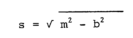
Bei dieser Überschlagsverrechnung wird unterstellt, daß sich der Meßkopf 9 und das nachfolgende Fahrzeug 2 jeweils in der Mitte ihrer Fahrspur befinden. Für die Spurbreite wird in den folgenden Beispielen
b = 3,5 m
angenommen. Realistische Abweichungen in der Straßenbreite ergeben selbst im Bereich s ≈ 15 m einen systematischen Fehler in der Entfernungsbestimmung im Bereich von nur ca.10 cm. Table 2: Minimum safety distances s min
The necessary minimum detection distance s₀ is calculated from (1) and (3)
The measuring device determines the shortest distance to the object. The distance relevant for the evaluation results from the measured value m by taking the track width b into account
With this rough calculation it is assumed that the measuring head 9 and the following
b = 3.5 m
accepted. Realistic deviations in the road width result in a systematic error in the distance determination in the range of only approx. 10 cm even in the area s ≈ 15 m.
Für den Stadtverkehr ergeben sich bei folgender unterstellter Verkehrssituation:
v₁₀ = 40 km/h v₂₀ = 50 km/h
a₁ = 0,8 m/s₂ a₂ = - 2,0 m/s²
für den Mindestabstand ein Wert von S₀ = 10,7 m und für die Geschwindigkeit des Fahrzeugs 2 nach Ablauf der Zeit tmin, zu der sich der Mindestabstand einstellt, ein Wert von v₂ (tmin) = 42,9 km/h.The following assumed traffic situation results for city traffic:
v₁₀ = 40 km / h v₂₀ = 50 km / h
a₁ = 0.8 m / s₂ a₂ = - 2.0 m / s²
a value of S ein = 10.7 m for the minimum distance and a value of v₂ (t min ) = 42.9 km / h for the speed of
Der notwendige Scanwinkel errechnet sich zu α = 14,2°.The necessary scan angle is calculated as α = 14.2 °.
Eine analoge Betrachtung ergibt bei einer Autobahnsituation mit:
v₁₀ = 100 km/h v₂₀ = 120 km/h
a₁ = 0 m/s² a₂ = - 2 m/s²
entsprechende Werte von s₀ = 29,4 m für den Mindestabstand und α = 6,8° für den Scanwinkel. Mit einem Scanwinkel von 15° (½ x Winkel 13) sind also alle Fälle abdeckbar.An analogous consideration results in a motorway situation with:
v₁₀ = 100 km / h v₂₀ = 120 km / h
a₁ = 0 m / s² a₂ = - 2 m / s²
corresponding values of s₀ = 29.4 m for the minimum distance and α = 6.8 ° for the scan angle. With a scan angle of 15 ° (½ x angle 13) all cases can be covered.
Bei einer Anpassung des Scanwinkels kann die für einen Scan benötigte Zeit bei kleineren Überwachungsbereichen reduziert werden. Wahlweise kann auch die Weite α der Scanschritte 15 verkleinert werden (höhere Scanschrittzahl N), um eine genauere Messung zu gewährleisten, oder es wird eine Kombination beider Möglichkeiten gewählt. So z.B. kann anhand der zuvor beschriebenen Rechenvorschriften ein Kennfeld in Abhängigkeit von den Parametern v,a,s berechnet werden, welches für alle gängigen Verkehrssituationen den Scanwinkel α und dieIf the scan angle is adjusted, the time required for a scan can be reduced for smaller monitoring areas. Optionally, the width α of the scanning steps 15 can also be reduced (higher number of scanning steps N) in order to ensure a more precise measurement, or a combination of both options is selected. For example, based on the previously described calculation rules, a map can be calculated depending on the parameters v, a, s, which includes the scan angle α and the for all common traffic situations
Schrittzahl N im Entfernungsmeßgerät 11 einstellt.Sets the number of steps N in the
Der untere und obere Grenzwert für den erforderlichen Detektionsabstand ergibt sich aus folgender Betrachtung:
Bei Extremwerten im Stadtverkehr mit
v₁₀ = 50 km/h v₂₀ = 80 km/h
a₁ = 0 m/s² a₂ = -1 m/s²
ergibt sich ein Detektionsabstand s₀ = 45,6m, beim Losfahren aus einer Parklücke oder einer Einfahrt mit
v₁₀ = 0 km/h v₂₀ = 80 km/h
a₁ = 1,5 m/s² a₂ = -1 m/s²
ergibt sich ein Detektionsabstand s₀ = 109,2 m und bei einer extremen Situation auf der Autobahn mit
v₁₀ = 80 km/h v₂₀ = 250 km/h
a₁ = 0,8 m/s² a₂ = -4,0 m/s²
ergibt sich ein Detektionsabstand s₀ = 256 m.The lower and upper limit for the required detection distance results from the following consideration:
With extreme values in city traffic with
v₁₀ = 50 km / h v₂₀ = 80 km / h
a₁ = 0 m / s² a₂ = -1 m / s²
there is a detection distance s₀ = 45.6m when driving off from a parking space or entering with
v₁₀ = 0 km / h v₂₀ = 80 km / h
a₁ = 1.5 m / s² a₂ = -1 m / s²
this results in a detection distance s₀ = 109.2 m and in an extreme situation on the highway
v₁₀ = 80 km / h v₂₀ = 250 km / h
a₁ = 0.8 m / s² a₂ = -4.0 m / s²
there is a detection distance s₀ = 256 m.
Das Entfernungsmeßgerät 11 ist also so ausgelegt, daß die Messung der Entfernungen zum nachfolgenden Verkehr in einem Bereich von 14 m < m < 260 m möglich ist.The
Dabei wird vorteilhafterweise berücksichtigt, daß die Leistung des Meßkopfes 9 so zu bemessen ist, daß bei Nebel eine Reichweite von etwa der 1,5- bis 2-fachen Sichtweite des menschlichen Auges erreicht wird. Außerdem soll die Erkennbarkeit des nachfolgenden Verkehrs bei regennasser Fahrbahn durch die eigene Gischtschleppe und durch die eines nachfolgenden Fahrzeugs hindurch gewährleistet sein. Auch aus diesem Grund ist der Meßkopf 9 möglichst weit oben am Fahrzeug anzuordnen.It is advantageously taken into account that the power of the measuring head 9 is to be dimensioned such that a range of about 1.5 to 2 times the visual range of the human eye is achieved in fog. In addition, the visibility of the following traffic on rain-soaked lanes should be ensured through one's own spray train and through that of a following vehicle. For this reason too, the measuring head 9 should be arranged as high as possible on the vehicle.
Die Entscheidung, ob ein Spurwechsel gefahrlos möglich ist, hängt von der sicheren Feststellung ab, in welchem Ausmaß ein nachfolgendes Fahrzeug abbremsen muß, um den minimal zulässigen Sicherheitsabstand zu keinem Zeitpunkt zu unterschreiten. Eine Fehlmessung kann ein unerwünscht starkes Abbremsen des nachfolgenden Fahrzeugs 2 erfordern und damit eine gefährliche Verkehrssituation herbeiführen.The decision as to whether a lane change is possible without risk depends on the reliable determination of the extent to which a following vehicle has to brake in order not to fall below the minimum permitted safety distance at any time. A faulty measurement may require the following
Der zulässige Fehler ergibt sich aus dem Meßprozeß:
Schritt 1: t = 0: Fahrzeug 2 befindet sich bei s (0),
Schritt 2: Beim folgenden Scan ist t = ts: Fahrzeug 2 wird erneut erfaßt; Position s (ts)
Schritt 3: Das Gerät ermittelt aus der eigenen Geschwindigkeit v₁₀ und s (0), s (ts), ts die Geschwindigkeit des Fahrzeugs 2:
Schritt 4: Aus v₁₀, v₂₀ und s(ts) wird die bei einem Spurwechsel maximal notwendige Verzögerung a₂ des Fahrzeugs 2 ermittelt, d. h. es wird a₁ = 0 unterstellt.The permissible error results from the measuring process:
Step 1: t = 0:
Step 2: In the following scan, t = t s :
Step 3: The device determines the speed of the
Step 4: From v₁₀, v₂₀ and s (t s ), the maximum necessary deceleration a₂ of the
Die zur Einhaltung des minimalen Sicherheitsabstandes notwendige Verzögerung ergibt sich aus (5) zu
Es ist davon auszugehen, daß die Fehler in der Bestimmung von v₁₀ und ts von untergeordneter Bedeutung sind. Dann ergibt sich der maximal mögliche Fehler im Schätzwert von a₂ zu: (8)
Aus (8) wird deutlich, daß der Fehler in der Bestimmung von a₂ dann sehr groß wird, wenn s (ts) sich vom notwendigen Minimalabstand smin ≈ v₁₀ · tUR nur wenig unterscheidet. Um den kritischen Fall geringer Differenzgeschwindigkeiten und kurzer Abstände zu umgehen, gilt die Auswertevorrichtung nur dann eine Stufe 5 (rot) abweichende Überholempfehlung ab, wenn
s (ts) ≧ v₂₀ · tBU
tBU = 1,46 · tUR = 1,14 s
gilt. Für eine Überholempfehlung sind vorteilhafterweise also die in Tabelle 3 aufgeführten Werte maßgeblich.
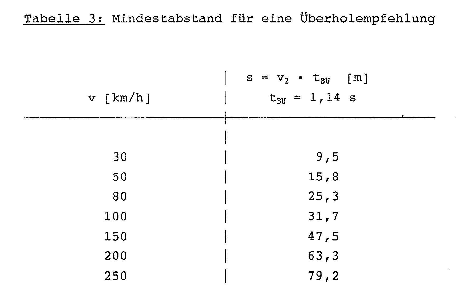
It can be assumed that the errors in the determination of v₁₀ and t s are of minor importance. Then it turns out the maximum possible error in the estimate of a₂ to: (8)
From (8) it is clear that the error in the determination of a₂ becomes very large if s (t s ) differs only slightly from the required minimum distance s min ≈ v₁₀ · t UR . In order to avoid the critical case of low differential speeds and short distances, the evaluation device applies an overtaking recommendation that deviates from level 5 (red) only if
s (t s ) ≧ v₂₀ · t BU
t BU = 1.46t UR = 1.14 s
applies. The values listed in Table 3 are therefore advantageously decisive for an overtaking recommendation.
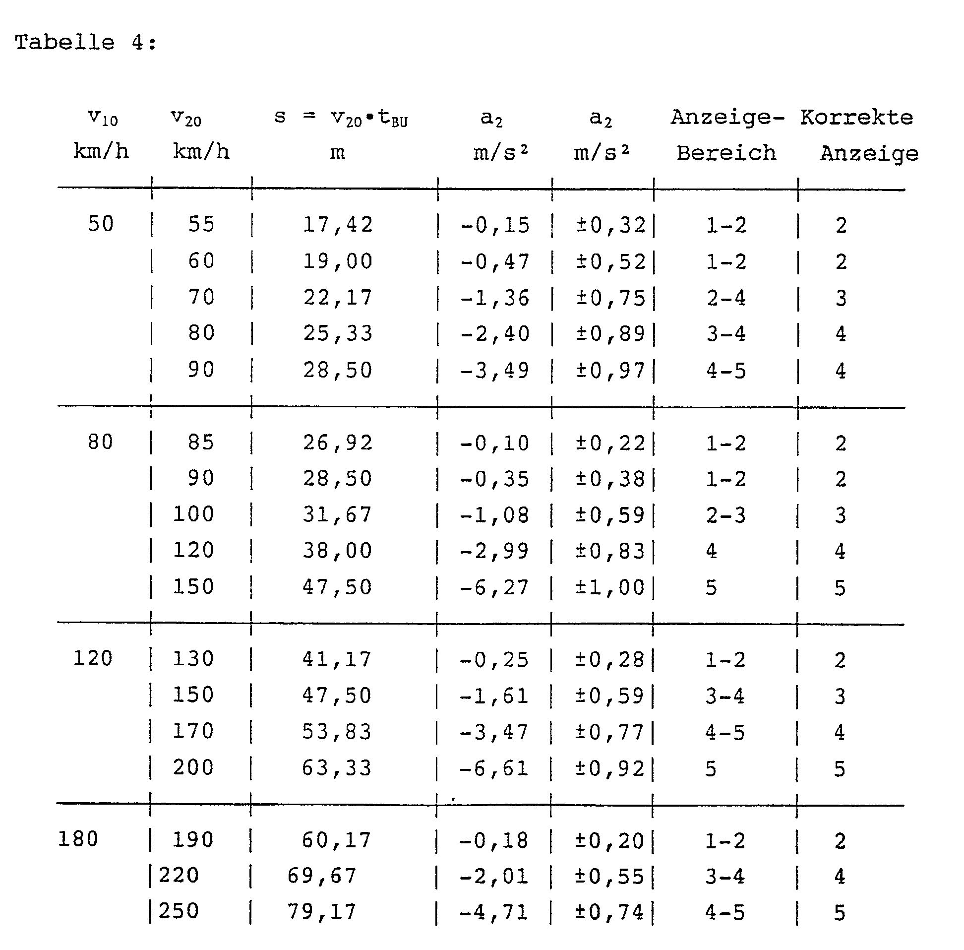
Tabelle 4 zeigt, welcher Schätzfehler sich im ungünstigen Fall bei einem kurzen relevanten Abstand ergeben kann. Dabei wurden folgende Parameter für den Meßprozeß unterstellt:
Delta s = ± 0,15 m
ts = 200 ms
Man erkennt, daß unter diesen relativ ungünstigen Randbedingungen der Fehler in de Indexbildung zur Gefahrenklassifikation in den meisten Fällen nur eine Stufe beträgt.
Delta s = ± 0.15 m
t s = 200 ms
It can be seen that under these relatively unfavorable conditions, the error in the index formation for hazard classification is in most cases only one step.
Der nach obenstehenden Überlegungen ermittelte Bewertungsindex (rechte Spalte der Tabelle 4) für verschiedene Verkehrssituationen wird mittels eines Anzeige-Displays 21, wie es beispielsweise anhand der Figur 4 in einen Außenspiegel 23 integriert dargestellt ist, angezeigt.The valuation index determined according to the considerations above (right column of table 4) for different traffic situations is indicated by means of a
Das Anzeige-Display 21 weist vier Leuchtdioden 25a - 25d auf, deren Helligkeit über eine Fotodiode 27 außenlichtabhängig gesteuert wird. Die Anzeige erfolgt auf Wunsch ständig oder nach Aufforderung durch den Fahrer.The
Die obere Leuchtdiode 25a ist rot, die beiden mittleren Leuchtdioden 25b,25c sind gelb und die untere Leuchtdiode 25d ist grün, wobei die beiden gelben Leuchtdioden 25b,25c versetzt zueinander angeordnet sind. Damit lassen sich die eingangs erwähnten fünf unterschiedlichen Zeichenkombinationen, die entsprechenden Bewertungs- bzw. Gefahrenindices zugeordnet sind, gut erkennbar darstellen. Es ist nützlich, den linken und den rechten Außenspiegel 23 mit je einem Anzeige-Display 21 zu versehen. Damit ist sichergestellt, daß stets ein eindeutiger Bezug zum beabsichtigten Fahrmanöver besteht und mit derselben Kopfbewegung über einen geeignet gestalteten Spiegel auch der vom Meßkopf 9 nicht überwachte tote Winkel abgeprüft wird. Das Anzeige-Display 21 ist in der Wurzel oder der fahrzeugzugewandten Ecke des Außenspiegles 23 angeordnet.The upper light-emitting
Wie bereits erwähnt, können mehrere Meßköpfe 9 über Lichtleitfasern im Zeitmultiplexverfahren angesteuert werden. Das erschließt die Möglichkeit einer Abstandswarnung vorne, die folgende Funktionen erfüllen kann:
- Vermeidung von Auffahrunfällen bei Einfädelmanövern,
- Pre Crash-Sensor vorne,
- Abstand zum Vordermann bei schlechter Sicht,
- Überholhilfe.
- Avoidance of rear-end collisions during threading maneuvers,
- Pre crash sensor in front,
- Distance to the vehicle in front when visibility is poor,
- Overtaking aid.
Der Meßkopf 9 für die Spurwechselhilfe überwacht zwangsläufig auch den hinteren Nahbereich. Durch eine geeignete Meß- und Auswertestrategie kann deswegen außerdem ein Pre-Crash-Sensor hinten mit geringem Zusatzaufwand realisiert werden.The measuring head 9 for the lane change aid inevitably also monitors the rear near area. A suitable measurement and evaluation strategy can therefore also be used to implement a rear pre-crash sensor with little additional effort.
Claims (16)
Applications Claiming Priority (2)
| Application Number | Priority Date | Filing Date | Title |
|---|---|---|---|
| DE4005444A DE4005444A1 (en) | 1990-02-21 | 1990-02-21 | METHOD AND DEVICE FOR SUPPORTING A DRIVER FOR A ROAD TRACK CHANGE |
| DE4005444 | 1990-02-21 |
Publications (3)
| Publication Number | Publication Date |
|---|---|
| EP0443185A2 true EP0443185A2 (en) | 1991-08-28 |
| EP0443185A3 EP0443185A3 (en) | 1991-11-06 |
| EP0443185B1 EP0443185B1 (en) | 1995-02-01 |
Family
ID=6400654
Family Applications (1)
| Application Number | Title | Priority Date | Filing Date |
|---|---|---|---|
| EP90125132A Expired - Lifetime EP0443185B1 (en) | 1990-02-21 | 1990-12-21 | Method and device for assisting a motorist when changing lanes |
Country Status (2)
| Country | Link |
|---|---|
| EP (1) | EP0443185B1 (en) |
| DE (2) | DE4005444A1 (en) |
Cited By (34)
| Publication number | Priority date | Publication date | Assignee | Title |
|---|---|---|---|---|
| DE4307009A1 (en) * | 1992-03-05 | 1993-09-23 | Honda Motor Co Ltd | Multi-beam antenna device for radar system of e.g. automobile - has offset antenna supported by common holder with radar modules each having integral prim. radiator |
| EP0591743A1 (en) * | 1992-10-05 | 1994-04-13 | GILARDINI S.p.A. | Device for detecting relative positions between vehicles, principally for anti-collision purposes |
| GB2312113A (en) * | 1996-04-10 | 1997-10-15 | Fuji Heavy Ind Ltd | Vehicular collision avoidance system |
| DE19757063A1 (en) * | 1997-12-20 | 1999-06-24 | Bayerische Motoren Werke Ag | Safety speed control system for vehicle |
| EP1312506A2 (en) | 2001-11-07 | 2003-05-21 | C.R.F. Società Consortile per Azioni | A method and system for assisting the driver of a motor vehicle in a lane-change manoeuvre |
| WO2004068164A2 (en) * | 2003-01-30 | 2004-08-12 | Schefenacker Vision Systems Germany Gmbh & Co. Kg | Danger recognition system for vehicles, comprising at least one lateral and rear environment detection unit |
| EP1470957A2 (en) * | 2003-04-25 | 2004-10-27 | Audi Ag | Driver assistance system |
| EP1607264A1 (en) * | 2004-06-17 | 2005-12-21 | Robert Bosch GmbH | Lane changing assistance for a vehicle |
| EP1612082A1 (en) * | 2004-06-12 | 2006-01-04 | Robert Bosch Gmbh | Lane-changing assistant for motor vehicle |
| EP1630778A1 (en) * | 2004-08-27 | 2006-03-01 | Audi Ag | Brightness sensor for a display device of a motor vehicle |
| WO2006092431A1 (en) * | 2005-03-03 | 2006-09-08 | Continental Teves Ag & Co. Ohg | Method and device for avoiding a collision as a vehicle is changing lanes |
| WO2006122867A1 (en) * | 2005-05-19 | 2006-11-23 | Robert Bosch Gmbh | Lane change assistant for motor vehicles |
| EP1726481A1 (en) * | 2005-05-23 | 2006-11-29 | Delphi Technologies, Inc. | Vehicle range-based lane change assist system and method |
| WO2007014633A1 (en) * | 2005-08-04 | 2007-02-08 | Daimlerchrysler Ag | Method for assisting the driver of a vehicle when changing lanes and driver-assistance system for carrying out the method |
| EP1752336A1 (en) * | 2005-08-12 | 2007-02-14 | Audi Ag | Method for determining if the duration termining the duration of a warning signal |
| EP1887540A1 (en) * | 2006-08-04 | 2008-02-13 | Volkswagen Aktiengesellschaft | Device and method for avoiding rear-end collisions |
| WO2008017542A1 (en) | 2006-08-11 | 2008-02-14 | Robert Bosch Gmbh | Device for detecting a moving object |
| EP1902338A2 (en) * | 2005-07-06 | 2008-03-26 | Donnelly Corporation | Vehicle exterior mirror assembly with blind spot indicator |
| WO2012080005A1 (en) * | 2010-12-14 | 2012-06-21 | Robert Bosch Gmbh | Method for sensing a wet road |
| US8378802B2 (en) | 2008-08-04 | 2013-02-19 | Smr Patents S.A.R.L. | Exterior rear view mirror with indicator light |
| US9308867B2 (en) | 2010-04-21 | 2016-04-12 | SMR Patents S.à.r.l. | Side rear view mirror assembly indicator of blind spot occupancy |
| WO2016110365A1 (en) * | 2015-01-08 | 2016-07-14 | Volkswagen Aktiengesellschaft | Method and driver assistance system for assisting a driver of a vehicle |
| US9713986B2 (en) | 2006-10-24 | 2017-07-25 | Magna Mirrors Of America, Inc. | Exterior mirror reflective element sub-assembly |
| US9758102B1 (en) | 2005-09-14 | 2017-09-12 | Magna Mirrors Of America, Inc. | Mirror reflective element sub-assembly for exterior rearview mirror of a vehicle |
| US9761144B2 (en) | 2014-09-11 | 2017-09-12 | Magna Mirrors Of America, Inc. | Exterior mirror with blind zone indicator |
| EP3243717A1 (en) | 2016-05-10 | 2017-11-15 | Volkswagen Aktiengesellschaft | Motor vehicle control device and method for operating the control device for autonomous driving of a motor vehicle |
| WO2018192800A1 (en) * | 2017-04-20 | 2018-10-25 | Bayerische Motoren Werke Aktiengesellschaft | Method for assistance of a driving manoeuver, and assistance system for a driving manoeuver |
| US10589686B2 (en) | 2005-07-06 | 2020-03-17 | Donnelly Corporation | Vehicle exterior rearview mirror system having an indicator |
| US10632968B2 (en) | 2011-11-14 | 2020-04-28 | Magna Mirrors Of America, Inc. | Vehicular door handle assembly with illumination module |
| CN112319365A (en) * | 2020-10-23 | 2021-02-05 | 浙江中车电车有限公司 | Lane change early warning auxiliary method and system |
| US11242009B2 (en) | 2005-07-06 | 2022-02-08 | Donnelly Corporation | Vehicular exterior mirror system with blind spot indicator |
| US11351873B2 (en) | 2017-04-20 | 2022-06-07 | Bayerische Motoren Werke Aktiengesellschaft | Driving assistance method for assistance of a power-intensive driving manoeuver of a subject vehicle, and driving assistance system for a power-intensive driving manoeuver of a subject vehicle |
| US11498487B2 (en) | 2005-07-06 | 2022-11-15 | Magna Mirrors Of America, Inc. | Vehicular exterior mirror system with blind spot indicator |
| US11890991B2 (en) | 2006-10-24 | 2024-02-06 | Magna Mirrors Of America, Inc. | Vehicular exterior rearview mirror assembly with blind spot indicator element |
Families Citing this family (23)
| Publication number | Priority date | Publication date | Assignee | Title |
|---|---|---|---|---|
| US5459460A (en) * | 1992-12-11 | 1995-10-17 | Kansei Corporation | Collision warning system |
| DE4313568C1 (en) * | 1993-04-26 | 1994-06-16 | Daimler Benz Ag | Guiding motor vehicle driver when changing traffic lanes - using radar devices to detect velocity and spacing of vehicles in next lane and indicate when lane changing is possible |
| DE19538771B4 (en) * | 1995-10-18 | 2010-04-01 | Visiocorp Patents S.á.r.l. | Exterior rearview mirror for vehicles, preferably for motor vehicles |
| DE19538770B4 (en) * | 1995-10-18 | 2010-08-05 | SMR Patents S.à.r.l. | Exterior rearview mirror for vehicles, preferably for motor vehicles |
| FR2749670B1 (en) † | 1996-06-11 | 1998-07-31 | Renault | DEVICE AND METHOD FOR MEASURING PARKING SPOTS OF A MOTOR VEHICLE |
| DE19835601B4 (en) * | 1998-08-06 | 2007-05-10 | Volkswagen Ag | Assistance system for vehicles |
| DE19839198B4 (en) * | 1998-08-28 | 2004-08-12 | Robert Bosch Gmbh | Method for displaying driver information in a motor vehicle |
| DE19911648A1 (en) * | 1999-03-16 | 2000-09-21 | Volkswagen Ag | Procedure for displaying objects |
| DE19933782B4 (en) * | 1999-07-19 | 2013-08-01 | Volkswagen Ag | Method for avoiding rear-end collisions and device for carrying out the method |
| DE10146808A1 (en) * | 2001-09-22 | 2003-04-10 | Adc Automotive Dist Control | Optical system or motor vehicle has sensor units at different positions in or on vehicle with transmission and reception optics, central module with measurement, control and changeover units |
| DE10148539A1 (en) * | 2001-10-01 | 2003-04-10 | Volkswagen Ag | Driver assistance method for helping a driver in critical conflict or collision situations, involves determining triggering point for initiation of avoidance measures so that the driver is given adequate time to respond himself |
| DE10162009B4 (en) * | 2001-12-18 | 2011-12-15 | Automotive Distance Control Systems Gmbh | Optical system |
| DE10205225A1 (en) * | 2002-02-08 | 2003-11-20 | Bayerische Motoren Werke Ag | Lane change mode activation method, for use with a motor vehicle automatic cruise control or collision avoidance system, in which the probability of a lane change is monitored to accelerate the changeover to lane change mode |
| DE10212756A1 (en) * | 2002-03-22 | 2003-10-16 | Audi Ag | motor vehicle |
| ES2328676T3 (en) | 2002-07-17 | 2009-11-17 | Fico Mirrors, S.A. | ACTIVE SURVEILLANCE DEVICE IN A SAFETY PERIMETER OF A MOTOR VEHICLE. |
| DE10242220A1 (en) * | 2002-09-12 | 2004-03-25 | Valeo Schalter Und Sensoren Gmbh | Motor vehicle lane change warning system, comprises a blind angle area-monitoring unit that generates a warning to a driver if another vehicle or obstacle is in the blind angle area |
| DE10358177B4 (en) * | 2003-12-12 | 2021-09-16 | Volkswagen Ag | Optical display device for a driver assistance system |
| DE102004052667B4 (en) * | 2004-10-29 | 2006-08-17 | Audi Ag | Motor vehicle with a lane change assistance system |
| DE102005013669A1 (en) * | 2005-03-14 | 2006-09-21 | Walter Ostertag | Method for operating motor vehicle involves transfer of information to driver of motor vehicle during forward drive is based on signal supplied by detection device |
| DE102005059415B4 (en) * | 2005-12-13 | 2021-03-11 | Bayerische Motoren Werke Aktiengesellschaft | Lane change assistance system for a vehicle |
| JP6142784B2 (en) | 2013-11-27 | 2017-06-07 | 株式会社デンソー | Driving assistance device |
| DE102013226773A1 (en) * | 2013-12-19 | 2015-06-25 | Volkswagen Aktiengesellschaft | Apparatus, method and computer program for assisting a course change of a vehicle |
| EP3208786B1 (en) * | 2016-02-22 | 2023-06-07 | Volvo Car Corporation | Method and system for evaluating inter-vehicle traffic gaps and time instances to perform a lane change manoeuvre |
Citations (4)
| Publication number | Priority date | Publication date | Assignee | Title |
|---|---|---|---|---|
| US3697985A (en) * | 1970-09-23 | 1972-10-10 | Bendix Corp | Rear end warning system for automobiles |
| GB2004158A (en) * | 1977-09-12 | 1979-03-21 | Nissan Motor | Radar system for detecting approaching vehicles from behind |
| EP0210079A2 (en) * | 1985-07-24 | 1987-01-28 | John W. Davis | Automotive collision avoidance and/or air bag deployment radar |
| EP0381016A1 (en) * | 1989-02-01 | 1990-08-08 | Hohe Kg | External rear view mirror for a motor vehicle |
Family Cites Families (26)
| Publication number | Priority date | Publication date | Assignee | Title |
|---|---|---|---|---|
| GB1300299A (en) * | 1970-10-14 | 1972-12-20 | Mitsubishi Electric Corp | System for preventing collision of vehicles |
| US3701903A (en) * | 1970-10-29 | 1972-10-31 | Honeywell Inc | Piezoelectric vehicle impact sensor |
| DE2156001B2 (en) * | 1971-11-11 | 1975-10-16 | Daimler-Benz Ag, 7000 Stuttgart | Distance warning device for vehicles |
| JPS5450353U (en) * | 1977-09-14 | 1979-04-07 | ||
| JPS5445040A (en) * | 1977-09-16 | 1979-04-10 | Nissan Motor Co Ltd | Rear warning radar device |
| NL7811835A (en) * | 1977-12-08 | 1979-06-12 | Ferranti Ltd | DEVICE FOR GAVING A WARNING IN THE EVENT OF A VEHICLE COLLISION. |
| JPS5819942Y2 (en) * | 1978-05-22 | 1983-04-25 | 日産自動車株式会社 | Automotive outside mirror |
| DE2837483A1 (en) * | 1978-08-28 | 1980-03-20 | Fritz Ing Grad Ott | Focus meter indicating automobile stopping distance - uses light reflected from tachometer-coupled mirror as siting point |
| JPS5596475A (en) * | 1979-01-19 | 1980-07-22 | Nissan Motor Co Ltd | Obstacle detector for vehicle |
| JPS5876784A (en) * | 1981-10-31 | 1983-05-09 | Nissan Motor Co Ltd | Light pulse radar apparatus for vehicles |
| DE3244358C2 (en) * | 1982-12-01 | 1984-10-04 | Daimler-Benz Ag, 7000 Stuttgart | Device for detecting obstacles as a maneuvering aid when parking or turning a motor vehicle |
| DE3303260A1 (en) * | 1983-02-01 | 1984-10-18 | Ferenc Dipl.-Ing. Meggen Luzern Remenyi | Clearance-indicating device |
| DE3313866A1 (en) * | 1983-04-16 | 1984-10-18 | Robert Bosch Gmbh, 7000 Stuttgart | DEVICE FOR DETECTING OTHER VEHICLES IN THE REVISED FIELD OF VIEW OF A VEHICLE |
| CA1187601A (en) * | 1984-03-27 | 1985-05-21 | B.E.L-Tronics Limited | Construction for a portable radar detector having a mirror |
| DE3411545A1 (en) * | 1984-03-29 | 1985-10-10 | Hans-Alex Dr.med. 2812 Hoya Falkenau | Method and device for determining the distance between a motor vehicle and an obstacle |
| DE3500152A1 (en) * | 1985-01-04 | 1986-07-24 | Weber Helga | System for warning that a vehicle is changing carriageway |
| DE3622447C1 (en) * | 1986-07-04 | 1988-01-28 | Daimler Benz Ag | Device for displaying overtaking recommendations for the driver of a vehicle |
| DE3637165A1 (en) * | 1986-10-31 | 1988-05-05 | Rainer Ashauer | Method and device for preventing crashes, especially for motor vehicles in road traffic |
| DE8717494U1 (en) * | 1987-09-15 | 1989-02-09 | Kolbatz, Klaus-Peter, 1000 Berlin, De | |
| DE3810840C1 (en) * | 1988-03-30 | 1989-11-09 | Messerschmitt-Boelkow-Blohm Gmbh, 8012 Ottobrunn, De | |
| DE3816587A1 (en) * | 1988-05-16 | 1989-11-23 | Messerschmitt Boelkow Blohm | DEVICE FOR TRIGGERING A PASSIVE SAFETY DEVICE |
| DE3827879C1 (en) * | 1988-08-17 | 1989-08-24 | Daimler-Benz Aktiengesellschaft, 7000 Stuttgart, De | |
| DE8811563U1 (en) * | 1988-09-13 | 1989-01-26 | Heller, Peter, 3156 Hohenhameln, De | |
| DE3832720A1 (en) * | 1988-09-27 | 1990-03-29 | Bosch Gmbh Robert | DISTANCE MEASURING DEVICE FOR CONTACTLESS DISTANCE AND ANGLE DETECTION |
| DE3930272A1 (en) * | 1988-10-05 | 1990-04-19 | Impulsphysik Gmbh | LIDAR |
| US5026153A (en) * | 1989-03-01 | 1991-06-25 | Mitsubishi Denki K.K. | Vehicle tracking control for continuously detecting the distance and direction to a preceding vehicle irrespective of background dark/light distribution |
-
1990
- 1990-02-21 DE DE4005444A patent/DE4005444A1/en not_active Withdrawn
- 1990-12-21 EP EP90125132A patent/EP0443185B1/en not_active Expired - Lifetime
- 1990-12-21 DE DE59008417T patent/DE59008417D1/en not_active Expired - Lifetime
Patent Citations (4)
| Publication number | Priority date | Publication date | Assignee | Title |
|---|---|---|---|---|
| US3697985A (en) * | 1970-09-23 | 1972-10-10 | Bendix Corp | Rear end warning system for automobiles |
| GB2004158A (en) * | 1977-09-12 | 1979-03-21 | Nissan Motor | Radar system for detecting approaching vehicles from behind |
| EP0210079A2 (en) * | 1985-07-24 | 1987-01-28 | John W. Davis | Automotive collision avoidance and/or air bag deployment radar |
| EP0381016A1 (en) * | 1989-02-01 | 1990-08-08 | Hohe Kg | External rear view mirror for a motor vehicle |
Cited By (74)
| Publication number | Priority date | Publication date | Assignee | Title |
|---|---|---|---|---|
| DE4307009A1 (en) * | 1992-03-05 | 1993-09-23 | Honda Motor Co Ltd | Multi-beam antenna device for radar system of e.g. automobile - has offset antenna supported by common holder with radar modules each having integral prim. radiator |
| DE4307009C2 (en) * | 1992-03-05 | 1999-02-18 | Honda Motor Co Ltd | Reflector radar antenna device |
| EP0591743A1 (en) * | 1992-10-05 | 1994-04-13 | GILARDINI S.p.A. | Device for detecting relative positions between vehicles, principally for anti-collision purposes |
| GB2312113A (en) * | 1996-04-10 | 1997-10-15 | Fuji Heavy Ind Ltd | Vehicular collision avoidance system |
| GB2312113B (en) * | 1996-04-10 | 1998-06-10 | Fuji Heavy Ind Ltd | Drive assist system and method for a vehicle |
| DE19757063A1 (en) * | 1997-12-20 | 1999-06-24 | Bayerische Motoren Werke Ag | Safety speed control system for vehicle |
| US6304811B1 (en) | 1997-12-20 | 2001-10-16 | Bayerische Motoren Werke Aktiengesellschaft | System for controlling speed and distance in a motor vehicle changing traffic lanes |
| EP1312506A2 (en) | 2001-11-07 | 2003-05-21 | C.R.F. Società Consortile per Azioni | A method and system for assisting the driver of a motor vehicle in a lane-change manoeuvre |
| WO2004068164A3 (en) * | 2003-01-30 | 2004-12-02 | Schefenacker Vision Systems | Danger recognition system for vehicles, comprising at least one lateral and rear environment detection unit |
| WO2004068164A2 (en) * | 2003-01-30 | 2004-08-12 | Schefenacker Vision Systems Germany Gmbh & Co. Kg | Danger recognition system for vehicles, comprising at least one lateral and rear environment detection unit |
| EP1470957A2 (en) * | 2003-04-25 | 2004-10-27 | Audi Ag | Driver assistance system |
| EP1470957A3 (en) * | 2003-04-25 | 2007-01-24 | Audi Ag | Driver assistance system |
| EP1612082A1 (en) * | 2004-06-12 | 2006-01-04 | Robert Bosch Gmbh | Lane-changing assistant for motor vehicle |
| EP1607264A1 (en) * | 2004-06-17 | 2005-12-21 | Robert Bosch GmbH | Lane changing assistance for a vehicle |
| US7363140B2 (en) | 2004-06-17 | 2008-04-22 | Robert Bosch Gmbh | Lane changing assistant for motor vehicles |
| EP1630778A1 (en) * | 2004-08-27 | 2006-03-01 | Audi Ag | Brightness sensor for a display device of a motor vehicle |
| WO2006092431A1 (en) * | 2005-03-03 | 2006-09-08 | Continental Teves Ag & Co. Ohg | Method and device for avoiding a collision as a vehicle is changing lanes |
| US7893819B2 (en) | 2005-03-03 | 2011-02-22 | Continetntal Teves AG & Co, oHG | Method and device for avoiding a collision in a lane change maneuver of a vehicle |
| CN101132965B (en) * | 2005-03-03 | 2010-09-29 | 大陆-特韦斯贸易合伙股份公司及两合公司 | Method and device for avoiding a collision as a vehicle is changing lanes |
| WO2006122867A1 (en) * | 2005-05-19 | 2006-11-23 | Robert Bosch Gmbh | Lane change assistant for motor vehicles |
| EP1726481A1 (en) * | 2005-05-23 | 2006-11-29 | Delphi Technologies, Inc. | Vehicle range-based lane change assist system and method |
| US7501938B2 (en) | 2005-05-23 | 2009-03-10 | Delphi Technologies, Inc. | Vehicle range-based lane change assist system and method |
| EP1902338A2 (en) * | 2005-07-06 | 2008-03-26 | Donnelly Corporation | Vehicle exterior mirror assembly with blind spot indicator |
| US11242009B2 (en) | 2005-07-06 | 2022-02-08 | Donnelly Corporation | Vehicular exterior mirror system with blind spot indicator |
| US10589686B2 (en) | 2005-07-06 | 2020-03-17 | Donnelly Corporation | Vehicle exterior rearview mirror system having an indicator |
| US11498487B2 (en) | 2005-07-06 | 2022-11-15 | Magna Mirrors Of America, Inc. | Vehicular exterior mirror system with blind spot indicator |
| EP1902338A4 (en) * | 2005-07-06 | 2009-11-04 | Donnelly Corp | Vehicle exterior mirror assembly with blind spot indicator |
| US7760111B2 (en) | 2005-07-06 | 2010-07-20 | Donnelly Corporation | Vehicle exterior mirror assembly with blind spot indicator |
| US11827155B2 (en) | 2005-07-06 | 2023-11-28 | Magna Mirrors Of America, Inc. | Vehicular exterior rearview mirror assembly with blind spot indicator |
| US7880596B2 (en) | 2005-07-06 | 2011-02-01 | Donnelly Corporation | Vehicle exterior rearview mirror system with blind spot indicator |
| US8164482B2 (en) | 2005-07-06 | 2012-04-24 | Donnelly Corporation | Vehicle exterior rearview mirror system with indicator module |
| WO2007014633A1 (en) * | 2005-08-04 | 2007-02-08 | Daimlerchrysler Ag | Method for assisting the driver of a vehicle when changing lanes and driver-assistance system for carrying out the method |
| EP1752336A1 (en) * | 2005-08-12 | 2007-02-14 | Audi Ag | Method for determining if the duration termining the duration of a warning signal |
| US11072288B2 (en) | 2005-09-14 | 2021-07-27 | Magna Mirrors Of America, Inc. | Vehicular exterior rearview mirror assembly with blind spot indicator element |
| US11285879B2 (en) | 2005-09-14 | 2022-03-29 | Magna Mirrors Of America, Inc. | Vehicular exterior rearview mirror assembly with blind spot indicator element |
| US9758102B1 (en) | 2005-09-14 | 2017-09-12 | Magna Mirrors Of America, Inc. | Mirror reflective element sub-assembly for exterior rearview mirror of a vehicle |
| US10829053B2 (en) | 2005-09-14 | 2020-11-10 | Magna Mirrors Of America, Inc. | Vehicular exterior rearview mirror assembly with blind spot indicator |
| EP1887540A1 (en) * | 2006-08-04 | 2008-02-13 | Volkswagen Aktiengesellschaft | Device and method for avoiding rear-end collisions |
| WO2008017542A1 (en) | 2006-08-11 | 2008-02-14 | Robert Bosch Gmbh | Device for detecting a moving object |
| CN101500841B (en) * | 2006-08-11 | 2013-07-17 | 罗伯特.博世有限公司 | Device for detecting a moving object |
| US9310484B2 (en) | 2006-08-11 | 2016-04-12 | Robert Bosch Gmbh | Device for detecting a moving object |
| US20090210157A1 (en) * | 2006-08-11 | 2009-08-20 | Wei-Chia Lee | Device for Detecting a Moving Object |
| US11623570B2 (en) | 2006-10-24 | 2023-04-11 | Magna Mirrors Of America, Inc. | Vehicular exterior rearview mirror assembly with blind spot indicator module |
| US11077801B2 (en) | 2006-10-24 | 2021-08-03 | Magna Mirrors Of America, Inc. | Vehicular exterior rearview mirror assembly with blind spot indicator module |
| US10369932B2 (en) | 2006-10-24 | 2019-08-06 | Magna Mirrors Of America, Inc. | Mirror reflective element sub-assembly for vehicular exterior rearview mirror assembly |
| US9713986B2 (en) | 2006-10-24 | 2017-07-25 | Magna Mirrors Of America, Inc. | Exterior mirror reflective element sub-assembly |
| US11890991B2 (en) | 2006-10-24 | 2024-02-06 | Magna Mirrors Of America, Inc. | Vehicular exterior rearview mirror assembly with blind spot indicator element |
| US10640047B2 (en) | 2007-03-15 | 2020-05-05 | Magna Mirrors Of America, Inc. | Mirror reflective element sub-assembly for vehicular exterior rearview mirror assembly |
| US8378802B2 (en) | 2008-08-04 | 2013-02-19 | Smr Patents S.A.R.L. | Exterior rear view mirror with indicator light |
| US9308867B2 (en) | 2010-04-21 | 2016-04-12 | SMR Patents S.à.r.l. | Side rear view mirror assembly indicator of blind spot occupancy |
| WO2012080005A1 (en) * | 2010-12-14 | 2012-06-21 | Robert Bosch Gmbh | Method for sensing a wet road |
| US9272676B2 (en) | 2010-12-14 | 2016-03-01 | Robert Bosch Gmbh | Method for detecting a wet road |
| US11840172B2 (en) | 2011-11-14 | 2023-12-12 | Magna Mirrors Of America, Inc. | Vehicular exterior rearview mirror assembly |
| US10632968B2 (en) | 2011-11-14 | 2020-04-28 | Magna Mirrors Of America, Inc. | Vehicular door handle assembly with illumination module |
| US11325564B2 (en) | 2011-11-14 | 2022-05-10 | Magna Mirrors Of America, Inc. | Vehicular illumination system with reconfigurable display element |
| US11007978B2 (en) | 2011-11-14 | 2021-05-18 | Magna Mirrors Of America, Inc. | Vehicular illumination system with reconfigurable display element |
| US11132903B2 (en) | 2014-09-11 | 2021-09-28 | Magna Mirrors Of America, Inc. | Exterior mirror with blind zone indicator |
| US10614719B2 (en) | 2014-09-11 | 2020-04-07 | Magna Mirrors Of America, Inc. | Exterior mirror with blind zone indicator |
| US9761144B2 (en) | 2014-09-11 | 2017-09-12 | Magna Mirrors Of America, Inc. | Exterior mirror with blind zone indicator |
| US10220771B2 (en) | 2015-01-08 | 2019-03-05 | Volkswagen Aktiengesellschaft | Method and driver assistance system for assisting a driver of a vehicle |
| WO2016110365A1 (en) * | 2015-01-08 | 2016-07-14 | Volkswagen Aktiengesellschaft | Method and driver assistance system for assisting a driver of a vehicle |
| EP3243717A1 (en) | 2016-05-10 | 2017-11-15 | Volkswagen Aktiengesellschaft | Motor vehicle control device and method for operating the control device for autonomous driving of a motor vehicle |
| DE102016208000A1 (en) | 2016-05-10 | 2017-11-16 | Volkswagen Aktiengesellschaft | Motor vehicle control device and method for operating the control device for the autonomous guidance of a motor vehicle |
| EP3530537A1 (en) | 2016-05-10 | 2019-08-28 | Volkswagen Aktiengesellschaft | Motor vehicle control device and method for operating the control device for autonomous driving of a motor vehicle |
| US10915110B2 (en) | 2016-05-10 | 2021-02-09 | Volkswagen Ag | Motor vehicle control apparatus and method for operating a control apparatus for autonomously driving a motor vehicle |
| US10303177B2 (en) | 2016-05-10 | 2019-05-28 | Volkswagen Ag | Motor vehicle control apparatus and method for operating a control apparatus for autonomously driving a motor vehicle |
| EP3505414A1 (en) | 2016-05-10 | 2019-07-03 | Volkswagen Aktiengesellschaft | Motor vehicle control device and method for operating the control device for autonomous driving of a motor vehicle |
| CN110325396B (en) * | 2017-04-20 | 2023-03-07 | 宝马股份公司 | Method for assisting a driving maneuver and assistance system for a driving maneuver |
| WO2018192800A1 (en) * | 2017-04-20 | 2018-10-25 | Bayerische Motoren Werke Aktiengesellschaft | Method for assistance of a driving manoeuver, and assistance system for a driving manoeuver |
| US11351873B2 (en) | 2017-04-20 | 2022-06-07 | Bayerische Motoren Werke Aktiengesellschaft | Driving assistance method for assistance of a power-intensive driving manoeuver of a subject vehicle, and driving assistance system for a power-intensive driving manoeuver of a subject vehicle |
| US11260757B2 (en) | 2017-04-20 | 2022-03-01 | Bayerische Motoren Werke Aktiengesellschaft | Method for assistance of a driving maneuver, and assistance system for a driving maneuver |
| CN110325396A (en) * | 2017-04-20 | 2019-10-11 | 宝马股份公司 | For assisting the method for riding manipulation and for the auxiliary system of riding manipulation |
| CN112319365A (en) * | 2020-10-23 | 2021-02-05 | 浙江中车电车有限公司 | Lane change early warning auxiliary method and system |
| CN112319365B (en) * | 2020-10-23 | 2022-01-25 | 浙江中车电车有限公司 | Lane change early warning auxiliary method and system |
Also Published As
| Publication number | Publication date |
|---|---|
| DE4005444A1 (en) | 1991-08-22 |
| DE59008417D1 (en) | 1995-03-16 |
| EP0443185A3 (en) | 1991-11-06 |
| EP0443185B1 (en) | 1995-02-01 |
Similar Documents
| Publication | Publication Date | Title |
|---|---|---|
| EP0443185B1 (en) | Method and device for assisting a motorist when changing lanes | |
| EP3160813B1 (en) | Method for producing a model of the surroundings of a vehicle | |
| EP3041726B1 (en) | Method and device for analyzing driver assistance systems | |
| DE102014002116B4 (en) | Method for operating a driver assistance system for overtaking operations and motor vehicle | |
| DE102015201588B4 (en) | Method and system for performing automatic control of the movement of a vehicle | |
| DE4342257B4 (en) | Driving safety device for a vehicle | |
| DE19639907A1 (en) | Monitoring vehicle in front | |
| EP1554603B1 (en) | Method and device for monitoring dead angles of a motor vehicle | |
| WO2006122867A1 (en) | Lane change assistant for motor vehicles | |
| DE102018130243A1 (en) | Extended scenario for motorway assistants | |
| DE102017113176A1 (en) | Control device of a vehicle | |
| DE102007015032A1 (en) | Method for evaluating how critical driving situation is comprises calculating possible accelerations and decelerations for vehicle and object whose paths are set to cross and deducing time periods in which their paths would overlap | |
| DE102012023107B4 (en) | Method for operating a driver assistance system of a motor vehicle and motor vehicle | |
| EP0952039B1 (en) | Warning device for vehicle driver drowsiness | |
| WO2018054523A1 (en) | Method for warning a driver of a motor vehicle, taking into consideration the current range of vision of the driver, computing device and detection vehicle | |
| DE102018107515A1 (en) | Virtual steering route | |
| WO2005123440A1 (en) | Method for identifying a change in orientation of a vehicle in the near vicinity | |
| EP1422586B1 (en) | Method and device to monitor a car driver by using lane recognition | |
| DE102018009563A1 (en) | A method for displaying an environment of a motor vehicle, computer program product and motor vehicle | |
| DE102014214507A1 (en) | Method for creating an environment model of a vehicle | |
| DE102014214505A1 (en) | Method for creating an environment model of a vehicle | |
| EP1552975B1 (en) | Information system for a vehicle | |
| DE102014214506A1 (en) | Method for creating an environment model of a vehicle | |
| WO2020165078A1 (en) | Driver assistance system and motor vehicle having a driver assistance system of this type | |
| EP3931025B1 (en) | Method for operating a driver information system in an ego-vehicle and driver information system |
Legal Events
| Date | Code | Title | Description |
|---|---|---|---|
| PUAI | Public reference made under article 153(3) epc to a published international application that has entered the european phase |
Free format text: ORIGINAL CODE: 0009012 |
|
| AK | Designated contracting states |
Kind code of ref document: A2 Designated state(s): DE ES FR GB IT SE |
|
| PUAL | Search report despatched |
Free format text: ORIGINAL CODE: 0009013 |
|
| AK | Designated contracting states |
Kind code of ref document: A3 Designated state(s): DE ES FR GB IT SE |
|
| 17P | Request for examination filed |
Effective date: 19911126 |
|
| 17Q | First examination report despatched |
Effective date: 19940103 |
|
| GRAA | (expected) grant |
Free format text: ORIGINAL CODE: 0009210 |
|
| AK | Designated contracting states |
Kind code of ref document: B1 Designated state(s): DE ES FR GB IT SE |
|
| PG25 | Lapsed in a contracting state [announced via postgrant information from national office to epo] |
Ref country code: ES Free format text: THE PATENT HAS BEEN ANNULLED BY A DECISION OF A NATIONAL AUTHORITY Effective date: 19950201 |
|
| REF | Corresponds to: |
Ref document number: 59008417 Country of ref document: DE Date of ref document: 19950316 |
|
| ET | Fr: translation filed | ||
| ITF | It: translation for a ep patent filed |
Owner name: STUDIO JAUMANN |
|
| GBT | Gb: translation of ep patent filed (gb section 77(6)(a)/1977) |
Effective date: 19950323 |
|
| PG25 | Lapsed in a contracting state [announced via postgrant information from national office to epo] |
Ref country code: SE Effective date: 19950501 |
|
| PLBE | No opposition filed within time limit |
Free format text: ORIGINAL CODE: 0009261 |
|
| STAA | Information on the status of an ep patent application or granted ep patent |
Free format text: STATUS: NO OPPOSITION FILED WITHIN TIME LIMIT |
|
| 26N | No opposition filed | ||
| REG | Reference to a national code |
Ref country code: GB Ref legal event code: IF02 |
|
| PGFP | Annual fee paid to national office [announced via postgrant information from national office to epo] |
Ref country code: GB Payment date: 20061221 Year of fee payment: 17 |
|
| PGFP | Annual fee paid to national office [announced via postgrant information from national office to epo] |
Ref country code: IT Payment date: 20061231 Year of fee payment: 17 |
|
| PGFP | Annual fee paid to national office [announced via postgrant information from national office to epo] |
Ref country code: FR Payment date: 20061228 Year of fee payment: 17 |
|
| GBPC | Gb: european patent ceased through non-payment of renewal fee |
Effective date: 20071221 |
|
| REG | Reference to a national code |
Ref country code: FR Ref legal event code: ST Effective date: 20081020 |
|
| PG25 | Lapsed in a contracting state [announced via postgrant information from national office to epo] |
Ref country code: GB Free format text: LAPSE BECAUSE OF NON-PAYMENT OF DUE FEES Effective date: 20071221 |
|
| PG25 | Lapsed in a contracting state [announced via postgrant information from national office to epo] |
Ref country code: FR Free format text: LAPSE BECAUSE OF NON-PAYMENT OF DUE FEES Effective date: 20071231 |
|
| PG25 | Lapsed in a contracting state [announced via postgrant information from national office to epo] |
Ref country code: IT Free format text: LAPSE BECAUSE OF NON-PAYMENT OF DUE FEES Effective date: 20071221 |
|
| PGFP | Annual fee paid to national office [announced via postgrant information from national office to epo] |
Ref country code: DE Payment date: 20100204 Year of fee payment: 20 |
|
| PG25 | Lapsed in a contracting state [announced via postgrant information from national office to epo] |
Ref country code: DE Free format text: LAPSE BECAUSE OF EXPIRATION OF PROTECTION Effective date: 20101221 |