EP0444990A1 - Dispensing device for liquid or pasty products, particularly for cosmetic products - Google Patents
Dispensing device for liquid or pasty products, particularly for cosmetic products Download PDFInfo
- Publication number
- EP0444990A1 EP0444990A1 EP91400363A EP91400363A EP0444990A1 EP 0444990 A1 EP0444990 A1 EP 0444990A1 EP 91400363 A EP91400363 A EP 91400363A EP 91400363 A EP91400363 A EP 91400363A EP 0444990 A1 EP0444990 A1 EP 0444990A1
- Authority
- EP
- European Patent Office
- Prior art keywords
- container
- distribution means
- product
- cylindrical
- Prior art date
- Legal status (The legal status is an assumption and is not a legal conclusion. Google has not performed a legal analysis and makes no representation as to the accuracy of the status listed.)
- Granted
Links
Images

Classifications
-
- B—PERFORMING OPERATIONS; TRANSPORTING
- B05—SPRAYING OR ATOMISING IN GENERAL; APPLYING FLUENT MATERIALS TO SURFACES, IN GENERAL
- B05B—SPRAYING APPARATUS; ATOMISING APPARATUS; NOZZLES
- B05B11/00—Single-unit hand-held apparatus in which flow of contents is produced by the muscular force of the operator at the moment of use
- B05B11/01—Single-unit hand-held apparatus in which flow of contents is produced by the muscular force of the operator at the moment of use characterised by the means producing the flow
- B05B11/02—Membranes or pistons acting on the contents inside the container, e.g. follower pistons
- B05B11/026—Membranes separating the content remaining in the container from the atmospheric air to compensate underpressure inside the container
Definitions
- the present invention relates to a dispensing device, without propellant gas, delivering by manual action doses of product, in particular cosmetic product.
- One solution, to avoid contamination, is to provide a variable volume container for the product to be distributed.
- This container can be a closed pocket made of a movable and deformable wall connected to a manual metering pump without air intake.
- the bag decreases in volume with each dose withdrawn and dispensed by the pump, without the stored sterile product coming into contact with the outside air, which ensures that it maintains its sterility.
- document WO 89/00535 describes a container with multiple walls, comprising a deformable pocket serving as a container for a product to be dispensed.
- This container comprises a neck, which has an opening opening into the pocket and equipped with an element comprising a plurality of projections arranged all around this opening to form a strainer which cannot be blocked by the deformable wall of the pocket; the pocket is tightly fixed by welding to the strainer element.
- the object of the present invention is to provide a dispenser capable of dispensing both liquid products and pasty products, without this resulting in a significant increase in the force to be exerted on the push button of the pump.
- the bag must be able to empty itself as completely as possible of the product that it contains, for reasons of very understandable performance: thus there must be no product trapped in the folds of the bag, quine can be sucked and pushed back by the pump.
- this dispenser must be of simple construction and must in particular avoid welding the deformable pocket onto the dispensing means or the strainer element associated therewith.
- the present invention therefore relates to a device for dispensing a liquid or pasty product, in particular a cosmetic product, comprising a container with at least two concentric walls, the outermost of these walls forming a substantially rigid shell, the innermost of these walls forming a deformable sealed pocket of variable volume serving as a container for the product to be dispensed, the shell being provided with an orifice which maintains the ambient pressure around said pocket, the container carrying a dispensing means capable of '' sealingly sealing and being maneuvered externally to ensure the distribution of the product, this distribution means being associated with an element, which is integral with it and which opens into the pocket, the wall of the pocket having a thickness and a substantially uniform structure and said element comprising, around the opening through which it opens into the pocket, a plurality of projections regularly spaced from each other and oriented towards the bottom of the container to form a strainer which cannot be blocked by the deformable wall of the pocket.
- the dispensing means is a manual pump, which delivers a dose of product to be dispensed by actuation of a push button.
- each projection is a spike having a cylindrical lateral surface which is continued by a rounded end surface. This arrangement avoids any tearing of the squeezed pocket at the end of emptying on the pins, while the element described in document WO 89/00535 has sharp angles which can lead to possible drilling of the deformable pocket.
- each projection is a tongue delimited by rounded faces, in order to avoid any tearing of the pocket.
- the container has a longitudinal axis along which the dispensing means is arranged, the external faces of the tongues being arranged in a cylindrical geometric envelope having as axis the longitudinal axis of said dispensing means, the internal faces of said tongues delimiting a space where the opening of the element.
- the tongues advantageously occupy a surface between 0.3 and 0.7 times the total lateral surface of the cylindrical envelope defined by said external faces. This surface value makes it possible to achieve a good stop for the wall of the pocket without causing excessive pressure drop in the case of the distribution of viscous products.
- the end of each tongue has, on its external face, a chamfer eliminating an edge, which could have damaged the wall of the pocket.
- the opening, through which the element opens into the pocket, can be disposed at a distance d1 from the bottom of the container and at a distance d2 from the zone for fixing the dispensing means to the container, the ratio d1 / d2 being understood in the range of 0.8 to 1.2; in this case, the folding of the pocket under the effect of the dispensing means takes place in an orderly and relatively symmetrical manner without any creation of a product retention zone.
- the dispensing means comprises, inside the container, a body on which the element is fixed, the projections of the element connecting to a frustoconical part of said element, said part widening from the projections up to the area for fixing the dispensing means to the container.
- This frustoconical part creates a guide surface of the pocket which orders, even more, the folding of the pocket.
- the manual pump which has a control tube and is fixed to the container via a crimp cup through which said control tube passes.
- the dispensing means comprises, inside the container, a body on which is formed a cylindrical surface, the element being traversed by a bore and coming to be fitted with hard friction on the cylindrical bearing surface of the distribution means. It is also possible that the element is in one piece with the distribution means.
- a liquid or pasty product dispenser comprising a container 1 with two walls and having a longitudinal axis of symmetry XX.
- the outer wall 2 of this container forms a substantially rigid outer shell.
- the internal wall 3 is mobile and deformable; it has a substantially uniform thickness and structure.
- This internal wall 3 forms a sealed pocket 4, of variable volume, which is housed inside the shell 2 and which serves as a container for the product to be dispensed.
- the shell 2 is provided with an orifice 5 for bringing the pocket to atmospheric pressure 4.
- the container has a neck 10 equipped with a distribution means 11 sealing the pocket 4 in effect.
- the upper edge 12 of the pocket forms a circular ring which rests on the upper edge 13, in the form of a circular ring, of the shell 2.
- the neck 10 has a rim 14 projecting radially, which comprises a frustoconical portion 15, of revolution around of the axis XX, the diameter of which decreases downward in a direction opposite to that of the orifice of the container.
- the distribution means 11 is integral with a circular metal cup 21, the peripheral edge 22 of which is crimped on the rim 14 of the neck 10 of the shell 2, with the interposition of an elastic washer 20.
- the edge 22 exerts pressure on the assembly constituted by the elastic washer 20, the upper edge 12 of the pocket, and the upper edge 13 of the shell; the elastic washer 20 thus serves as a seal between the edge 12 of the pocket and the metal cup 21.
- This cup sealingly fixes the dispensing means 11 which is here in the form of a metering pump 26 comprising a control tube 23, the end of which is surmounted by a plunger 24 with a dispensing nozzle 25.
- the axis of the tube 23 is substantially coincident with the axis of symmetry XX.
- the cup 21 forms, in its central part, a cylindrical recess 30 equipped with a central hole 31 for passage of the tube 23.
- the recess 30 comprises an elastic washer 32 serving as a seal between the cup 21 and the body 33 of the pump 26.
- the body 33 of the pump is delimited by a continuous succession, from top to bottom, of three lateral faces forming cylindrical bearings 34, 35, 36 of axis XX.
- the first 34 of these spans comprises, at its lower part, a frustoconical portion 40, decreasing towards the interior of the container; the cup 21 is crimped onto the surface 34 by compressing the elastic washer 32.
- the second surface 35 has a diameter greater than the diameter of the third surface 36, which is connected to a circular end face 40 opposite the bottom of the container 1 , the suction orifice 41 of the pump opening into said face 40.
- This orifice 41 opens into an element 42 disposed inside the pocket 4.
- the element 42 has a circular opening 43 facing the bottom 44 of the container 1 and in fluid communication with the orifice 41 of the pump 26.
- This element 42 comprises, bordering said opening 43, four tabs 45 regularly spaced one on the other and oriented longitudinally towards the bottom 44 of the container, to form a strainer which cannot be blocked by the wall 3 of the pocket 4.
- Each tab 45 has a length, in the direction XX, equal to the diameter of said opening 43.
- the external faces 50 of these tongues are arranged in a cylindrical geometric envelope of revolution of generatrices parallel to the axis XX.
- Each tongue 45 has one end 51 having an outside chamfer 52.
- the tongues 45 are separated from each other by a space having the overall shape and dimensions of a tongue.
- the external faces 50 of the tongues form, in total, an area equal to half the lateral surface of said cylindrical geometric envelope.
- the element 42 has an external contour of revolution around the axis XX and the external faces 50 of the tongues are continued by a first frustoconical lateral surface 53, which itself continues by a second frustoconical lateral surface 54, the two truncated cones widening towards the neck up to the zone for fixing the distribution means to the container 1.
- the circular base 55 of the upper truncated cone 60 delimited by the second lateral surface 54 comes into contact with an annular projection 61 of the cup 21.
- This projection 61 results from the presence of a groove 62 separating the edge 22 of the cup and its central part forming the recess 30.
- the frustoconical lateral surface 54 is in continuity with the external lateral face of the groove 62 and the inside of the neck 10. This continuity allows continuous support of the wall mobile 3, when, by deformation, for example caused by the pump, it approaches element 42.
- the element 42 comprises, on the other hand, a through bore 64 of axis XX, the lower end of which forms the opening 43.
- the element 42 is fitted with hard friction on the second bearing 35 of the pump body , the bearing surface 35 cooperating to do this with the bore 64.
- FIG. 2 shows a second embodiment of the present invention, in which only the element 180 differs from the corresponding element 42 shown in FIG. 1.
- the identical structures bear reference numbers increased by 100 compared to those used for the realization of Figure 1.
- the element 180 is in the form of a small segment of cylinder of revolution of height equal to twice the length of the tongues which border four in number, the opening 140
- the upper circular face 170 of the element 180 has a rounded edge to avoid any catching with the deformable wall 103 of the pocket in on the contrary favoring any sliding of this wall 103 on the element 180.
- This element comprises a through bore 172 of axis YY, which ends at its lower part by the opening 140.
- the element 180 is fitted with hard friction by its bore 172 on the third cylindrical seat 136 of the pump 133.
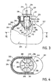
- FIG. 3 and 4 show a third embodiment of the invention.
- the structures identical to those of FIG. 1 bear reference numbers increased by 200 compared to those used for the production of FIG. 1.
- the container 201 is identical to that of FIG. 1.
- the pump 226 comprises a body 233 delimits by a continuous succession, from top to bottom, of two cylindrical bearing surfaces 234, 235.
- the cup is crimped onto the bearing surface 234 as described previously for FIG. 1.
- An element 280 is fitted with hard friction on the lateral bearing surface 235 thanks to a bore 264 arranged along the axis ZZ of said element and of the container.
- This element 280 has a circular opening 243 opposite the bottom 244 of the container and in fluid communication with the orifice 241 of the pump 226.
- the element 280 comprises, bordering said opening 243, three pins 285 regularly spaced from one another and oriented longitudinally towards the bottom 244 of the container, to form a strainer which cannot be blocked by the deformable wall 203 of the pocket 204.
- Each pin 285 has a cylindrical lateral surface of revolution which continues downwards through a rounded end surface 252.
- the pins 285 are in one piece with a frustoconical part 286 flaring towards the neck of the container 201 and arriving in contact with the bottom of the cup 221.
- This frustoconical part 286 has eight regularly spaced grooves 200 and a depth less than the diameter of the section of a pin 285.
- Each groove 200 opens onto the surface of the frustoconical part 286 and is oriented along a generatrix of this surface.
- the function of these grooves is to establish a set of channels where the product to be dispensed can circulate between the wall 203 of the pocket 204 and the element 280.
- the manufacture of the dispensing device according to the invention can be developed in the following manner: a plurality of containers 1, 101, 201 known in the prior art are taken; they are filled with a determined volume of the product to be dispensed. Furthermore, cups 21, 121, 221 are prepared which are each crimped on a manual pump in the manner indicated above.
- the elements 42, 180 or 280, forming a strainer, are force-fitted onto at least one of the cylindrical surfaces of the pump body to give a plurality of intermediate assemblies, which are each directed towards the neck of a corresponding container before to be fixed to it, by crimping the edge of the cup onto the edge of the shell of the bottle.
Abstract
Description
La présente invention concerne un dispositif distributeur, sans gaz propulseur, délivrant par action manuelle des doses de produit, notamment de produit cosmétique.The present invention relates to a dispensing device, without propellant gas, delivering by manual action doses of product, in particular cosmetic product.
On sait que les produits cosmétiques doivent être conditionnés dans les meilleures conditions de stockage et de stérilité. Par ailleurs, il est souhaitable de diminuer et/ou de supprimer les agents de conservation tout en évitant toute contamination d'origine microbienne du produit conditionné dans le distributeur. Une solution, pour éviter toute contamination, est de prévoir un contenant à volume variable pour le produit à distribuer. Ce contenant peut être une poche fermée faite d'une paroi mobile et déformable raccordée à une pompe doseuse manuelle sans reprise d'air. Ainsi la poche diminue de volume à chaque dose prélevée et distribuée par la pompe, sans que le produit stérile stocké n'arrive en contact avec l'air extérieur, ce qui lui assure le maintien de sa stérilité.We know that cosmetic products must be packaged in the best conditions of storage and sterility. Furthermore, it is desirable to reduce and / or eliminate the preservatives while avoiding any microbial contamination of the product packaged in the dispenser. One solution, to avoid contamination, is to provide a variable volume container for the product to be distributed. This container can be a closed pocket made of a movable and deformable wall connected to a manual metering pump without air intake. Thus the bag decreases in volume with each dose withdrawn and dispensed by the pump, without the stored sterile product coming into contact with the outside air, which ensures that it maintains its sterility.
Une telle solution a déjà été proposée, dans la demande de brevet EP 0 182 094, qui décrit un distributeur comprenant un récipient à deux parois séparées concentriques, la paroi intérieure étant mobile et formant une poche étanche déformable contenant le produit à distribuer ; cette poche est raccordée de manière étanche à une pompe sans reprise d'air, qui aspire le contenu de la poche ; la diminution du volume de son contenu entraîne peu à peu un effondrement de la poche qui se plie sur elle-même, car la surface de sa paroi reste constante alors que le volume de son contenu décroît. Le problème se pose, pour ce genre de distributeur, d'assurer la distribution d'un maximum du produit contenu initialement dans la poche, sans que se produise aucun colmatage, par la paroi mobile de la poche, du conduit de sortie, qui débouche à l'intérieur de la poche et se raccorde avec la pompe de distribution. On a prévu de réaliser ce conduit sous la forme d'un tube plongeur axial, dont l'extrémité inférieure définit une ouverture en regard et à très faible distance du fond du récipient. Afin d'éviter un colmatage prématuré du tube plongeur, deux mesures conjointes ont été prévues :
- la première consiste à munir le tube d'au moins un orifice supplémentaire disposé vers le milieu du tube ou vers son ouverture ;
- la seconde consiste à prévoir une poche ayant une paroi d'épaisseur variable pour diriger le pliage de la poche ; on ménage sur la paroi des gorges de moindre épaisseur, qui génèrent un pli lorsque la poche se vide ; l'orientation de ces gorges résulte du procédé même de fabrication par soufflage-extrusion de la poche. Une telle réalisation est complexe et nécessite la coopération d'un long tube plongeur et d'une poche munie de gorges qui est relativement difficile à fabriquer. La longueur du tube plongeur entraîne, en outre, une perte de charge importante si le produit à délivrer est visqueux ou pâteux. Au surplus, il n'est pas exclu que l'ouverture du tube s'obture par contact avec le fond de la poche. Enfin, la fiabilité du pliage correct de la poche autour du tube plongeur est quelque peu douteuse.
- the first consists in providing the tube with at least one additional orifice placed towards the middle of the tube or towards its opening;
- the second consists in providing a pocket having a wall of variable thickness to direct the folding of the pocket; thinner throats are formed on the wall, which generate a fold when the pocket is empty; the orientation of these grooves results from the very process of manufacturing by blowing-extruding the pocket. Such an embodiment is complex and requires the cooperation of a long dip tube and a pocket provided with grooves which is relatively difficult to manufacture. The length of the dip tube also causes a significant pressure drop if the product to be delivered is viscous or pasty. In addition, it is not excluded that the opening of the tube is closed by contact with the bottom of the pocket. Finally, the reliability of the correct folding of the pocket around the dip tube is somewhat doubtful.
Par ailleurs, le document WO 89/00535 décrit un récipient à parois multiples, comportant une poche déformable servant de conteneur à un produit à distribuer. Ce récipient comporte un goulot, qui a une ouverture débouchant dans la poche et équipée d'un élément comportant une pluralité de saillies disposées tout autour de cette ouverture pour former une crépine non colmatable par la paroi déformable de la poche ; la poche est fixée de manière étanche par soudure sur l'élément formant crépine.Furthermore, document WO 89/00535 describes a container with multiple walls, comprising a deformable pocket serving as a container for a product to be dispensed. This container comprises a neck, which has an opening opening into the pocket and equipped with an element comprising a plurality of projections arranged all around this opening to form a strainer which cannot be blocked by the deformable wall of the pocket; the pocket is tightly fixed by welding to the strainer element.
Le but de la présente invention est de proposer un distributeur apte à distribuer aussi bien des produits liquides que des produits pâteux, sans qu'il en résulte une augmentation sensible de la force à exercer sur le bouton-poussoir de la pompe. De plus, la poche doit pouvoir se vider le plus complètement possible du produit qu'elle contient, pour des raisons de rendement bien compréhensibles : ainsi il ne doit pas rester de produit prisonnier dans les plis de la poche, quine puisse être aspiré et refoulé par la pompe. Enfin, ce distributeur doit être de construction simple et doit notamment éviter de souder la poche déformable sur le moyen de distribution ou l'élément-crépine qui lui est associé.The object of the present invention is to provide a dispenser capable of dispensing both liquid products and pasty products, without this resulting in a significant increase in the force to be exerted on the push button of the pump. In addition, the bag must be able to empty itself as completely as possible of the product that it contains, for reasons of very understandable performance: thus there must be no product trapped in the folds of the bag, quine can be sucked and pushed back by the pump. Finally, this dispenser must be of simple construction and must in particular avoid welding the deformable pocket onto the dispensing means or the strainer element associated therewith.
La présente invention a, en conséquence, pour objet un dispositif distributeur de produit liquide ou pâteux, notamment de produit cosmétique, comportant un récipient à au moins deux parois concentriques, la plus externe de ces parois formant une coque sensiblement rigide, la plus interne de ces parois formant une poche étanche déformable de volume variable servant de conteneur pour le produit à distribuer, la coque étant munie d'un orifice qui assure le maintien de la pression ambiante autour de ladite poche, le récipient portant un moyen de distribution susceptible de l'obturer de façon étanche et d'être manoeuvré extérieurement pour assurer la distribution du produit, ce moyen de distribution étant associé à un élément, qui en est solidaire et qui débouche à l'intérieur de la poche, la paroi de la poche ayant une épaisseur et une structure sensiblement uniformes et ledit élément comportant, autour de l'ouverture par laquelle il débouche dans la poche, une pluralité de saillies régulièrement espacées l'une de l'autre et orientées vers le fond du récipient pour former une crépine non colmatable par la paroi déformable de la poche.The present invention therefore relates to a device for dispensing a liquid or pasty product, in particular a cosmetic product, comprising a container with at least two concentric walls, the outermost of these walls forming a substantially rigid shell, the innermost of these walls forming a deformable sealed pocket of variable volume serving as a container for the product to be dispensed, the shell being provided with an orifice which maintains the ambient pressure around said pocket, the container carrying a dispensing means capable of '' sealingly sealing and being maneuvered externally to ensure the distribution of the product, this distribution means being associated with an element, which is integral with it and which opens into the pocket, the wall of the pocket having a thickness and a substantially uniform structure and said element comprising, around the opening through which it opens into the pocket, a plurality of projections regularly spaced from each other and oriented towards the bottom of the container to form a strainer which cannot be blocked by the deformable wall of the pocket.
L'adoption d'une épaisseur et d'une structure sensiblement uniformes de la paroi de la poche entraîne un pliage non dirigé de la poche ; cependant, il s'avère que ce pliage non dirigé n'entraîne aucun colmatage de la crépine définie par les saillies ; le récipient peut être vidé de la quasi-totalité du produit qu'il contient. En contrepartie, l'espace protégé ne pourra être vidé du produit qu'il contient, mais cet espace a un volume extrêmement faible par rapport au volume total du récipient.The adoption of a substantially uniform thickness and structure of the wall of the pocket results in an undirected folding of the pocket; however, it turns out that this non-directed folding does not cause any clogging of the strainer defined by the projections; the container can be emptied of almost all of the product it contains. In return, the protected space cannot be emptied of the product it contains, but this space has an extremely small volume compared to the total volume of the container.
Dans une forme de réalisation préférée, le moyen de distribution est une pompe manuelle, qui délivre une dose de produit à distribuer par actionnement d'un bouton-poussoir.In a preferred embodiment, the dispensing means is a manual pump, which delivers a dose of product to be dispensed by actuation of a push button.
Selon une première variante de réalisation, chaque saillie est un picot ayant une surface latérale cylindrique qui se continue par une surface d'extrémité arrondie. Cette, disposition évite toute déchirure de la poche pressée en fin de vidange sur les picots, alors que l'élément décrit dans le document WO 89/00535 a des angles vifs pouvant entraîner un éventuel perçage de la poche déformable.According to a first alternative embodiment, each projection is a spike having a cylindrical lateral surface which is continued by a rounded end surface. This arrangement avoids any tearing of the squeezed pocket at the end of emptying on the pins, while the element described in document WO 89/00535 has sharp angles which can lead to possible drilling of the deformable pocket.
Selon une deuxième variante de réalisation, chaque saillie est une languette délimitée par des faces arrondies, afin d'éviter toute déchirure de la poche. Le récipient comporte un axe longitudinal selon lequel est disposé le moyen de distribution, les faces externes des languettes étant disposées selon une enveloppe géométrique cylindrique ayant pour axe l'axe longitudinal dudit moyen de distribution, les faces internes desdites languettes délimitant un espace où débouche l'ouverture de l'élément. Dans cette variante, les languettes occupent avantageusement une surface comprise entre 0,3 et 0,7 fois la surface latérale totale de l'enveloppe cylindrique définie par lesdites faces externes. Cette valeur de surface permet de réaliser une bonne butée pour la paroi de la poche sans entraîner de perte de charge excessive dans le cas de la distribution de produits visqueux. De plus, en regard du fond du récipient, l'extrémité de chaque languette comporte, sur sa face externe, un chanfrein supprimant une arête, qui aurait pu endommager la paroi de la poche.According to a second alternative embodiment, each projection is a tongue delimited by rounded faces, in order to avoid any tearing of the pocket. The container has a longitudinal axis along which the dispensing means is arranged, the external faces of the tongues being arranged in a cylindrical geometric envelope having as axis the longitudinal axis of said dispensing means, the internal faces of said tongues delimiting a space where the opening of the element. In this variant, the tongues advantageously occupy a surface between 0.3 and 0.7 times the total lateral surface of the cylindrical envelope defined by said external faces. This surface value makes it possible to achieve a good stop for the wall of the pocket without causing excessive pressure drop in the case of the distribution of viscous products. In addition, facing the bottom of the container, the end of each tongue has, on its external face, a chamfer eliminating an edge, which could have damaged the wall of the pocket.
On peut prévoir que l'ensemble des languettes définisse un espace protégé, dont la section droite est circulaire, chaque languette ayant une longueur comprise entre 0,7 et 1,5 fois le diamètre de la section droite dudit espace protégé ; cette disposition limite la faible quantité du produit non aspirable par la pompe. L'ouverture, par laquelle l'élément débouche dans la poche, peut être disposée à une distance d1 du fond du récipient et à une distance d2 de la zone de fixation du moyen de distribution sur le récipient, le rapport d1/d2 étant compris dans la gamme allant de 0,8 à 1,2 ; dans ce cas, le pliage de la poche sous l'effet du moyen de distribution s'opère de manière ordonnée et relativement symétrique sans aucune création de zone de rétention du produit.Provision may be made for all of the tongues to define a protected space, the cross section of which is circular, each tab having a length of between 0.7 and 1.5 times the diameter of the cross section of said protected space; this provision limits the small amount of product which cannot be sucked up by the pump. The opening, through which the element opens into the pocket, can be disposed at a distance d1 from the bottom of the container and at a distance d2 from the zone for fixing the dispensing means to the container, the ratio d1 / d2 being understood in the range of 0.8 to 1.2; in this case, the folding of the pocket under the effect of the dispensing means takes place in an orderly and relatively symmetrical manner without any creation of a product retention zone.
D'une manière préférée, le moyen de distribution comporte, à l'intérieur du récipient, un corps sur lequel est fixé l'élément, les saillies de l'élément se raccordant à une partie tronconique dudit élément, ladite partie s'évasant depuis les saillies jusqu'à la zone de fixation du moyen de distribution sur le récipient. Cette partie tronconique crée une surface de guidage de la poche qui ordonne, encore plus, le pliage de la poche.Preferably, the dispensing means comprises, inside the container, a body on which the element is fixed, the projections of the element connecting to a frustoconical part of said element, said part widening from the projections up to the area for fixing the dispensing means to the container. This frustoconical part creates a guide surface of the pocket which orders, even more, the folding of the pocket.
Avantageusement, la pompe manuelle, qui comporte un tube de commande et est fixée sur le récipient par l'intermédiaire d'une coupelle de sertissage traversée par ledit tube de commande.Advantageously, the manual pump, which has a control tube and is fixed to the container via a crimp cup through which said control tube passes.
Pour simplifier la mise en oeuvre de l'invention, le moyen de distribution comporte, à l'intérieur du récipient, un corps sur lequel est ménagée une portée cylindrique, l'élément étant traversé par un alésage et venant s'emmancher à frottement dur sur la portée cylindrique du moyen de distribution. Il est également possible que l'élément soit d'un seul tenant avec le moyen de distribution.To simplify the implementation of the invention, the dispensing means comprises, inside the container, a body on which is formed a cylindrical surface, the element being traversed by a bore and coming to be fitted with hard friction on the cylindrical bearing surface of the distribution means. It is also possible that the element is in one piece with the distribution means.
Pour mieux faire comprendre l'objet de l'invention, on va en décrire ci-après, à titre d'exemples purement illustratifs et non limitatifs, plusieurs modes de mise en oeuvre représentés sur le dessin annexé.To better understand the object of the invention, we will describe below, by way of purely illustrative and non-limiting examples, several embodiments shown in the accompanying drawing.
Sur ce dessin :
- la figure 1 représente, en coupe longitudinale avec arrachement, une première forme de réalisation du dispositif distributeur selon l'invention ;
- la figure 2 représente, en coupe longitudinale avec arrachement, une seconde forme de réalisation du dispositif distributeur selon l'invention ;
- la figure 3 représente, en coupe longitudinale, une troisième forme de réalisation du dispositif distributeur selon l'invention ;
- la figure 4 représente une coupe selon IV-IV de la figure 3.
- Figure 1 shows, in longitudinal section with cutaway, a first embodiment of the dispensing device according to the invention;
- 2 shows, in longitudinal section with cutaway, a second embodiment of the dispensing device according to the invention;
- Figure 3 shows, in longitudinal section, a third embodiment of the dispensing device according to the invention;
- FIG. 4 represents a section on IV-IV of FIG. 3.
Sur la figure 1, on voit un distributeur de produit liquide ou pâteux, comportant un récipient 1 à deux parois et possédant un axe longitudinal de symétrie X-X. La paroi externe 2 de ce récipient, forme une coque extérieure sensiblement rigide. La paroi interne 3 est mobile et déformable ; elle a une épaisseur et une structure sensiblement uniformes. Cette paroi interne 3 forme une poche étanche 4, de volume variable, qui est logée à l'intérieur de la coque 2 et qui sert de conteneur au produit à distribuer. La coque 2 est munie d'un orifice 5 de mise à la pression atmosphérique de la poche 4. Le récipient a un col 10 équipé d'un moyen de distribution 11 obturant de manière étanche la poche 4. En effet, le bord supérieur 12 de la poche forme un anneau circulaire qui s'appuie sur le bord supérieur 13, en forme d'anneau circulaire, de la coque 2. Le col 10 possède un rebord 14 en saillie radiale, qui comporte une portion tronconique 15, de révolution autour de l'axe X-X, dont le diamètre diminue vers le bas dans une direction opposée à celle de l'orifice du récipient. Le moyen de distribution 11 est solidaire d'une coupelle métallique circulaire 21, dont le bord périphérique 22 est serti sur le rebord 14 du col 10 de la coque 2, avec interposition d'une rondelle élastique 20. Par coopération avec la portion tronconique 15, le bord 22 exerce une pression sur l'ensemble constitué par la rondelle élastique 20, le bord supérieur 12 de la poche, et le bord supérieur 13 de la coque ; la rondelle élastique 20 sert ainsi de joint d'étanchéité entre le bord 12 de la poche et la coupelle métallique 21. Cette coupelle fixe de manière étanche le moyen de distribution 11 qui se présente ici sous la forme d'une pompe doseuse 26 comportant un tube de commande 23 dont l'extrémité est surmontée d'un poussoir 24 à buse de distribution 25. L'axe du tube 23 est sensiblement confondu avec l'axe de symétrie X-X.In Figure 1, we see a liquid or pasty product dispenser, comprising a container 1 with two walls and having a longitudinal axis of symmetry XX. The outer wall 2 of this container forms a substantially rigid outer shell. The
La coupelle 21 forme, dans sa partie centrale, un évidement cylindrique 30 équipé d'un trou central 31 de passage du tube 23. L'évidement 30 comporte une rondelle élastique 32 servant de joint d'étanchéité entre la coupelle 21 et le corps 33 de la pompe 26. Le corps 33 de la pompe est délimite par une succession continue, du haut vers le bas, de trois faces latérales formant des portées cylindriques 34, 35, 36 d'axe X-X. La première 34 de ces portées comporte, à sa partie inférieure, une portion 40 tronconique, en diminution vers l'intérieur du recipient ; la coupelle 21 est sertie sur la portée 34 en comprimant la rondelle élastique 32. La deuxième portée 35 a un diamètre supérieur au diamètre de la troisième portée 36, qui se raccorde à une face d'extrémité circulaire 40 en regard du fond du récipient 1, l'orifice d'aspiration 41 de la pompe débouchant dans ladite face 40. Cet orifice 41 débouche dans un élément 42 disposé à l'intérieur de la poche 4.The
L'élément 42 présente une ouverture circulaire 43 en regard du fond 44 du récipient 1 et en communication de fluide avec l'orifice 41 de la pompe 26. Cet élément 42 comporte, bordant ladite ouverture 43, quatre languettes 45 régulièrement espacées l'une de l'autre et orientées longitudinalement vers le fond 44 du récipient, pour former une crépine non colmatable par la paroi 3 de la poche 4. Chaque languette 45 a une longueur, suivant la direction X-X, égale au diamètre de ladite ouverture 43. Les faces externes 50 de ces languettes sont disposées selon une enveloppe géométrique cylindrique de révolution de génératrices parallèles à l'axe X-X. Chaque languette 45 a une extrémité 51 présentant extérieurement un chanfrein 52. Les languettes 45 sont séparées l'une de l'autre par un espace ayant globalement la forme et les dimensions d'une languette. Ainsi les faces externes 50 des languettes forment, au total, une surface égale à la moitié de la surface latérale de ladite enveloppe géométrique cylindrique. Dans cette forme de réalisation, l'élément 42 a un contour externe de révolution autour de l'axe X-X et les faces externes 50 des languettes se continuent par une première surface latérale tronconique 53, qui se continue elle-même par une seconde surface latérale tronconique 54, les deux troncs de cône s'évasant vers le col jusqu'à la zone de fixation du moyen de distribution sur le récipient 1. La base circulaire 55 du tronc de cône supérieur 60 délimité par la seconde surface latérale 54 vient au contact d'une saillie annulaire 61 de la coupelle 21. Cette saillie 61 résulte de la présence d'une gorge 62 séparant le bord 22 de la coupelle et sa partie centrale formant l'évidement 30. La surface latérale tronconique 54 est dans la continuité de la face latérale externe de la gorge 62 et de l'intérieur du col 10. Cette continuité permet un soutien continu de la paroi mobile 3, lorsque, par déformation, par exemple provoquée par la pompe, elle se rapproche de l'élément 42.The
L'élément 42 comporte, d'autre part, un alésage traversant 64 d'axe X-X, dont l'extrémité inférieure forme l'ouverture 43. L'élément 42 est emmanché à frottement dur sur la deuxième portée 35 du corps de la pompe, la portée 35 coopérant pour ce faire avec l'alésage 64.The
La figure 2 montre une deuxième forme de réalisation de la présente invention, dans laquelle seul l'élément 180 diffère de l'élément correspondant 42 montré sur la figure 1. Les structures identiques portent des chiffres de référence augmentées de 100 par rapport à ceux utilisés pour la réalisation de la figure 1. On voit que l'élément 180 se présente sous la forme d'un petit segment de cylindre de révolution de hauteur égale à deux fois la longueur des languettes qui bordent au nombre de quatre, l'ouverture 140. La face circulaire 170 supérieure de l'élément 180 a un bord arrondi pour éviter tout accrochage avec la paroi déformable 103 de la poche en favorisant au contraire tout glissement de cette paroi 103 sur l'élément 180. Cet élément comporte un alésage traversant 172 d'axe Y-Y, qui se termine à sa partie inférieure par l'ouverture 140. L'élément 180 est emmanché à frottement dur par son alésage 172 sur la troisième portée cylindrique 136 de la pompe 133.FIG. 2 shows a second embodiment of the present invention, in which only the
Les figures 3 et 4 montrent une troisième forme de réalisation de l'invention. Les structures identiques à celles de la figure 1 portent des chiffres de référence augmentés de 200 par rapport à ceux utilisés pour la réalisation de la figure 1. Le récipient 201 est identique à celui de la figure 1. La pompe 226 comporte un corps 233 délimite par une succession continue, du haut vers le bas, de deux portées cylindriques 234, 235. La coupelle est sertie sur la portée 234 comme décrit précédemment pour la figure 1. Un élément 280 est emmanché à frottement dur sur la portée latérale 235 grâce à un alésage 264 disposé selon l'axe Z-Z dudit élément et du récipient. Cet élément 280 présente une ouverture circulaire 243 en regard du fond 244 du récipient et en communication de fluide avec l'orifice 241 de la pompe 226.Figures 3 and 4 show a third embodiment of the invention. The structures identical to those of FIG. 1 bear reference numbers increased by 200 compared to those used for the production of FIG. 1. The
L'élément 280 comporte, bordant ladite ouverture 243, trois picots 285 régulièrement espacés l'un de l'autre et orientés longitudinalement vers le fond 244 du récipient, pour former une crépine non colmatable par la paroi déformable 203 de la poche 204. Chaque picot 285 a une surface latérale cylindrique de révolution qui se continue vers le bas par une surface d'extrémité arrondie 252. Les picots 285 sont d'un seul tenant avec une partie tronconique 286 s'évasant vers le col du récipient 201 et arrivant en contact avec le fond de la coupelle 221. Cette partie tronconique 286 comporte huit rainures 200 régulièrement espacées et d'une profondeur inférieure au diamètre de la section d'un picot 285. Chaque rainure 200 débouche sur la surface de la partie tronconique 286 et est orientée selon une génératrice de cette surface. La fonction de ces rainures est d'établir un ensemble de canaux où le produit à distribuer peut circuler entre la paroi 203 de la poche 204 et l'élément 280.The
La fabrication du dispositif distributeur selon l'invention peut être élaborée de la manière suivante : on prend une pluralité de récipients 1, 101, 201 connus dans l'état de la technique ; on les remplit d'un volume déterminé du produit à distribuer. Par ailleurs, on prépare des coupelles 21, 121, 221 qui sont chacune sertie sur une pompe manuelle de la manière indiquée précédemment. Les éléments 42, 180 ou 280, formant crépine, sont emmanchés à force sur l'une au moins des portées cylindriques du corps de pompe pour donner une pluralité d'ensembles intermédiaires, qui sont dirigés chacun vers le col d'un récipient correspondant avant d'y être fixés, par sertissage du bord de la coupelle sur le bord de la coque du flacon.The manufacture of the dispensing device according to the invention can be developed in the following manner: a plurality of
Le fonctionnement d'un tel distributeur est classique. A chaque distribution d'une dose de produit par actionnement vers le bas du poussoir 24, 124, 224, la poche 4, 104, 204 se contracte par pliage de sa paroi 3, 103, 203, dans un mouvement d'ensemble en direction de l'orifice d'aspiration 41, 141, 241 de la pompe 26, 126, 226.The operation of such a dispenser is conventional. Each time a dose of product is dispensed by actuating the
Claims (12)
Priority Applications (1)
| Application Number | Priority Date | Filing Date | Title |
|---|---|---|---|
| AT91400363T ATE97030T1 (en) | 1990-02-28 | 1991-02-13 | DISPENSING DEVICE FOR LIQUID OR PASTY PRODUCTS, ESPECIALLY FOR COSMETIC PRODUCTS. |
Applications Claiming Priority (2)
| Application Number | Priority Date | Filing Date | Title |
|---|---|---|---|
| FR9002546 | 1990-02-28 | ||
| FR9002546A FR2658739B1 (en) | 1990-02-28 | 1990-02-28 | DEVICE FOR DISPENSING LIQUID OR PASTY PRODUCT, ESPECIALLY COSMETIC PRODUCT. |
Publications (2)
| Publication Number | Publication Date |
|---|---|
| EP0444990A1 true EP0444990A1 (en) | 1991-09-04 |
| EP0444990B1 EP0444990B1 (en) | 1993-11-10 |
Family
ID=9394250
Family Applications (1)
| Application Number | Title | Priority Date | Filing Date |
|---|---|---|---|
| EP91400363A Expired - Lifetime EP0444990B1 (en) | 1990-02-28 | 1991-02-13 | Dispensing device for liquid or pasty products, particularly for cosmetic products |
Country Status (5)
| Country | Link |
|---|---|
| EP (1) | EP0444990B1 (en) |
| AT (1) | ATE97030T1 (en) |
| DE (1) | DE69100602T2 (en) |
| ES (1) | ES2046861T3 (en) |
| FR (1) | FR2658739B1 (en) |
Cited By (6)
| Publication number | Priority date | Publication date | Assignee | Title |
|---|---|---|---|---|
| FR2685285A1 (en) * | 1991-12-20 | 1993-06-25 | Givenchy Parfums | Method for packaging any liquid product and bottle obtained by this method |
| EP0596142A1 (en) * | 1992-05-11 | 1994-05-11 | Yoshino Kogyosho Co., Ltd. | Laminated bottle and pump unit for laminated bottle |
| EP1046357A1 (en) * | 1999-04-23 | 2000-10-25 | Beaute Prestige International (Societe Anonyme) | Vaporizer apparatus |
| US7413096B2 (en) | 2003-05-15 | 2008-08-19 | Whirley Industries, Inc. | Beverage container having a squeeze-actuated self-sealing valve |
| US7439859B2 (en) | 2003-10-23 | 2008-10-21 | Whirley Industries, Inc. | RF device in drinkware to record data/initiate sequence of behavior |
| US8245739B1 (en) | 2003-10-23 | 2012-08-21 | ValidFill, LLC | Beverage dispensing system |
Families Citing this family (2)
| Publication number | Priority date | Publication date | Assignee | Title |
|---|---|---|---|---|
| FR2714595B1 (en) * | 1993-12-30 | 1996-02-02 | Oreal | Water in oil emulsion containing retinol, its use and packaging. |
| FR2770834B1 (en) * | 1997-11-13 | 2000-01-14 | Oreal | DEVICE FOR PACKAGING AND DISPENSING A FLUID PRODUCT |
Citations (5)
| Publication number | Priority date | Publication date | Assignee | Title |
|---|---|---|---|---|
| US3288334A (en) * | 1965-05-28 | 1966-11-29 | Calmar Inc | Disppenser with collapsible container and pump |
| BE701686A (en) * | 1967-06-30 | 1968-01-02 | ||
| US3420413A (en) * | 1967-08-14 | 1969-01-07 | Diamond Int Corp | Liquid and paste dispenser |
| FR2240161A1 (en) * | 1973-08-10 | 1975-03-07 | Meshberg Philip | |
| US4457455A (en) * | 1981-10-13 | 1984-07-03 | Philip Meshberg | Collapsible container |
-
1990
- 1990-02-28 FR FR9002546A patent/FR2658739B1/en not_active Expired - Fee Related
-
1991
- 1991-02-13 AT AT91400363T patent/ATE97030T1/en not_active IP Right Cessation
- 1991-02-13 ES ES199191400363T patent/ES2046861T3/en not_active Expired - Lifetime
- 1991-02-13 DE DE69100602T patent/DE69100602T2/en not_active Expired - Fee Related
- 1991-02-13 EP EP91400363A patent/EP0444990B1/en not_active Expired - Lifetime
Patent Citations (5)
| Publication number | Priority date | Publication date | Assignee | Title |
|---|---|---|---|---|
| US3288334A (en) * | 1965-05-28 | 1966-11-29 | Calmar Inc | Disppenser with collapsible container and pump |
| BE701686A (en) * | 1967-06-30 | 1968-01-02 | ||
| US3420413A (en) * | 1967-08-14 | 1969-01-07 | Diamond Int Corp | Liquid and paste dispenser |
| FR2240161A1 (en) * | 1973-08-10 | 1975-03-07 | Meshberg Philip | |
| US4457455A (en) * | 1981-10-13 | 1984-07-03 | Philip Meshberg | Collapsible container |
Cited By (14)
| Publication number | Priority date | Publication date | Assignee | Title |
|---|---|---|---|---|
| FR2685285A1 (en) * | 1991-12-20 | 1993-06-25 | Givenchy Parfums | Method for packaging any liquid product and bottle obtained by this method |
| EP0596142A1 (en) * | 1992-05-11 | 1994-05-11 | Yoshino Kogyosho Co., Ltd. | Laminated bottle and pump unit for laminated bottle |
| EP0596142A4 (en) * | 1992-05-11 | 1997-02-05 | Yoshino Kogyosho Co Ltd | Laminated bottle and pump unit for laminated bottle. |
| US5711454A (en) * | 1992-05-11 | 1998-01-27 | Yoshino Kogyosho Co., Ltd. | Laminated bottle and pump device therefor |
| US5921438A (en) * | 1992-05-11 | 1999-07-13 | Yoshino Kogyosho Co., Ltd. | Laminated bottle and pump device therefor |
| EP1026086A2 (en) * | 1992-05-11 | 2000-08-09 | YOSHINO KOGYOSHO Co., Ltd. | Pump unit for a laminated bottle |
| EP1026086A3 (en) * | 1992-05-11 | 2000-08-16 | YOSHINO KOGYOSHO Co., Ltd. | Pump unit for a laminated bottle |
| EP1046357A1 (en) * | 1999-04-23 | 2000-10-25 | Beaute Prestige International (Societe Anonyme) | Vaporizer apparatus |
| FR2792511A1 (en) * | 1999-04-23 | 2000-10-27 | Beaute Prestige International | REVERSE PUMP VAPORIZATION APPARATUS |
| US6592006B1 (en) | 1999-04-23 | 2003-07-15 | Beaute Prestige International | Handheld spray device for dispensing liquid or fluid |
| US7413096B2 (en) | 2003-05-15 | 2008-08-19 | Whirley Industries, Inc. | Beverage container having a squeeze-actuated self-sealing valve |
| US7439859B2 (en) | 2003-10-23 | 2008-10-21 | Whirley Industries, Inc. | RF device in drinkware to record data/initiate sequence of behavior |
| US8245739B1 (en) | 2003-10-23 | 2012-08-21 | ValidFill, LLC | Beverage dispensing system |
| US8408255B1 (en) | 2003-10-23 | 2013-04-02 | ValidFill, LLC | Beverage dispensing system |
Also Published As
| Publication number | Publication date |
|---|---|
| DE69100602T2 (en) | 1994-06-16 |
| ATE97030T1 (en) | 1993-11-15 |
| ES2046861T3 (en) | 1994-02-01 |
| EP0444990B1 (en) | 1993-11-10 |
| DE69100602D1 (en) | 1993-12-16 |
| FR2658739B1 (en) | 1994-04-29 |
| FR2658739A1 (en) | 1991-08-30 |
Similar Documents
| Publication | Publication Date | Title |
|---|---|---|
| EP0721573B1 (en) | Metering device for dispensing constant unit doses | |
| CA2305005A1 (en) | Device for the tank mixture of at least two products including one powder | |
| FR2784968A1 (en) | METERING CAP AND CONTAINER PROVIDED WITH A METERING CAP according to the invention | |
| EP2906484B1 (en) | Metering valve for dispensing an aerosol | |
| FR2895374A1 (en) | Sleeve for valve of aerosol spray can has inner sections which fit against valve, outer section at base of sleeve having deformable part which can be deformed both axially and radially | |
| EP3003907B1 (en) | Metering valve and device for dispensing a fluid product comprising such a valve | |
| EP0385896B1 (en) | Dispenser body, dispenser having such a body and cap therefor | |
| EP0626321B1 (en) | Liquid dispensing device without dip tube | |
| EP0444990B1 (en) | Dispensing device for liquid or pasty products, particularly for cosmetic products | |
| EP0437131A1 (en) | Precompression hand pump for the spraying of a liquid, in particular a perfume | |
| EP2167398B1 (en) | Valve for dispensing a fluid product and device for dispensing a fluid product including such valve | |
| EP0785824A1 (en) | Bottle with a flexible bag for distributing fluids and method for making same | |
| EP0743099B1 (en) | Dispensing assembly for liquid or powder material and method for manufacturing the same | |
| EP0605275B1 (en) | Assembly for spraying a liquid comprising a precompression pump | |
| FR2819493A1 (en) | CONTAINER DISPENSING CONSTANT QUANTITIES OF PRODUCT UNTIL THE CONTAINER IS ALMOST COMPLETELY EMPTY | |
| EP1095706B1 (en) | Dosing bottle with pump | |
| FR2924101A1 (en) | IMPROVED VALVE | |
| FR2634825A1 (en) | Precompression pump for spraying a liquid | |
| FR2824538A1 (en) | METERING PUMP | |
| FR2828480A1 (en) | Product container and dispenser, has additional inner wall in container forming passage linked to distributor and obviating need for plunger tube | |
| FR2708574A1 (en) | Device for packaging at least two products to be kept separate from each other and to be dispensed simultaneously | |
| WO2014057448A1 (en) | Metering valve for dispensing an aerosol | |
| WO2023031569A1 (en) | Filling head for a device for dispensing a fluid product having a valve | |
| FR3114759A1 (en) | Metering valve | |
| WO2017162972A1 (en) | Metering valve and fluid product dispensing device comprising such a valve |
Legal Events
| Date | Code | Title | Description |
|---|---|---|---|
| PUAI | Public reference made under article 153(3) epc to a published international application that has entered the european phase |
Free format text: ORIGINAL CODE: 0009012 |
|
| 17P | Request for examination filed |
Effective date: 19910214 |
|
| AK | Designated contracting states |
Kind code of ref document: A1 Designated state(s): AT BE CH DE DK ES FR GB IT LI NL |
|
| 17Q | First examination report despatched |
Effective date: 19920825 |
|
| GRAA | (expected) grant |
Free format text: ORIGINAL CODE: 0009210 |
|
| AK | Designated contracting states |
Kind code of ref document: B1 Designated state(s): AT BE CH DE DK ES FR GB IT LI NL |
|
| PG25 | Lapsed in a contracting state [announced via postgrant information from national office to epo] |
Ref country code: DK Effective date: 19931110 Ref country code: NL Effective date: 19931110 Ref country code: AT Effective date: 19931110 |
|
| REF | Corresponds to: |
Ref document number: 97030 Country of ref document: AT Date of ref document: 19931115 Kind code of ref document: T |
|
| ITF | It: translation for a ep patent filed |
Owner name: JACOBACCI CASETTA & PERANI S.P.A. |
|
| REF | Corresponds to: |
Ref document number: 69100602 Country of ref document: DE Date of ref document: 19931216 |
|
| GBT | Gb: translation of ep patent filed (gb section 77(6)(a)/1977) |
Effective date: 19931208 |
|
| REG | Reference to a national code |
Ref country code: ES Ref legal event code: FG2A Ref document number: 2046861 Country of ref document: ES Kind code of ref document: T3 |
|
| PG25 | Lapsed in a contracting state [announced via postgrant information from national office to epo] |
Ref country code: BE Effective date: 19940228 Ref country code: CH Effective date: 19940228 Ref country code: LI Effective date: 19940228 |
|
| NLV1 | Nl: lapsed or annulled due to failure to fulfill the requirements of art. 29p and 29m of the patents act | ||
| BERE | Be: lapsed |
Owner name: L' OREAL Effective date: 19940228 |
|
| PLBE | No opposition filed within time limit |
Free format text: ORIGINAL CODE: 0009261 |
|
| STAA | Information on the status of an ep patent application or granted ep patent |
Free format text: STATUS: NO OPPOSITION FILED WITHIN TIME LIMIT |
|
| REG | Reference to a national code |
Ref country code: CH Ref legal event code: PL |
|
| 26N | No opposition filed | ||
| REG | Reference to a national code |
Ref country code: GB Ref legal event code: IF02 |
|
| PGFP | Annual fee paid to national office [announced via postgrant information from national office to epo] |
Ref country code: GB Payment date: 20060208 Year of fee payment: 16 |
|
| PGFP | Annual fee paid to national office [announced via postgrant information from national office to epo] |
Ref country code: DE Payment date: 20060209 Year of fee payment: 16 |
|
| PGFP | Annual fee paid to national office [announced via postgrant information from national office to epo] |
Ref country code: FR Payment date: 20060220 Year of fee payment: 16 |
|
| PGFP | Annual fee paid to national office [announced via postgrant information from national office to epo] |
Ref country code: IT Payment date: 20060228 Year of fee payment: 16 |
|
| PGFP | Annual fee paid to national office [announced via postgrant information from national office to epo] |
Ref country code: ES Payment date: 20060317 Year of fee payment: 16 |
|
| GBPC | Gb: european patent ceased through non-payment of renewal fee |
Effective date: 20070213 |
|
| REG | Reference to a national code |
Ref country code: FR Ref legal event code: ST Effective date: 20071030 |
|
| PG25 | Lapsed in a contracting state [announced via postgrant information from national office to epo] |
Ref country code: DE Free format text: LAPSE BECAUSE OF NON-PAYMENT OF DUE FEES Effective date: 20070901 |
|
| PG25 | Lapsed in a contracting state [announced via postgrant information from national office to epo] |
Ref country code: GB Free format text: LAPSE BECAUSE OF NON-PAYMENT OF DUE FEES Effective date: 20070213 Ref country code: FR Free format text: LAPSE BECAUSE OF NON-PAYMENT OF DUE FEES Effective date: 20070228 |
|
| REG | Reference to a national code |
Ref country code: ES Ref legal event code: FD2A Effective date: 20070214 |
|
| PG25 | Lapsed in a contracting state [announced via postgrant information from national office to epo] |
Ref country code: ES Free format text: LAPSE BECAUSE OF NON-PAYMENT OF DUE FEES Effective date: 20070214 |
|
| PG25 | Lapsed in a contracting state [announced via postgrant information from national office to epo] |
Ref country code: IT Free format text: LAPSE BECAUSE OF NON-PAYMENT OF DUE FEES Effective date: 20070213 |