EP0446054B1 - Signal recording system - Google Patents
Signal recording system Download PDFInfo
- Publication number
- EP0446054B1 EP0446054B1 EP91301912A EP91301912A EP0446054B1 EP 0446054 B1 EP0446054 B1 EP 0446054B1 EP 91301912 A EP91301912 A EP 91301912A EP 91301912 A EP91301912 A EP 91301912A EP 0446054 B1 EP0446054 B1 EP 0446054B1
- Authority
- EP
- European Patent Office
- Prior art keywords
- control
- combining
- recording
- signal
- video signal
- Prior art date
- Legal status (The legal status is an assumption and is not a legal conclusion. Google has not performed a legal analysis and makes no representation as to the accuracy of the status listed.)
- Expired - Lifetime
Links
- 230000004044 response Effects 0.000 claims description 20
- 230000005236 sound signal Effects 0.000 claims description 11
- 238000005562 fading Methods 0.000 claims 6
- 238000000034 method Methods 0.000 description 24
- 238000002360 preparation method Methods 0.000 description 10
- 238000012545 processing Methods 0.000 description 9
- 238000004891 communication Methods 0.000 description 5
- 238000010586 diagram Methods 0.000 description 5
- 230000006870 function Effects 0.000 description 4
- 238000003780 insertion Methods 0.000 description 4
- 230000037431 insertion Effects 0.000 description 4
- 230000001276 controlling effect Effects 0.000 description 3
- 238000013459 approach Methods 0.000 description 1
- 238000012790 confirmation Methods 0.000 description 1
- 238000001514 detection method Methods 0.000 description 1
- 230000000694 effects Effects 0.000 description 1
- 230000002708 enhancing effect Effects 0.000 description 1
- 239000000203 mixture Substances 0.000 description 1
- 238000012546 transfer Methods 0.000 description 1
Images


Classifications
-
- G—PHYSICS
- G11—INFORMATION STORAGE
- G11B—INFORMATION STORAGE BASED ON RELATIVE MOVEMENT BETWEEN RECORD CARRIER AND TRANSDUCER
- G11B19/00—Driving, starting, stopping record carriers not specifically of filamentary or web form, or of supports therefor; Control thereof; Control of operating function ; Driving both disc and head
- G11B19/02—Control of operating function, e.g. switching from recording to reproducing
-
- G—PHYSICS
- G11—INFORMATION STORAGE
- G11B—INFORMATION STORAGE BASED ON RELATIVE MOVEMENT BETWEEN RECORD CARRIER AND TRANSDUCER
- G11B15/00—Driving, starting or stopping record carriers of filamentary or web form; Driving both such record carriers and heads; Guiding such record carriers or containers therefor; Control thereof; Control of operating function
- G11B15/02—Control of operating function, e.g. switching from recording to reproducing
- G11B15/023—Control of operating function, e.g. switching from recording to reproducing remotely controlled
-
- G—PHYSICS
- G11—INFORMATION STORAGE
- G11B—INFORMATION STORAGE BASED ON RELATIVE MOVEMENT BETWEEN RECORD CARRIER AND TRANSDUCER
- G11B27/00—Editing; Indexing; Addressing; Timing or synchronising; Monitoring; Measuring tape travel
- G11B27/02—Editing, e.g. varying the order of information signals recorded on, or reproduced from, record carriers
- G11B27/022—Electronic editing of analogue information signals, e.g. audio or video signals
- G11B27/028—Electronic editing of analogue information signals, e.g. audio or video signals with computer assistance
-
- G—PHYSICS
- G11—INFORMATION STORAGE
- G11B—INFORMATION STORAGE BASED ON RELATIVE MOVEMENT BETWEEN RECORD CARRIER AND TRANSDUCER
- G11B27/00—Editing; Indexing; Addressing; Timing or synchronising; Monitoring; Measuring tape travel
- G11B27/10—Indexing; Addressing; Timing or synchronising; Measuring tape travel
- G11B27/34—Indicating arrangements
-
- G—PHYSICS
- G11—INFORMATION STORAGE
- G11B—INFORMATION STORAGE BASED ON RELATIVE MOVEMENT BETWEEN RECORD CARRIER AND TRANSDUCER
- G11B31/00—Arrangements for the associated working of recording or reproducing apparatus with related apparatus
- G11B31/006—Arrangements for the associated working of recording or reproducing apparatus with related apparatus with video camera or receiver
-
- H—ELECTRICITY
- H04—ELECTRIC COMMUNICATION TECHNIQUE
- H04N—PICTORIAL COMMUNICATION, e.g. TELEVISION
- H04N23/00—Cameras or camera modules comprising electronic image sensors; Control thereof
- H04N23/60—Control of cameras or camera modules
- H04N23/63—Control of cameras or camera modules by using electronic viewfinders
- H04N23/633—Control of cameras or camera modules by using electronic viewfinders for displaying additional information relating to control or operation of the camera
-
- H—ELECTRICITY
- H04—ELECTRIC COMMUNICATION TECHNIQUE
- H04N—PICTORIAL COMMUNICATION, e.g. TELEVISION
- H04N5/00—Details of television systems
- H04N5/222—Studio circuitry; Studio devices; Studio equipment
- H04N5/262—Studio circuits, e.g. for mixing, switching-over, change of character of image, other special effects ; Cameras specially adapted for the electronic generation of special effects
-
- H—ELECTRICITY
- H04—ELECTRIC COMMUNICATION TECHNIQUE
- H04N—PICTORIAL COMMUNICATION, e.g. TELEVISION
- H04N5/00—Details of television systems
- H04N5/76—Television signal recording
- H04N5/765—Interface circuits between an apparatus for recording and another apparatus
- H04N5/77—Interface circuits between an apparatus for recording and another apparatus between a recording apparatus and a television camera
- H04N5/772—Interface circuits between an apparatus for recording and another apparatus between a recording apparatus and a television camera the recording apparatus and the television camera being placed in the same enclosure
-
- H—ELECTRICITY
- H04—ELECTRIC COMMUNICATION TECHNIQUE
- H04N—PICTORIAL COMMUNICATION, e.g. TELEVISION
- H04N5/00—Details of television systems
- H04N5/76—Television signal recording
- H04N5/91—Television signal processing therefor
- H04N5/92—Transformation of the television signal for recording, e.g. modulation, frequency changing; Inverse transformation for playback
- H04N5/9201—Transformation of the television signal for recording, e.g. modulation, frequency changing; Inverse transformation for playback involving the multiplexing of an additional signal and the video signal
-
- G—PHYSICS
- G11—INFORMATION STORAGE
- G11B—INFORMATION STORAGE BASED ON RELATIVE MOVEMENT BETWEEN RECORD CARRIER AND TRANSDUCER
- G11B2220/00—Record carriers by type
- G11B2220/90—Tape-like record carriers
-
- G—PHYSICS
- G11—INFORMATION STORAGE
- G11B—INFORMATION STORAGE BASED ON RELATIVE MOVEMENT BETWEEN RECORD CARRIER AND TRANSDUCER
- G11B27/00—Editing; Indexing; Addressing; Timing or synchronising; Monitoring; Measuring tape travel
- G11B27/02—Editing, e.g. varying the order of information signals recorded on, or reproduced from, record carriers
- G11B27/022—Electronic editing of analogue information signals, e.g. audio or video signals
- G11B27/024—Electronic editing of analogue information signals, e.g. audio or video signals on tapes
Definitions
- This invention relates to a signal recording system and more particularly to a method for determining the timing of control over the operation of a recording apparatus.
- a system which uses a so-called character generator is, for example, employed in many cases.
- This system comprises a pattern ROM (read-only memory) which stores therein such patterns as characters, symbols, etc. that can be displayed; registers which store therein the kinds of characters to be displayed for all display positions; and a reading part which is arranged to read out the contents of the pattern ROM corresponding to the contents of the above-stated registers in accordance with horizontal and vertical synchronizing signals and to use the read-out contents to be combined with a video signal.
- the display is made by writing the kinds of the displayed characters into the registers provided for applicable display positions.
- A/D analog-to-digital
- a further example of known systems is arranged to include a graphic memory which corresponds to each of the picture elements of an image plane, a microcomputer which writes into the graphic memory data to be displayed and a reading circuit which reads out the contents of the graphic memory in accordance with horizontal and vertical synchronizing signals; and to use the read-out contents to be combined with a video signal obtained by shooting.
- An external storage device for storing various video and audio data, etc. is arranged to be removably attachable to the above-stated video signal recording apparatus.
- a video signal obtained by shooting and an audio signal obtained by collecting sounds are recorded by either combining or replacing them with the video and audio data read out from the external storage device.
- the systems of this kind have been disclosed, for example, in U.S. Patent Applications Serial No. 619,768, filed on Nov. 29, 1990 and Serial No. 633,974, filed on Dec. 26, 1990.
- the system of this kind is highly advantageous in that it permits recording many diverse signals without increasing its size.
- the quality of a work obtained by such a system greatly depends on the timing of recording the video and audio data read out from the external storage device. For example, an image of a title or the like read out from the external storage device is inserted, during a given period of time from the start of shooting, into a picture obtained by shooting and, after the lapse of the given period of time, the scene of the picture is changed to another scene by canceling the insertion of the title at the same time. In this instance, the quality of the work would be degraded if the title insertion canceling timing disagrees with the change-over timing of the scene.
- US-A-4899229 describes a video information editing system in which video information already recorded on a video tape and defining one frame can, as occasion demands, be written into a field memory.
- the content of the field memory can then be stored in an external memory device comprising a floppy disk or magnetic tape.
- Selected frames stored in the external memory device may be displayed on a television monitor or may be copied to a video tape by operation of a switch.
- an index for locations of selected frames on a video tape may be stored in the external memory device to enable parts of the already recorded video tape to be accessed in accordance with the information stored in the index.
- EP-A-0255108 describes a program preset control circuit which allows the starting time and period of recording of a video tape recorder to be controlled by a signal supplied by the broadcasting station.
- the circuit includes a preset program coincidence determining circuit which compares an incoming program code from the broadcasting station with a stored starting time and outputs a coincidence signal to enable recording to start when the incoming program code agrees with the stored starting time.
- An embodiment of this invention provides a recording apparatus which is arranged to permit simple recording operations on diverse signals without the complexity of operation required by the conventional signal recording system.
- An external storage device which is attachable to and detachable from the recording apparatus may be provided as the storage means.
- a microcomputer may be provided as the storage means.
- the apparatus comprises: video input means for receiving a video signal; memory means for storing control information and audio information; audio generating means for generating an audio signal corresponding to the audio information; recording means for recording on a recording medium the video signal and the audio signal; and control means for controlling an operation of the audio generating means and a recording operation of the recording means in accordance with the control information read out from the memory means so providing a signal recording system which is arranged to permit synchronization of image recording and sound generation with each other by a simple operation.
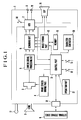
- Fig. 1 is a block diagram showing in outline the arrangement of a video camera system which is arranged as an embodiment of this invention.
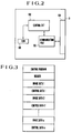
- Fig. 2 is a block diagram showing the arrangement of an external storage device included in the same embodiment of the invention.
- Fig. 3 schematically shows data stored in a ROM shown in Fig. 2.
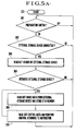
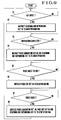
- Fig. 4 is a flow chart showing the operation of a control circuit included in the external storage device of Fig. 2.
- Fig. 5(A) is a flow chart showing in outline the operation of a control part disposed within a camera body.
- Fig. 5(B) is a flow chart showing in detail a part of Fig. 5(A).
- Figs. 1 is a block diagram showing in outline the arrangement of a video camera system which is arranged as an embodiment of this invention.
- Fig. 2 is a block diagram showing the arrangement of an external storage device included in the same embodiment of the invention.
- Fig. 3 schematically shows data stored in a ROM shown in Fig.
- FIG. 7 is a block diagram showing the arrangement of another embodiment of the invention.
- Fig. 8 shows by way of example the arrangement of a music generating circuit, a mixing circuit and a fade-out circuit.
- Fig. 9 is a flow chart showing the operation of the embodiment shown in Fig. 7.
- Fig. 1 is a block diagram showing in outline the arrangement of a video camera system which is arranged according to this invention as an embodiment thereof.
- the illustration includes the body 1 of a VTR-integrated type video camera; a photo-taking lens 2; an image sensor 3; an image sensor driving part 4; a camera signal processing circuit 5; a combining circuit 6 which is arranged to combine a video signal obtained by shooting with other video signals such as a title signal, etc.; a VTR part 7; a video output terminal 8 for outputting the video signal; an external storage device 9 which is connected to the camera body 1; a connection part 10 which is arranged to permit the external storage device 9 to be attached to or detached from the camera body 1 and to make electrical connection between the two; a control part 11 which is arranged to control the external storage device 9, to send and receive data, to control a switch operation and to control a character generator 20, etc.; a preparation switch 12; a control switch 13; a cassette switch 14 which is arranged to detect the mounting of a tape cassette on
- An object image (not shown) obtained by the photo-taking lens 2 is formed on the image sensor 3.
- the image sensor 3 photo-electrically converts this object image into an image signal, which is supplied to the camera signal processing circuit 5.
- the image sensor 3 is arranged to perform a prescribed image sensing action in accordance with a timing pulse signal output from the image sensor driving part 4.
- the camera signal processing circuit 5 performs a given processing action on the image signal and produces a video signal as a result of the action.
- the video signal thus obtained is supplied to the combining circuit 6 to be combined with a title signal, etc. which will be described later.
- the signal thus formed by the combining circuit 6 is supplied to the VTR part 7 to be recorded there. At the time of reproduction, the output of the VTR part 7 is supplied from the video output terminal 8 to an external apparatus such as a TV monitor or the like.
- the sounds obtained by the microphone 17 are recorded by the VTR part 7 either in a predetermined audio track or in an audio recording band along with the above-stated video signal.
- the audio signal is supplied from the audio output terminal 18 to an external apparatus such as a TV monitor or the like.
- the control part 11 operates according to the states of switches 12, 13 and 14, the connection state of the external storage device 9 which is connected to the connection part 10, communication data, etc. and is arranged to transfer data to the image forming part 15, to control the image forming part 15 and to control the character generator 20 for displaying information in the form of characters or the like on the electronic viewfinder (EVF) 19.
- the image forming part 15 is arranged to receive data from the control part 11, to write the received data into the memory 16 and to form a title image signal by reading out the data from the memory 16 in accordance with the instruction of the control part 11.
- the title image signal thus obtained is combined with the video signal, as mentioned above, by the combining circuit 6.
- the connection part 10 is arranged to permit each of external storage devices of varied kinds to be detachably attached thereto as the external storage device 9.
- Fig. 2 shows the arrangement of the external storage device 9 for the purpose of describing a specific embodiment of this invention.
- the illustration includes a ROM 101; a control circuit 102, a serial communication port 103 and a connector 104 which is provided for electrical connection with the camera body 1.
- an instruction is received from the camera body 1 via the connector 104 and the communication port 103, an action is performed in accordance with the instruction.
- data is read out from the ROM 101, and the readout data is sent to the camera body 1 via the communication port 103 and the connector 104.
- Fig. 3 schematically shows by way of example the data contained within the ROM 101 of Fig. 2.
- the head part of the ROM 101 stores a control program for conducting the above-stated communication, interpreting the instruction, reading out data, etc.
- a header part which contains data indicating the kind of the external storage device 9, the leading address of each data contained, etc.
- the header part is followed by image data 1 to n (n: a natural number) and control data 1 to n which are stored at predetermined addresses in the order as shown in Fig. 3.
- the number n of combinations of the image data and the control data stored in each piece of the external storage devices is 10 to 20 or thereabout.
- Fig. 4 is a flow chart showing the operation of the control circuit 102 disposed within the external storage device 9. The operation begins at a step 201. At a step 202: The control circuit 102 first receives a reading address sent from the camera body 1. At a step 203: Data stored at the reading address is sent to the camera body 1, and the flow of operation comes back to the step 202 to repeat the above-stated process.
- Fig. 5(A) is a flow chart showing the operation of the control part 11 which is disposed within the camera body 1.
- a check is made for the state of the preparation switch 12 at a step 301.
- the flow comes to a step 302 if the switch 12 is found in an on-state, or the flow comes back to the step 301 to repeat the check for the state of the switch 12 if the switch 12 is in an off-state.
- a detection terminal or the like which is provided at the connection part 10 is checked for the presence or absence of the external storage device 9. If the device 9 is thus found to be in connection, the flow comes to a step 303. If not, the flow comes back to the step 301 to repeat the same process.
- the header of the external storage device 9 is read out.
- a check is made to find if the external storage device 9 is of an intended kind. If so, the flow comes to a step 305. If not, the flow comes back to the step 301 to repeat the preceding steps.
- One of the "n" number of combinations of image data and control data is selected, and the image data thus selected is read out from the external storage device 9. The image data thus read out is then stored in the memory 16 through the image forming part 15.
- the control data is read out also from the external storage device 9. Applicable parts are controlled one after another according to a control instruction indicated by the control data. After completion of the control, the flow comes back to the step 301 to repeat the above-stated processes.
- Fig. 5(B) is a flow chart showing the details of the steps 305 and 306 of Fig. 5(A).
- the control operation begins through the steps 304 and 305 of Fig. 5(A).
- a reading address is set, within the ROM 101 of the external storage device 9, at the head of the control data selected at the step 305.
- the control data stored at the reading address is read out from the external storage device 9.
- the reading address is advanced by one.
- steps 410 to 421 Each of the data thus read out is regarded as an instruction, and the flow branches to a respective one of steps 430 to 439, 305 and 301 as applicable. If the instruction is found to be not applicable to any of these steps, the flow comes back to the step 402 to make the instruction invalid.
- the flow comes to the step 430 to wait until the control switch 13 is operated. After the switch 13 is operated, the flow comes back to the step 402 to continue the control operation.
- the flow comes to the step 431.
- the image forming part 15 is controlled and caused to supply the title image data which has been stored in the memory 16 at the step 305 of Fig. 5(A) to the combining circuit 6 in such a way as to combine the title image data with the recording signal. After that, the flow comes back to the step 402 to proceed with the control operation.
- the instruction is for ending the title combining process
- the flow comes to the step 432.
- the image forming part 15 is controlled and caused to stop supplying the title image data to the combining circuit 6. After that, the flow comes back to the step 402 to proceed with the control operation.
- the flow comes to the step 433.
- the character generator 20 is controlled and caused to begin to supply a character signal to the combining circuit 6. After that, the flow comes back to the step 402 to continue the control operation.
- the instruction is for ending the character combining process
- the flow comes to the step 434.
- the character generator 20 is controlled and caused to stop supplying the character signal to the combining circuit 6. After that, the flow comes back to the step 402 to continue the control operation.
- the flow comes to the step 435.
- the camera signal processing circuit 5 is controlled in such a way as to fade out the video signal obtained by shooting. After that, the flow comes back to the step 402 to further proceed with the control operation.
- the flow comes to a step 436.
- the camera signal processing circuit 5 is controlled in such a way as to bring the video signal back to its normal state (fade-in). The flow then comes back to the step 402 to further continue the control operation.
- the flow comes to a step 437.
- the VTR part 7 is controlled and caused to start recording. After that, the flow comes back to the step 402 to continue the control operation.
- the instruction is for bringing the operation of the VTR to a stop
- the flow comes to the step 438.
- the recording operation is brought to a stop by controlling the VTR part 7. The flow then comes back to the step 402 to continue the control operation.
- the instruction is for making a check for the tape
- the flow comes to the step 439.
- the state of the cassette switch 14 is detected through the VTR part 7 to find the presence or absence of a cassette tape.
- step 440 If no cassette tape is mounted, the flow comes to a step 440.
- the reading address is advanced by one and the next instruction is made invalid. After that, the flow comes back to the step 402 to further proceed with the control operation.
- the flow comes back to the step 305 to repeat the selection of image data and control data and the control operation from the beginning.
- the instruction is for ending the control, the flow comes back to the step 301 of Fig. 5(A) to terminate the control operation.
- Fig. 6(A) schematically shows a first example of control data (hereinafter referred to as control data 1) which is stored within the ROM of the external storage device 9.
- control data 1 control data 1
- the preparation switch 12 is first operated by the operator. After that, with the external storage device 9 connected to the camera body 1 and the control data 1 selected, the control part 11 proceeds to operate as follows:
- the control part 1 waits until the control switch 13 is operated by the operator.
- the image forming part 15 is controlled and caused to supply the title image data which has been stored to the combining circuit 6.
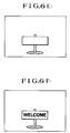
- the title image data is then superimposed, as a title, on the video signal obtained by shooting in a manner as shown in Fig. 6(E).
- the character generator 20 is controlled and caused to begin to supply a character signal to the combining circuit 6.
- Fig. 6(F) an image which overlaps with the title image is combined with the video signal obtained by shooting.
- the control part 11 waits until the control switch 13 is again operated by the operator.
- the image forming part 15 is caused, in accordance with an instruction for ending the title combining action, to stop supplying the title image data to the combining circuit 6.
- the title image ceases to be combined with the video signal obtained by shooting.
- the character generator 20 is caused to stop supplying the character signal. This brings the title and character combining actions to an end. After that, in accordance with a control ending instruction, the flow of operation comes back to the step 301 to end the control operation.
- Fig. 6(B) schematically shows a second example of the control data (hereinafter referred to as control data 2) stored within the ROM of the external storage device 9.
- Control data 2 stored within the ROM of the external storage device 9.
- Programmed processes to be performed according to the control data 2 are as follows:
- the control part 11 proceeds, after the preparation switch 12 is operated by the operator, to carry out the processes according to the control data 2.
- the control part 11 waits until the control switch 13 is operated by the operator.
- a title begins to be combined with the video signal obtained by shooting in response to a title-combining beginning instruction.
- the control part 11 waits until the control switch 13 is again operated by the operator.
- the camera signal processing circuit 5 is controlled and caused, in response to an instruction for a fade-out action, to fade out the video signal obtained by shooting.
- the title inserting process Upon completion of the fade-out process, the title inserting process also comes to an end in response to a title-combining ending instruction. Then, in response to a fade-out canceling instruction, the camera signal processing circuit 5 is controlled and caused to fade in the video signal. After completion of the fade-in, the control operation comes to an end in response to a control ending instruction.
- control processes enable the operator to fade out and fade in the video signal in concordance with the title inserting action by simply operating the control switch 13.
- Fig. 6(C) schematically shows a third example of the control data (hereinafter referred to as control data 3) stored within the ROM of the external storage device 9.
- control data 3 the control data stored within the ROM of the external storage device 9.
- the preparation switch 12 is first operated by the operator. Then, with the external storage device 9 assumed to be connected to the camera body 1 and the control data 3 to be selected, the control part 11 proceeds to carry out processes in accordance with the control data 3 in the following manner:
- the control part 11 waits until the control switch 13 is operated by the operator.
- the VTR part 7 is controlled and caused to begin the recording in response to a VTR starting instruction.
- a title is inserted in the video signal obtained by shooting (a recording video signal) in the same manner as described in the foregoing.
- the control part 11 waits until the control switch 13 is again operated by the operator.
- the VTR part 7 is again controlled to bring its recording action to an end in response to a VTR stopping instruction.
- the title combining process is brought to a stop and the control operation is terminated in response to an instruction for ending the control.
- Fig. 6(D) schematically shows a fourth example of the control data (control data 4) stored within the ROM of the external storage device 9.
- the preparation switch 12 is first operated by the operator in the same manner as in the case of the control data 1, 2 or 3. Then with the external storage device 9 connected to the camera body 1 and the control data 4 selected, the control part 11 carries out processes according to the control data 4 in the following manner:
- the control part 11 waits until the control switch 13 is operated by the operator. After the control switch 13 is operated, a title is inserted into the recording video signal in response to an instruction for starting a title combining action in the same manner as described in the foregoing. Next, another tape checking instruction is given. However, since the tape is mounted in this instance, the control part 11 comes to execute a next instruction. Then, in accordance with another key input waiting instruction, the control part 11 waits until the control switch 13 is again operated by the operator.
- the image forming part 15 is controlled and caused, in response to a title-combining ending instruction, to stop combining the title image data with the video signal. After this, a tape checking instruction is given for the third time. However, the control operation also comes to execute a next instruction. Then, in response to a control ending instruction, the flow of operation comes back to the step 301 to terminate the control operation.
- the control operation comes to execute a next instruction after the first tape checking instruction. Then, in response to the title-combining beginning instruction, the image forming part 15 is controlled and caused to combine stored image data with the recording video signal. At the time of the second tape checking instruction, the operation also comes to execute the next instruction which is the title-combining ending instruction. In accordance with it, the image forming part 15 is controlled to bring the title image data combining action to a stop. Further, when the third tape checking instruction is given, the control operation likewise comes to execute a next instruction. Then, in accordance with a control repeating instruction, the flow of operation comes back to the step 305 to repeat the image data selecting and controlling actions from the beginning.
- the above-stated processes according to the control data 4 enable the operator to start and stop the title image combining action by simply turning the control switch 13 on with the tape cassette mounted on the VTR part 7. In a case where no tape cassette is mounted, the start and stop of the title image combining action are automatically carried out. In the latter case, with the system programmed to spend a given period of time in detecting the mounted state of the tape cassette in accordance with the tape checking instruction, the title corresponding to the image data selected is displayed just for a given period of time at the EVF (electronic viewfinder) 19. This enables the operator to know what kind of image data is stored. Further, with the cassette mounted after the confirmation, the title image confirmed can be smoothly combined with the video signal by returning the control operation back to the step 305.
- EVF electronic viewfinder
- control data has been described in the foregoing only for the control data 1 to 4 shown in Figs. 6(A) to 6(D).
- the control data may be arranged to include the fade-in and fade-out of sounds, changeover between color- and monochromatic-shooting modes at the camera signal processing circuit 5, shutter speed change-over at the image sensor driving part 4, etc.
- the camera part and the VTR part can be controlled with apposite timing after insertion of a title image by including these functions in the control data.
- a signal recording system can be arranged to be capable of recording signals of varied kinds with an extremely simplified operation.
- Fig. 7 is a block diagram showing in outline the arrangement of another embodiment of the invention.
- the illustration includes a music generating circuit 60; an input terminal 62 for an audio signal; a mixing circuit 64 which is arranged to mix a music signal generated by the music generating circuit 60 with the audio signal supplied to the input terminal 62; an input terminal 66 for a video signal; a fade-out circuit 68 which is arranged to fade-out the output of the mixing circuit 64 and the video signal of the video signal input terminal 66 in accordance with an external control signal; a recording and reproducing circuit 70 which is capable of recording and reproducing sounds and images; a combination 72 of an external monitor and a speaker; a control circuit 74 (a microcomputer) which controls the music generating circuit 60, the fade-out circuit 68 and the recording and reproducing circuit 70; and an input terminal 76 for a key signal which instructs the control circuit 74 to begin to perform a prescribed operation.
- a control circuit 74 a microcomputer
- the music generating circuit 60 supplies to the control circuit 74 an advance notice signal which notifies in advance the end of music at a point of time near to the end of the music generated.
- the recording and reproducing circuit 70 supplies to the control circuit 74 a preparation completion signal which indicates completion of preparation for the recording or reproduction.
- Fig. 8 shows by way of example the basic circuit arrangement of the music generating circuit 60, the mixing circuit 64 and the fade-out circuit 68.
- the music generating circuit 60 is, for example, composed of a music IC.
- the mixing circuit 64 is arranged to permit adjustment of a mixing ratio by means of an external volume control part.
- the fade-out circuit 68 is arranged to gradually attenuate, in accordance with a control signal from the control circuit 74, the video and audio signals being supplied to the recording and reproducing circuit 70.
- Fig. 9 is a flow chart, the operation of the system shown in Fig. 7 is described as follows: At a step S1: A check is made to find if a key signal for instructions to start the recording or reproduction is supplied from the input terminal 76 to the control circuit 74. If so, the flow of operation comes to a step S2. At the step S2: The control circuit 74 supplies a signal to the recording and reproducing circuit 70 to prepare for recording or reproduction. At a step S3: A check is made for a preparation completion signal from the recording and reproducing circuit 70. Step S4: In response to the preparation completion signal, a control signal is supplied to the music generating circuit 60 and the recording and reproducing circuit 70 for the start of their operations. This causes the music generating circuit 60 to generate music and, at the same time, the recording and reproducing circuit 70 to begin the recording or reproduction.
- the mixing circuit 64 then mixes the music signal output from the music generating circuit 60 and the audio signal supplied to the input terminal 62. A mixture output thus obtained is applied via the fade-out circuit 68 to the recording and reproducing circuit 70. At this point of time, the fade-out circuit 68 is in a signal passing state.
- Step S5 When the music generated by the music generating circuit 60 approaches an end and thus comes at a point, say, 10 seconds before the end, the music generating circuit 60 supplies to the control circuit 74 a signal giving an advance notice of the end of the music generation.
- Step 6 In response to the advance notice signal from the music generating circuit 60, the control circuit 74 sends a control signal to the fade-out circuit 68. The control signal causes the fade-out circuit 68 to fade out the video signal from the input terminal 66 and the output of the mixing circuit 64.
- Step S7 When the music comes to an end, the music generating circuit 60 sends a music end signal to the control circuit 74, informing the latter of the end of the music.
- Step S8 In response to the music end signal, the control circuit 74 sends a control signal to the music generating circuit 60 and the fade-out circuit 68 to instruct them to stop operating. Further, a control signal is sent also to the recording and reproducing circuit 70 to instruct it to stop the recording or reproduction. This brings the operation of the music generating circuit 60 and that of the recording and reproducing circuit 70 to a stop.
- the embodiment which is arranged as shown in Figs. 7, 8 and 9 permits the operator to simultaneously start the recording or reproduction of images and music by a single operation on the system. Further, since the music can be completed for each scene, a plurality of scenes can be neatly connected to each other without disrupting the music of each scene.
Description
- This invention relates to a signal recording system and more particularly to a method for determining the timing of control over the operation of a recording apparatus.
- Heretofore, many systems have been proposed for combining a recording video signal with the images of characters, symbols, specific pictures, etc., for example, by superimposing them on the video signal for the purpose of enhancing the image effect in recording the video signal which is obtained by a video camera or in recording an audio signal obtained along with the video signal.
- First, in respect of the method of combining a video signal obtained by shooting with some other image signal, a system which uses a so-called character generator is, for example, employed in many cases. This system comprises a pattern ROM (read-only memory) which stores therein such patterns as characters, symbols, etc. that can be displayed; registers which store therein the kinds of characters to be displayed for all display positions; and a reading part which is arranged to read out the contents of the pattern ROM corresponding to the contents of the above-stated registers in accordance with horizontal and vertical synchronizing signals and to use the read-out contents to be combined with a video signal. In cases where the characters are to be displayed, the display is made by writing the kinds of the displayed characters into the registers provided for applicable display positions.
- Another example of systems of this kind is arranged to analog-to-digital (A/D) convert the signal obtained by shooting into a digital signal of 1 to several bits; to store the digital signal in a memory for every one of the display picture elements; to read out the stored digital signal from the memory in accordance with horizontal and vertical synchronizing signals; and to use the read-out signal to be combined with a video signal obtained separately by shooting.
- A further example of known systems is arranged to include a graphic memory which corresponds to each of the picture elements of an image plane, a microcomputer which writes into the graphic memory data to be displayed and a reading circuit which reads out the contents of the graphic memory in accordance with horizontal and vertical synchronizing signals; and to use the read-out contents to be combined with a video signal obtained by shooting.
- However, the insertion of predetermined images into a signal obtained by shooting as mentioned above necessitates not only the use of various equipments for the above-stated processes and also that of connection lines for connection with these various equipments. Therefore, it is extremely difficult to have them at the homes of ordinary people who are not in this business.
- Further, in cases where the start and stop of recording or reproduction of images are to be controlled simultaneously with the start and stop of generation of music, separate apparatuses such as a music-generating apparatus and an image recording/reproducing apparatus must be manually operated at the same time since there is no simple device for simultaneous control over images and music.
- Simultaneous manual operations on two separate apparatuses with apposite timing are not only difficult but also quite troublesome. As a result, the parts of music are not neatly connected. The timing of an end of music must be borne in mind during the process of image recording or reproduction. It has been difficult to attain any satisfactory result of such a manual operation.
- Meanwhile, there has been proposed another system which is arranged as follows: An external storage device for storing various video and audio data, etc. is arranged to be removably attachable to the above-stated video signal recording apparatus. A video signal obtained by shooting and an audio signal obtained by collecting sounds are recorded by either combining or replacing them with the video and audio data read out from the external storage device. The systems of this kind have been disclosed, for example, in U.S. Patent Applications Serial No. 619,768, filed on Nov. 29, 1990 and Serial No. 633,974, filed on Dec. 26, 1990. The system of this kind is highly advantageous in that it permits recording many diverse signals without increasing its size.
- However, the quality of a work obtained by such a system greatly depends on the timing of recording the video and audio data read out from the external storage device. For example, an image of a title or the like read out from the external storage device is inserted, during a given period of time from the start of shooting, into a picture obtained by shooting and, after the lapse of the given period of time, the scene of the picture is changed to another scene by canceling the insertion of the title at the same time. In this instance, the quality of the work would be degraded if the title insertion canceling timing disagrees with the change-over timing of the scene.
- Meanwhile, it is not easy for ordinary users to operate the recording apparatus at apposite timing while selecting and obtaining an image from among other images stored in the external storage device, because it requires a certain degree of skill. Besides, the difficulty of this operation increases if it involves other functions, such as character generation, fade-in and fade-out, etc.
- In other words, the above-stated system should be improved in respect of operability.
- US-A-4899229 describes a video information editing system in which video information already recorded on a video tape and defining one frame can, as occasion demands, be written into a field memory. The content of the field memory can then be stored in an external memory device comprising a floppy disk or magnetic tape. Selected frames stored in the external memory device may be displayed on a television monitor or may be copied to a video tape by operation of a switch. As another possibility, an index for locations of selected frames on a video tape may be stored in the external memory device to enable parts of the already recorded video tape to be accessed in accordance with the information stored in the index.
- EP-A-0255108 describes a program preset control circuit which allows the starting time and period of recording of a video tape recorder to be controlled by a signal supplied by the broadcasting station. The circuit includes a preset program coincidence determining circuit which compares an incoming program code from the broadcasting station with a stored starting time and outputs a coincidence signal to enable recording to start when the incoming program code agrees with the stored starting time.
- According to the present invention, there is provided a recording apparatus in accordance with
claim 1. - An embodiment of this invention provides a recording apparatus which is arranged to permit simple recording operations on diverse signals without the complexity of operation required by the conventional signal recording system.
- An external storage device which is attachable to and detachable from the recording apparatus may be provided as the storage means. As another possibility a microcomputer may be provided as the storage means.
- In an embodiment, the apparatus comprises: video input means for receiving a video signal; memory means for storing control information and audio information; audio generating means for generating an audio signal corresponding to the audio information; recording means for recording on a recording medium the video signal and the audio signal; and control means for controlling an operation of the audio generating means and a recording operation of the recording means in accordance with the control information read out from the memory means so providing a signal recording system which is arranged to permit synchronization of image recording and sound generation with each other by a simple operation.
- The above and other objects and features of the invention will become apparent from the following detailed description of embodiments thereof taken in conjunction with the accompanying drawings.
- Fig. 1 is a block diagram showing in outline the arrangement of a video camera system which is arranged as an embodiment of this invention. Fig. 2 is a block diagram showing the arrangement of an external storage device included in the same embodiment of the invention. Fig. 3 schematically shows data stored in a ROM shown in Fig. 2. Fig. 4 is a flow chart showing the operation of a control circuit included in the external storage device of Fig. 2. Fig. 5(A) is a flow chart showing in outline the operation of a control part disposed within a camera body. Fig. 5(B) is a flow chart showing in detail a part of Fig. 5(A). Figs. 6(A), 6(B), 6(C) and 6(D) schematically show examples of control data of Fig. 3. Figs. 6(E) and 6(F) show operations performed according to the control data. Fig. 7 is a block diagram showing the arrangement of another embodiment of the invention. Fig. 8 shows by way of example the arrangement of a music generating circuit, a mixing circuit and a fade-out circuit. Fig. 9 is a flow chart showing the operation of the embodiment shown in Fig. 7.
- The following describes the details of this invention through embodiments thereof:
- Fig. 1 is a block diagram showing in outline the arrangement of a video camera system which is arranged according to this invention as an embodiment thereof. The illustration includes the
body 1 of a VTR-integrated type video camera; a photo-taking lens 2; animage sensor 3; an imagesensor driving part 4; a camerasignal processing circuit 5; a combiningcircuit 6 which is arranged to combine a video signal obtained by shooting with other video signals such as a title signal, etc.; a VTR part 7; avideo output terminal 8 for outputting the video signal; anexternal storage device 9 which is connected to thecamera body 1; aconnection part 10 which is arranged to permit theexternal storage device 9 to be attached to or detached from thecamera body 1 and to make electrical connection between the two; a control part 11 which is arranged to control theexternal storage device 9, to send and receive data, to control a switch operation and to control acharacter generator 20, etc.; apreparation switch 12; acontrol switch 13; a cassette switch 14 which is arranged to detect the mounting of a tape cassette on the VTR part 7; animage forming part 15 which is arranged to form a title signal; a memory 16 which is arranged to hold image data included in the title data read-out from theexternal storage device 9 and to permit writing and reading actions thereon; amicrophone 17 which is mounted on a part of thecamera body 1 and is arranged to record sounds; anaudio output terminal 18; an electronic viewfinder 19 (EVF) which is arranged to display images obtained during recording and reproducing operations and to display also character information about the state of operation; thecharacter generator 20; and anoperation part 21 which includes a ten-key part, plus and minus keys, etc. - An object image (not shown) obtained by the photo-taking
lens 2 is formed on theimage sensor 3. Theimage sensor 3 photo-electrically converts this object image into an image signal, which is supplied to the camerasignal processing circuit 5. Theimage sensor 3 is arranged to perform a prescribed image sensing action in accordance with a timing pulse signal output from the imagesensor driving part 4. The camerasignal processing circuit 5 performs a given processing action on the image signal and produces a video signal as a result of the action. The video signal thus obtained is supplied to the combiningcircuit 6 to be combined with a title signal, etc. which will be described later. The signal thus formed by the combiningcircuit 6 is supplied to the VTR part 7 to be recorded there. At the time of reproduction, the output of the VTR part 7 is supplied from thevideo output terminal 8 to an external apparatus such as a TV monitor or the like. - Meanwhile, the sounds obtained by the
microphone 17 are recorded by the VTR part 7 either in a predetermined audio track or in an audio recording band along with the above-stated video signal. At the time of reproduction, the audio signal is supplied from theaudio output terminal 18 to an external apparatus such as a TV monitor or the like. - The control part 11 operates according to the states of
switches external storage device 9 which is connected to theconnection part 10, communication data, etc. and is arranged to transfer data to theimage forming part 15, to control theimage forming part 15 and to control thecharacter generator 20 for displaying information in the form of characters or the like on the electronic viewfinder (EVF) 19. Theimage forming part 15 is arranged to receive data from the control part 11, to write the received data into the memory 16 and to form a title image signal by reading out the data from the memory 16 in accordance with the instruction of the control part 11. The title image signal thus obtained is combined with the video signal, as mentioned above, by the combiningcircuit 6. Further, theconnection part 10 is arranged to permit each of external storage devices of varied kinds to be detachably attached thereto as theexternal storage device 9. - Fig. 2 shows the arrangement of the
external storage device 9 for the purpose of describing a specific embodiment of this invention. The illustration includes aROM 101; acontrol circuit 102, aserial communication port 103 and aconnector 104 which is provided for electrical connection with thecamera body 1. When an instruction is received from thecamera body 1 via theconnector 104 and thecommunication port 103, an action is performed in accordance with the instruction. For example, data is read out from theROM 101, and the readout data is sent to thecamera body 1 via thecommunication port 103 and theconnector 104. - Fig. 3 schematically shows by way of example the data contained within the
ROM 101 of Fig. 2. As shown, the head part of theROM 101 stores a control program for conducting the above-stated communication, interpreting the instruction, reading out data, etc. Following the control program, there is provided a header part which contains data indicating the kind of theexternal storage device 9, the leading address of each data contained, etc. The header part is followed byimage data 1 to n (n: a natural number) andcontrol data 1 to n which are stored at predetermined addresses in the order as shown in Fig. 3. Further, the number n of combinations of the image data and the control data stored in each piece of the external storage devices is 10 to 20 or thereabout. - Fig. 4 is a flow chart showing the operation of the
control circuit 102 disposed within theexternal storage device 9. The operation begins at astep 201. At a step 202: Thecontrol circuit 102 first receives a reading address sent from thecamera body 1. At a step 203: Data stored at the reading address is sent to thecamera body 1, and the flow of operation comes back to thestep 202 to repeat the above-stated process. - Fig. 5(A) is a flow chart showing the operation of the control part 11 which is disposed within the
camera body 1. Referring to Fig. 5(A), a check is made for the state of thepreparation switch 12 at astep 301. The flow comes to astep 302 if theswitch 12 is found in an on-state, or the flow comes back to thestep 301 to repeat the check for the state of theswitch 12 if theswitch 12 is in an off-state. At the step 302: A detection terminal or the like which is provided at theconnection part 10 is checked for the presence or absence of theexternal storage device 9. If thedevice 9 is thus found to be in connection, the flow comes to astep 303. If not, the flow comes back to thestep 301 to repeat the same process. At the step 303: The header of theexternal storage device 9 is read out. At a step 304: A check is made to find if theexternal storage device 9 is of an intended kind. If so, the flow comes to astep 305. If not, the flow comes back to thestep 301 to repeat the preceding steps. At the step 305: One of the "n" number of combinations of image data and control data is selected, and the image data thus selected is read out from theexternal storage device 9. The image data thus read out is then stored in the memory 16 through theimage forming part 15. At a step 306: The control data is read out also from theexternal storage device 9. Applicable parts are controlled one after another according to a control instruction indicated by the control data. After completion of the control, the flow comes back to thestep 301 to repeat the above-stated processes. - Fig. 5(B) is a flow chart showing the details of the
steps steps ROM 101 of theexternal storage device 9, at the head of the control data selected at thestep 305. At a step 402: the control data stored at the reading address is read out from theexternal storage device 9. At a step 403: The reading address is advanced by one. Atsteps 410 to 421: Each of the data thus read out is regarded as an instruction, and the flow branches to a respective one ofsteps 430 to 439, 305 and 301 as applicable. If the instruction is found to be not applicable to any of these steps, the flow comes back to thestep 402 to make the instruction invalid. - If the above-stated instruction is an instruction for waiting for a key input, the flow comes to the
step 430 to wait until thecontrol switch 13 is operated. After theswitch 13 is operated, the flow comes back to thestep 402 to continue the control operation. - In the event of an instruction for starting a title combining action, the flow comes to the
step 431. At the step 431: Theimage forming part 15 is controlled and caused to supply the title image data which has been stored in the memory 16 at thestep 305 of Fig. 5(A) to the combiningcircuit 6 in such a way as to combine the title image data with the recording signal. After that, the flow comes back to thestep 402 to proceed with the control operation. If the instruction is for ending the title combining process, the flow comes to thestep 432. At the step 432: Theimage forming part 15 is controlled and caused to stop supplying the title image data to the combiningcircuit 6. After that, the flow comes back to thestep 402 to proceed with the control operation. - In a case where the instruction is for starting a character combining process, the flow comes to the
step 433. At the step 433: Thecharacter generator 20 is controlled and caused to begin to supply a character signal to the combiningcircuit 6. After that, the flow comes back to thestep 402 to continue the control operation. If the instruction is for ending the character combining process, the flow comes to thestep 434. At the step 434: Thecharacter generator 20 is controlled and caused to stop supplying the character signal to the combiningcircuit 6. After that, the flow comes back to thestep 402 to continue the control operation. - In the event of an instruction for a fade-out action, the flow comes to the
step 435. At the step 435: The camerasignal processing circuit 5 is controlled in such a way as to fade out the video signal obtained by shooting. After that, the flow comes back to thestep 402 to further proceed with the control operation. In a case where the instruction is for canceling the fade-out action, the flow comes to astep 436. At the step 436: The camerasignal processing circuit 5 is controlled in such a way as to bring the video signal back to its normal state (fade-in). The flow then comes back to thestep 402 to further continue the control operation. - In a case where the instruction is for starting the VTR, the flow comes to a
step 437. At the step 437: The VTR part 7 is controlled and caused to start recording. After that, the flow comes back to thestep 402 to continue the control operation. In a case where the instruction is for bringing the operation of the VTR to a stop, the flow comes to thestep 438. At the step 438: The recording operation is brought to a stop by controlling the VTR part 7. The flow then comes back to thestep 402 to continue the control operation. If the instruction is for making a check for the tape, the flow comes to thestep 439. At the step 439: The state of the cassette switch 14 is detected through the VTR part 7 to find the presence or absence of a cassette tape. If no cassette tape is mounted, the flow comes to astep 440. At the step 440: The reading address is advanced by one and the next instruction is made invalid. After that, the flow comes back to thestep 402 to further proceed with the control operation. In the event of a control repeating instruction, the flow comes back to thestep 305 to repeat the selection of image data and control data and the control operation from the beginning. In a case where the instruction is for ending the control, the flow comes back to thestep 301 of Fig. 5(A) to terminate the control operation. - Fig. 6(A) schematically shows a first example of control data (hereinafter referred to as control data 1) which is stored within the ROM of the
external storage device 9. The following describes programmed processes performed in accordance with thecontrol data 1. Thepreparation switch 12 is first operated by the operator. After that, with theexternal storage device 9 connected to thecamera body 1 and thecontrol data 1 selected, the control part 11 proceeds to operate as follows: - First, in accordance with an instruction for waiting for a key input, the
control part 1 waits until thecontrol switch 13 is operated by the operator. When thecontrol switch 13 is operated, theimage forming part 15 is controlled and caused to supply the title image data which has been stored to the combiningcircuit 6. The title image data is then superimposed, as a title, on the video signal obtained by shooting in a manner as shown in Fig. 6(E). At the same time, in accordance with an instruction for a start of a character combining action, thecharacter generator 20 is controlled and caused to begin to supply a character signal to the combiningcircuit 6. Then, as shown in Fig. 6(F), an image which overlaps with the title image is combined with the video signal obtained by shooting. Next, in accordance with another key input waiting instruction, the control part 11 waits until thecontrol switch 13 is again operated by the operator. When thecontrol switch 13 is operated again, theimage forming part 15 is caused, in accordance with an instruction for ending the title combining action, to stop supplying the title image data to the combiningcircuit 6. Then the title image ceases to be combined with the video signal obtained by shooting. Further, in accordance with an instruction for ending the character combining action, thecharacter generator 20 is caused to stop supplying the character signal. This brings the title and character combining actions to an end. After that, in accordance with a control ending instruction, the flow of operation comes back to thestep 301 to end the control operation. - The above-stated processes enable the operator to synchronously insert the title and characters by simply operating the
control switch 13. - Fig. 6(B) schematically shows a second example of the control data (hereinafter referred to as control data 2) stored within the ROM of the
external storage device 9. Programmed processes to be performed according to thecontrol data 2 are as follows: - With the
external storage device 9 connected to thecamera body 1 and with thecontrol data 2 selected, the control part 11 proceeds, after thepreparation switch 12 is operated by the operator, to carry out the processes according to thecontrol data 2. First, in accordance with a key input waiting instruction, the control part 11 waits until thecontrol switch 13 is operated by the operator. When thecontrol switch 13 is operated, a title begins to be combined with the video signal obtained by shooting in response to a title-combining beginning instruction. Then, in accordance with another key input waiting instruction, the control part 11 waits until thecontrol switch 13 is again operated by the operator. When thecontrol switch 13 is again operated, the camerasignal processing circuit 5 is controlled and caused, in response to an instruction for a fade-out action, to fade out the video signal obtained by shooting. Upon completion of the fade-out process, the title inserting process also comes to an end in response to a title-combining ending instruction. Then, in response to a fade-out canceling instruction, the camerasignal processing circuit 5 is controlled and caused to fade in the video signal. After completion of the fade-in, the control operation comes to an end in response to a control ending instruction. - The above-stated control processes enable the operator to fade out and fade in the video signal in concordance with the title inserting action by simply operating the
control switch 13. - Fig. 6(C) schematically shows a third example of the control data (hereinafter referred to as control data 3) stored within the ROM of the
external storage device 9. In the same manner as the processes described in the foregoing, thepreparation switch 12 is first operated by the operator. Then, with theexternal storage device 9 assumed to be connected to thecamera body 1 and thecontrol data 3 to be selected, the control part 11 proceeds to carry out processes in accordance with thecontrol data 3 in the following manner: - First, in accordance with a key input waiting instruction, the control part 11 waits until the
control switch 13 is operated by the operator. When thecontrol switch 13 is operated, the VTR part 7 is controlled and caused to begin the recording in response to a VTR starting instruction. Then, in response to an instruction for starting a title combining action, a title is inserted in the video signal obtained by shooting (a recording video signal) in the same manner as described in the foregoing. After that, in accordance with another key input waiting instruction, the control part 11 waits until thecontrol switch 13 is again operated by the operator. When thecontrol switch 13 is again operated, the VTR part 7 is again controlled to bring its recording action to an end in response to a VTR stopping instruction. Then, in response to an instruction for ending the title combining process, the title combining process is brought to a stop and the control operation is terminated in response to an instruction for ending the control. - The above-stated processes enable the operator to have the start or stopping timing of recording perfectly in concordance with the title image combining timing.
- Fig. 6(D) schematically shows a fourth example of the control data (control data 4) stored within the ROM of the
external storage device 9. Thepreparation switch 12 is first operated by the operator in the same manner as in the case of thecontrol data external storage device 9 connected to thecamera body 1 and thecontrol data 4 selected, the control part 11 carries out processes according to thecontrol data 4 in the following manner: - In a case where a tape cassette is detected to be mounted on the VTR part 7 in response to a first instruction for making a check for the tape. The in accordance with a key input waiting instruction, the control part 11 waits until the
control switch 13 is operated by the operator. After thecontrol switch 13 is operated, a title is inserted into the recording video signal in response to an instruction for starting a title combining action in the same manner as described in the foregoing. Next, another tape checking instruction is given. However, since the tape is mounted in this instance, the control part 11 comes to execute a next instruction. Then, in accordance with another key input waiting instruction, the control part 11 waits until thecontrol switch 13 is again operated by the operator. After thecontrol switch 13 is again operated, theimage forming part 15 is controlled and caused, in response to a title-combining ending instruction, to stop combining the title image data with the video signal. After this, a tape checking instruction is given for the third time. However, the control operation also comes to execute a next instruction. Then, in response to a control ending instruction, the flow of operation comes back to thestep 301 to terminate the control operation. - In a case where no tape cassette is mounted on the VTR part 7, the control operation comes to execute a next instruction after the first tape checking instruction. Then, in response to the title-combining beginning instruction, the
image forming part 15 is controlled and caused to combine stored image data with the recording video signal. At the time of the second tape checking instruction, the operation also comes to execute the next instruction which is the title-combining ending instruction. In accordance with it, theimage forming part 15 is controlled to bring the title image data combining action to a stop. Further, when the third tape checking instruction is given, the control operation likewise comes to execute a next instruction. Then, in accordance with a control repeating instruction, the flow of operation comes back to thestep 305 to repeat the image data selecting and controlling actions from the beginning. - The above-stated processes according to the
control data 4 enable the operator to start and stop the title image combining action by simply turning thecontrol switch 13 on with the tape cassette mounted on the VTR part 7. In a case where no tape cassette is mounted, the start and stop of the title image combining action are automatically carried out. In the latter case, with the system programmed to spend a given period of time in detecting the mounted state of the tape cassette in accordance with the tape checking instruction, the title corresponding to the image data selected is displayed just for a given period of time at the EVF (electronic viewfinder) 19. This enables the operator to know what kind of image data is stored. Further, with the cassette mounted after the confirmation, the title image confirmed can be smoothly combined with the video signal by returning the control operation back to thestep 305. - The functions of the control data have been described in the foregoing only for the
control data 1 to 4 shown in Figs. 6(A) to 6(D). However, functions of other diverse kinds are conceivable. For example, the control data may be arranged to include the fade-in and fade-out of sounds, changeover between color- and monochromatic-shooting modes at the camerasignal processing circuit 5, shutter speed change-over at the imagesensor driving part 4, etc. The camera part and the VTR part can be controlled with apposite timing after insertion of a title image by including these functions in the control data. - In accordance with this invention, as described in the foregoing, a signal recording system can be arranged to be capable of recording signals of varied kinds with an extremely simplified operation.
- Fig. 7 is a block diagram showing in outline the arrangement of another embodiment of the invention. The illustration includes a
music generating circuit 60; aninput terminal 62 for an audio signal; a mixingcircuit 64 which is arranged to mix a music signal generated by themusic generating circuit 60 with the audio signal supplied to theinput terminal 62; aninput terminal 66 for a video signal; a fade-out circuit 68 which is arranged to fade-out the output of the mixingcircuit 64 and the video signal of the videosignal input terminal 66 in accordance with an external control signal; a recording and reproducingcircuit 70 which is capable of recording and reproducing sounds and images; acombination 72 of an external monitor and a speaker; a control circuit 74 (a microcomputer) which controls themusic generating circuit 60, the fade-out circuit 68 and the recording and reproducingcircuit 70; and aninput terminal 76 for a key signal which instructs thecontrol circuit 74 to begin to perform a prescribed operation. - The
music generating circuit 60 supplies to thecontrol circuit 74 an advance notice signal which notifies in advance the end of music at a point of time near to the end of the music generated. The recording and reproducingcircuit 70 supplies to the control circuit 74 a preparation completion signal which indicates completion of preparation for the recording or reproduction. - Fig. 8 shows by way of example the basic circuit arrangement of the
music generating circuit 60, the mixingcircuit 64 and the fade-out circuit 68. Themusic generating circuit 60 is, for example, composed of a music IC. The mixingcircuit 64 is arranged to permit adjustment of a mixing ratio by means of an external volume control part. The fade-out circuit 68 is arranged to gradually attenuate, in accordance with a control signal from thecontrol circuit 74, the video and audio signals being supplied to the recording and reproducingcircuit 70. - Referring to Fig. 9 which is a flow chart, the operation of the system shown in Fig. 7 is described as follows: At a step S1: A check is made to find if a key signal for instructions to start the recording or reproduction is supplied from the
input terminal 76 to thecontrol circuit 74. If so, the flow of operation comes to a step S2. At the step S2: Thecontrol circuit 74 supplies a signal to the recording and reproducingcircuit 70 to prepare for recording or reproduction. At a step S3: A check is made for a preparation completion signal from the recording and reproducingcircuit 70. Step S4: In response to the preparation completion signal, a control signal is supplied to themusic generating circuit 60 and the recording and reproducingcircuit 70 for the start of their operations. This causes themusic generating circuit 60 to generate music and, at the same time, the recording and reproducingcircuit 70 to begin the recording or reproduction. - The mixing
circuit 64 then mixes the music signal output from themusic generating circuit 60 and the audio signal supplied to theinput terminal 62. A mixture output thus obtained is applied via the fade-out circuit 68 to the recording and reproducingcircuit 70. At this point of time, the fade-out circuit 68 is in a signal passing state. - Step S5: When the music generated by the
music generating circuit 60 approaches an end and thus comes at a point, say, 10 seconds before the end, themusic generating circuit 60 supplies to the control circuit 74 a signal giving an advance notice of the end of the music generation. Step 6: In response to the advance notice signal from themusic generating circuit 60, thecontrol circuit 74 sends a control signal to the fade-out circuit 68. The control signal causes the fade-out circuit 68 to fade out the video signal from theinput terminal 66 and the output of the mixingcircuit 64. Step S7: When the music comes to an end, themusic generating circuit 60 sends a music end signal to thecontrol circuit 74, informing the latter of the end of the music. Step S8: In response to the music end signal, thecontrol circuit 74 sends a control signal to themusic generating circuit 60 and the fade-out circuit 68 to instruct them to stop operating. Further, a control signal is sent also to the recording and reproducingcircuit 70 to instruct it to stop the recording or reproduction. This brings the operation of themusic generating circuit 60 and that of the recording and reproducingcircuit 70 to a stop. - As apparent from the description given above, the embodiment which is arranged as shown in Figs. 7, 8 and 9 permits the operator to simultaneously start the recording or reproduction of images and music by a single operation on the system. Further, since the music can be completed for each scene, a plurality of scenes can be neatly connected to each other without disrupting the music of each scene.
Claims (21)
- A recording apparatus comprising a recording means (7;70) for recording an information signal on a recording medium, control means (11,76) for controlling a recording operation of said recording means and storage means (9;74) arranged to store a signal comprising video and/or audio information, characterised in that the storage means (9;70) is also arranged to store control information indicating a start and an end timing for recording by the recording means, combining means (6;64,68) are provided for combining another signal comprising video and/or audio information with the signal stored by the storage means and the control means is arranged to control the start and end of recording by the recording means (7;70) of a signal output from the combining means (6;64,68) in response to said control information read out from the storage means (9;74).
- Apparatus according to claim 1, wherein the storage means is a storage device (9) external to the body (1) of the recording apparatus, the external storage device (9) being attachable to and detachable from the recording apparatus.
- Apparatus according to claim 1 or 2, wherein a microcomputer (74) is provided as the storage means.
- Apparatus according to any one of the preceding claims, wherein generating means (2,3,5 or 17 or 20 or 60) are provided for generating an information signal for recording by the recording means (7,70), the storage means stores control information for controlling starting and stopping of the generating of the information signal by the generating means and the control means (11,74) is adapted to control starting and stopping of the generation of the information signal by the generating means.
- Apparatus according to claim 4, wherein said information signal includes a video signal, wherein the generating means (2,3,5) includes a means for fading in or fading out a video signal to be recorded by the recording means, and wherein said control means is adapted to control said fade circuit.
- Apparatus according to claim 4 or 5, wherein the information signal includes a video signal, wherein the generating means (2,3,5 or 20) includes a video camera, said combining means comprises a combining circuit (6) of the generating means adapted to combine a video signal produced by said video camera with another video signal, and wherein said storage means (9) stores the control information for controlling starting and stopping of a combining operation by said combining circuit, said control means (11) being adapted to control the starting and stopping of a combining operation by said combining circuit on the basis of the control information from said storage means (9).
- Apparatus according to claim 6, wherein the combining circuit (6) is adapted to combine the input information signal and the information signal stored in the storage means, the recording means (7) being adapted to record the combined signal from the combining circuit (6).
- Apparatus according to any one of claims 1 to 3, wherein the recording means (7) is adapted to record a first video signal.
- Apparatus according to claim 8, wherein the storage means (9) stores a second video signal.
- Apparatus according to claim 9, wherein said first video signal includes a moving image signal and said second video signal includes at least one of a still image signal and a character signal.
- Apparatus according to claim 9 or 10, further comprising superimposing means for superimposing the second video signal on the input video signal.
- Apparatus according to claim 11, wherein said storage means (9) stores control information for controlling starting and stopping of the superimposing operation of said superimposing means and wherein said control means (11) is adapted to control starting and stopping of the superimposing operation of said superimposing means on the basis of the control information from the storage means (9).
- Apparatus according to claim 9 or 10, further comprising combining means (11,5) for combining the input video signal and said second video signal.
- Apparatus according to claim 13, wherein said storage means (9) stores the control information for controlling starting and stopping of a combining operation of the combining means (11,5) and wherein said control means (11) is adapted to control starting and stopping of a combining operation of said combining means (11,5) on the basis of the control information from the storage means (9).
- Apparatus according to any one of claims 8 to 14, further comprising means (11,5 or 68) for fading-in or fading-out a signal to be recorded by the recording means (7,70), the control means (11) being adapted to control fading-in and fading-out by said fading means (11,5 or 68).
- Apparatus according to any one of claims 8 to 15, further comprising a video camera for generating said first video signal.
- Apparatus according to claim 1, further comprising first generating means (3,5) for generating a first video signal, second generating means (20) for generating a second video signal, and combining means (6) for combining the video signals to produce a combined video signal, the recording means (7) being adapted to record a combined video signal produced by combining means (6) and the control means (11) being adapted to control operation of the recording means (7) and the combining means (6) in accordance with control information read out from the storage means (9).
- Apparatus according to claim 17, wherein said control means (11) is adapted to synchronize the timing of one of the starting and stopping of combining by the combining means (6) with the timing of one of the starting and stopping of recording by the recording means (7).
- Apparatus according to claim 17, wherein the information signal stored by the storage means(9) is a video signal and third generating means (15) are provided for generating a third video signal in accordance with said video information read out from said storage means (9), the combining means (6) being adapted to combine the first, second and third video signals to produce a combined video signal, the control means (11) being adapted to control combining of the second video signal and combining of the third video signal in response to control information from the storage means (9).
- Apparatus according to claim 17, 18 or 19, further comprising means (5) for fading in and out a video signal output from the combining means (6), the recording means (7) being adapted to record a video signal from the fading means (5) and the control means (11) being adapted to control the combining means (6) and the fading means (5) in accordance with control information read out from the storage means (9).
- Apparatus according to claim 1, further comprising video input means (66) for receiving a video signal forming the information signal, audio generating means (60) for generating an audio signal in accordance with audio information stored by the storage means (76), the control means (76) being adapted to control the audio generating means (60) and recording of the video and audio signals by the recording means (70) in accordance with control information read out from the memory means (76).
Priority Applications (1)
| Application Number | Priority Date | Filing Date | Title |
|---|---|---|---|
| EP95201089A EP0667609B1 (en) | 1990-03-09 | 1991-03-07 | Signal recording system |
Applications Claiming Priority (4)
| Application Number | Priority Date | Filing Date | Title |
|---|---|---|---|
| JP59031/90 | 1990-03-09 | ||
| JP2059031A JPH03261285A (en) | 1990-03-09 | 1990-03-09 | Recording and reproducing device |
| JP02304952A JP3095078B2 (en) | 1990-11-08 | 1990-11-08 | Signal recording system |
| JP304952/90 | 1990-11-08 |
Related Child Applications (2)
| Application Number | Title | Priority Date | Filing Date |
|---|---|---|---|
| EP95201089.0 Division-Into | 1991-03-07 | ||
| EP95201089A Division EP0667609B1 (en) | 1990-03-09 | 1991-03-07 | Signal recording system |
Publications (3)
| Publication Number | Publication Date |
|---|---|
| EP0446054A2 EP0446054A2 (en) | 1991-09-11 |
| EP0446054A3 EP0446054A3 (en) | 1992-06-24 |
| EP0446054B1 true EP0446054B1 (en) | 1997-10-08 |
Family
ID=26400056
Family Applications (2)
| Application Number | Title | Priority Date | Filing Date |
|---|---|---|---|
| EP91301912A Expired - Lifetime EP0446054B1 (en) | 1990-03-09 | 1991-03-07 | Signal recording system |
| EP95201089A Expired - Lifetime EP0667609B1 (en) | 1990-03-09 | 1991-03-07 | Signal recording system |
Family Applications After (1)
| Application Number | Title | Priority Date | Filing Date |
|---|---|---|---|
| EP95201089A Expired - Lifetime EP0667609B1 (en) | 1990-03-09 | 1991-03-07 | Signal recording system |
Country Status (3)
| Country | Link |
|---|---|
| US (1) | US5784521A (en) |
| EP (2) | EP0446054B1 (en) |
| DE (2) | DE69127843T2 (en) |
Families Citing this family (50)
| Publication number | Priority date | Publication date | Assignee | Title |
|---|---|---|---|---|
| JP3039681B2 (en) * | 1990-11-20 | 2000-05-08 | キヤノン株式会社 | Video signal recording device |
| JP3214087B2 (en) * | 1992-09-04 | 2001-10-02 | ソニー株式会社 | Editing method and editing device |
| US6786420B1 (en) | 1997-07-15 | 2004-09-07 | Silverbrook Research Pty. Ltd. | Data distribution mechanism in the form of ink dots on cards |
| US6803989B2 (en) | 1997-07-15 | 2004-10-12 | Silverbrook Research Pty Ltd | Image printing apparatus including a microcontroller |
| US6618117B2 (en) | 1997-07-12 | 2003-09-09 | Silverbrook Research Pty Ltd | Image sensing apparatus including a microcontroller |
| US6624848B1 (en) | 1997-07-15 | 2003-09-23 | Silverbrook Research Pty Ltd | Cascading image modification using multiple digital cameras incorporating image processing |
| US7110024B1 (en) | 1997-07-15 | 2006-09-19 | Silverbrook Research Pty Ltd | Digital camera system having motion deblurring means |
| US7551201B2 (en) | 1997-07-15 | 2009-06-23 | Silverbrook Research Pty Ltd | Image capture and processing device for a print on demand digital camera system |
| US6690419B1 (en) | 1997-07-15 | 2004-02-10 | Silverbrook Research Pty Ltd | Utilising eye detection methods for image processing in a digital image camera |
| US6985207B2 (en) | 1997-07-15 | 2006-01-10 | Silverbrook Research Pty Ltd | Photographic prints having magnetically recordable media |
| AUPO850597A0 (en) | 1997-08-11 | 1997-09-04 | Silverbrook Research Pty Ltd | Image processing method and apparatus (art01a) |
| AUPO802797A0 (en) | 1997-07-15 | 1997-08-07 | Silverbrook Research Pty Ltd | Image processing method and apparatus (ART54) |
| AUPO850097A0 (en) * | 1997-08-11 | 1997-09-04 | Silverbrook Research Pty Ltd | Image processing method and apparatus (art31) |
| US7705891B2 (en) | 1997-07-15 | 2010-04-27 | Silverbrook Research Pty Ltd | Correction of distortions in digital images |
| US6879341B1 (en) | 1997-07-15 | 2005-04-12 | Silverbrook Research Pty Ltd | Digital camera system containing a VLIW vector processor |
| AUPP702098A0 (en) | 1998-11-09 | 1998-12-03 | Silverbrook Research Pty Ltd | Image creation method and apparatus (ART73) |
| US7362946B1 (en) * | 1999-04-12 | 2008-04-22 | Canon Kabushiki Kaisha | Automated visual image editing system |
| AUPQ056099A0 (en) | 1999-05-25 | 1999-06-17 | Silverbrook Research Pty Ltd | A method and apparatus (pprint01) |
| EP1962511A3 (en) | 2000-04-05 | 2010-10-27 | Sony United Kingdom Limited | Audio and/or video generation apparatus and method using a list of content items |
| GB2361096A (en) * | 2000-04-05 | 2001-10-10 | Sony Uk Ltd | Metadata generation in audio or video apparatus |
| JP4286435B2 (en) * | 2000-06-28 | 2009-07-01 | パナソニック株式会社 | Digital recording device |
| US8054357B2 (en) | 2001-11-06 | 2011-11-08 | Candela Microsystems, Inc. | Image sensor with time overlapping image output |
| US7233350B2 (en) | 2002-01-05 | 2007-06-19 | Candela Microsystems, Inc. | Image sensor with interleaved image output |
| KR100824380B1 (en) * | 2002-08-08 | 2008-04-22 | 삼성전자주식회사 | Video recording/reproducing apparatus and method of displaying menu guide |
| US7015960B2 (en) * | 2003-03-18 | 2006-03-21 | Candela Microsystems, Inc. | Image sensor that uses a temperature sensor to compensate for dark current |
| JP2005115771A (en) | 2003-10-09 | 2005-04-28 | Hitachi Ltd | Disk array system |
| US20070150138A1 (en) | 2005-12-08 | 2007-06-28 | James Plante | Memory management in event recording systems |
| US10878646B2 (en) | 2005-12-08 | 2020-12-29 | Smartdrive Systems, Inc. | Vehicle event recorder systems |
| US9201842B2 (en) | 2006-03-16 | 2015-12-01 | Smartdrive Systems, Inc. | Vehicle event recorder systems and networks having integrated cellular wireless communications systems |
| US8996240B2 (en) | 2006-03-16 | 2015-03-31 | Smartdrive Systems, Inc. | Vehicle event recorders with integrated web server |
| US8314708B2 (en) | 2006-05-08 | 2012-11-20 | Drivecam, Inc. | System and method for reducing driving risk with foresight |
| US7659827B2 (en) | 2006-05-08 | 2010-02-09 | Drivecam, Inc. | System and method for taking risk out of driving |
| US7536457B2 (en) * | 2006-05-08 | 2009-05-19 | Drivecam, Inc. | System and method for wireless delivery of event data |
| US20070268158A1 (en) * | 2006-05-09 | 2007-11-22 | Drivecam, Inc. | System and Method for Reducing Driving Risk With Insight |
| US9836716B2 (en) | 2006-05-09 | 2017-12-05 | Lytx, Inc. | System and method for reducing driving risk with hindsight |
| US20080043736A1 (en) * | 2006-08-18 | 2008-02-21 | Drivecam, Inc. | Data Transfer System and Method |
| US7804426B2 (en) * | 2006-05-08 | 2010-09-28 | Drivecam, Inc. | System and method for selective review of event data |
| US8373567B2 (en) * | 2006-05-08 | 2013-02-12 | Drivecam, Inc. | System and method for identifying non-event profiles |
| US8989959B2 (en) | 2006-11-07 | 2015-03-24 | Smartdrive Systems, Inc. | Vehicle operator performance history recording, scoring and reporting systems |
| US8649933B2 (en) | 2006-11-07 | 2014-02-11 | Smartdrive Systems Inc. | Power management systems for automotive video event recorders |
| US8868288B2 (en) | 2006-11-09 | 2014-10-21 | Smartdrive Systems, Inc. | Vehicle exception event management systems |
| US8239092B2 (en) | 2007-05-08 | 2012-08-07 | Smartdrive Systems Inc. | Distributed vehicle event recorder systems having a portable memory data transfer system |
| US9728228B2 (en) | 2012-08-10 | 2017-08-08 | Smartdrive Systems, Inc. | Vehicle event playback apparatus and methods |
| US9501878B2 (en) | 2013-10-16 | 2016-11-22 | Smartdrive Systems, Inc. | Vehicle event playback apparatus and methods |
| US9610955B2 (en) | 2013-11-11 | 2017-04-04 | Smartdrive Systems, Inc. | Vehicle fuel consumption monitor and feedback systems |
| US20150193658A1 (en) * | 2014-01-09 | 2015-07-09 | Quentin Simon Charles Miller | Enhanced Photo And Video Taking Using Gaze Tracking |
| US8892310B1 (en) | 2014-02-21 | 2014-11-18 | Smartdrive Systems, Inc. | System and method to detect execution of driving maneuvers |
| US9663127B2 (en) | 2014-10-28 | 2017-05-30 | Smartdrive Systems, Inc. | Rail vehicle event detection and recording system |
| US11069257B2 (en) | 2014-11-13 | 2021-07-20 | Smartdrive Systems, Inc. | System and method for detecting a vehicle event and generating review criteria |
| US9679420B2 (en) | 2015-04-01 | 2017-06-13 | Smartdrive Systems, Inc. | Vehicle event recording system and method |
Citations (1)
| Publication number | Priority date | Publication date | Assignee | Title |
|---|---|---|---|---|
| EP0255108A2 (en) * | 1986-08-01 | 1988-02-03 | Sanyo Electric Co., Ltd. | Program preset control circuit |
Family Cites Families (15)
| Publication number | Priority date | Publication date | Assignee | Title |
|---|---|---|---|---|
| DE16560C (en) * | R. BURGHARDT in Tzschöppeln b. Muskau, O./L., Kreis Sagan | Innovations in ovens for burning clay, lime and cement | ||
| BE871596A (en) * | 1978-10-27 | 1979-02-15 | Staar Sa | DEVICE FOR MEMORIZING THE INSTANTANEOUS POSITION OF A MAGNETIC TAPE CONTAINED IN A CASSETTE. |
| BE871690R (en) * | 1978-10-27 | 1979-02-15 | Staar Sa | DEVICE FOR MEMORIZING THE INSTANT POSITION OF A MAGNETIC TAPE CONTAINED IN A CASSETTE |
| EP0016560A1 (en) * | 1979-03-05 | 1980-10-01 | The Decca Record Company Limited | Editing of programmes and other signals in digitally coded form |
| GB8408113D0 (en) * | 1984-03-29 | 1984-05-10 | Quantel Ltd | Video editing/viewing systems |
| JPS63114472A (en) * | 1986-10-31 | 1988-05-19 | Victor Co Of Japan Ltd | Picture processor |
| JPS63206073A (en) * | 1987-02-20 | 1988-08-25 | Texas Instr Japan Ltd | Information editing device |
| JP2973420B2 (en) * | 1988-03-30 | 1999-11-08 | キヤノン株式会社 | Video camera |
| JPH0722356B2 (en) * | 1988-06-11 | 1995-03-08 | 富士写真フイルム株式会社 | Camera integrated VTR and video camera |
| JPH0779453B2 (en) * | 1988-07-28 | 1995-08-23 | パイオニア株式会社 | Recording device and reproducing device |
| US5187589A (en) * | 1988-07-28 | 1993-02-16 | Pioneer Electronic Corporation | Multiprogram video tape recording and reproducing device |
| JPH0770144B2 (en) * | 1988-07-28 | 1995-07-31 | パイオニア株式会社 | Video recording / playback device |
| US5130813A (en) * | 1988-08-31 | 1992-07-14 | Casio Computer Co., Ltd. | Image data supervising system |
| US5140436A (en) * | 1989-11-02 | 1992-08-18 | Eastman Kodak Company | Pre-event/post-event recording in a solid state fast frame recorder |
| JPH03289276A (en) * | 1990-04-03 | 1991-12-19 | Canon Inc | Video system |
-
1991
- 1991-03-07 DE DE69127843T patent/DE69127843T2/en not_active Expired - Fee Related
- 1991-03-07 DE DE69132222T patent/DE69132222T2/en not_active Expired - Fee Related
- 1991-03-07 EP EP91301912A patent/EP0446054B1/en not_active Expired - Lifetime
- 1991-03-07 EP EP95201089A patent/EP0667609B1/en not_active Expired - Lifetime
-
1994
- 1994-10-13 US US08/322,733 patent/US5784521A/en not_active Expired - Lifetime
Patent Citations (1)
| Publication number | Priority date | Publication date | Assignee | Title |
|---|---|---|---|---|
| EP0255108A2 (en) * | 1986-08-01 | 1988-02-03 | Sanyo Electric Co., Ltd. | Program preset control circuit |
Also Published As
| Publication number | Publication date |
|---|---|
| EP0667609B1 (en) | 2000-05-24 |
| EP0667609A2 (en) | 1995-08-16 |
| US5784521A (en) | 1998-07-21 |
| DE69132222T2 (en) | 2000-10-26 |
| EP0667609A3 (en) | 1995-10-25 |
| EP0446054A3 (en) | 1992-06-24 |
| DE69127843D1 (en) | 1997-11-13 |
| EP0446054A2 (en) | 1991-09-11 |
| DE69132222D1 (en) | 2000-06-29 |
| DE69127843T2 (en) | 1998-03-12 |
Similar Documents
| Publication | Publication Date | Title |
|---|---|---|
| EP0446054B1 (en) | Signal recording system | |
| US5124814A (en) | Video tape recorder with an integrated camera | |
| JPH04127671A (en) | Device and system for recording signals | |
| US20010014202A1 (en) | Image reproducing apparatus and image control method | |
| EP0147729B1 (en) | Electronic still camera capable of editing picture recorded on disk | |
| JP2801372B2 (en) | Signal processing system, device and storage device | |
| JPH04185178A (en) | Video signal processing unit | |
| US6526218B1 (en) | Editing-function-integrated reproducing apparatus | |
| US5452096A (en) | Recording/reproducing apparatus wherein the same frame of a video signal is repeatedly read out of a memory to produce special effects | |
| JP3277423B2 (en) | Video editing method | |
| JP3095078B2 (en) | Signal recording system | |
| JP2870868B2 (en) | Video signal processing device | |
| KR100201258B1 (en) | Method and apparatus for displaying both the photographic image and the reproduced image at the same time | |
| KR19990029300U (en) | Device that implements screen special effects in digital video camcorder | |
| KR19990002385A (en) | Digital still image automatic editing device. | |
| JPH1188819A (en) | Image edition system | |
| EP0481446A2 (en) | Video projecting method, image editing method, and sound recording system using film editing machine | |
| JPH0213094A (en) | Stereoscopic video editing device | |
| Muller | Videotape Post Production: A Survey of Methods and Equipment | |
| JPH05325323A (en) | Magnetic recording and reproducing device | |
| JPH089976Y2 (en) | Magnetic recording / reproducing device | |
| KR19990035606A (en) | How to Erase Recording Data of Video Recording Equipment | |
| JPH05153452A (en) | Video camera | |
| JPH02141082A (en) | Video signal recording device | |
| JPS6215976A (en) | Character signal multiplex adaptor |
Legal Events
| Date | Code | Title | Description |
|---|---|---|---|
| PUAI | Public reference made under article 153(3) epc to a published international application that has entered the european phase |
Free format text: ORIGINAL CODE: 0009012 |
|
| AK | Designated contracting states |
Kind code of ref document: A2 Designated state(s): DE ES FR GB IT NL |
|
| PUAL | Search report despatched |
Free format text: ORIGINAL CODE: 0009013 |
|
| AK | Designated contracting states |
Kind code of ref document: A3 Designated state(s): DE ES FR GB IT NL |
|
| 17P | Request for examination filed |
Effective date: 19921110 |
|
| 17Q | First examination report despatched |
Effective date: 19940908 |
|
| GRAG | Despatch of communication of intention to grant |
Free format text: ORIGINAL CODE: EPIDOS AGRA |
|
| GRAH | Despatch of communication of intention to grant a patent |
Free format text: ORIGINAL CODE: EPIDOS IGRA |
|
| GRAH | Despatch of communication of intention to grant a patent |
Free format text: ORIGINAL CODE: EPIDOS IGRA |
|
| GRAH | Despatch of communication of intention to grant a patent |
Free format text: ORIGINAL CODE: EPIDOS IGRA |
|
| GRAA | (expected) grant |
Free format text: ORIGINAL CODE: 0009210 |
|
| AK | Designated contracting states |
Kind code of ref document: B1 Designated state(s): DE ES FR GB IT NL |
|
| DX | Miscellaneous (deleted) | ||
| PG25 | Lapsed in a contracting state [announced via postgrant information from national office to epo] |
Ref country code: IT Free format text: LAPSE BECAUSE OF FAILURE TO SUBMIT A TRANSLATION OF THE DESCRIPTION OR TO PAY THE FEE WITHIN THE PRESCRIBED TIME-LIMIT;WARNING: LAPSES OF ITALIAN PATENTS WITH EFFECTIVE DATE BEFORE 2007 MAY HAVE OCCURRED AT ANY TIME BEFORE 2007. THE CORRECT EFFECTIVE DATE MAY BE DIFFERENT FROM THE ONE RECORDED. Effective date: 19971008 Ref country code: ES Free format text: THE PATENT HAS BEEN ANNULLED BY A DECISION OF A NATIONAL AUTHORITY Effective date: 19971008 |
|
| ET | Fr: translation filed | ||
| REF | Corresponds to: |
Ref document number: 69127843 Country of ref document: DE Date of ref document: 19971113 |
|
| PLBE | No opposition filed within time limit |
Free format text: ORIGINAL CODE: 0009261 |
|
| STAA | Information on the status of an ep patent application or granted ep patent |
Free format text: STATUS: NO OPPOSITION FILED WITHIN TIME LIMIT |
|
| 26N | No opposition filed | ||
| REG | Reference to a national code |
Ref country code: GB Ref legal event code: IF02 |
|
| PGFP | Annual fee paid to national office [announced via postgrant information from national office to epo] |
Ref country code: NL Payment date: 20090318 Year of fee payment: 19 |
|
| PGFP | Annual fee paid to national office [announced via postgrant information from national office to epo] |
Ref country code: GB Payment date: 20090331 Year of fee payment: 19 |
|
| PGFP | Annual fee paid to national office [announced via postgrant information from national office to epo] |
Ref country code: DE Payment date: 20090331 Year of fee payment: 19 |
|
| PGFP | Annual fee paid to national office [announced via postgrant information from national office to epo] |
Ref country code: FR Payment date: 20090325 Year of fee payment: 19 |
|
| REG | Reference to a national code |
Ref country code: NL Ref legal event code: V1 Effective date: 20101001 |
|
| GBPC | Gb: european patent ceased through non-payment of renewal fee |
Effective date: 20100307 |
|
| REG | Reference to a national code |
Ref country code: FR Ref legal event code: ST Effective date: 20101130 |
|
| PG25 | Lapsed in a contracting state [announced via postgrant information from national office to epo] |
Ref country code: NL Free format text: LAPSE BECAUSE OF NON-PAYMENT OF DUE FEES Effective date: 20101001 Ref country code: FR Free format text: LAPSE BECAUSE OF NON-PAYMENT OF DUE FEES Effective date: 20100331 |
|
| PG25 | Lapsed in a contracting state [announced via postgrant information from national office to epo] |
Ref country code: DE Free format text: LAPSE BECAUSE OF NON-PAYMENT OF DUE FEES Effective date: 20101001 |
|
| PG25 | Lapsed in a contracting state [announced via postgrant information from national office to epo] |
Ref country code: GB Free format text: LAPSE BECAUSE OF NON-PAYMENT OF DUE FEES Effective date: 20100307 |