EP0446178A2 - Angioplasty light guide catheter for stenosis ablation by means of laser energy - Google Patents
Angioplasty light guide catheter for stenosis ablation by means of laser energy Download PDFInfo
- Publication number
- EP0446178A2 EP0446178A2 EP91810140A EP91810140A EP0446178A2 EP 0446178 A2 EP0446178 A2 EP 0446178A2 EP 91810140 A EP91810140 A EP 91810140A EP 91810140 A EP91810140 A EP 91810140A EP 0446178 A2 EP0446178 A2 EP 0446178A2
- Authority
- EP
- European Patent Office
- Prior art keywords
- balloon
- dilatation balloon
- light guides
- catheter
- wall
- Prior art date
- Legal status (The legal status is an assumption and is not a legal conclusion. Google has not performed a legal analysis and makes no representation as to the accuracy of the status listed.)
- Granted
Links
Images

Classifications
-
- A—HUMAN NECESSITIES
- A61—MEDICAL OR VETERINARY SCIENCE; HYGIENE
- A61B—DIAGNOSIS; SURGERY; IDENTIFICATION
- A61B18/00—Surgical instruments, devices or methods for transferring non-mechanical forms of energy to or from the body
- A61B18/18—Surgical instruments, devices or methods for transferring non-mechanical forms of energy to or from the body by applying electromagnetic radiation, e.g. microwaves
- A61B18/20—Surgical instruments, devices or methods for transferring non-mechanical forms of energy to or from the body by applying electromagnetic radiation, e.g. microwaves using laser
- A61B18/22—Surgical instruments, devices or methods for transferring non-mechanical forms of energy to or from the body by applying electromagnetic radiation, e.g. microwaves using laser the beam being directed along or through a flexible conduit, e.g. an optical fibre; Couplings or hand-pieces therefor
- A61B18/24—Surgical instruments, devices or methods for transferring non-mechanical forms of energy to or from the body by applying electromagnetic radiation, e.g. microwaves using laser the beam being directed along or through a flexible conduit, e.g. an optical fibre; Couplings or hand-pieces therefor with a catheter
- A61B18/245—Surgical instruments, devices or methods for transferring non-mechanical forms of energy to or from the body by applying electromagnetic radiation, e.g. microwaves using laser the beam being directed along or through a flexible conduit, e.g. an optical fibre; Couplings or hand-pieces therefor with a catheter for removing obstructions in blood vessels or calculi
-
- A—HUMAN NECESSITIES
- A61—MEDICAL OR VETERINARY SCIENCE; HYGIENE
- A61B—DIAGNOSIS; SURGERY; IDENTIFICATION
- A61B17/00—Surgical instruments, devices or methods, e.g. tourniquets
- A61B17/22—Implements for squeezing-off ulcers or the like on the inside of inner organs of the body; Implements for scraping-out cavities of body organs, e.g. bones; Calculus removers; Calculus smashing apparatus; Apparatus for removing obstructions in blood vessels, not otherwise provided for
- A61B2017/22038—Implements for squeezing-off ulcers or the like on the inside of inner organs of the body; Implements for scraping-out cavities of body organs, e.g. bones; Calculus removers; Calculus smashing apparatus; Apparatus for removing obstructions in blood vessels, not otherwise provided for with a guide wire
-
- A—HUMAN NECESSITIES
- A61—MEDICAL OR VETERINARY SCIENCE; HYGIENE
- A61B—DIAGNOSIS; SURGERY; IDENTIFICATION
- A61B17/00—Surgical instruments, devices or methods, e.g. tourniquets
- A61B17/22—Implements for squeezing-off ulcers or the like on the inside of inner organs of the body; Implements for scraping-out cavities of body organs, e.g. bones; Calculus removers; Calculus smashing apparatus; Apparatus for removing obstructions in blood vessels, not otherwise provided for
- A61B2017/22051—Implements for squeezing-off ulcers or the like on the inside of inner organs of the body; Implements for scraping-out cavities of body organs, e.g. bones; Calculus removers; Calculus smashing apparatus; Apparatus for removing obstructions in blood vessels, not otherwise provided for with an inflatable part, e.g. balloon, for positioning, blocking, or immobilisation
- A61B2017/22061—Implements for squeezing-off ulcers or the like on the inside of inner organs of the body; Implements for scraping-out cavities of body organs, e.g. bones; Calculus removers; Calculus smashing apparatus; Apparatus for removing obstructions in blood vessels, not otherwise provided for with an inflatable part, e.g. balloon, for positioning, blocking, or immobilisation for spreading elements apart
-
- A—HUMAN NECESSITIES
- A61—MEDICAL OR VETERINARY SCIENCE; HYGIENE
- A61M—DEVICES FOR INTRODUCING MEDIA INTO, OR ONTO, THE BODY; DEVICES FOR TRANSDUCING BODY MEDIA OR FOR TAKING MEDIA FROM THE BODY; DEVICES FOR PRODUCING OR ENDING SLEEP OR STUPOR
- A61M25/00—Catheters; Hollow probes
- A61M25/10—Balloon catheters
- A61M25/104—Balloon catheters used for angioplasty
Definitions
- the invention relates to an angioplasty optical fiber catheter according to the preamble of independent claim 1.
- An angioplasty optical fiber catheter is known in which the laser light is bundled with lenses. Furthermore, from an article in the journal Herz + Gefäss 5 (1985) page 185, Figure 5, an angioplasty light guide catheter is known, in which three concentrically arranged laser light guides can be held in the wall by a balloon. With this catheter, too, precise positioning and control of the laser light is not possible and the risk of dissection is comparatively high. In addition, there is the disadvantage that high-grade closures cannot be successfully treated with a catheter with a wall-mounted laser light guide. With such high-grade closures, a catheter with a centrally arranged light guide would be suitable, as described in the journal JACC Volume 8 (5), November 1986; 1989-95 (Fig. 1), is more suitable.
- the invention has for its object to provide a catheter of the type mentioned, with which the laser light can be controlled safely and easily and which is suitable for treating stenoses of different degrees without risk of dissection of the vessel wall.
- the distance of the exit points of the light guides from the center line of the balloon is a function of the pressure of the balloon fluid. This The surgeon can precisely and easily change and control pressure. At low pressure and a correspondingly small diameter of the dilatation balloon, the laser light is concentrated in the middle of the vessel and is therefore particularly suitable for the treatment of high-grade stenoses. At higher pressures, the exit points are correspondingly closer to the inner wall of the vessel and the external areas of stenoses can also be removed accordingly. Further advantageous features result from the dependent claims and the description.
- the light guides 6 have a diameter of 0.1 mm, for example, and are very flexible.
- the dilatation balloon 1 can thus also be folded with the inserted light guides 6.
- the radial distance of the light guides 6 from the center line of the dilatation balloon 1 increases with increasing pressure of the liquid present in the balloon.
- the distance of the exit points 6a from the center line of the dilatation balloon 1 is a function of the the pump 16 adjustable pressure. Since the wall 5 is elastically stretchable, it is possible via the pressure regulation to arrange the exit points 6a in circles of different radii. Accordingly, the laser beams emerging at the exit points 6a strike the stenosis 7 more or less far from the inside of the vessel.
Abstract
Description
Die Erfindung betrifft einen Angioplastie-Lichtleiterkatheter nach dem Oberbegriff des unabhängigen Patentanspruchs 1.The invention relates to an angioplasty optical fiber catheter according to the preamble of
Der Einsatz von Laserstrahlen zur Behandlung von Stenosen ist schon vor mehr als 25 Jahren vorgeschlagen worden. Obwohl auch dieses Verfahren neben der bekannten Ballondilatation eine Behandlung ohne chirurgischen Eingriff ermöglicht und von allem Anfang an vielversprechend war, ist dennoch die Oeffnung stenosierter Gefässe mit Laserlicht kaum über das experimentelle Stadium gediehen. Ein wesentlicher Grund wird darin gesehen, dass kein geeigneter Katheter zur Verfügung stand, der eine genaue Positionierung der Lichtleiter im Gefäss ermöglichte. Ebenfalls ist bisher die Gefahr einer Dissektion der Gefässwandung nicht gelöst.The use of laser beams to treat stenoses was proposed more than 25 years ago. Although this procedure, in addition to the well-known balloon dilatation, enables treatment without surgery and was promising from the start, the opening of stenosed vessels with laser light has hardly progressed beyond the experimental stage. An essential reason is seen in the fact that no suitable catheter was available that made it possible to position the light guides precisely in the vessel. The risk of dissection of the vessel wall has also not yet been resolved.
Bekannt ist ein Angioplastie-Lichtleiterkatheter, bei dem das Laserlicht mit Linsen gebündelt wird. Weiter ist aus einem Artikel der Zeitschrift Herz+Gefäss 5 (1985) Seite 185, Abbildung 5, ein Angioplastie-Lichtleiterkatheter bekannt, bei welchem drei konzentrisch angeordnete Laserlichtleiter durch einen Ballon wandständig im Gefäss gehalten werden können. Auch bei diesem Katheter ist eine genaue Positionierung und Kontrolle des Laserlichtes nicht möglich und ist die Gefahr einer Dissektion vergleichsweise hoch. Zudem besteht hier der Nachteil, dass mit einem Katheter mit wandständigem Laser Lichtleiter hochgradige Verschlüsse nicht erfolgreich behandelt werden können. Bei solchen hochgradigen Verschlüssen wäre ein Katheter mit einem zentral angeordneten Lichtleiter geeignet, wie er aus der Zeitschrift JACC Band 8 (5), November 1986; 1989-95 (Fig. 1), bekannt ist, besser geeignet.An angioplasty optical fiber catheter is known in which the laser light is bundled with lenses. Furthermore, from an article in the journal Herz + Gefäss 5 (1985) page 185, Figure 5, an angioplasty light guide catheter is known, in which three concentrically arranged laser light guides can be held in the wall by a balloon. With this catheter, too, precise positioning and control of the laser light is not possible and the risk of dissection is comparatively high. In addition, there is the disadvantage that high-grade closures cannot be successfully treated with a catheter with a wall-mounted laser light guide. With such high-grade closures, a catheter with a centrally arranged light guide would be suitable, as described in the journal JACC Volume 8 (5), November 1986; 1989-95 (Fig. 1), is more suitable.
Der Erfindung liegt die Aufgabe zugrunde, einen Katheter der genannten Gattung zu schaffen, mit dem das Laserlicht sicher und einfach kontrollierbar ist und der ohne Gefahr einer Dissektion der Gefässwand zu Behandlung von Stenosen unterschiedlicher Grade geeignet ist.The invention has for its object to provide a catheter of the type mentioned, with which the laser light can be controlled safely and easily and which is suitable for treating stenoses of different degrees without risk of dissection of the vessel wall.
Diese Aufgabe wird durch die Erfindung gemäss Anspruch 1 gelöst. Beim erfindungsgemässen Katheter ist der Abstand der Austrittsstellen der Lichtleiter von der Mittellinie des Ballons eine Funktion des Druckes der Ballonflüssigkeit. Dieser Druck kann vom Chirurgen genau und in einfacher Weise verändert und kontrolliert werden. Bei kleinem Druck und entsprechend kleinem Durchmesser des Dilatationsballons ist das Laserlicht in der Gefässmitte konzentriert und eignet sich dadurch besonders zur Behandlung hochgradiger Stenosen. Bei höherem Druck liegen die Austrittsstellen entsprechend näher an der Gefässinnenwand und können entsprechend auch die aussenliegenden Bereiche von Stenosen abgetragen werden. Weitere vorteilhafte Merkmale ergeben sich aus den abhängigen Ansprüchen und der Beschreibung.This object is achieved by the invention according to
Ein Ausführungsbeispiel der Erfindung wird nachfolgend anhand der Zeichnungen näher erläutert. Es zeigen:
- Fig. 1 schematisch ein stenosierter Gefässabschnitt mit eingesetztem Dilatationsballon,
- Fig. 2 ein Querschnitt durch einen Dilatationsballon,
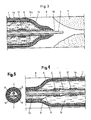
- Fig. 3 ein Längsschnitt durch das distale Ende eines dilatierten Ballons in einem schematisch dargestellten stenosierten Gefässabschnitt,
- Fig. 4 ein Längsschnitt durch den hinteren Bereich eines Dilatationsballons, und
- Fig. 5 ein Querschnitt durch den Schaft eines erfindungsgemässen Katheters.
- 1 schematically shows a stenosed vessel section with an inserted dilatation balloon,
- 2 shows a cross section through a dilatation balloon,
- 3 shows a longitudinal section through the distal end of a dilated balloon in a schematically illustrated stenosed vessel section,
- Fig. 4 is a longitudinal section through the rear region of a dilatation balloon, and
- 5 shows a cross section through the shaft of a catheter according to the invention.
Die Fig. 1 zeigt rein schematisch ein Blutgefäss 8 mit einer Stenose 7 und einen in das Gefäss perkutan eingesetzten Katheter mit einem Dilatationsballon 1 und einem Katheterschaft 2. Der Katheter wird mit einem Führungsdraht 4 in das Gefäss 8 eingesetzt. Der Führungsdraht 4 erstreckt sich durch den Schaft 2 und den Dilatationsballon 1 und kann an einer distalen Oeffnung 18 austreten. Wie die Fig. 5 zeigt, ist der Schaft 2 durch eine Wand 10 in ein Lumen 11 für den Führungsdraht 4 und ein Lumen 12 für Druckflüssigkeit unterteilt. Das Lumen 12 ist gemäss Fig. 4 über eine Oeffnung 9 mit dem Balloninnern 13 und am proximalen Ende mit einer Saug- und Druckpumpe 16 verbunden. Ueber die Pumpe 16 kann der Druck im Innern 13 des Dilatationsballons 1 genau reguliert und damit der Durchmesser des Ballons reguliert werden. Bei der Einführung des Katheters ist der Dilatationsballon 1 in bekannter Weise gefaltet. Im entfalteten Zustand ist der Dilatationsballon 1 wie aus Fig. 1 ersichtlich zwischen den beiden sich verjüngenden Enden aussenseitig zylindrisch.1 shows, purely schematically, a
Die Wandung 5 des Dilatationsballons 1 besteht gemäss Fig. 2 aus einer inneren Schicht 5a und einer äusseren Schicht 5b. Die innere Schicht 5a besteht aus einem vergleichsweise weichen Kunststoff und die äussere Schicht 5b vorzugsweise aus Silikonkautschuk. Die Wandung 5 des Dilatationsballons 1 ist im Gegensatz zu den bekannten Dilatationsballonen elastisch in gewissen Grenzen dehnbar. Auf die innere Schicht 5a sind Lichtleiterfasern oder -bündel 6 aufgeklebt und von der äusseren Schicht 5b überdeckt. Diese Lichtleiter 6 sind gleichmässig über den Umfang der Wandung 5 verteilt und verlaufen parallel zur Längsrichtung des Katheters. Die Austrittsstellen 6a der Lichtleiter 6 liegen bei dilatiertem Ballon 1 auf einem Kreis und in einer Ebene, welche den Dilatationsballon etwa im Uebergang zwischen seinem zylindrischen Bereich 1a und seinem distalen Verjüngungsbereich 1b schneidet. Die Lichtleiter 6 erstecken sich auch über die ganze Länge des Schaftes 2 und sind über ein Anschlussstück 14 mit einem Lasergerät 15 gekoppelt. Das Gerät 15 ist vorzugsweise ein pulsierender Xenon-Chlorid Excimer-Laser. Das vom Lasergerät 15 erzeugte Licht gelangt über das Anschlussstück 14 und den Schaft 2 bis zu den Austrittsstellen 6a der Lichtleiter 6.According to FIG. 2, the
Die Lichtleiter 6 weisen einen Durchmesser von beispielsweise 0,1 mm auf und sind sehr flexibel. Der Dilatationsballon 1 kann somit auch mit den eingelegten Lichtleitern 6 gefaltet werden. Der radiale Abstand der Lichtleiter 6 von der Mittellinie des Dilatationsballons 1 wächst mit zunehmendem Druck der im Ballon vorhandenen Flüssigkeit. Entsprechend ist der Abstand der Austrittsstellen 6a von der Mittellinie des Dilatationsballons 1 eine Funktion des über die Pumpe 16 regulierbaren Druckes. Da die Wandung 5 elastisch dehnbar ist, ist es über die Druckregulierung möglich, die Austrittsstellen 6a in Kreisen unterschiedlicher Radien anzuordnen. Entsprechend treffen die an den Austrittsstellen 6a austretenden Laserstrahlen mehr oder weniger weit von der Gefässinnenseite entfernt auf die Stenose 7. Bei vergleichsweise kleinem Druck im Dilatationsballon ist somit ein entsprechend intensives Laserlichtbündel auf das Zentrum der Stenose gerichtet. Bei höherem Druck werden hingegen die eher äusseren Bereiche der Stenose 7 mit weniger dichtem Laserlicht abgetragen.The
Der Dilatationsballon 1 wird zur Abtragung der Stenose 7 mit Laserlicht wie in Fig. 3 gezeigt vor der Stenose 7 positioniert. Mit einem Markierstreifen 17 kann die Position des Dilatationskatheters 1 beobachtet werden. Neben der Abtragung der Stenose mit Laserlichtenergie ist mit dem erfindungsgemässen Katheter auch die Anwendung der üblichen Ballondilatation denkbar. Ohne Katheterwechsel kann somit vor oder nach einer Behandlung mit Laserlichtenergie eine Stenose 7 mit dem Dilatationsballon 1 gedehnt werden.The
Claims (8)
Applications Claiming Priority (2)
| Application Number | Priority Date | Filing Date | Title |
|---|---|---|---|
| CH690/90 | 1990-03-05 | ||
| CH69090 | 1990-03-05 |
Publications (3)
| Publication Number | Publication Date |
|---|---|
| EP0446178A2 true EP0446178A2 (en) | 1991-09-11 |
| EP0446178A3 EP0446178A3 (en) | 1992-02-05 |
| EP0446178B1 EP0446178B1 (en) | 1994-11-02 |
Family
ID=4192889
Family Applications (1)
| Application Number | Title | Priority Date | Filing Date |
|---|---|---|---|
| EP91810140A Expired - Lifetime EP0446178B1 (en) | 1990-03-05 | 1991-03-04 | Angioplasty light guide catheter for stenosis ablation by means of laser energy |
Country Status (9)
| Country | Link |
|---|---|
| US (1) | US5176674A (en) |
| EP (1) | EP0446178B1 (en) |
| JP (1) | JPH0744955B2 (en) |
| AT (1) | ATE113460T1 (en) |
| AU (1) | AU633404B2 (en) |
| CA (1) | CA2037404C (en) |
| DE (2) | DE9016985U1 (en) |
| DK (1) | DK0446178T3 (en) |
| ES (1) | ES2062736T3 (en) |
Cited By (2)
| Publication number | Priority date | Publication date | Assignee | Title |
|---|---|---|---|---|
| WO1994024962A1 (en) * | 1993-04-28 | 1994-11-10 | Focal, Inc. | Apparatus and methods for intraluminal photothermoforming |
| EP0732085A1 (en) * | 1995-03-15 | 1996-09-18 | Cordis Europa N.V. | Balloon catheter with light-conductive basic body |
Families Citing this family (80)
| Publication number | Priority date | Publication date | Assignee | Title |
|---|---|---|---|---|
| US5222949A (en) * | 1991-07-23 | 1993-06-29 | Intermed, Inc. | Flexible, noncollapsible catheter tube with hard and soft regions |
| US5417653A (en) * | 1993-01-21 | 1995-05-23 | Sahota; Harvinder | Method for minimizing restenosis |
| US5423806A (en) * | 1993-10-01 | 1995-06-13 | Medtronic, Inc. | Laser extractor for an implanted object |
| US5484433A (en) * | 1993-12-30 | 1996-01-16 | The Spectranetics Corporation | Tissue ablating device having a deflectable ablation area and method of using same |
| US5466234A (en) * | 1994-01-31 | 1995-11-14 | Trimedyne, Inc. | Expandable laser catheter |
| US5395361A (en) * | 1994-06-16 | 1995-03-07 | Pillco Limited Partnership | Expandable fiberoptic catheter and method of intraluminal laser transmission |
| US5569197A (en) * | 1994-12-21 | 1996-10-29 | Schneider (Usa) Inc | Drug delivery guidewire |
| US6048349A (en) * | 1997-07-09 | 2000-04-11 | Intraluminal Therapeutics, Inc. | Systems and methods for guiding a medical instrument through a body |
| US5902299A (en) * | 1997-07-29 | 1999-05-11 | Jayaraman; Swaminathan | Cryotherapy method for reducing tissue injury after balloon angioplasty or stent implantation |
| DE19817553A1 (en) | 1998-04-15 | 1999-10-21 | Biotronik Mess & Therapieg | Ablation arrangement |
| JP2005534409A (en) * | 2002-08-05 | 2005-11-17 | ミラヴァント メディカル テクノロジーズ,インコーポレーテッド | Light transmission catheter |
| WO2004012805A2 (en) | 2002-08-05 | 2004-02-12 | Miravant Medical Technologies | Light delivery catheter |
| US8545488B2 (en) | 2004-09-17 | 2013-10-01 | The Spectranetics Corporation | Cardiovascular imaging system |
| US8628519B2 (en) * | 2004-09-17 | 2014-01-14 | The Spectranetics Corporation | Rapid exchange bias laser catheter design |
| US9867530B2 (en) | 2006-08-14 | 2018-01-16 | Volcano Corporation | Telescopic side port catheter device with imaging system and method for accessing side branch occlusions |
| US9596993B2 (en) | 2007-07-12 | 2017-03-21 | Volcano Corporation | Automatic calibration systems and methods of use |
| WO2009009802A1 (en) | 2007-07-12 | 2009-01-15 | Volcano Corporation | Oct-ivus catheter for concurrent luminal imaging |
| US9622706B2 (en) | 2007-07-12 | 2017-04-18 | Volcano Corporation | Catheter for in vivo imaging |
| US11141063B2 (en) | 2010-12-23 | 2021-10-12 | Philips Image Guided Therapy Corporation | Integrated system architectures and methods of use |
| US11040140B2 (en) | 2010-12-31 | 2021-06-22 | Philips Image Guided Therapy Corporation | Deep vein thrombosis therapeutic methods |
| WO2013033592A1 (en) | 2011-08-31 | 2013-03-07 | Volcano Corporation | Optical-electrical rotary joint and methods of use |
| EP2765944B1 (en) | 2011-10-14 | 2018-09-05 | RA Medical Systems | Small flexible liquid core catheter for laser ablation in body lumens |
| US9286673B2 (en) | 2012-10-05 | 2016-03-15 | Volcano Corporation | Systems for correcting distortions in a medical image and methods of use thereof |
| US9307926B2 (en) | 2012-10-05 | 2016-04-12 | Volcano Corporation | Automatic stent detection |
| US11272845B2 (en) | 2012-10-05 | 2022-03-15 | Philips Image Guided Therapy Corporation | System and method for instant and automatic border detection |
| US9367965B2 (en) | 2012-10-05 | 2016-06-14 | Volcano Corporation | Systems and methods for generating images of tissue |
| US9858668B2 (en) | 2012-10-05 | 2018-01-02 | Volcano Corporation | Guidewire artifact removal in images |
| US10070827B2 (en) | 2012-10-05 | 2018-09-11 | Volcano Corporation | Automatic image playback |
| US9324141B2 (en) | 2012-10-05 | 2016-04-26 | Volcano Corporation | Removal of A-scan streaking artifact |
| US10568586B2 (en) | 2012-10-05 | 2020-02-25 | Volcano Corporation | Systems for indicating parameters in an imaging data set and methods of use |
| EP2904671B1 (en) | 2012-10-05 | 2022-05-04 | David Welford | Systems and methods for amplifying light |
| US9292918B2 (en) | 2012-10-05 | 2016-03-22 | Volcano Corporation | Methods and systems for transforming luminal images |
| US9840734B2 (en) | 2012-10-22 | 2017-12-12 | Raindance Technologies, Inc. | Methods for analyzing DNA |
| EP2931132B1 (en) | 2012-12-13 | 2023-07-05 | Philips Image Guided Therapy Corporation | System for targeted cannulation |
| CA2895989A1 (en) | 2012-12-20 | 2014-07-10 | Nathaniel J. Kemp | Optical coherence tomography system that is reconfigurable between different imaging modes |
| US10942022B2 (en) | 2012-12-20 | 2021-03-09 | Philips Image Guided Therapy Corporation | Manual calibration of imaging system |
| US9730613B2 (en) | 2012-12-20 | 2017-08-15 | Volcano Corporation | Locating intravascular images |
| US10939826B2 (en) | 2012-12-20 | 2021-03-09 | Philips Image Guided Therapy Corporation | Aspirating and removing biological material |
| US11406498B2 (en) | 2012-12-20 | 2022-08-09 | Philips Image Guided Therapy Corporation | Implant delivery system and implants |
| CA2895502A1 (en) | 2012-12-20 | 2014-06-26 | Jeremy Stigall | Smooth transition catheters |
| EP2934653B1 (en) | 2012-12-21 | 2018-09-19 | Douglas Meyer | Rotational ultrasound imaging catheter with extended catheter body telescope |
| WO2014100530A1 (en) | 2012-12-21 | 2014-06-26 | Whiseant Chester | System and method for catheter steering and operation |
| JP2016508233A (en) | 2012-12-21 | 2016-03-17 | ナサニエル ジェイ. ケンプ, | Power efficient optical buffering using optical switches |
| US10058284B2 (en) | 2012-12-21 | 2018-08-28 | Volcano Corporation | Simultaneous imaging, monitoring, and therapy |
| US9486143B2 (en) | 2012-12-21 | 2016-11-08 | Volcano Corporation | Intravascular forward imaging device |
| US10166003B2 (en) | 2012-12-21 | 2019-01-01 | Volcano Corporation | Ultrasound imaging with variable line density |
| CA2895993A1 (en) | 2012-12-21 | 2014-06-26 | Jason Spencer | System and method for graphical processing of medical data |
| US9612105B2 (en) | 2012-12-21 | 2017-04-04 | Volcano Corporation | Polarization sensitive optical coherence tomography system |
| JP2016501623A (en) | 2012-12-21 | 2016-01-21 | アンドリュー ハンコック, | System and method for multipath processing of image signals |
| CA2896006A1 (en) | 2012-12-21 | 2014-06-26 | David Welford | Systems and methods for narrowing a wavelength emission of light |
| US10226597B2 (en) | 2013-03-07 | 2019-03-12 | Volcano Corporation | Guidewire with centering mechanism |
| EP2965263B1 (en) | 2013-03-07 | 2022-07-20 | Bernhard Sturm | Multimodal segmentation in intravascular images |
| US11154313B2 (en) | 2013-03-12 | 2021-10-26 | The Volcano Corporation | Vibrating guidewire torquer and methods of use |
| EP2967391A4 (en) | 2013-03-12 | 2016-11-02 | Donna Collins | Systems and methods for diagnosing coronary microvascular disease |
| US9320530B2 (en) | 2013-03-13 | 2016-04-26 | The Spectranetics Corporation | Assisted cutting balloon |
| US11026591B2 (en) | 2013-03-13 | 2021-06-08 | Philips Image Guided Therapy Corporation | Intravascular pressure sensor calibration |
| US9623211B2 (en) | 2013-03-13 | 2017-04-18 | The Spectranetics Corporation | Catheter movement control |
| US9301687B2 (en) | 2013-03-13 | 2016-04-05 | Volcano Corporation | System and method for OCT depth calibration |
| US10201387B2 (en) | 2013-03-13 | 2019-02-12 | The Spectranetics Corporation | Laser-induced fluid filled balloon catheter |
| JP6339170B2 (en) | 2013-03-13 | 2018-06-06 | ジンヒョン パーク | System and method for generating images from a rotating intravascular ultrasound device |
| US10842567B2 (en) | 2013-03-13 | 2020-11-24 | The Spectranetics Corporation | Laser-induced fluid filled balloon catheter |
| US9757200B2 (en) | 2013-03-14 | 2017-09-12 | The Spectranetics Corporation | Intelligent catheter |
| US10292677B2 (en) | 2013-03-14 | 2019-05-21 | Volcano Corporation | Endoluminal filter having enhanced echogenic properties |
| US11642169B2 (en) | 2013-03-14 | 2023-05-09 | The Spectranetics Corporation | Smart multiplexed medical laser system |
| US10219887B2 (en) | 2013-03-14 | 2019-03-05 | Volcano Corporation | Filters with echogenic characteristics |
| EP2967606B1 (en) | 2013-03-14 | 2018-05-16 | Volcano Corporation | Filters with echogenic characteristics |
| US9962527B2 (en) | 2013-10-16 | 2018-05-08 | Ra Medical Systems, Inc. | Methods and devices for treatment of stenosis of arteriovenous fistula shunts |
| EP3071125B1 (en) | 2013-11-18 | 2021-08-04 | Koninklijke Philips N.V. | Devices for thrombus dispersal |
| JP6517832B2 (en) | 2013-11-18 | 2019-05-22 | コーニンクレッカ フィリップス エヌ ヴェKoninklijke Philips N.V. | Guided thrombus dispersion catheter |
| US10987168B2 (en) | 2014-05-29 | 2021-04-27 | Spectranetics Llc | System and method for coordinated laser delivery and imaging |
| US11246659B2 (en) | 2014-08-25 | 2022-02-15 | The Spectranetics Corporation | Liquid laser-induced pressure wave emitting catheter sheath |
| US11058492B2 (en) | 2014-12-30 | 2021-07-13 | The Spectranetics Corporation | Laser-induced pressure wave emitting catheter sheath |
| US10646275B2 (en) | 2014-12-30 | 2020-05-12 | Regents Of The University Of Minnesota | Laser catheter with use of determined material type in vascular system in ablation of material |
| WO2016109736A1 (en) | 2014-12-30 | 2016-07-07 | The Spectranetics Corporation | Laser-induced fluid filled balloon catheter |
| US10646274B2 (en) | 2014-12-30 | 2020-05-12 | Regents Of The University Of Minnesota | Laser catheter with use of reflected light and force indication to determine material type in vascular system |
| WO2016109739A1 (en) | 2014-12-30 | 2016-07-07 | The Spectranetics Corporation | Electrically-induced pressure wave emitting catheter sheath |
| US10646118B2 (en) | 2014-12-30 | 2020-05-12 | Regents Of The University Of Minnesota | Laser catheter with use of reflected light to determine material type in vascular system |
| US10555772B2 (en) | 2015-11-23 | 2020-02-11 | Ra Medical Systems, Inc. | Laser ablation catheters having expanded distal tip windows for efficient tissue ablation |
| JP2019166289A (en) | 2018-03-22 | 2019-10-03 | ラ メディカル システムズ, インコーポレイテッド | Liquid filled ablation catheter with overjacket |
| US11517713B2 (en) * | 2019-06-26 | 2022-12-06 | Boston Scientific Scimed, Inc. | Light guide protection structures for plasma system to disrupt vascular lesions |
Citations (4)
| Publication number | Priority date | Publication date | Assignee | Title |
|---|---|---|---|---|
| US3498286A (en) * | 1966-09-21 | 1970-03-03 | American Optical Corp | Catheters |
| WO1987001273A1 (en) * | 1985-09-05 | 1987-03-12 | Fox Kenneth R | Method of and apparatus for laser treatment of body lumens |
| US4793359A (en) * | 1987-04-24 | 1988-12-27 | Gv Medical, Inc. | Centering balloon structure for transluminal angioplasty catheter |
| EP0311458A2 (en) * | 1987-10-08 | 1989-04-12 | The Beth Israel Hospital Association | Laser balloon catheter |
Family Cites Families (7)
| Publication number | Priority date | Publication date | Assignee | Title |
|---|---|---|---|---|
| IT1088048B (en) * | 1977-11-29 | 1985-06-04 | Magnasco Dante | RETRACTOR FOR MEDICAL FIELD APPLICATIONS |
| US5041108A (en) * | 1981-12-11 | 1991-08-20 | Pillco Limited Partnership | Method for laser treatment of body lumens |
| US5041089A (en) * | 1987-12-11 | 1991-08-20 | Devices For Vascular Intervention, Inc. | Vascular dilation catheter construction |
| US4966596A (en) * | 1988-08-08 | 1990-10-30 | The Beth Israel Hospital Association | Laser atherectomy catheter |
| EP0355200A1 (en) * | 1988-08-12 | 1990-02-28 | Advanced Cardiovascular Systems, Inc. | Balloon dilatation catheter with laser cutting capability |
| EP0387753A1 (en) * | 1989-03-17 | 1990-09-19 | Schott Glaswerke | Method and apparatus to protect the proximal coupling side of laser catheters |
| US4993412A (en) * | 1989-08-02 | 1991-02-19 | Eclipse Surgical Technologies, Inc. | Method and apparatus for removal of obstructive substance from body channels |
-
1990
- 1990-12-17 DE DE9016985U patent/DE9016985U1/de not_active Expired - Lifetime
-
1991
- 1991-02-15 US US07/656,933 patent/US5176674A/en not_active Expired - Lifetime
- 1991-03-01 CA CA002037404A patent/CA2037404C/en not_active Expired - Fee Related
- 1991-03-04 DK DK91810140.3T patent/DK0446178T3/en not_active Application Discontinuation
- 1991-03-04 DE DE59103382T patent/DE59103382D1/en not_active Expired - Fee Related
- 1991-03-04 AT AT91810140T patent/ATE113460T1/en not_active IP Right Cessation
- 1991-03-04 ES ES91810140T patent/ES2062736T3/en not_active Expired - Lifetime
- 1991-03-04 EP EP91810140A patent/EP0446178B1/en not_active Expired - Lifetime
- 1991-03-04 AU AU72084/91A patent/AU633404B2/en not_active Ceased
- 1991-03-05 JP JP3038743A patent/JPH0744955B2/en not_active Expired - Lifetime
Patent Citations (4)
| Publication number | Priority date | Publication date | Assignee | Title |
|---|---|---|---|---|
| US3498286A (en) * | 1966-09-21 | 1970-03-03 | American Optical Corp | Catheters |
| WO1987001273A1 (en) * | 1985-09-05 | 1987-03-12 | Fox Kenneth R | Method of and apparatus for laser treatment of body lumens |
| US4793359A (en) * | 1987-04-24 | 1988-12-27 | Gv Medical, Inc. | Centering balloon structure for transluminal angioplasty catheter |
| EP0311458A2 (en) * | 1987-10-08 | 1989-04-12 | The Beth Israel Hospital Association | Laser balloon catheter |
Cited By (2)
| Publication number | Priority date | Publication date | Assignee | Title |
|---|---|---|---|---|
| WO1994024962A1 (en) * | 1993-04-28 | 1994-11-10 | Focal, Inc. | Apparatus and methods for intraluminal photothermoforming |
| EP0732085A1 (en) * | 1995-03-15 | 1996-09-18 | Cordis Europa N.V. | Balloon catheter with light-conductive basic body |
Also Published As
| Publication number | Publication date |
|---|---|
| DE9016985U1 (en) | 1991-03-07 |
| ATE113460T1 (en) | 1994-11-15 |
| ES2062736T3 (en) | 1994-12-16 |
| EP0446178B1 (en) | 1994-11-02 |
| JPH0744955B2 (en) | 1995-05-17 |
| EP0446178A3 (en) | 1992-02-05 |
| AU7208491A (en) | 1991-09-05 |
| US5176674A (en) | 1993-01-05 |
| AU633404B2 (en) | 1993-01-28 |
| JPH04341277A (en) | 1992-11-27 |
| CA2037404C (en) | 1998-03-31 |
| DK0446178T3 (en) | 1995-02-27 |
| DE59103382D1 (en) | 1994-12-08 |
| CA2037404A1 (en) | 1991-09-06 |
Similar Documents
| Publication | Publication Date | Title |
|---|---|---|
| EP0446178B1 (en) | Angioplasty light guide catheter for stenosis ablation by means of laser energy | |
| DE60307897T2 (en) | ROTATING CUTTING AND DILATATION BALLOON | |
| DE2848484C2 (en) | endoscope | |
| DE60225147T2 (en) | BALLOON CATHETER AND METHOD FOR STABILIZING THE STRENGTH | |
| DE60204258T2 (en) | Feather for folding a catheter balloon | |
| EP0479730B1 (en) | Balloon dilatation catheter | |
| DE60305494T2 (en) | BALLOON CATHETER | |
| DE3690224C2 (en) | Vascular plastic coronary balloon probe | |
| DE60021173T2 (en) | BIFURKATIONSSTENTEINFÜHRSYSTEM | |
| DE69635967T2 (en) | Rapid exchange stent delivery balloon catheter | |
| DE69839157T2 (en) | FULLURENE KATHERDERSYSTEM CONTAINING | |
| DE69830227T2 (en) | BALLOON CATHETER FOR THE REPAIR OF REFILLING BLOOD VESSELS | |
| DE69825411T2 (en) | Balloon catheter with extended flexible distal extremity | |
| DE69828623T2 (en) | CATHETER WITH SAFETY DISTANCE STRUCTURE | |
| EP0605764A1 (en) | Device for implantation and extraction of stents | |
| DE3337258A1 (en) | DILATATION CATHETER | |
| EP0630617A1 (en) | Suction catheter assembly | |
| EP0218885A2 (en) | Dilatation catheter | |
| DE60319652T2 (en) | balloon catheter | |
| DE3402573A1 (en) | Balloon dilation apparatus with a cutting tool on a primarily single-lumen multi-purpose catheter | |
| DE69636833T2 (en) | CATHETER FOR THE LEFT CORONATERY | |
| DE10025266B4 (en) | Catheter arrangement with improved guiding device | |
| EP0393343A1 (en) | Uretero-renoscope | |
| EP0904799A1 (en) | Dilation catheter with balloon having a determined ration of balloon volume and square surface of the inflation lumen | |
| DE69418905T3 (en) | SELECTIVE ARRANGEMENT OF SLIDING COATINGS ON BALLOON CATHETERS |
Legal Events
| Date | Code | Title | Description |
|---|---|---|---|
| PUAI | Public reference made under article 153(3) epc to a published international application that has entered the european phase |
Free format text: ORIGINAL CODE: 0009012 |
|
| AK | Designated contracting states |
Kind code of ref document: A2 Designated state(s): AT BE CH DE DK ES FR GB GR IT LI LU NL SE |
|
| PUAL | Search report despatched |
Free format text: ORIGINAL CODE: 0009013 |
|
| AK | Designated contracting states |
Kind code of ref document: A3 Designated state(s): AT BE CH DE DK ES FR GB GR IT LI LU NL SE |
|
| 17P | Request for examination filed |
Effective date: 19920304 |
|
| RAP1 | Party data changed (applicant data changed or rights of an application transferred) |
Owner name: SCHNEIDER (EUROPE) AG |
|
| 17Q | First examination report despatched |
Effective date: 19940318 |
|
| GRAA | (expected) grant |
Free format text: ORIGINAL CODE: 0009210 |
|
| AK | Designated contracting states |
Kind code of ref document: B1 Designated state(s): AT BE CH DE DK ES FR GB GR IT LI LU NL SE |
|
| PG25 | Lapsed in a contracting state [announced via postgrant information from national office to epo] |
Ref country code: GR Free format text: LAPSE BECAUSE OF FAILURE TO SUBMIT A TRANSLATION OF THE DESCRIPTION OR TO PAY THE FEE WITHIN THE PRESCRIBED TIME-LIMIT Effective date: 19941102 |
|
| REF | Corresponds to: |
Ref document number: 113460 Country of ref document: AT Date of ref document: 19941115 Kind code of ref document: T |
|
| ITF | It: translation for a ep patent filed |
Owner name: BUGNION S.P.A. |
|
| REF | Corresponds to: |
Ref document number: 59103382 Country of ref document: DE Date of ref document: 19941208 |
|
| REG | Reference to a national code |
Ref country code: ES Ref legal event code: FG2A Ref document number: 2062736 Country of ref document: ES Kind code of ref document: T3 |
|
| ET | Fr: translation filed | ||
| EAL | Se: european patent in force in sweden |
Ref document number: 91810140.3 |
|
| REG | Reference to a national code |
Ref country code: DK Ref legal event code: T3 |
|
| GBT | Gb: translation of ep patent filed (gb section 77(6)(a)/1977) |
Effective date: 19950126 |
|
| PG25 | Lapsed in a contracting state [announced via postgrant information from national office to epo] |
Ref country code: LU Free format text: LAPSE BECAUSE OF NON-PAYMENT OF DUE FEES Effective date: 19950331 |
|
| PLBI | Opposition filed |
Free format text: ORIGINAL CODE: 0009260 |
|
| 26 | Opposition filed |
Opponent name: BIOTRONIK MESS- UND THERAPIEGERAETE GMBH & CO INGE Effective date: 19950802 |
|
| NLR1 | Nl: opposition has been filed with the epo |
Opponent name: BIOTRONIK MESS- UND THERAPIEGERAETE GMBH & CO INGE |
|
| PLBF | Reply of patent proprietor to notice(s) of opposition |
Free format text: ORIGINAL CODE: EPIDOS OBSO |
|
| PLBF | Reply of patent proprietor to notice(s) of opposition |
Free format text: ORIGINAL CODE: EPIDOS OBSO |
|
| PLBL | Opposition procedure terminated |
Free format text: ORIGINAL CODE: EPIDOS OPPC |
|
| PLBM | Termination of opposition procedure: date of legal effect published |
Free format text: ORIGINAL CODE: 0009276 |
|
| PLAC | Information related to filing of opposition modified |
Free format text: ORIGINAL CODE: 0008299OPPO |
|
| 27C | Opposition proceedings terminated |
Effective date: 19980415 |
|
| NLR2 | Nl: decision of opposition | ||
| PGFP | Annual fee paid to national office [announced via postgrant information from national office to epo] |
Ref country code: DK Payment date: 19990209 Year of fee payment: 9 |
|
| PGFP | Annual fee paid to national office [announced via postgrant information from national office to epo] |
Ref country code: AT Payment date: 19990210 Year of fee payment: 9 |
|
| PGFP | Annual fee paid to national office [announced via postgrant information from national office to epo] |
Ref country code: SE Payment date: 19990216 Year of fee payment: 9 |
|
| PGFP | Annual fee paid to national office [announced via postgrant information from national office to epo] |
Ref country code: CH Payment date: 19990218 Year of fee payment: 9 |
|
| PGFP | Annual fee paid to national office [announced via postgrant information from national office to epo] |
Ref country code: BE Payment date: 19990302 Year of fee payment: 9 |
|
| PGFP | Annual fee paid to national office [announced via postgrant information from national office to epo] |
Ref country code: ES Payment date: 19990311 Year of fee payment: 9 |
|
| PLAD | Information related to termination of opposition procedure modified |
Free format text: ORIGINAL CODE: 0009299OPPC |
|
| STAA | Information on the status of an ep patent application or granted ep patent |
Free format text: STATUS: OPPOSITION PROCEDURE CLOSED |
|
| R27C | Opposition proceedings terminated (corrected) |
Effective date: 19980510 |
|
| NLXE | Nl: other communications concerning ep-patents (part 3 heading xe) |
Free format text: PAT. BUL. 12/98: CORR.: 10.05.1998 |
|
| PG25 | Lapsed in a contracting state [announced via postgrant information from national office to epo] |
Ref country code: DK Free format text: LAPSE BECAUSE OF NON-PAYMENT OF DUE FEES Effective date: 20000304 Ref country code: AT Free format text: LAPSE BECAUSE OF NON-PAYMENT OF DUE FEES Effective date: 20000304 |
|
| PG25 | Lapsed in a contracting state [announced via postgrant information from national office to epo] |
Ref country code: SE Free format text: LAPSE BECAUSE OF NON-PAYMENT OF DUE FEES Effective date: 20000305 |
|
| PG25 | Lapsed in a contracting state [announced via postgrant information from national office to epo] |
Ref country code: ES Free format text: LAPSE BECAUSE OF NON-PAYMENT OF DUE FEES Effective date: 20000306 |
|
| PG25 | Lapsed in a contracting state [announced via postgrant information from national office to epo] |
Ref country code: LI Free format text: LAPSE BECAUSE OF NON-PAYMENT OF DUE FEES Effective date: 20000331 Ref country code: CH Free format text: LAPSE BECAUSE OF NON-PAYMENT OF DUE FEES Effective date: 20000331 Ref country code: BE Free format text: LAPSE BECAUSE OF NON-PAYMENT OF DUE FEES Effective date: 20000331 |
|
| BERE | Be: lapsed |
Owner name: SCHNEIDER (EUROPE) A.G. Effective date: 20000331 |
|
| EUG | Se: european patent has lapsed |
Ref document number: 91810140.3 |
|
| REG | Reference to a national code |
Ref country code: CH Ref legal event code: PL |
|
| REG | Reference to a national code |
Ref country code: DK Ref legal event code: EBP |
|
| PGFP | Annual fee paid to national office [announced via postgrant information from national office to epo] |
Ref country code: NL Payment date: 20001222 Year of fee payment: 11 |
|
| PGFP | Annual fee paid to national office [announced via postgrant information from national office to epo] |
Ref country code: GB Payment date: 20010202 Year of fee payment: 11 |
|
| PGFP | Annual fee paid to national office [announced via postgrant information from national office to epo] |
Ref country code: FR Payment date: 20010301 Year of fee payment: 11 |
|
| PGFP | Annual fee paid to national office [announced via postgrant information from national office to epo] |
Ref country code: DE Payment date: 20010330 Year of fee payment: 11 |
|
| REG | Reference to a national code |
Ref country code: ES Ref legal event code: FD2A Effective date: 20011010 |
|
| REG | Reference to a national code |
Ref country code: GB Ref legal event code: IF02 |
|
| PG25 | Lapsed in a contracting state [announced via postgrant information from national office to epo] |
Ref country code: GB Free format text: LAPSE BECAUSE OF NON-PAYMENT OF DUE FEES Effective date: 20020304 |
|
| PG25 | Lapsed in a contracting state [announced via postgrant information from national office to epo] |
Ref country code: NL Free format text: LAPSE BECAUSE OF NON-PAYMENT OF DUE FEES Effective date: 20021001 Ref country code: DE Free format text: LAPSE BECAUSE OF NON-PAYMENT OF DUE FEES Effective date: 20021001 |
|
| GBPC | Gb: european patent ceased through non-payment of renewal fee |
Effective date: 20020304 |
|
| PG25 | Lapsed in a contracting state [announced via postgrant information from national office to epo] |
Ref country code: FR Free format text: LAPSE BECAUSE OF NON-PAYMENT OF DUE FEES Effective date: 20021129 |
|
| NLV4 | Nl: lapsed or anulled due to non-payment of the annual fee |
Effective date: 20021001 |
|
| REG | Reference to a national code |
Ref country code: FR Ref legal event code: ST |
|
| PG25 | Lapsed in a contracting state [announced via postgrant information from national office to epo] |
Ref country code: IT Free format text: LAPSE BECAUSE OF NON-PAYMENT OF DUE FEES;WARNING: LAPSES OF ITALIAN PATENTS WITH EFFECTIVE DATE BEFORE 2007 MAY HAVE OCCURRED AT ANY TIME BEFORE 2007. THE CORRECT EFFECTIVE DATE MAY BE DIFFERENT FROM THE ONE RECORDED. Effective date: 20050304 |