EP0446610A1 - Magnified phased array with a digital beamforming network - Google Patents
Magnified phased array with a digital beamforming network Download PDFInfo
- Publication number
- EP0446610A1 EP0446610A1 EP91101693A EP91101693A EP0446610A1 EP 0446610 A1 EP0446610 A1 EP 0446610A1 EP 91101693 A EP91101693 A EP 91101693A EP 91101693 A EP91101693 A EP 91101693A EP 0446610 A1 EP0446610 A1 EP 0446610A1
- Authority
- EP
- European Patent Office
- Prior art keywords
- array
- signals
- digital
- antenna system
- magnified
- Prior art date
- Legal status (The legal status is an assumption and is not a legal conclusion. Google has not performed a legal analysis and makes no representation as to the accuracy of the status listed.)
- Withdrawn
Links
Images

Classifications
-
- H—ELECTRICITY
- H01—ELECTRIC ELEMENTS
- H01Q—ANTENNAS, i.e. RADIO AERIALS
- H01Q25/00—Antennas or antenna systems providing at least two radiating patterns
- H01Q25/007—Antennas or antenna systems providing at least two radiating patterns using two or more primary active elements in the focal region of a focusing device
- H01Q25/008—Antennas or antenna systems providing at least two radiating patterns using two or more primary active elements in the focal region of a focusing device lens fed multibeam arrays
-
- H—ELECTRICITY
- H01—ELECTRIC ELEMENTS
- H01Q—ANTENNAS, i.e. RADIO AERIALS
- H01Q3/00—Arrangements for changing or varying the orientation or the shape of the directional pattern of the waves radiated from an antenna or antenna system
- H01Q3/26—Arrangements for changing or varying the orientation or the shape of the directional pattern of the waves radiated from an antenna or antenna system varying the relative phase or relative amplitude of energisation between two or more active radiating elements; varying the distribution of energy across a radiating aperture
- H01Q3/2658—Phased-array fed focussing structure
Definitions
- the present invention relates generally to phased array antenna systems and more particularly to a magnified phased array antenna system which incorporates a digital beamforming network therein.
- phased array antenna systems typically incorporate a large number of antenna elements.
- the large number of antenna elements is generally required to provide sufficient gain.
- such large conventional phased array antenna systems are generally reconfigurable.
- the beams profiles employed in such conventional antennas are easily maneuverable, and are not susceptible to jamming due to their generally agile nature.
- the beamforming process generally involves the use of phase shifters are required to provide time delays among the different antenna elements. Consequently, the beamforming process does not involve simple coefficient multiplication of the signal vectors to achieve signal detection and steering.
- the present invention provides for a magnified phased array antenna system that incorporates a digital beamforming network therein.
- the number of antenna elements is therefore reduced compared to conventional antennas.
- the incorporation of the digital beamforming network permits the formation of multiple simultaneous beams that are reconfigurable and which may be steered in a variety of selectable directions.
- the field of view of the present invention is therefore limited, but the gain of the system is enhanced by the use of the magnifying portion thereof.
- This magnifying portion may be a telescope, such as a Cassegrain telescope, or the like, and may include a transfer lens that is employed to provide an intermediate focal plane on which the outputs of the antenna elements are imaged.
- the magnified phased array has a focal plane located at the plane radiating surface of the transfer lens, which is used to radiate the transmitted signals to remote locations or focus incoming signals for processing by the feed array system.
- the present invention provides apparatus which achieves adequate gain using a minimum number of antenna elements.
- the digital beamforming network provides multibeam capability in an effective manner.
- the network provides for fast scanning spot beams and reconfigurable area coverage beams.
- the present invention has a reduced number of elements, thus reducing manufacturing costs.
- Compared to a conventional multibeam antenna its reliability is improved because of redundancy in the array.
- the use of digital beamforming provides for multiple, simultaneous, reconfigurable beams.
- the optimal efficiency of the present invention is achieved by dynamically allocating the spatial (beam forming) and temporal (waveform detection) processing sequence.
- the present invention provides for a magnified phased array antenna system comprising an array of antenna elements and a magnification section having a predetermined field of view coupled to the array of antenna elements which increases the gain of the antenna system.
- a converter section coupled to the array of antenna elements which converts analog output signals derived from each of the elements in the array into digital signals when the antenna system operates in receive mode, and converts digital signals into analog signals transmittable by each of the elements in the array when the antenna system operates in transmit mode.
- a digital beamforming network is coupled to the converter section which processes each of the digital signals derived from the elements of the array when the antenna system operates in receive mode by multiplying each of the digital signals by separate directional vectors and combining each of the multiplied digital signals into a single digital signal whose signal components are in phase, which digital signal represents a beam formed in the direction of the signals received by the array.
- the digital beamforming network also processes a digital signal to generate a beam transmittable in a predetermined direction when the antenna system operates in transmit mode by multiplying it by separate directional vectors having predetermined phase relationships such that the phase vectors associated with each of the digital signals generated thereby are such that upon transmission by the array, a beam is formed in the predetermined direction.
- Multiple simultaneous beams are selectively formed in a plurality of directions by multiplying the transmitted signal by a plurality of separate sets of beam coefficients.
- a beam magnification section is optically coupled to the array of antenna elements which magnifies the respective beams provided by the digital beamforming network.
- the digital beamforming network comprises circuitry that provides a plurality of directional vectors corresponding to directions from which or toward which the multiple simultaneous beam are received or transmitted, respectively.
- a plurality of multipliers are employed to combine a plurality of directional vectors with corresponding signals provided by the array of antenna elements.
- the multipliers provide a respective plurality of output signals which are substantially in phase.
- a summing circuit is coupled to the plurality of multipliers which combines the plurality of output signals into a single digital output string for each beam direction.
- each beam requires a set of phase shifters in order to achieve such agility.
- the conventional array has a large field of view, a large number of elements, for multiple beams, multiple sets of phase shifters are required, and the system has reasonable gain.
- the magnified phased array of the present invention has a limited field of view, moderate number of elements employs a digital beam former with no phase shifters, is capable of forming multiple beams, and has higher gain than the conventional phased array.
- the system 10 comprises a magnification system 12 which in FIG. 1 is shown as a Cassegrain antenna comprising a transfer lens 14, a first reflector 16 and a second reflector 18.
- magnification systems may also be employed including confocal lens systems or a confocal reflector system, or a single reflector with a transfer lens, such as is known by those skilled in the art.
- An antenna array 20 comprising a plurality of antenna elements is arranged in a conventional manner on the focal plane of the transfer lens 14.
- an array of as few as sixteen (16) antenna elements may he employed.
- Each of the antenna element in the array 20 is coupled to a digital beamforming network (DBN) 22.
- DBN digital beamforming network
- FIG. 2 illustrates the digital beamforming network 22 of the system 10 of FIG. 1 when operating in receive mode. Shown in FIG. 2 is the array 20 of antenna elements, represented by elements 20a-20n. Each of the antenna elements 20a-20n is coupled to down conversion circuitry 26 employed to convert signals received by the antenna array 20 into intermediate frequency (IF) signals which may be processed by the digital beamforming network 22.
- IF intermediate frequency
- the down conversion circuitry 26 may be comprised of a local oscillator generator 30a which includes a local oscillator 32a, coupled by way of a buffer amplifier 34a to a frequency multiplexer 36a (identified as X8).
- the output of the oscillator generator 30a is coupled to one input of a mixer 40a whose other input is coupled to the the first antenna element 20a.
- the output of the mixer 40a is connected to a band pass filter (BPF) 42a and a buffer amplifier 44 to an analog to digital conversion section 50.
- BPF band pass filter
- Each of the antenna elements 20a-20n of the array 20 is individually coupled by way of separate down conversion circuitry 26 to the analog to digital conversion section 50.
- the analog to digital conversion section 50 is comprised of a plurality of analog to digital converters 50a-50n which separately convert the output signals from the down converter sections 26a-26n into digital signals which may be processed by the digital beamforming network 22.
- the analog to digital converters 50a-50n are coupled by way of decimate/presum circuits 52a-52n which may comprise digital circuitry such as accumulator, sign detector. This presuming operation usually will increase the dynamic range and reduce the processing bandwidth.
- Outputs of the decimate/presum circuits 52a-52n are coupled to respective inputs of the digital beamforming network 22.
- the digital beamforming network 22 comprises a plurality of digital multipliers 60a-60n which each have one input provided by the outputs of respective decimate/presum circuits 52a-52n and have the other input coupled to beam coefficient generation circuitry 62a-62n which computes beam directional vectors.
- Outputs of each of the digital multipliers 60a-60n are coupled to a summing circuit 64 which combines the digital output signals into a single digital signal.
- the output of the summing circuit 64 is the output of the digital beamforming network 22, which may be processed, as an example of communications receiver, by means of a temporal processing circuitry 66 that performs demodulation, channelization decoding, data storage and forwarding.
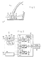
- FIG. 3 it illustrates the digital beamforming network 22 of the system 10 of FIG. 1 when operating in transmit mode.
- the circuitry of FIG. 3 is substantially the same as the circuitry shown in FIG. 2, except that the converter section 50 uses a plurality of digital to analog converters 50a'-50n', no decimate/presum circuits 52a-52n are employed the summing circuit 64 is replaced by a 1:N multiplexer 70, and input signals to be transmitted by the system 10 in transmit mode are provided by a base band data circuit 72 coupled to the multiplexer 70, which may be a data bus.
- the digital beamforming network 22 is comprised of the plurality of digital multipliers 60a-60n whose inputs are coupled to receive the output signals of the plurality of antenna elements 20a-20n and beam coefficients from the beam coefficient generation circuitry 62.
- the outputs of the plurality of digital multipliers 60a-60n are coupled to the summing circuit 70.
- Beam coefficients may be provided by means of the central processor, for example.
- each of the signals received by the antenna elements 20a-20n is separately combined with beam coefficients which are adapted to multiply the respective signals in order to generate signals which are in phase with one another.
- These signals are combined into a single signal by means of the summing circuit 70 which provides a signal representative of a formed beam whose beam direction vector points toward the radiating source.
- a four by four array 20 of antenna elements may be employed having an operational frequency centered at 60 GHz.
- a transmitted signal received by the antenna array 20 is amplified, down converted and dehopped to the processing intermediate frequency (IF) by means of the down conversion circuitry 26.
- the dehopped IF analog signals are then converted to digital signals after down conversion by the converter circuit 50, which in this case is comprised of the plurality of analog to digital converters 50a-50n.
- the down conversion will convert the 60 GHz signal with a 2 GHz hopping bandwidth and a 50 MHz instantaneous bandwidth, for example, to about a 1 GHz signal with 50 MHz bandwidth.
- the decimate/presum circuits 52a-52n may be employed to reduce the bandwidth requirements and enhance dynamic range of the digital signals processed by the digital beamforming network 22.
- the incoming signals arrives at the antenna array 20 such that the phase vectors of the signal received by adjacent antenna elements 20a-20n are rotated progressively, as is shown more clearly in FIG. 4.
- the spatial rotational rate in degrees per element spacing depends on the angle of arrival.
- a signal provided by a mechanical boresight, or other reference signal source is processed, the rotational rate thereof is zero.
- Every antenna element 20a-20n is sampled separately and each signal may be represented as a signal vector.
- the digitized signal vectors are then multiplied by beam coefficients (directional vectors) in the digital beamforming network 22 such that the products are all in phase. These in phase signals are then added together by means of the summing circuit 64 to provide the single digital output signal.
- the digital beamforming process digitally aligns the signals received by each of the antenna elements 20a-20n. Therefore, a beam is formed toward the incoming signal direction.
- multiple beams may be formed simultaneously by independently multiplying the signal vector by different directional vectors. In this manner, multiple received beams can be simultaneously processed, multiple transmit beams can be simultaneously processed, or the transmitted beam can be quickly steered to any desired direction by appropriately selecting the beam direction coefficients.
- the magnified phased array antenna system 10 may be implemented in numerous ways, including employing Cassegrain reflectors 12 and a transfer lens 14 arrangement.
- the transfer lens is disposed at the focal plane of the Cassegrain reflector system 12.
- the antenna array 20 In operation in the transmit mode, the antenna array 20 focuses radiated power at a small spot on the rear surface of the transfer lens 14. This spot serves as a virtual source to illuminate the Cassegrain reflector 12, which generates a spot beam in the far field. As the antenna array 20 focuses its radiated power at a different spot on the transfer lens 14, the beam in the far field will by "moved” accordingly. If two spots are created on the transfer lens 14, there will be two simultaneous spot beams in the far field. As more and more spot beams are generated, they are summed together to form an area coverage beam with instantaneous reconfigurability.
- the present invention provides apparatus which achieves adequate gain using a minimum number of antenna elements.
- the digital beamforming network provides multibeam capability in an effective manner.
- the network provides for fast scanning spot beams and reconfigurable area coverage beams.
- the present invention has a reduced number of elements, thus reducing manufacturing costs.
- Compared to a conventional multibeam antenna its reliability is improved because of redundancy in the array.
- the use of digital beamforming provides for multiple, simultaneous, reconfigurable beams.
- the optimal efficiency of the present invention is achieved by dynamically allocating the spatial (beam forming) and temporal (waveform detection) processing sequence.
Abstract
A magnified phased array antenna system (10) incorporating a digital beamforming network (22) therein. The magnified phased array antenna system (10) comprises a reflector system (12) employing a transfer lens (14) disposed at the focal plane of the reflector system (12) and an antenna array (20) which illuminates or receives energy from the transfer lens (14). In satellite to/from ground links where the field of view is limited, the present invention achieves adequate gain using a minimum number of antenna elements. The digital beamforming network (22) provides multibeam capability in an effective manner. The digital beamforming network (22) provides for fast scanning spot beams and reconfigurable area coverage beams. The present invention has a reduced number of elements, and its reliability is improved because of redundancy in the array. The use of digital beamforming provides for multiple, simultaneous, reconfigurable beams.
Description
- The present invention relates generally to phased array antenna systems and more particularly to a magnified phased array antenna system which incorporates a digital beamforming network therein.
- Conventional phased array antenna systems typically incorporate a large number of antenna elements. The large number of antenna elements is generally required to provide sufficient gain. In addition, such large conventional phased array antenna systems are generally reconfigurable. As such the beams profiles employed in such conventional antennas are easily maneuverable, and are not susceptible to jamming due to their generally agile nature. Furthermore, in large aperture array antennas in which large scan volumes are require, the beamforming process generally involves the use of phase shifters are required to provide time delays among the different antenna elements. Consequently, the beamforming process does not involve simple coefficient multiplication of the signal vectors to achieve signal detection and steering.
- In order to overcome the limitations of conventional phased array antenna systems, including their large number of elements and multiple sets of phase shifters and complex feeds, the present invention provides for a magnified phased array antenna system that incorporates a digital beamforming network therein. The number of antenna elements is therefore reduced compared to conventional antennas. The incorporation of the digital beamforming network permits the formation of multiple simultaneous beams that are reconfigurable and which may be steered in a variety of selectable directions. The field of view of the present invention is therefore limited, but the gain of the system is enhanced by the use of the magnifying portion thereof. This magnifying portion may be a telescope, such as a Cassegrain telescope, or the like, and may include a transfer lens that is employed to provide an intermediate focal plane on which the outputs of the antenna elements are imaged. The magnified phased array has a focal plane located at the plane radiating surface of the transfer lens, which is used to radiate the transmitted signals to remote locations or focus incoming signals for processing by the feed array system.
- In geo-synchronous satellite to/from ground links where the field of view is limited, the present invention provides apparatus which achieves adequate gain using a minimum number of antenna elements. The digital beamforming network provides multibeam capability in an effective manner. The network provides for fast scanning spot beams and reconfigurable area coverage beams.
- Therefore comparing the present invention to a conventional phased array antenna system, it has a reduced number of elements, thus reducing manufacturing costs. Compared to a conventional multibeam antenna, its reliability is improved because of redundancy in the array. Compared to a conventional antenna array, the use of digital beamforming provides for multiple, simultaneous, reconfigurable beams. In addition, the optimal efficiency of the present invention is achieved by dynamically allocating the spatial (beam forming) and temporal (waveform detection) processing sequence.
- In particular, the present invention provides for a magnified phased array antenna system comprising an array of antenna elements and a magnification section having a predetermined field of view coupled to the array of antenna elements which increases the gain of the antenna system. A converter section coupled to the array of antenna elements which converts analog output signals derived from each of the elements in the array into digital signals when the antenna system operates in receive mode, and converts digital signals into analog signals transmittable by each of the elements in the array when the antenna system operates in transmit mode.
- A digital beamforming network is coupled to the converter section which processes each of the digital signals derived from the elements of the array when the antenna system operates in receive mode by multiplying each of the digital signals by separate directional vectors and combining each of the multiplied digital signals into a single digital signal whose signal components are in phase, which digital signal represents a beam formed in the direction of the signals received by the array. The digital beamforming network also processes a digital signal to generate a beam transmittable in a predetermined direction when the antenna system operates in transmit mode by multiplying it by separate directional vectors having predetermined phase relationships such that the phase vectors associated with each of the digital signals generated thereby are such that upon transmission by the array, a beam is formed in the predetermined direction.
- Multiple simultaneous beams are selectively formed in a plurality of directions by multiplying the transmitted signal by a plurality of separate sets of beam coefficients. A beam magnification section is optically coupled to the array of antenna elements which magnifies the respective beams provided by the digital beamforming network.
- The digital beamforming network comprises circuitry that provides a plurality of directional vectors corresponding to directions from which or toward which the multiple simultaneous beam are received or transmitted, respectively. A plurality of multipliers are employed to combine a plurality of directional vectors with corresponding signals provided by the array of antenna elements. The multipliers provide a respective plurality of output signals which are substantially in phase. A summing circuit is coupled to the plurality of multipliers which combines the plurality of output signals into a single digital output string for each beam direction.
- To compare the present invention to a conventional array, although the conventional array can be very agile, each beam requires a set of phase shifters in order to achieve such agility. More particularly, the conventional array has a large field of view, a large number of elements, for multiple beams, multiple sets of phase shifters are required, and the system has reasonable gain. The magnified phased array of the present invention has a limited field of view, moderate number of elements employs a digital beam former with no phase shifters, is capable of forming multiple beams, and has higher gain than the conventional phased array.
- The various features and advantages of the present invention may be more readily understood with reference to the following detailed description taken in conjunction with the accompanying drawings, wherein like reference numerals designate like structural elements, and in which:
- FIG. 1 illustrates a magnified phased array antenna system in accordance with the principles of the present invention;
- FIG. 2 illustrates the digital beamforming network of the system of FIG. 1 when operating in receive mode;
- FIG. 3 illustrates the digital beamforming network of the system of FIG. 1 when operating in transmit mode; and
- FIG. 4 illustrates a detailed diagram illustrating the operation of the digital beamforming network of the present invention.
- Referring to FIG. 1, a magnified phased
array antenna system 10 in accordance with the principles of the present invention is shown. Thesystem 10 comprises amagnification system 12 which in FIG. 1 is shown as a Cassegrain antenna comprising atransfer lens 14, afirst reflector 16 and asecond reflector 18. Other magnification systems may also be employed including confocal lens systems or a confocal reflector system, or a single reflector with a transfer lens, such as is known by those skilled in the art. Anantenna array 20 comprising a plurality of antenna elements is arranged in a conventional manner on the focal plane of thetransfer lens 14. In the magnified phasedarray antenna system 10 of the present invention, an array of as few as sixteen (16) antenna elements may he employed. Each of the antenna element in thearray 20 is coupled to a digital beamforming network (DBN) 22. - FIG. 2 illustrates the
digital beamforming network 22 of thesystem 10 of FIG. 1 when operating in receive mode. Shown in FIG. 2 is thearray 20 of antenna elements, represented byelements 20a-20n. Each of theantenna elements 20a-20n is coupled to downconversion circuitry 26 employed to convert signals received by theantenna array 20 into intermediate frequency (IF) signals which may be processed by thedigital beamforming network 22. - The
down conversion circuitry 26 may be comprised of a local oscillator generator 30a which includes a local oscillator 32a, coupled by way of a buffer amplifier 34a to a frequency multiplexer 36a (identified as X8). The output of the oscillator generator 30a is coupled to one input of a mixer 40a whose other input is coupled to the thefirst antenna element 20a. The output of the mixer 40a is connected to a band pass filter (BPF) 42a and a buffer amplifier 44 to an analog todigital conversion section 50. - Each of the
antenna elements 20a-20n of thearray 20 is individually coupled by way of separate downconversion circuitry 26 to the analog todigital conversion section 50. The analog todigital conversion section 50 is comprised of a plurality of analog todigital converters 50a-50n which separately convert the output signals from thedown converter sections 26a-26n into digital signals which may be processed by thedigital beamforming network 22. - As shown in FIG. 2, the analog to
digital converters 50a-50n are coupled by way of decimate/presum circuits 52a-52n which may comprise digital circuitry such as accumulator, sign detector. This presuming operation usually will increase the dynamic range and reduce the processing bandwidth. - Outputs of the decimate/
presum circuits 52a-52n are coupled to respective inputs of thedigital beamforming network 22. Thedigital beamforming network 22 comprises a plurality ofdigital multipliers 60a-60n which each have one input provided by the outputs of respective decimate/presum circuits 52a-52n and have the other input coupled to beam coefficient generation circuitry 62a-62n which computes beam directional vectors. Outputs of each of thedigital multipliers 60a-60n are coupled to a summing circuit 64 which combines the digital output signals into a single digital signal. The output of the summing circuit 64 is the output of thedigital beamforming network 22, which may be processed, as an example of communications receiver, by means of atemporal processing circuitry 66 that performs demodulation, channelization decoding, data storage and forwarding. - With reference to FIG. 3, it illustrates the
digital beamforming network 22 of thesystem 10 of FIG. 1 when operating in transmit mode. The circuitry of FIG. 3 is substantially the same as the circuitry shown in FIG. 2, except that theconverter section 50 uses a plurality of digital toanalog converters 50a'-50n', no decimate/presum circuits 52a-52n are employed the summing circuit 64 is replaced by a 1:N multiplexer 70, and input signals to be transmitted by thesystem 10 in transmit mode are provided by a base band data circuit 72 coupled to themultiplexer 70, which may be a data bus. - With reference to FIG. 4, a diagram illustrating the operation of the
digital beamforming network 22 utilized in the circuits of FIGS. 2 and 3 are shown. Thedigital beamforming network 22 is comprised of the plurality ofdigital multipliers 60a-60n whose inputs are coupled to receive the output signals of the plurality ofantenna elements 20a-20n and beam coefficients from the beamcoefficient generation circuitry 62. The outputs of the plurality ofdigital multipliers 60a-60n are coupled to the summingcircuit 70. Beam coefficients may be provided by means of the central processor, for example. - As is shown in FIG. 4 and represented by the plurality of
arrows 78 having varying degrees of angular rotation which are representative of the relative amount of phase difference in the signals received by the plurality ofantenna elements 20a-20n derived from a single signal source viewed by theantenna array 20. Each of the signals received by theantenna elements 20a-20n is separately combined with beam coefficients which are adapted to multiply the respective signals in order to generate signals which are in phase with one another. These signals are combined into a single signal by means of the summingcircuit 70 which provides a signal representative of a formed beam whose beam direction vector points toward the radiating source. - With reference to FIG. 1, the operation of the magnified phased
array antenna system 10 operating in receive mode will be described. For example, a four by fourarray 20 of antenna elements may be employed having an operational frequency centered at 60 GHz. A transmitted signal received by theantenna array 20 is amplified, down converted and dehopped to the processing intermediate frequency (IF) by means of thedown conversion circuitry 26. The dehopped IF analog signals are then converted to digital signals after down conversion by theconverter circuit 50, which in this case is comprised of the plurality of analog todigital converters 50a-50n. Typically, the down conversion will convert the 60 GHz signal with a 2 GHz hopping bandwidth and a 50 MHz instantaneous bandwidth, for example, to about a 1 GHz signal with 50 MHz bandwidth. The decimate/presum circuits 52a-52n may be employed to reduce the bandwidth requirements and enhance dynamic range of the digital signals processed by thedigital beamforming network 22. - The incoming signals arrives at the
antenna array 20 such that the phase vectors of the signal received byadjacent antenna elements 20a-20n are rotated progressively, as is shown more clearly in FIG. 4. The spatial rotational rate in degrees per element spacing depends on the angle of arrival. When a signal provided by a mechanical boresight, or other reference signal source, is processed, the rotational rate thereof is zero. The further the angle of arrival of a particular signal is from boresight, the faster the rotational rate thereof. Everyantenna element 20a-20n is sampled separately and each signal may be represented as a signal vector. The digitized signal vectors are then multiplied by beam coefficients (directional vectors) in thedigital beamforming network 22 such that the products are all in phase. These in phase signals are then added together by means of the summing circuit 64 to provide the single digital output signal. - Consequently, the digital beamforming process digitally aligns the signals received by each of the
antenna elements 20a-20n. Therefore, a beam is formed toward the incoming signal direction. In a similar manner, multiple beams may be formed simultaneously by independently multiplying the signal vector by different directional vectors. In this manner, multiple received beams can be simultaneously processed, multiple transmit beams can be simultaneously processed, or the transmitted beam can be quickly steered to any desired direction by appropriately selecting the beam direction coefficients. - With reference to FIGS. 1 and 2, the magnified phased
array antenna system 10 may be implemented in numerous ways, including employingCassegrain reflectors 12 and atransfer lens 14 arrangement. The transfer lens is disposed at the focal plane of theCassegrain reflector system 12. - In operation in the transmit mode, the
antenna array 20 focuses radiated power at a small spot on the rear surface of thetransfer lens 14. This spot serves as a virtual source to illuminate theCassegrain reflector 12, which generates a spot beam in the far field. As theantenna array 20 focuses its radiated power at a different spot on thetransfer lens 14, the beam in the far field will by "moved" accordingly. If two spots are created on thetransfer lens 14, there will be two simultaneous spot beams in the far field. As more and more spot beams are generated, they are summed together to form an area coverage beam with instantaneous reconfigurability. - In satellite to/from ground links where the field of view is limited, the present invention provides apparatus which achieves adequate gain using a minimum number of antenna elements. The digital beamforming network provides multibeam capability in an effective manner. The network provides for fast scanning spot beams and reconfigurable area coverage beams.
- Therefore comparing the present invention to a conventional phased array antenna system, it has a reduced number of elements, thus reducing manufacturing costs. Compared to a conventional multibeam antenna, its reliability is improved because of redundancy in the array. Compared to a conventional antenna array, the use of digital beamforming provides for multiple, simultaneous, reconfigurable beams. In addition, the optimal efficiency of the present invention is achieved by dynamically allocating the spatial (beam forming) and temporal (waveform detection) processing sequence.
- Thus there has been described a new and improved phased array antenna system. It is to be understood that the above-described embodiments are merely illustrative of some of the many specific embodiments which represent applications of the principles of the present invention. Clearly, numerous and other arrangements can be readily devised by those skilled in the art without departing from the scope of the invention.
Claims (7)
- A magnified phased array antenna system comprising:
an array of antenna elements;
magnification means having a predetermined field of view coupled to the array of antenna elements for increasing the gain of the antenna system;
conversion means coupled to the array of antenna elements for (a) converting analog output signals derived from each of the elements in the array into digital signals when the antenna system operates in receive mode, and for (b) converting digital signals into analog signals transmittable by each of the elements in the array when the antenna system operates in transmit mode; and
digital beamforming means coupled to the conversion means for (a) processing each of the digital signals derived from the elements of the array when the antenna system operates in receive mode by multiplying each of the digital signals by separate directional vectors and combining each of the multiplied digital signals into a single digital signal whose signal components are in phase, which digital signal represents a beam formed in the direction of the signals received by the array, and for (b) processing a digital signal to generate a beam transmittable in a predetermined direction when the antenna system operates in transmit mode by multiplying it by separate directional vectors having predetermined phase relationships such that the phase vectors associated with each of the digital signals generated thereby are such that upon transmission by the array, a beam is formed in the predetermined direction. - The magnified phased array antenna system of Claim 1 wherein said digital beamforming means comprises:
coefficient generation means for providing a plurality of directional vectors corresponding to directions from which a signal is received by the array, or toward which a beam is to be transmitted, respectively;
a plurality of multiplying means for combining the plurality of directional vectors with corresponding ones of the signals provided by the array of antenna elements or corresponding signals which are to be transmitted by the system; and
summing means coupled to the plurality of multiplying means for combining the plurality of output signals into a single output signal when the antenna system operates in receive mode and for multiplexing the digital signal which is to be transmitted into a plurality of individual signals which are summed with the plurality of directional vectors in the multiplying means. - The magnified phased array antenna system of Claim 1 wherein said magnification means comprises:
reflector means for transmitting and receiving the beams and for focusing the beams in the far field; and
a transfer lens disposed between the array of antenna elements and the reflector means for coupling the beams therebetween. - The magnified phased array antenna system of Claim 3 wherein said reflector means comprises:
Cassegrain reflector and transfer lens means for magnifying the respective beams provided by the digital beamforming means. - The magnified phased array antenna system of Claim 1 which further comprises:
computer means coupled to the digital beamforming means for providing beam direction coefficients which determine the directions from which or toward which the beams are received or transmitted, respectively. - The magnified phased array antenna system of Claim 1 which further comprises:
down conversion means coupled between the array of antenna elements and the conversion means for reducing the data rate at which signals are processed by the system. - The magnified phased array antenna system of Claim 6 wherein said down conversion means further comprises:
separate down conversion and presuming means coupled to each antenna element of the array of antenna elements for individually reducing the data rate and enhancing the dynamic range at which signals are processed by the digital beamforming means.
Applications Claiming Priority (2)
| Application Number | Priority Date | Filing Date | Title |
|---|---|---|---|
| US49002890A | 1990-03-07 | 1990-03-07 | |
| US490028 | 1990-03-07 |
Publications (1)
| Publication Number | Publication Date |
|---|---|
| EP0446610A1 true EP0446610A1 (en) | 1991-09-18 |
Family
ID=23946316
Family Applications (1)
| Application Number | Title | Priority Date | Filing Date |
|---|---|---|---|
| EP91101693A Withdrawn EP0446610A1 (en) | 1990-03-07 | 1991-02-07 | Magnified phased array with a digital beamforming network |
Country Status (2)
| Country | Link |
|---|---|
| EP (1) | EP0446610A1 (en) |
| JP (1) | JPH04220003A (en) |
Cited By (8)
| Publication number | Priority date | Publication date | Assignee | Title |
|---|---|---|---|---|
| EP0483686A1 (en) * | 1990-10-31 | 1992-05-06 | Rockwell International Corporation | Multiple beam antenna system |
| FR2685551A1 (en) * | 1991-12-23 | 1993-06-25 | Alcatel Espace | ACTIVE ANTENNA "OFFSET" WITH DOUBLE REFLECTORS. |
| WO1997021284A1 (en) * | 1995-12-07 | 1997-06-12 | Ericsson, Inc. | Efficient apparatus for simultaneous modulation and digital beamforming for an antenna array |
| US5929808A (en) * | 1997-10-14 | 1999-07-27 | Teledesic Llc | System and method for the acquisition of a non-geosynchronous satellite signal |
| EP1050926A2 (en) * | 1999-05-04 | 2000-11-08 | Hughes Electronics Corporation | Hybridized space/ground beam forming |
| EP0929825B1 (en) * | 1996-10-07 | 2003-04-02 | Rowe-Deines Instruments, Incorporated | Two-dimensional array transducer and beamformer |
| DE102008057088B4 (en) * | 2008-11-13 | 2014-07-10 | Deutsches Zentrum für Luft- und Raumfahrt e.V. | Reflector antenna, in particular for receiving and / or transmitting signals from and / or to satellites |
| GB2546309A (en) * | 2016-01-15 | 2017-07-19 | Cambridge Broadband Networks Ltd | An Antenna |
Citations (4)
| Publication number | Priority date | Publication date | Assignee | Title |
|---|---|---|---|---|
| EP0109322A1 (en) * | 1982-11-05 | 1984-05-23 | Thomson-Csf | Double reflector antenna for a tracking radar improving the target acquisition capability |
| GB2130798A (en) * | 1982-10-06 | 1984-06-06 | Standard Telephones Cables Ltd | Digital beam-forming radar |
| FR2588422A1 (en) * | 1985-10-08 | 1987-04-10 | Thomson Csf | Electronic scanning antenna having a small number of radiating and phase-shifting elements, and a restricted scanning angle |
| EP0276817A2 (en) * | 1987-01-27 | 1988-08-03 | Mitsubishi Denki Kabushiki Kaisha | Conformal array antenna |
-
1991
- 1991-02-07 EP EP91101693A patent/EP0446610A1/en not_active Withdrawn
- 1991-03-07 JP JP3067889A patent/JPH04220003A/en active Pending
Patent Citations (4)
| Publication number | Priority date | Publication date | Assignee | Title |
|---|---|---|---|---|
| GB2130798A (en) * | 1982-10-06 | 1984-06-06 | Standard Telephones Cables Ltd | Digital beam-forming radar |
| EP0109322A1 (en) * | 1982-11-05 | 1984-05-23 | Thomson-Csf | Double reflector antenna for a tracking radar improving the target acquisition capability |
| FR2588422A1 (en) * | 1985-10-08 | 1987-04-10 | Thomson Csf | Electronic scanning antenna having a small number of radiating and phase-shifting elements, and a restricted scanning angle |
| EP0276817A2 (en) * | 1987-01-27 | 1988-08-03 | Mitsubishi Denki Kabushiki Kaisha | Conformal array antenna |
Cited By (19)
| Publication number | Priority date | Publication date | Assignee | Title |
|---|---|---|---|---|
| EP0483686A1 (en) * | 1990-10-31 | 1992-05-06 | Rockwell International Corporation | Multiple beam antenna system |
| FR2685551A1 (en) * | 1991-12-23 | 1993-06-25 | Alcatel Espace | ACTIVE ANTENNA "OFFSET" WITH DOUBLE REFLECTORS. |
| EP0548876A1 (en) * | 1991-12-23 | 1993-06-30 | Alcatel Espace | An active offset antenna having two reflectors |
| US5321413A (en) * | 1991-12-23 | 1994-06-14 | Alcatel Espace | Offset active antenna having two reflectors |
| AU663137B2 (en) * | 1991-12-23 | 1995-09-28 | Alcatel N.V. | Dual reflector offset active antenna |
| AU720057B2 (en) * | 1995-12-07 | 2000-05-25 | Ericsson Inc. | Efficient apparatus for simultaneous modulation and digital beamforming for an antenna array |
| WO1997021284A1 (en) * | 1995-12-07 | 1997-06-12 | Ericsson, Inc. | Efficient apparatus for simultaneous modulation and digital beamforming for an antenna array |
| US5909460A (en) * | 1995-12-07 | 1999-06-01 | Ericsson, Inc. | Efficient apparatus for simultaneous modulation and digital beamforming for an antenna array |
| US6219375B1 (en) | 1995-12-07 | 2001-04-17 | Ericsson Inc. | Apparatus for performing multiplication of a vector of multi-bit values by a matrix of multi-bit coefficients |
| US6404821B1 (en) | 1995-12-07 | 2002-06-11 | Ericsson Inc. | Digital beamformer for receiving a first number of information signals using a second number of antenna array elements |
| CN1124706C (en) * | 1995-12-07 | 2003-10-15 | 艾利森公司 | Efficient apparatus for simultaneous modulation and digital beamforming for an antenna array |
| EP0929825B1 (en) * | 1996-10-07 | 2003-04-02 | Rowe-Deines Instruments, Incorporated | Two-dimensional array transducer and beamformer |
| US5929808A (en) * | 1997-10-14 | 1999-07-27 | Teledesic Llc | System and method for the acquisition of a non-geosynchronous satellite signal |
| EP1050926A2 (en) * | 1999-05-04 | 2000-11-08 | Hughes Electronics Corporation | Hybridized space/ground beam forming |
| US6571081B1 (en) | 1999-05-04 | 2003-05-27 | Hughes Electronics Corporation | Hybridized space/ground beam forming |
| EP1050926A3 (en) * | 1999-05-04 | 2002-07-31 | Hughes Electronics Corporation | Hybridized space/ground beam forming |
| DE102008057088B4 (en) * | 2008-11-13 | 2014-07-10 | Deutsches Zentrum für Luft- und Raumfahrt e.V. | Reflector antenna, in particular for receiving and / or transmitting signals from and / or to satellites |
| GB2546309A (en) * | 2016-01-15 | 2017-07-19 | Cambridge Broadband Networks Ltd | An Antenna |
| GB2546309B (en) * | 2016-01-15 | 2020-03-18 | Cambridge Broadband Networks Ltd | An Antenna |
Also Published As
| Publication number | Publication date |
|---|---|
| JPH04220003A (en) | 1992-08-11 |
Similar Documents
| Publication | Publication Date | Title |
|---|---|---|
| EP0963006B1 (en) | Reconfigurable multiple beam satellite phased array antenna | |
| US9287961B2 (en) | Receive only smart ground-terminal antenna for geostationary satellites in slightly inclined orbits | |
| EP0276817B1 (en) | Conformal array antenna | |
| EP1122813B1 (en) | An improved phased array terminal for equatorial satellite constellations | |
| US6018316A (en) | Multiple beam antenna system and method | |
| US5130718A (en) | Multiple dichroic surface cassegrain reflector | |
| AU613458B2 (en) | An electronically scanned antenna | |
| US5038147A (en) | Electronically scanned antenna | |
| EP0618641A2 (en) | Ultra wideband phased array antenna | |
| US4972151A (en) | Steered-beam satellite communication system | |
| RU96122171A (en) | ANTENNA SYSTEM | |
| EP0248886B1 (en) | High efficiency optical limited scan antenna | |
| US6043776A (en) | Mobile satellite communication system | |
| EP0446610A1 (en) | Magnified phased array with a digital beamforming network | |
| US6563473B2 (en) | Low sidelobe contiguous-parabolic reflector array | |
| US5321413A (en) | Offset active antenna having two reflectors | |
| KR20010072866A (en) | One-dimensional interleaved multi-beam antenna | |
| US6504516B1 (en) | Hexagonal array antenna for limited scan spatial applications | |
| CN111366918A (en) | Sidelobe cutting method and device | |
| US6404398B1 (en) | Indirect radiating array techniques | |
| EP0427201B1 (en) | Satellite beam-forming network system having improved beam shaping | |
| JPH073688Y2 (en) | Antenna device | |
| Kiuchi et al. | Tactical cylindrical active phased array radar | |
| JP2000068730A (en) | Antenna device | |
| Bunton et al. | SKA cost model for wide field-of-view options |
Legal Events
| Date | Code | Title | Description |
|---|---|---|---|
| PUAI | Public reference made under article 153(3) epc to a published international application that has entered the european phase |
Free format text: ORIGINAL CODE: 0009012 |
|
| AK | Designated contracting states |
Kind code of ref document: A1 Designated state(s): DE FR GB IT |
|
| STAA | Information on the status of an ep patent application or granted ep patent |
Free format text: STATUS: THE APPLICATION IS DEEMED TO BE WITHDRAWN |
|
| 18D | Application deemed to be withdrawn |
Effective date: 19920319 |