EP0447745A2 - Device for the radioactive radiation treatment of a body cavity - Google Patents
Device for the radioactive radiation treatment of a body cavity Download PDFInfo
- Publication number
- EP0447745A2 EP0447745A2 EP91100310A EP91100310A EP0447745A2 EP 0447745 A2 EP0447745 A2 EP 0447745A2 EP 91100310 A EP91100310 A EP 91100310A EP 91100310 A EP91100310 A EP 91100310A EP 0447745 A2 EP0447745 A2 EP 0447745A2
- Authority
- EP
- European Patent Office
- Prior art keywords
- webs
- radiation source
- elastically deformable
- axially
- tube
- Prior art date
- Legal status (The legal status is an assumption and is not a legal conclusion. Google has not performed a legal analysis and makes no representation as to the accuracy of the status listed.)
- Withdrawn
Links
Images
Classifications
-
- A—HUMAN NECESSITIES
- A61—MEDICAL OR VETERINARY SCIENCE; HYGIENE
- A61N—ELECTROTHERAPY; MAGNETOTHERAPY; RADIATION THERAPY; ULTRASOUND THERAPY
- A61N5/00—Radiation therapy
- A61N5/10—X-ray therapy; Gamma-ray therapy; Particle-irradiation therapy
- A61N5/1001—X-ray therapy; Gamma-ray therapy; Particle-irradiation therapy using radiation sources introduced into or applied onto the body; brachytherapy
- A61N5/1014—Intracavitary radiation therapy
-
- A—HUMAN NECESSITIES
- A61—MEDICAL OR VETERINARY SCIENCE; HYGIENE
- A61N—ELECTROTHERAPY; MAGNETOTHERAPY; RADIATION THERAPY; ULTRASOUND THERAPY
- A61N5/00—Radiation therapy
- A61N5/10—X-ray therapy; Gamma-ray therapy; Particle-irradiation therapy
- A61N5/1001—X-ray therapy; Gamma-ray therapy; Particle-irradiation therapy using radiation sources introduced into or applied onto the body; brachytherapy
- A61N5/1007—Arrangements or means for the introduction of sources into the body
- A61N2005/1008—Apparatus for temporary insertion of sources, e.g. afterloaders
Definitions
- the invention relates to a device for treating the interior of the body with radioactive radiation with a radiation source which can be moved in an extension tube to the treatment site, in particular for endoluminal radiation of a central bronchial carcinoma.
- a single dose of 5 Gy occurs at a distance of 10 mm is calculated on the radiation source, in the middle of the irradiated distance single doses of 91 Gy on the applicator surface.
- the dose upon direct contact of the applicator with the mucous membrane or tumor surface is approximately 8 Gy.
- the bronchial wall is enclosed here by the 10 Gy isodose and is loaded with small volumes of 20 Gy and more.
- the opposite bronchial wall receives only doses between 5 and 7 Gy when the applicator is applied on one side, and there is only a single dose of 2.5 Gy at a tissue depth of 5 mm. A tumor therefore hardly receives effective doses at this point.
- the one-sided application of the applicator to the bronchial wall and the small applicator diameter therefore lead to an extremely uneven dose distribution with overdosing in the contact area and underdosing on the opposite bronchial wall.
- the invention is therefore based on the object of providing a device for treating the inside of the body which, with a small diameter of the applicator, results in a uniformly rotationally symmetrical dose distribution in the radiation area.
- This object is achieved according to the invention in a device of the type mentioned at the outset by at least one remote-controlled expansion head which is arranged in the region of the radiation source and keeps an axial passage clear.
- the device according to the invention can be inserted into the inside of the body without any problems thanks to its small diameter and allows a uniform, rotationally symmetrical dose distribution to be achieved at the site of the irradiation. It is important that the centering expansion head leaves a sufficiently large axial passage when the applicator is in the lumen of the main bronchus or trachea to avoid obstruction of the airways.
- the axial passage is preferably achieved in that the spreading and centering head has radially expandable webs, between which there are sufficiently large gaps during spreading.
- An axially guided pulling and / or pushing device is advantageously used to spread the webs, with which the webs of the expansion head are actuated.
- the radial expansion path can be adapted to the width of the bronchial system.
- the device according to the invention can be realized in a particularly simple manner with radially expandable webs if at least three slots are made uniformly at one or more points on the circumference of an elastically deformable hose. As a result, tubular jacket strips are formed between the slots, which correspond to the radially expandable webs.
- the elastically deformable hose surrounds the extension hose for the radiation source as an outer hose (coaxial system).
- jacket strips can be compressed by means of the pulling and / or pushing device in such a way that the jacket strips expand or bulge into webs between the slots.
- the required diameter of the expansion head can be achieved.
- the free ends of the extension hose and the elastically deformable hose are axially immovably connected to one another in the region of the radiation source and a device for axially displacing the elastically deformable hose relative to the extension hose is arranged in the region of the loading and / or storage station.
- the device for axially displacing the elastically deformable hose relative to the extension hose can be made up of a threaded rod at the outer end of the extension hose and supported on it and supported at the outer end of the elastically deformable hose Mother exist.
- This nut can be adjusted by hand, a scale graduation arranged on the threaded rod indicating the degree of radial protrusion of the webs set up.
- a controlled centering of the radiation source can be achieved in situ without impairing the ventilation.
- a tube is first placed endoscopically at the exit of the main bronchus.
- the applicator is brought to the desired position through the tube, after which the tube is withdrawn and the applicator remains in the lumen of the main bronchus.
- the positioning of the webs of the expanding head can be checked endoscopically.
- the central position in the bronchial air shadow can be demonstrated by means of a marking made in the X-ray image.
- a bronchial applicator with the centering and spreading head according to the invention is a largely open bronchial or tracheal lumen, which must be created by laser removal of larger stenosing tumor parts.
- Another advantage of the device according to the invention is that it can be connected to any commercially available loading and / or storage station or to any reloading device.
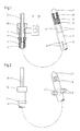
- An extension hose 1 which generally consists of polytetrafluoroethylene, serves as a guide for a radiation source 2 which can be displaced by means of a cable 3 in the extension hose 1.
- the extension hose 1 and the cable 3 can be coupled to a loading and / or storage station, not shown, which serves to store the radiation source 2 in a radiation-protected manner and to bring it in remotely through the extension tube 1 into the interior of the patient to be treated without the treatment personnel being endangered by the radioactive radiation.
- an elastically deformable tube 4 Arranged around the extension tube 1 is an elastically deformable tube 4, which has sufficient play against it has the extension tube 1 so that they can be axially displaced relative to each other.
- the extension hose 1 and the elastically deformable hose 4 are axially immovably connected to one another via a metallic end piece 7, for example by grooves 8 screwed into the end piece, in which the end of the elastically deformable hose 4 is clawed.
- slots 5 in the elastically deformable tube 4 which are axially parallel and distributed uniformly over the circumference. At least three slots 5, but preferably four and more, can be arranged on the circumference, as a result of which 5 tubular strips 6 are formed between the slots, which form the radially spread webs of the expansion head.
- the free end of the extension tube 1 has a threaded tube 9 onto which a nut 10 is screwed.
- This nut 10 is supported on a flange 11 at the end of the elastically deformable hose 4. If the nut 10 is now turned against the flange 11, the threaded tube 9 and the associated extension tube 1 are pulled out of the elastically deformable tube 4. As a result, the elastically deformable hose 4 is compressed, which causes the webs 6 to be set up in the region of the slots 5.
- the threaded tube 9 is provided with a scale 12, which can be calibrated directly to the diameter of the radially positioned webs 6.
- the nut 10 is coupled to a rotary drive 13, which can have a display device 14 for the extent of the radial expansion of the webs 6.
- the slots can have a length of 10 mm and are located at a distance of 10 and 30 mm from the end piece 7.
- the diameter of the expansion head is a maximum of 16 mm.
- two expansion heads with slot lengths of 10 mm are advantageously arranged at a distance of 15 to 20 mm from each other.
- An applicator with more than two spreading heads and a larger diameter is advantageous for tracheal radiation.
Abstract
Description
Die Erfindung betrifft eine Vorrichtung zum Behandeln des Körperinneren mit radioaktiver Strahlung mit in einem Ausfahrschlauch zum Behandlungsort verfahrbaren Strahlenquelle, insbesondere zum endoluminalen Bestrahlen eines zentralen Bronchialkarzinoms.The invention relates to a device for treating the interior of the body with radioactive radiation with a radiation source which can be moved in an extension tube to the treatment site, in particular for endoluminal radiation of a central bronchial carcinoma.
Eine derartige endoluminale Bestrahlung hat sich in der Palliativbehandlung zentraler Bronchialkarzinome als wirksam erwiesen und wird in Verbindung mit einer perkutanen Strahlenbehandlung als Methode der lokalen Dosiserhöhung ("Boost") zunehmend häufiger auch mit kurativer Zielsetzung angewendet. Bisherige Vorrichtungen zum endoluminalen Bestrahlen des Tracheal- und Bronchialbereiches besitzen den Nachteil, daß hohe örtliche Dosisbelastungen an der Tumoroberfläche oder der Bronchialschleimhaut auftreten können. Des weiteren darf die Ventilation der großen Stammbronchien bei den häufig ateminsuffizienten Patienten nicht durch eine zusätzliche künstliche Obstruktion beeinträchtigt werden. Es ist daher erforderlich, möglichst dünne Applikatorschläuche zü verwenden, die den Querschnitt der Stammbronchien nicht unnötig vermindern, jedoch liegt das Ende derartiger Applikatorschläuche mit der Strahlenquelle in der Regel einseitig an einer Wand des Hauptbronchus oder - bei Bestrahlung zentral sitzender Oberlappenkarzinome - an der Wand des Oberlappenbronchus an. Dies hängt mit der zum Einführen des Applikatorschlauchs und zum Einbringen der Strahlenquelle erforderlichen Mindeststeifheit zusammen.Such endoluminal radiation has been shown to be effective in the palliative treatment of central bronchial carcinomas and is being used increasingly in conjunction with percutaneous radiation treatment as a method of local dose increase (“boost”) with a curative objective. Previous devices for endoluminal irradiation of the tracheal and bronchial area have the disadvantage that high local dose loads can occur on the tumor surface or the bronchial mucosa. Furthermore, the ventilation of the large trunk bronchi in the frequently respiratory insufficiency patients must not be impaired by an additional artificial obstruction. It is therefore necessary to use applicator hoses which are as thin as possible and which do not unnecessarily reduce the cross-section of the trunk bronchi, but the end of such applicator hoses with the radiation source is generally one-sided on a wall of the main bronchus or Irradiation of centrally located upper lobe carcinomas - on the wall of the upper lobe bronchus. This is related to the minimum stiffness required to insert the applicator tube and the radiation source.
Liegt das Ende des Applikatorschlauchs mit der Strahlenquelle an einer Wand eines Bronchus an, so treten bei einem Applikator mit 4 mm Durchmesser und einer mit einer Strahlenquelle beladenen Strecke von 40 mm bei einer Einzeldosis von 5 Gy, die auf eine Entfernung von 10 mm in bezug auf die Strahlenquelle berechnet ist, in der Mitte der bestrahlten Strecke Einzeldosen von 91 Gy an der Applikatoroberfläche auf. In einer Gewebetiefe von 5 mm beträgt die Dosis bei unmittelbarem Kontakt des Applikators mit der Schleimhaut oder Tumoroberfläche ungefähr 8 Gy. Die Bronchialwand wird hier von der 10 Gy-Isodose umschlossen und kleinvolumig mit 20 Gy und mehr belastet. Die gegenüberliegende Bronchialwand erhält bei einseitiger Anlage des Applikators nur Dosen zwischen 5 und 7 Gy, und in 5 mm Gewebetiefe liegt nur eine Einzeldosis von 2,5 Gy vor. Ein Tumor erhält an dieser Stelle daher kaum noch wirksame Dosen. Das einseitige Anliegen des Applikators an der Bronchialwand sowie der geringe Applikatordurchmesser führen daher zu einer äußerst ungleichmäßigen Dosisverteilung mit Überdosierung im Kontaktbereich und Unterdosierungen an der gegenüberliegenden Bronchialwand.If the end of the applicator tube with the radiation source lies against a wall of a bronchus, then with an applicator with a diameter of 4 mm and a distance of 40 mm loaded with a radiation source, a single dose of 5 Gy occurs at a distance of 10 mm is calculated on the radiation source, in the middle of the irradiated distance single doses of 91 Gy on the applicator surface. At a tissue depth of 5 mm, the dose upon direct contact of the applicator with the mucous membrane or tumor surface is approximately 8 Gy. The bronchial wall is enclosed here by the 10 Gy isodose and is loaded with small volumes of 20 Gy and more. The opposite bronchial wall receives only doses between 5 and 7 Gy when the applicator is applied on one side, and there is only a single dose of 2.5 Gy at a tissue depth of 5 mm. A tumor therefore hardly receives effective doses at this point. The one-sided application of the applicator to the bronchial wall and the small applicator diameter therefore lead to an extremely uneven dose distribution with overdosing in the contact area and underdosing on the opposite bronchial wall.
Schon kleinvolumige Überdosierungen im vorgeschädigten Bronchialsystem, z.B nach Operationen, Laserungen oder perkutanen Strahlenbehandlungen können zu schweren Komplikationen führen. Endoluminale Bestrahlungen im Bereich des tracheobronchialen Systems, wo zumeist zirkulär wachsende Tumore auftreten, setzen eine auf die Bronchialwand bezogene gleichmäßig rotationssymmetrische Dosisverteilung voraus.Even small-volume overdoses in the previously damaged bronchial system, for example after operations, laser treatments or percutaneous radiation treatments, can lead to serious complications. Endoluminal radiation in the area of the tracheobronchial system, where mostly circularly growing tumors occur, require a uniformly rotationally symmetrical dose distribution based on the bronchial wall.
Der Erfindung liegt daher die Aufgabe zugrunde, eine Vorrichtung zum Behandeln des Körperinneren zu schaffen, die bei kleinem Durchmesser des Applikators eine gleichmäßig rotationssymmetrische Dosisverteilung im Bestrahlungsbereich ergibt.The invention is therefore based on the object of providing a device for treating the inside of the body which, with a small diameter of the applicator, results in a uniformly rotationally symmetrical dose distribution in the radiation area.
Gelöst wird diese Aufgabe bei einer Vorrichtung der eingangs erwähnten Art erfindungsgemäß durch mindestens einen ferngesteuerten, im Bereich der Strahlenquelle angeordneten, einen axialen Durchlaß freihaltenden Spreizkopf.This object is achieved according to the invention in a device of the type mentioned at the outset by at least one remote-controlled expansion head which is arranged in the region of the radiation source and keeps an axial passage clear.
Die erfindungsgemäße Vorrichtung läßt sich im ungespreizten Zustand dank ihres geringen Durchmessers problemlos ins Körperinnere einführen und erlaubt es, am Ort der Bestrahlung eine gleichmäßige rotationssymmetrische Dosisverteilung zu erreichen. Wichtig ist, daß der zentrierende Spreizkopf einen ausreichend großen axialen Durchlaß freiläßt, wenn sich der Applikator im Lumen des Hauptbronchus oder der Trachea befindet, um eine Obstruktion der Atemwege zu vermeiden.Thanks to its small diameter, the device according to the invention can be inserted into the inside of the body without any problems thanks to its small diameter and allows a uniform, rotationally symmetrical dose distribution to be achieved at the site of the irradiation. It is important that the centering expansion head leaves a sufficiently large axial passage when the applicator is in the lumen of the main bronchus or trachea to avoid obstruction of the airways.
Vorzugsweise wird der axiale Durchlaß dadurch erreicht, daß der Spreiz- und Zentrierkopf radial spreizbare Stege aufweist, zwischen denen sich beim Spreizen ausreichend große Zwischenräume ergeben.The axial passage is preferably achieved in that the spreading and centering head has radially expandable webs, between which there are sufficiently large gaps during spreading.
Zum Spreizen der Stege dient vorteilhafterweise eine axial geführte Zug- und/oder Druckvorrichtung, mit der die Stege des Spreizkopfes betätigt werden. Mit dieser Zug- und/oder Druckvorrichtung läßt sich der radiale Spreizweg der Weite des Bronchialsystems anpassen.An axially guided pulling and / or pushing device is advantageously used to spread the webs, with which the webs of the expansion head are actuated. With this pulling and / or pushing device, the radial expansion path can be adapted to the width of the bronchial system.
In besonders einfacher Weise läßt sich die erfindungsgemäße Vorrichtung mit radial spreizbaren Stegen verwirklichen, wenn mindestens drei Schlitze an einer oder mehreren Stellen gleichmäßig auf den Umfang eines elastisch verformbaren Schlauches angebracht werden. Zwischen den Schlitzen werden dadurch Schlauchmantelstreifen gebildet, die den radial spreizbaren Stegen entsprechen. Der elastisch verformbare Schlauch umgibt als äußerer Schlauch (Koaxialsystem) den Ausfahrschlauch für die Strahlenquelle.The device according to the invention can be realized in a particularly simple manner with radially expandable webs if at least three slots are made uniformly at one or more points on the circumference of an elastically deformable hose. As a result, tubular jacket strips are formed between the slots, which correspond to the radially expandable webs. The elastically deformable hose surrounds the extension hose for the radiation source as an outer hose (coaxial system).
Diese Mantelstreifen lassen sich mittels der Zug- und/oder Druckvorrichtung so stauchen, daß sich die Mantelstreifen zwischen den Schlitzen zu Stegen aufspreizen bzw. vorwölben. Je nach dem Ausmaß des Stauchens läßt sich der erforderliche Durchmesser des Spreizkopfes erreichen. Zu diesem Zweck sind die freien Enden des Ausfahrschlauchs und des elastisch verformbaren Schlauchs im Bereich der Strahlenquelle axial unverschiebbar miteinander verbunden und ist im Bereich der Belade- und/oder Lagerstation eine Vorrichtung zum axialen Verschieben des elastisch verformbaren Schlauchs relativ zum Ausfahrschlauch angeordnet.These jacket strips can be compressed by means of the pulling and / or pushing device in such a way that the jacket strips expand or bulge into webs between the slots. Depending on the extent of the compression, the required diameter of the expansion head can be achieved. For this purpose, the free ends of the extension hose and the elastically deformable hose are axially immovably connected to one another in the region of the radiation source and a device for axially displacing the elastically deformable hose relative to the extension hose is arranged in the region of the loading and / or storage station.
Um ein ausreichendes Zentrieren über eine größere Länge zu erreichen, können mehrere axial versetzte Stege zwischen entsprechenden, axial versetzten Schlitzen liegen. Diese Stege wölben sich beim axialen Stauchen des Schlauches gleichzeitig im gewünschten Maße vor.In order to achieve sufficient centering over a greater length, several axially offset webs can lie between corresponding axially offset slots. At the same time, these webs bulge to the desired extent when the hose is axially compressed.
In ihrer einfachsten Form kann die Vorrichtung zum axialen Verschieben des elastisch verformbaren Schlauchs relativ zum Ausfahrschlauch aus einer Gewindestange am äußeren Ende des Ausfahrschlauchs und einer darauf geführten, sich am äußeren Ende des elastisch verformbaren Schlauchs abstützenden Mutter bestehen. Diese Mutter läßt sich von Hand verstellen, wobei eine auf der Gewindestange angeordnete Skaleneinteilung das Maß des radialen Vorwölbens der aufgestellten Stege angibt.In its simplest form, the device for axially displacing the elastically deformable hose relative to the extension hose can be made up of a threaded rod at the outer end of the extension hose and supported on it and supported at the outer end of the elastically deformable hose Mother exist. This nut can be adjusted by hand, a scale graduation arranged on the threaded rod indicating the degree of radial protrusion of the webs set up.
Es ist jedoch auch möglich, einen Drehantrieb für die Mutter und eine mit der Umdrehung der Mutter gekuppelte, das radiale Vorwölben der aufgestellten Stege wiedergebende Anzeigevorrichtung vorzusehen, so daß ein Betätigen von ferne möglich ist.However, it is also possible to provide a rotary drive for the nut and a display device which is coupled to the rotation of the nut and which reflects the radial bulging of the webs set up, so that actuation from a distance is possible.
Mit der erfindungsgemäßen Vorrichtung läßt sich ein kontrolliertes Zentrieren der Strahlenquelle in situ ohne Beeinträchtigung der Ventilation erreichen. Um den Applikator einzubringen, wird zunächst ein Tubus endoskopisch am Abgang des Hauptbronchus plaziert. Durch den Tubus wird der Applikator an die gewünschte Stellung gebracht, wonach der Tubus zurückgezogen wird und der Applikator im Lumen des Hauptbronchus verbleibt. Das Aufstellen der Stege des Spreizkopfes läßt sich endoskopisch kontrollieren. Die zentrale Lage im Bronchusluftschatten läßt sich mittels einer eingebrachten Markierung im Röntgenbild nachweisen.With the device according to the invention, a controlled centering of the radiation source can be achieved in situ without impairing the ventilation. To insert the applicator, a tube is first placed endoscopically at the exit of the main bronchus. The applicator is brought to the desired position through the tube, after which the tube is withdrawn and the applicator remains in the lumen of the main bronchus. The positioning of the webs of the expanding head can be checked endoscopically. The central position in the bronchial air shadow can be demonstrated by means of a marking made in the X-ray image.
Mit der erfindungsgemäßen Vorrichtung ist eine endoluminale Bestrahlung eines zentralen Bronchialkarzinoms ohne die bisher beobachteten ernsthaften Komplikationen möglich. Es wurden nur noch selten akute fibrinoide Schleimhautnekrosen oder Tumoroberflächennekrosen beobachtet, die in den meisten Fällen nicht zu ernsthaften Komplikationen führten, jedoch eine, Unterbrechung der Behandlung erforderten. Schwere Komplikationen wie Bronchialwandperforationen oder Fisteln sind bei der Anwendung der erfindungsgemäßen Vorrichtung nicht mehr aufgetreten. Voraussetzung für die Anwendung eines Bronchialapplikators mit dem erfindungsgemäßen Zentrier- und Spreizkopf ist allerdings ein weitgehend offenes Bronchial- oder Tracheallumen, das durch Laserabtragen größerer stenosierender Tumoranteile geschaffen werden muß. Ein weiterer Vorteil der erfindungsgemäßen Vorrichtung liegt darin, daß sie sich an jede handelsübliche Belade- und/oder Lagerstation bzw. an jedes Nachladegerät anschließen läßt.With the device according to the invention, endoluminal radiation of a central bronchial carcinoma is possible without the serious complications previously observed. Acute fibrinoid mucosal necrosis or tumor surface necrosis have rarely been observed, which in most cases did not lead to serious complications but required an interruption of treatment. Serious complications such as bronchial wall perforations or fistulas no longer occurred when using the device according to the invention. Requirement for the application A bronchial applicator with the centering and spreading head according to the invention, however, is a largely open bronchial or tracheal lumen, which must be created by laser removal of larger stenosing tumor parts. Another advantage of the device according to the invention is that it can be connected to any commercially available loading and / or storage station or to any reloading device.
Die Erfindung wird nachstehend anhand eines in der Zeichnung dargestellten Ausführungsbeispiels des näheren erläutert. In der Zeichnung zeigen:
- Fig. 1
- eine erfindungsgemäße Vorrichtung mit Schnittdarstellung der Endbereiche im eingefahrenen Zustand der Zentriervorrichtung und
- Fig. 2
- eine Ansicht der erfindungsgemäßen Vorrichtung mit aufgestellten Stegen.
- Fig. 1
- an inventive device with a sectional view of the end regions in the retracted state of the centering device and
- Fig. 2
- a view of the device according to the invention with raised webs.
Ein Ausfahrschlauch 1, der in der Regel aus Polytetrafluoräthylen besteht, dient als Führung für eine mittels eines Kabels 3 im Ausfahrschlauch 1 verschiebbare Strahlenquelle 2. Der Ausfahrschlauch 1 und das Kabel 3 lassen sich mit einer nicht dargestellten Belade- und/oder Lagerstation kuppeln, die dazu dient, die Strahlenquelle 2 strahlengeschützt zu lagern und fernbedient durch den Ausfahrschlauch 1 in das Körperinnere des zu behandelnden Patienten einzubringen, ohne daß das behandelnde Personal durch die radioaktive Strahlung gefährdet wird.An
Um den Ausfahrschlauch 1 herum ist ein elastisch verformbarer Schlauch 4 angeordnet, der ausreichend Spiel gegenüber dem Ausfahrschlauch 1 besitzt, so daß sich diese gegeneinander axial verschieben lassen. Der Ausfahrschlauch 1 und der elastisch verformbare Schlauch 4 sind über ein metallisches Endstück 7 axial unverschiebbar miteinander verbunden, z.B. durch in das Endstück eingedrehte Nuten 8, in denen sich das Ende des elastisch verformbaren Schlauchs 4 verkrallt. Im Bereich der Strahlenquelle 2 befinden sich im elastisch verformbaren Schlauch 4 achsparallel verlaufende Schlitze 5 gleichmäßig auf dem Umfang verteilt. Mindestens drei Schlitze 5, vorzugsweise aber vier und mehr können auf dem Umfang angeordnet sein, wodurch zwischen den Schlitzen 5 Schlauchstreifen 6 entstehen, die die radial gespreizten Stege des Spreizkopfes bilden.Arranged around the
Um diese Stege 6 aufzuspreizen, besitzt das freie Ende des Ausfahrschlauchs 1 ein Gewinderohr 9, auf das eine Mutter 10 geschraubt ist. Diese Mutter 10 stützt sich an einem Flansch 11 am Ende dem elastisch verformbaren Schlauchs 4 ab. Wird nun die Mutter 10 gegen den Flansch 11 gedreht, wird das Gewinderohr 9 und der damit verbundene Ausfahrschlauch 1 aus dem elastisch verformbaren Schlauch 4 herausgezogen. Dadurch wird der elastisch verformbare Schlauch 4 gestaucht, was das Aufstellen der Stege 6 im Bereich der Schlitze 5 bewirkt.In order to spread these
Um das Ausmaß des radialen Aufspreizens der Stege 6 kontrollieren zu können, ist das Gewinderohr 9 mit einer Skaleneinteilung 12 versehen, die direkt auf den sich einstellenden Durchmesser der radial aufgestellten Stege 6 geeicht sein kann.In order to be able to control the extent of the radial expansion of the
Im Falle einer Fernbedienung wird die Mutter 10 mit einem Drehantrieb 13 gekuppelt, die eine Anzeigevorrichtung 14 für das Ausmaß des radialen Spreizens der Stege 6 aufweisen kann.In the case of remote control, the
Die Schlitze können je nach Außendurchmesser des elastisch verformbaren Schlauchs 4 eine Länge von 10 mm aufweisen und befinden sich im Abstand von 10 und 30 mm vom Endstück 7. Der Durchmesser des Spreizkopfes beträgt maximal 16 mm. Durch Veränderung der Schlitzlängen lassen sich unterschiedliche maximale Durchmesser des Spreizkopfes erreichen. Für die Hauptbronchien sind zweckmäßig zwei Spreizköpfe mit Schlitzlängen von 10 mm im Abstand von 15 bis 20 mm voneinander angeordnet. Für die Trachealbestrahlung ist ein Applikator mit mehr als zwei Spreizköpfen und größerem Durchmesser vorteilhaft.Depending on the outer diameter of the elastically
Claims (9)
Applications Claiming Priority (2)
| Application Number | Priority Date | Filing Date | Title |
|---|---|---|---|
| DE19904003458 DE4003458A1 (en) | 1990-02-06 | 1990-02-06 | DEVICE FOR TREATING THE BODY WITH RADIOACTIVE RADIATION |
| DE4003458 | 1990-02-06 |
Publications (2)
| Publication Number | Publication Date |
|---|---|
| EP0447745A2 true EP0447745A2 (en) | 1991-09-25 |
| EP0447745A3 EP0447745A3 (en) | 1992-01-02 |
Family
ID=6399518
Family Applications (1)
| Application Number | Title | Priority Date | Filing Date |
|---|---|---|---|
| EP19910100310 Withdrawn EP0447745A3 (en) | 1990-02-06 | 1991-01-11 | Device for the radioactive radiation treatment of a body cavity |
Country Status (2)
| Country | Link |
|---|---|
| EP (1) | EP0447745A3 (en) |
| DE (1) | DE4003458A1 (en) |
Cited By (8)
| Publication number | Priority date | Publication date | Assignee | Title |
|---|---|---|---|---|
| EP0633041A1 (en) * | 1993-07-01 | 1995-01-11 | Schneider (Europe) Ag | Medical appliances for the treatment of blood vessels by means of ionizing radiation |
| WO1995007732A1 (en) * | 1993-09-15 | 1995-03-23 | Mawad Michel E | Retrievable, shielded radiotherapy implant |
| US5683345A (en) * | 1994-10-27 | 1997-11-04 | Novoste Corporation | Method and apparatus for treating a desired area in the vascular system of a patient |
| US5688220A (en) * | 1994-06-10 | 1997-11-18 | Schneider (Europe) A.G. | Medical appliance for treatment by ionizing radiation |
| US5728042A (en) * | 1995-06-22 | 1998-03-17 | Schneider (Europe) A.G. | Medical appliance for ionizing radiation treatment having radiopaque markers |
| US5899882A (en) * | 1994-10-27 | 1999-05-04 | Novoste Corporation | Catheter apparatus for radiation treatment of a desired area in the vascular system of a patient |
| US6273850B1 (en) | 1997-10-29 | 2001-08-14 | Medtronic Ave, Inc. | Device for positioning a radiation source at a stenosis treatment site |
| US8353812B2 (en) | 2008-06-04 | 2013-01-15 | Neovista, Inc. | Handheld radiation delivery system |
Families Citing this family (5)
| Publication number | Priority date | Publication date | Assignee | Title |
|---|---|---|---|---|
| US5540659A (en) * | 1993-07-15 | 1996-07-30 | Teirstein; Paul S. | Irradiation catheter and method of use |
| US6196996B1 (en) | 1993-07-15 | 2001-03-06 | Paul S. Teirstein | Irradiation catheter and method of use |
| ATE196742T1 (en) | 1994-06-24 | 2000-10-15 | Schneider Europ Gmbh | MEDICINAL DEVICE FOR THE TREATMENT OF A PART OF A BODY VESSEL USING IONIZATION RADIATION |
| US6234951B1 (en) | 1996-02-29 | 2001-05-22 | Scimed Life Systems, Inc. | Intravascular radiation delivery system |
| DE102019126326B3 (en) * | 2019-09-30 | 2021-01-28 | Carl Zeiss Meditec Ag | Brachytherapy device |
Citations (4)
| Publication number | Priority date | Publication date | Assignee | Title |
|---|---|---|---|---|
| DE699329C (en) * | 1936-03-29 | 1940-11-27 | Auergesellschaft Akt Ges | Device for radium irradiation of uterine cancer |
| DE2503687A1 (en) * | 1971-06-09 | 1976-08-05 | Ralph Stuart Clayton | Inflatable balloon inserted in pelvic cavity - contains radioactive material for treating cancers in pelvic wall or base |
| DE2717340A1 (en) * | 1976-04-20 | 1977-11-03 | Cgr Mev | HOLDER FOR RECORDING RADIOACTIVE SOURCES FOR RADIATION |
| EP0341039A1 (en) * | 1988-05-04 | 1989-11-08 | Triangle Research And Development Corporation | Transendoscopic implant capsule |
Family Cites Families (1)
| Publication number | Priority date | Publication date | Assignee | Title |
|---|---|---|---|---|
| US3938530A (en) * | 1974-11-15 | 1976-02-17 | Santomieri Louis | Catheter |
-
1990
- 1990-02-06 DE DE19904003458 patent/DE4003458A1/en not_active Withdrawn
-
1991
- 1991-01-11 EP EP19910100310 patent/EP0447745A3/en not_active Withdrawn
Patent Citations (4)
| Publication number | Priority date | Publication date | Assignee | Title |
|---|---|---|---|---|
| DE699329C (en) * | 1936-03-29 | 1940-11-27 | Auergesellschaft Akt Ges | Device for radium irradiation of uterine cancer |
| DE2503687A1 (en) * | 1971-06-09 | 1976-08-05 | Ralph Stuart Clayton | Inflatable balloon inserted in pelvic cavity - contains radioactive material for treating cancers in pelvic wall or base |
| DE2717340A1 (en) * | 1976-04-20 | 1977-11-03 | Cgr Mev | HOLDER FOR RECORDING RADIOACTIVE SOURCES FOR RADIATION |
| EP0341039A1 (en) * | 1988-05-04 | 1989-11-08 | Triangle Research And Development Corporation | Transendoscopic implant capsule |
Cited By (12)
| Publication number | Priority date | Publication date | Assignee | Title |
|---|---|---|---|---|
| EP0633041A1 (en) * | 1993-07-01 | 1995-01-11 | Schneider (Europe) Ag | Medical appliances for the treatment of blood vessels by means of ionizing radiation |
| AU675706B2 (en) * | 1993-07-01 | 1997-02-13 | Schneider (Europe) Ag | Medical appliances for the treatment of blood vessels by means of ionizing radiation |
| EP0813894A2 (en) * | 1993-07-01 | 1997-12-29 | Schneider (Europe) Ag | Medical appliances for the treatment of blood vessels by means of ionizing radiation |
| EP0813894A3 (en) * | 1993-07-01 | 1999-04-21 | Schneider (Europe) Ag | Medical appliances for the treatment of blood vessels by means of ionizing radiation |
| WO1995007732A1 (en) * | 1993-09-15 | 1995-03-23 | Mawad Michel E | Retrievable, shielded radiotherapy implant |
| US5498227A (en) * | 1993-09-15 | 1996-03-12 | Mawad; Michel E. | Retrievable, shielded radiotherapy implant |
| US5688220A (en) * | 1994-06-10 | 1997-11-18 | Schneider (Europe) A.G. | Medical appliance for treatment by ionizing radiation |
| US5683345A (en) * | 1994-10-27 | 1997-11-04 | Novoste Corporation | Method and apparatus for treating a desired area in the vascular system of a patient |
| US5899882A (en) * | 1994-10-27 | 1999-05-04 | Novoste Corporation | Catheter apparatus for radiation treatment of a desired area in the vascular system of a patient |
| US5728042A (en) * | 1995-06-22 | 1998-03-17 | Schneider (Europe) A.G. | Medical appliance for ionizing radiation treatment having radiopaque markers |
| US6273850B1 (en) | 1997-10-29 | 2001-08-14 | Medtronic Ave, Inc. | Device for positioning a radiation source at a stenosis treatment site |
| US8353812B2 (en) | 2008-06-04 | 2013-01-15 | Neovista, Inc. | Handheld radiation delivery system |
Also Published As
| Publication number | Publication date |
|---|---|
| DE4003458A1 (en) | 1991-08-08 |
| EP0447745A3 (en) | 1992-01-02 |
Similar Documents
| Publication | Publication Date | Title |
|---|---|---|
| EP0138088B1 (en) | Radiation treatment device | |
| EP0447745A2 (en) | Device for the radioactive radiation treatment of a body cavity | |
| DE69530929T2 (en) | Irradiationskatheter | |
| EP0387754A1 (en) | Catheter system to introduce laserbeams into bloodvessels of the human body | |
| DE2541084C3 (en) | Method for producing a self-supporting coil in the winding area | |
| DE69530675T2 (en) | DEVICE FOR REDUCING RESTENOSIS AFTER VASCULAR OPERATION | |
| EP0466681B1 (en) | Seedholder and process and device for its manufacture | |
| EP0646389A1 (en) | Device for explantation of an electrode | |
| EP0158630B1 (en) | Device for installing radioactive sources without danger into irradiation devices implanted in the body | |
| DE3409845A1 (en) | Method and device for inserting elastic rings into annular grooves | |
| DE2821785A1 (en) | Bone fracture compression nail - has distal claw sliding in proximal ones in axial direction, retained by lug | |
| DE202015003257U1 (en) | Inline lighting device | |
| DE1956936B2 (en) | Machine for the semi-continuous production of spiral waveguides of great length | |
| EP0510624A1 (en) | Guide catheter with pre-bent end region | |
| DE3040323A1 (en) | DEVICE FOR AUTOMATICALLY REWINDING LEAKING FILM MATERIAL IN WHITE PACKING MACHINES AND THE LIKE. | |
| DE3937594A1 (en) | Extracting spiral electrode from organ of human body - inserting thin drawing element in internal lumen of spiral until nearly reaching electrode head | |
| AT405136B (en) | DEVICE FOR THE INTRAVASCULAR TREATMENT OF RESTENOSES | |
| DE4206035C1 (en) | Device for hardening synthetic resins - has radiation source for internal walls of longitudinal hollow areas which is operable at high speed | |
| DE69926603T2 (en) | METHOD FOR PRODUCING A TAPPED MATERIAL, EXPANSIBLE STENT | |
| EP1639957B1 (en) | Frequency ablation apparatus | |
| DE3907792A1 (en) | Device for unwinding cables from a cable reel or a cable ring | |
| DE859640C (en) | Electrical waveguide, especially outer conductor for coaxial high-frequency lines | |
| EP0000116A1 (en) | Reel, in particular for metallic strips | |
| DE3504223C2 (en) | ||
| DE1439180A1 (en) | Process for machine winding of ring-shaped cores |
Legal Events
| Date | Code | Title | Description |
|---|---|---|---|
| PUAI | Public reference made under article 153(3) epc to a published international application that has entered the european phase |
Free format text: ORIGINAL CODE: 0009012 |
|
| AK | Designated contracting states |
Kind code of ref document: A2 Designated state(s): FR IT NL |
|
| PUAL | Search report despatched |
Free format text: ORIGINAL CODE: 0009013 |
|
| AK | Designated contracting states |
Kind code of ref document: A3 Designated state(s): FR IT NL |
|
| 17P | Request for examination filed |
Effective date: 19920210 |
|
| 17Q | First examination report despatched |
Effective date: 19940809 |
|
| STAA | Information on the status of an ep patent application or granted ep patent |
Free format text: STATUS: THE APPLICATION IS DEEMED TO BE WITHDRAWN |
|
| 18D | Application deemed to be withdrawn |
Effective date: 19940801 |