EP0447824A1 - Tibia-Marknagel mit angepasstem Querschnitt - Google Patents
Tibia-Marknagel mit angepasstem Querschnitt Download PDFInfo
- Publication number
- EP0447824A1 EP0447824A1 EP91102448A EP91102448A EP0447824A1 EP 0447824 A1 EP0447824 A1 EP 0447824A1 EP 91102448 A EP91102448 A EP 91102448A EP 91102448 A EP91102448 A EP 91102448A EP 0447824 A1 EP0447824 A1 EP 0447824A1
- Authority
- EP
- European Patent Office
- Prior art keywords
- intramedullary nail
- end part
- posterior
- nail according
- anterior
- Prior art date
- Legal status (The legal status is an assumption and is not a legal conclusion. Google has not performed a legal analysis and makes no representation as to the accuracy of the status listed.)
- Granted
Links
Images

Classifications
-
- A—HUMAN NECESSITIES
- A61—MEDICAL OR VETERINARY SCIENCE; HYGIENE
- A61B—DIAGNOSIS; SURGERY; IDENTIFICATION
- A61B17/00—Surgical instruments, devices or methods, e.g. tourniquets
- A61B17/56—Surgical instruments or methods for treatment of bones or joints; Devices specially adapted therefor
- A61B17/58—Surgical instruments or methods for treatment of bones or joints; Devices specially adapted therefor for osteosynthesis, e.g. bone plates, screws, setting implements or the like
- A61B17/68—Internal fixation devices, including fasteners and spinal fixators, even if a part thereof projects from the skin
- A61B17/72—Intramedullary pins, nails or other devices
- A61B17/7283—Intramedullary pins, nails or other devices with special cross-section of the nail
-
- A—HUMAN NECESSITIES
- A61—MEDICAL OR VETERINARY SCIENCE; HYGIENE
- A61B—DIAGNOSIS; SURGERY; IDENTIFICATION
- A61B17/00—Surgical instruments, devices or methods, e.g. tourniquets
- A61B17/56—Surgical instruments or methods for treatment of bones or joints; Devices specially adapted therefor
- A61B17/58—Surgical instruments or methods for treatment of bones or joints; Devices specially adapted therefor for osteosynthesis, e.g. bone plates, screws, setting implements or the like
- A61B17/68—Internal fixation devices, including fasteners and spinal fixators, even if a part thereof projects from the skin
- A61B17/72—Intramedullary pins, nails or other devices
Definitions
- the invention relates to a tibia intramedullary nail according to the preamble of claim 1.
- Such a nail is known for example from EP-A1 0 332 857.
- Marrow nailing is often used to treat lower leg fractures.
- the function of intramedullary nailing corresponds to an internal splinting of the long bones.
- a splint can consist of a tube or a number of metal rods (bundle nailing).
- the medullary cavity of the tubular bone must be prepared by milling. This milling process results in a positive fit between the nail and the inner wall of the bone. With this method, the bone is splinted optimally. The prerequisite for using this known method, however, is that axial forces and torsional forces can be absorbed by the bone fracture.
- Tubular intramedullary nails for example in accordance with EP-A1 0 332 857, are adapted in shape to the milled medullary cavity.
- Pipe nails without locking options usually have a cloverleaf-shaped cross-section and are partially or continuously slotted lengthways. This has the advantage that the nail can clamp radially in the milled medullary canal, which increases the stability of the fracture against the rotating forces.
- This tensioning of the intramedullary nail requires a massively precise milling of the intramedullary space in order to prevent the intramedullary nail from jamming when it is inserted. Radial pre-tensioning is not used for locking nailing because the fracture is secured by the transversely inserted screws (locking).
- the cross-section of these medullary nails is therefore approximately circular so that they can be easily inserted into the milled medullary canal.
- intramedullary nail In order to avoid the problems mentioned above, a thinner intramedullary nail can be chosen, but this is not always possible, since the mechanical strength of pipe nails is naturally limited. This strength limit can be easily reached because this type of intramedullary nail has no anti-rotation function, i.e. that in addition to the axially acting forces, rotational forces must also be fully absorbed by the locking screws or locking bolts.
- the invention seeks to remedy this.
- the invention has for its object to provide an intramedullary nail for the treatment of lower leg fractures of all indications with an optimally adapted to the anatomy of the medullary cavity, in particular in the antero-posterior direction.
- the task is solved to create a tibial intramedullary nail which has a high rotational stability in the proximal, cancellous part of the tibia and which ensures an optimal adaptation to the geometry of the medullary cavity in the distal, cortical part of the tibia.
- the invention solves the problem with a tibia intramedullary nail, which has the features of claim 1.
- the tibial intramedullary nail according to the invention which is kinked in the antero-posterior plane, has differently designed cross sections in the proximal and distal end parts in order to meet the likewise different requirements in these two areas.
- the proximal end part is designed with an approximately square cross-sectional area, which improves the rotational stability in this predominantly cancellous part of the tibia.
- the distal end part on the anterior side is of the same design as the proximal end part, on the other hand it is spherical on the posterior side in order to be able to adapt better to the anatomy of the medullary canal in this area.
- the longitudinal axes of the two end parts which are bent towards one another in the antero-posterior plane form an angle ⁇ of 5 to 13 °, preferably 7 to 11 °, with one another.
- the absolute dimensions of the intramedullary nail can also be varied over a wide range, depending on the anatomical requirements, but it has proven to be advantageous if the length of the proximal end part is 30-35%, preferably 33-34%, of the total length of the intramedullary nail.
- the spherical, posterior side of the intramedullary nail in the distal area allows easy penetration of the implant, which thanks to this shape can easily slide along the posterior inner wall of the tibia.
- the in The distal region of the anterior side of the intramedullary cross-section which is of trigonal design, corresponds to that of the un-milled tibia marrow cross-section in this region.
- this nail cross-sectional shape has the advantage that a nail with a larger cross-section than a nail with a circular cross-section can be used. The risk of an implant breakage is therefore less.
- the full nail cross-section basically has two advantages. On the one hand, there is no cavity in the medullary canal after implantation of the intramedullary nail, which can lead to problems when treating open fractures. On the other hand, the nail cross-section is weakened less in the area of the locking holes. The cavity created in the medullary cavity can lead to problems when using tubular nails in the treatment of open fractures, since the body cannot break down any foreign bodies that have been introduced, which leads to a risk of infection.
- the intramedullary nail according to the invention which has a cross-section, can be pushed into the medullary space without great effort.
- This has the advantage that there is no need to fear additional injuries to the tibia in relation to soft tissue damage, blood supply and fragment detachment.
- the tibia intramedullary nail according to the invention shown in FIG. 1 is made entirely of a metallic material that is customary for such implants. It has an anterior side 1 and a posterior side 2 and essentially consists of a proximal end part 3 and a distal end part 4, which are angled towards one another.
- the longitudinal axes 5 and 6 of the two end parts 3 and 4 form an angle ⁇ of 8 ° to 10 °, preferably 9 °, in the sagittal plane - which corresponds to the plane of the drawing.
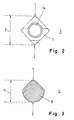
- the proximal end part 3 of the intramedullary nail has a cross-sectional area 7 which is trigonal both in the anterior half 1 and in the posterior half 2 of the intramedullary nail, so that a square profile 7 is present overall in this proximal part.
- the distal end part 4 of the intramedullary nail has a cross-sectional area 8, which is also trigonal in the anterior half 1 - with a tip rounded towards the anterior half 1 - but is semispherical in the posterior half 2.
- proximal end part 3 two medio-lateral locking holes 11 are provided, each of which can receive a locking screw (not shown).
- the distal end part 4 is also provided with two medio-lateral locking holes 12, each of which can receive a locking screw (not shown).
- the proximal end part 3 On its proximal front surface, the proximal end part 3 has a bore 14, which is used to drive the nail in and out using suitable instruments.
- the distal end part 4 has a posteriorly directed step 13 at its tip, which allows easy insertion of the intramedullary nail into the medullary canal by sliding with little resistance along the dorsal inner cortex.
- the profile shown in FIG. 2 corresponds to the situation at the section line II-II in FIG. 1, the maximum diameter 9 measured in the antero-posterior direction of the proximal end part 3 decreases continuously from proximal to distal, preferably from 12 to 13 mm to approximately 8 to 9 mm.
- the profile shown in FIG. 3 corresponds to the situation at the section line III-III in FIG. 1, the maximum diameter 10 of the distal end part 4 measured in the antero-posterior direction remaining essentially constant from proximal to distal.
Abstract
Description
- Die Erfindung bezieht sich auf einen Tibia-Marknagel gemäss Oberbegriff des Anspruchs 1.
- Ein solcher Nagel ist beispielsweise aus der EP-A1 0 332 857 bekannt.
- Für die Versorgung von Unterschenkelfrakturen wird häufig die Marknagelung angewendet. Die Funktion der Marknagelung entspricht einer inneren Schienung des Röhrenknochens. Eine Schienung kann, je nach Methode, aus einem Rohr oder einer Anzahl von Metallstäben (Bündelnagelung) bestehen. Bei der Anwendung eines Rohrnagels, wie sie beispielsweise in der EP-A1 0 332 857 "Tibia-Marknagel zur Behandlung von Unterschenkelfrakturen" beschrieben ist, muss der Markraum des Röhrenknochens durch Auffräsen vorbereitet werden. Durch diesen Auffräsvorgang erreicht man einen Formschluss zwischen Nagel und Knocheninnenwand. Der Knochen ist bei dieser Methode optimal geschient. Die Vorraussetzung zur Anwendung dieser bekannten Methode ist jedoch, dass axiale Kräfte und Torsionskräfte von der Knochenfraktur aufgenommen werden können.
- Das Gleiche gilt für die sogenannte Bündelnagelung, bei welcher der nicht aufgefräste Markraum mit langen Metallstäben aufgefüllt wird. Diese Art der Schienung ist sehr stark vom Geschick des einzelnen Chirurgen abhängig, da es nicht einfach ist, den gesamten Markraumquerschnitt mit diesen Metallstäben zu füllen.
- Ist keine knöcherne Abstützung der Knochenfraktur selbst vorhanden (Trümmerbrüche, Knochendefekte) muss die sogenannte Verriegelungs-Marknagelung vorgenommen werden. Bei dieser ebenfalls bekannten Art der Marknagelung, bedarf es keiner Markraumpassung. Trotzdem muss in den meisten Fällen - ausser bei langen Trümmerzonen - eine Auffräsung des Markraums vorgenommen werden, da verriegelbare Marknägel - bedingt durch ihre Belastung - einen gewissen Durchmesser aufweisen und um einiges steifer sind.
- Rohrförmige Marknägel, beispielsweise gemäss EP-A1 0 332 857, sind in ihrer Form dem aufgefrästen Markraum angepasst.
Rohrnägel ohne Verriegelungsmöglichkeit besitzen üblicherweise einen kleeblattförmigen Querschnitt und sind teilweise oder durchgehend längs geschlitzt. Das hat den Vorteil, dass sich der Nagel im aufgefrästen Markraum radial verspannen kann, wodurch eine erhöhte Stabilität der Fraktur auf einwirkende Rotationskräfte erzielt wird. Dieses Verspannen des Marknagels bedingt jedoch ein masslich exaktes Auffräsen des Markraums, um ein Verklemmen des Marknagels bei dessen Einführung zu verhindern. Bei der Verriegelungsnagelung wird auf die radiale Vorspannung verzichtet, da die Fraktur durch die quer eingebrachten Schrauben (Verriegelung) gesichert ist. Der Querschnitt dieser Marknägel ist deshalb annähernd kreisförmig, damit sie leicht in den aufgefrästen Markraum eingebracht werden können. - Beim Versuch einen rohrförmigen Marknagel in einen nicht aufgefrästen Markraum zu schlagen, bedarf es eines grossen Kraftaufwandes, da der Tibiaquerschnitt nicht dem Querschnitt des Marknagels entspricht. Dabei kann - neben dem Verklemmen des Marknagels - oft ein Bersten des Tibiaschaftes beobachtet werden.
- Um die obengenannten Probleme zu vermeiden, kann zwar ein dünnerer Marknagel gewählt werden, doch ist dies nicht immer möglich, da die mechanische Festigkeit von Rohrnägeln naturgemäss limitiert ist. Diese Festigkeitslimite kann leicht erreicht werden, da diese Art von Marknägel keinerlei rotationshemmende Funktion aufweisen, d.h., dass neben den axial einwirkenden Kräften auch Rotationskräfte vollumfänglich von den Verriegelungsschrauben, bzw. Verriegelungsbolzen aufgenommen werden müssen.
- Hier will die Erfindung Abhilfe schaffen.
Der Erfindung liegt die Aufgabe zugrunde, einen Marknagel zu schaffen für die Behandlung von Unterschenkelfrakturen sämtlicher Indikationen mit einer optimal an die Anatomie der Markhöhle, insbesondere in antero-posteriorer Richtung, angepassten Form.
Insbesondere wird die Aufgabe gelöst einen Tibia-Marknagel zu schaffen, welcher im proximalen, spongiösen Teil der Tibia eine hohe Rotationsstabilität aufweist und im distalen, kortikalen Teil der Tibia eine möglichst optimale Anpassung an die Geometrie der Markraumhöhlung gewährleistet.
Die Erfindung löst die gestellte Aufgabe mit einem Tibia-Marknagel, welcher die Merkmale des Anspruchs 1 aufweist. - Der erfindungsgemässe, in der antero-posterioren Ebene geknickte Tibia-Marknagel weist im proximalen und im distalen Endteil unterschiedlich ausgestaltete Querschnitte auf, um den ebenfalls unterschiedlichen Anforderungen in diesen beiden Bereichen zu genügen. Dazu ist der proximale Endteil mit einer annähernd quadratischen Querschnittsfläche ausgebildet, was die Rotationsstabilität in diesem vorwiegend spongiösen Teil der Tibia verbessert. Der distale Endteil ist auf der anterioren Seite gleich ausgebildet wie der proximale Endteil, hingegen ist er auf der posterioren Seite sphärisch ausgebildet um sich der Markraumanatomie in diesem Bereich besser anpassen zu können.
- Die Längsachsen der beiden in der antero-posterioren Ebene gegeneinander abgeknickten Endteile schliessen einen Winkel α von 5 bis 13°, vorzugsweise von 7 bis 11°, miteinander ein. Auch die absoluten Dimensionen des Marknagels sind in weiten Bereichen - je nach den anatomischen Erfordernissen - variierbar, doch hat es sich als vorteilhaft erwiesen, wenn die Länge des proximalen Endteils 30 - 35 %, vorzugsweise 33 - 34% der Gesamtlänge des Marknagels beträgt.
- Die im distalen Bereich sphärisch ausgebildete, posteriore Seite des Marknagels ermöglicht ein leichtes Eindringen des Implantats, welches dank dieser Formgebung leicht an der posterioren Innenwand der Tibia entlang gleiten kann. Die im distalen Bereich trigonal ausgebildete anteriore Seite des Marknagelquerschnitts entspricht derjenigen des unaufgefrästen Tibiamarkraumquerschnitt in diesem Bereich. Neben der Rotationssicherung hat diese Nagelquerschnittsform den Vorteil, dass ein im Querschnitt grösserer Nagel, als im Vergleich zu einem Nagel mit kreisförmigem Querschnitt, verwendet werden kann. Die Gefahr eines Implantatbruches ist deshalb geringer.
- Der volle Nagelquerschnitt hat grundsätzlich zwei Vorteile. Einerseits entsteht nach der Implantation des Marknagels kein Hohlraum im Markkanal, der bei der Behandlung von offenen Frakturen zu Problemen führen kann. Andererseits wird der Nagelquerschnitt im Bereich der Verriegelungsbohrungen weniger geschwächt. Der im Markraum entstehende Hohlraum kann bei der Verwendung von Rohrnägeln bei der Behandlung von offenen Frakturen zu Problemen führen, da der Körper eventuell eingebrachte Fremdkörper nicht abbauen kann, was zu einem Infektionsrisiko führt.
- Der im Querschnitt angepasste erfindungsgemässe Marknagel kann, dank seiner anatomischen Form, ohne grossen Kraftaufwand in den Markraum eingeschoben werden. Das hat den Vorteil, dass keine zusätzlichen Verletzungen der Tibia, in Bezug auf Weichteilschädigung, Blutversorgung und Fragmentabsprengung, befürchtet werden müssen.
- Ein Ausführungsbeispiel der Erfindung, ist in den Figuren dargestellt und wird im folgenden näher beschrieben.
- Fig. 1 stellt einen sagittalen Längsschnitt durch den erfindungsgemässen Tibia-Marknagel dar;
- Fig. 2 stellt einen Querschnitt längs der Linie II-II in Fig. 1 dar; und
- Fig. 3 stellt einen Querschnitt längs der Linie III-III in Fig. 1 dar.
- Der in Fig. 1 dargestellte Tibia-Marknagel gemäss der Erfindung ist voll aus einem für solche Implantate üblichen metallischen Werkstoff gefertigt. Er weist eine anteriore Seite 1 und eine posteriore Seite 2 auf und besteht im wesentlichen aus einem proximalen Endteil 3 und einem distalen Endteil 4, welche gegeneinander abgewinkelt sind. Die Längsachsen 5 und 6 der beiden Endteile 3 und 4 schliessen in der sagittalen Ebene - welche der Zeichnungsebene entspricht - einen Winkel α von 8° bis 10°, vorzugsweise von 9° ein.
- Der proximale Endteil 3 des Marknagels weist eine Querschnittsfläche 7 auf, welche sowohl in der anterioren Hälfte 1, als auch in der posterioren Hälfte 2 des Marknagels trigonal ausgebildet ist, so dass insgesamt in diesem proximalen Teil ein quadratisches Profil 7 vorliegt.
- Der distale Endteil 4 des Marknagels weist eine Querschnittsfläche 8 auf, welche in der anterioren Hälfte 1 ebenfalls trigonal ausgebildet ist - mit einer gegen die anteriore Hälfte 1 hin abgerundeten Spitze - in der posterioren Hälfte 2 jedoch semisphärisch geformt ist.
- Im proximalen Endteil 3 sind zwei medio-lateral verlaufende Verriegelungslöcher 11 vorgesehen, welche je eine (nicht dargestellte) Verriegelung-Schraube aufnehmen können. Auch der distale Endteil 4 ist mit zwei medio-lateral verlaufenden Verriegelungslöchern 12 versehen, welche je eine (nicht dargestellte) Verriegelungs-Schraube aufnehmen können.
- An seiner proximalen Frontfläche besitzt der proximale Endteil 3 eine Bohrung 14, welche zum Ein- und Ausschlagen des Marknagels mittels dazu geeigneter Instrumente dient.
- Schliesslich weist der distale Endteil 4 an seiner Spitze eine nach posterior gerichtete Abstufung 13 auf, welche die problemlose Insertion des Marknagels in den Markraum durch widerstandsarmes Gleiten entlang der dorsalen inneren Kortikalis gestattet.
- In den Fig. 2 und 3 sind die unterschiedlichen Querschnittsprofile im proximalen 3 und distalen 4 Endteil des Marknagels dargestellt. Das in Fig. 2 gezeigte Profil entspricht der Situation auf Höhe der Schnittlinie II-II in Fig. 1, wobei der in antero-posteriorer Richtung gemessene, maximale Durchmesser 9 des proximalen Endteils 3 von proximal nach distal kontinuierlich abnimmt, vorzugsweise von 12 bis 13 mm auf etwa 8 bis 9 mm.
Das in Fig. 3 gezeigte Profil entspricht der Situation auf Höhe der Schnittlinie III-III in Fig. 1, wobei der in antero-posteriorer Richtung gemessene, maximale Durchmesser 10 des distalen Endteils 4 von proximal nach distal im wesentlichen konstant bleibt.
Claims (11)
- Tibia-Marknagel mit einer anterioren Hälfte (1), einer posterioren Hälfte (2), einem proximalen Endteil (3) und einem distalen Endteil (4), wobei die Längsachsen (5;6) der beiden Endteile (3;4) in der antero-posterioren Ebene einen Winkel von 5 bis 13° miteinander einschliessen, dadurch gekennzeichnet, dass der proximale Endteil (3) eine Querschnittsfläche (7) aufweist, welche sowohl in der anterioren (1), als auch in der posterioren (2) Hälfte trigonal ausgebildet ist und gesamthaft annähernd quadratisch ist, und dass der distale Endteil (4) eine Querschnittsfläche (8) aufweist, welche in der anterioren Hälfte (1) annähernd trigonal und in der posterioren Hälfte (2) annähernd semisphärisch ist.
- Tibia-Marknagel nach Anspruch 1, dadurch gekennzeichnet, dass die trigonal ausgebildete, anteriore Querschnittsfläche (8) gegen anterior (1) abgerundet ist.
- Tibia-Marknagel nach Anspruch 1 oder 2, dadurch gekennzeichnet, dass die Länge des proximalen Endteils (3) 30 - 35 %, vorzugsweise 33 - 34% der Gesamtlänge des Marknagels beträgt.
- Tibia-Marknagel nach einem der Ansprüche 1 bis 3, dadurch gekennzeichnet, dass der in antero-posterioren Richtung gemessene, maximale Durchmesser (9) des proximalen Endteils (3) von proximal nach distal kontinuierlich abnimmt, vorzugsweise von 12 bis 13 mm auf 8 bis 9 mm.
- Tibia-Marknagel nach einem der Ansprüche 1 bis 4, dadurch gekennzeichnet, dass der in antero-posteriorer Richtung gemessene, maximale Durchmesser (10) des distalen Endteils (4) von proximal nach distal im wesentlichen konstant bleibt.
- Tibia-Marknagel nach einem der Ansprüche 1 bis 5, dadurch gekennzeichnet, dass der proximale Endteil (3) mindestens ein, vorzugsweise zwei Verriegelungslöcher (11) aufweist.
- Tibia-Marknagel nach einem der Ansprüche 1 bis 6, dadurch gekennzeichnet, dass der distale Endteil (4) mindestens ein, vorzugsweise zwei Verriegelungslöcher (12) aufweist.
- Tibia-Marknagel nach Anspruch 6 oder 7, dadurch gekennzeichnet, dass die Verriegelungslöcher (11;12) in medio-lateraler Richtung verlaufen.
- Tibia-Marknagel nach einem der Ansprüche 1 bis 8, dadurch gekennzeichnet, dass der Marknagel voll ausgebildet ist.
- Tibia-Marknagel nach einem der Ansprüche 1 bis 9, dadurch gekennzeichnet, dass der distale Endteil (4) an seiner Spitze eine nach posterior gerichtete Abstufung (13) aufweist.
- Tibia-Marknagel nach einem der Ansprüche 1 bis 10, dadurch gekennzeichnet, dass die Längsachsen (5;6) der beiden Endteile (3;4) in der antero-posterioren Ebene einen Winkel von 7 bis 11°, vorzugsweise von 8 bis 10° miteinander einschliessen.
Applications Claiming Priority (2)
| Application Number | Priority Date | Filing Date | Title |
|---|---|---|---|
| CH914/90 | 1990-03-20 | ||
| CH914/90A CH683065A5 (de) | 1990-03-20 | 1990-03-20 | Tibia-Marknagel mit angepasstem Querschnitt. |
Publications (2)
| Publication Number | Publication Date |
|---|---|
| EP0447824A1 true EP0447824A1 (de) | 1991-09-25 |
| EP0447824B1 EP0447824B1 (de) | 1995-07-26 |
Family
ID=4198113
Family Applications (1)
| Application Number | Title | Priority Date | Filing Date |
|---|---|---|---|
| EP91102448A Expired - Lifetime EP0447824B1 (de) | 1990-03-20 | 1991-02-20 | Tibia-Marknagel mit angepasstem Querschnitt |
Country Status (6)
| Country | Link |
|---|---|
| US (1) | US5035697A (de) |
| EP (1) | EP0447824B1 (de) |
| JP (1) | JPH0624536B2 (de) |
| AT (1) | ATE125437T1 (de) |
| CH (1) | CH683065A5 (de) |
| DE (1) | DE59106063D1 (de) |
Cited By (4)
| Publication number | Priority date | Publication date | Assignee | Title |
|---|---|---|---|---|
| AT399649B (de) * | 1993-05-17 | 1995-06-26 | Ender Hans Georg | Knochennagel |
| DE4341677C1 (de) * | 1993-12-07 | 1995-07-13 | Endocare Ag | Verriegelungsnagel |
| WO1999020195A1 (de) * | 1997-10-20 | 1999-04-29 | Synthes Ag Chur | Knochenfixationsvorrichtung |
| WO1999035989A1 (de) * | 1998-01-19 | 1999-07-22 | Hans Habernek | Universell anwendbarer marknagel mit zugehörigem zielgerät |
Families Citing this family (95)
| Publication number | Priority date | Publication date | Assignee | Title |
|---|---|---|---|---|
| EP0534152B1 (de) * | 1991-09-26 | 1996-11-06 | United States Surgical Corporation | Vorrichtung zum Reparieren von Nerven |
| DE9115201U1 (de) * | 1991-12-07 | 1992-02-06 | Howmedica Gmbh, 2314 Schoenkirchen, De | |
| US5179915A (en) * | 1992-01-06 | 1993-01-19 | Osteonics Corporation | Anatomically matching intramedullary alignment rod |
| US5505733A (en) * | 1993-10-22 | 1996-04-09 | Justin; Daniel F. | Intramedullary skeletal distractor and method |
| US5472444A (en) * | 1994-05-13 | 1995-12-05 | Acumed, Inc. | Humeral nail for fixation of proximal humeral fractures |
| DE29615482U1 (de) * | 1996-09-05 | 1998-01-08 | Howmedica Gmbh | Suprakondylarer Knochennagel |
| IT1293934B1 (it) * | 1997-01-21 | 1999-03-11 | Orthofix Srl | Chiodo endomidollare per il trattamento delle fratture dell'anca |
| US6336929B1 (en) | 1998-01-05 | 2002-01-08 | Orthodyne, Inc. | Intramedullary skeletal distractor and method |
| EP0976365A1 (de) * | 1998-07-27 | 2000-02-02 | Osteo Ag | Retrograder Tibianagel |
| US6120504A (en) * | 1998-12-10 | 2000-09-19 | Biomet Inc. | Intramedullary nail having dual distal bore formation |
| DE60009705D1 (de) * | 1999-05-27 | 2004-05-13 | Jonathan Phillips | Pädiatrischer intramedullärer marknagel |
| US7008425B2 (en) | 1999-05-27 | 2006-03-07 | Jonathan Phillips | Pediatric intramedullary nail and method |
| US6706046B2 (en) | 2000-02-01 | 2004-03-16 | Hand Innovations, Inc. | Intramedullary fixation device for metaphyseal long bone fractures and methods of using the same |
| US6730090B2 (en) | 2000-02-01 | 2004-05-04 | Hand Innovations, Inc. | Fixation device for metaphyseal long bone fractures |
| US6767351B2 (en) | 2000-02-01 | 2004-07-27 | Hand Innovations, Inc. | Fixation system with multidirectional stabilization pegs |
| US20060041260A1 (en) * | 2000-02-01 | 2006-02-23 | Orbay Jorge L | Fixation system with plate having holes with divergent axes and multidirectional fixators for use therethrough |
| US7857838B2 (en) | 2003-03-27 | 2010-12-28 | Depuy Products, Inc. | Anatomical distal radius fracture fixation plate |
| US7695502B2 (en) | 2000-02-01 | 2010-04-13 | Depuy Products, Inc. | Bone stabilization system including plate having fixed-angle holes together with unidirectional locking screws and surgeon-directed locking screws |
| US20040153073A1 (en) | 2000-02-01 | 2004-08-05 | Hand Innovations, Inc. | Orthopedic fixation system including plate element with threaded holes having divergent axes |
| US6527775B1 (en) | 2000-09-22 | 2003-03-04 | Piper Medical, Inc. | Intramedullary interlocking fixation device for the distal radius |
| US20060149257A1 (en) * | 2002-05-30 | 2006-07-06 | Orbay Jorge L | Fracture fixation device |
| US7938850B2 (en) | 2002-05-30 | 2011-05-10 | Depuy Products, Inc. | Nail plate |
| US7425213B2 (en) | 2002-12-10 | 2008-09-16 | Depuy Products, Inc. | Method of endosteal nailing |
| US7635365B2 (en) | 2003-08-28 | 2009-12-22 | Ellis Thomas J | Bone plates |
| CA2545487C (en) * | 2003-10-21 | 2012-05-01 | Synthes (U.S.A.) | Intramedullary nail |
| EP1691700B1 (de) | 2003-12-01 | 2012-01-11 | Smith & Nephew, Inc. | Humerusnagel mit Einsatz zum Fixieren einer Schraube |
| WO2005079676A1 (en) * | 2004-02-23 | 2005-09-01 | Synthes Ag Chur | Intramedullary nail |
| WO2005096977A1 (en) * | 2004-04-12 | 2005-10-20 | Navin Thakkar | An implant assembly for proximal femoral fracture |
| US7632284B2 (en) * | 2004-07-06 | 2009-12-15 | Tyco Healthcare Group Lp | Instrument kit and method for performing meniscal repair |
| US20060015101A1 (en) | 2004-07-15 | 2006-01-19 | Wright Medical Technology, Inc. | Intramedullary fixation assembly and devices and methods for installing the same |
| US7588577B2 (en) | 2004-07-15 | 2009-09-15 | Wright Medical Technology, Inc. | Guide assembly for intramedullary fixation and method of using the same |
| US9662158B2 (en) | 2004-08-09 | 2017-05-30 | Si-Bone Inc. | Systems and methods for the fixation or fusion of bone at or near a sacroiliac joint |
| US8414648B2 (en) * | 2004-08-09 | 2013-04-09 | Si-Bone Inc. | Apparatus, systems, and methods for achieving trans-iliac lumbar fusion |
| US8425570B2 (en) | 2004-08-09 | 2013-04-23 | Si-Bone Inc. | Apparatus, systems, and methods for achieving anterior lumbar interbody fusion |
| US8388667B2 (en) | 2004-08-09 | 2013-03-05 | Si-Bone, Inc. | Systems and methods for the fixation or fusion of bone using compressive implants |
| US20070156241A1 (en) | 2004-08-09 | 2007-07-05 | Reiley Mark A | Systems and methods for the fixation or fusion of bone |
| US8444693B2 (en) * | 2004-08-09 | 2013-05-21 | Si-Bone Inc. | Apparatus, systems, and methods for achieving lumbar facet fusion |
| US20060036251A1 (en) | 2004-08-09 | 2006-02-16 | Reiley Mark A | Systems and methods for the fixation or fusion of bone |
| US8470004B2 (en) | 2004-08-09 | 2013-06-25 | Si-Bone Inc. | Apparatus, systems, and methods for stabilizing a spondylolisthesis |
| US9949843B2 (en) | 2004-08-09 | 2018-04-24 | Si-Bone Inc. | Apparatus, systems, and methods for the fixation or fusion of bone |
| US20180228621A1 (en) | 2004-08-09 | 2018-08-16 | Mark A. Reiley | Apparatus, systems, and methods for the fixation or fusion of bone |
| CA2594179C (en) * | 2004-12-31 | 2012-08-28 | Synthes Gmbh | Intramedullary nail |
| US7896886B2 (en) * | 2005-01-28 | 2011-03-01 | Depuy Products, Inc. | Nail plate and implantation jig therefor |
| US7410488B2 (en) | 2005-02-18 | 2008-08-12 | Smith & Nephew, Inc. | Hindfoot nail |
| US9060820B2 (en) | 2005-05-18 | 2015-06-23 | Sonoma Orthopedic Products, Inc. | Segmented intramedullary fracture fixation devices and methods |
| US8287541B2 (en) | 2005-05-18 | 2012-10-16 | Sonoma Orthopedic Products, Inc. | Fracture fixation device, tools and methods |
| US8961516B2 (en) | 2005-05-18 | 2015-02-24 | Sonoma Orthopedic Products, Inc. | Straight intramedullary fracture fixation devices and methods |
| CA2608693A1 (en) | 2005-05-18 | 2006-11-23 | Sonoma Orthopedic Products, Inc. | Minimally invasive actuable bone fixation devices, systems and methods of use |
| US7905909B2 (en) | 2005-09-19 | 2011-03-15 | Depuy Products, Inc. | Bone stabilization system including multi-directional threaded fixation element |
| AU2006304847B2 (en) * | 2005-10-21 | 2011-09-15 | Acumed Llc | Orthopedic rod with locking aperture |
| US20070173835A1 (en) * | 2006-01-13 | 2007-07-26 | Medoff Robert J | Intramedullary implant for fracture fixation and method of using the same |
| US8075634B2 (en) * | 2006-04-11 | 2011-12-13 | Eli Hurowitz | Orthopedic device |
| AU2007323566A1 (en) | 2006-11-22 | 2008-05-29 | Sonoma Orthopedic Products, Inc. | Fracture fixation device, tools and methods |
| US7722611B2 (en) * | 2007-03-05 | 2010-05-25 | Depuy Products, Inc. | Method of treating a clavicle fracture |
| US8430879B2 (en) | 2007-03-22 | 2013-04-30 | Sonoma Orthopedic Products, Inc. | Segmented intramedullary structure |
| US9597129B2 (en) * | 2007-05-25 | 2017-03-21 | Zimmer Gmbh | Reinforced intramedullary nail |
| US9375241B2 (en) | 2007-11-26 | 2016-06-28 | Biedermann Technologies Gmbh & Co. Kg | Bone nail for the heel |
| US8771283B2 (en) | 2007-12-17 | 2014-07-08 | Wright Medical Technology, Inc. | Guide assembly for intramedullary fixation and method of using the same |
| FR2927792A1 (fr) * | 2008-02-25 | 2009-08-28 | Dominique Persoons | Clou radial percutane. |
| US8414584B2 (en) * | 2008-07-09 | 2013-04-09 | Icon Orthopaedic Concepts, Llc | Ankle arthrodesis nail and outrigger assembly |
| WO2010006195A1 (en) * | 2008-07-09 | 2010-01-14 | Amei Technologies, Inc. | Ankle arthrodesis nail and outrigger assembly |
| EP2341857A2 (de) | 2008-09-26 | 2011-07-13 | Sonoma Orthopedic Products, Inc. | Knochenfixierungsvorrichtung, -werkzeuge und -verfahren |
| JP5497194B2 (ja) * | 2009-12-11 | 2014-05-21 | スモール・ボーン・イノベーションズ・インコーポレーテッド | 足首癒合デバイス、器具、および方法 |
| US8568417B2 (en) | 2009-12-18 | 2013-10-29 | Charles River Engineering Solutions And Technologies, Llc | Articulating tool and methods of using |
| DE102010023640B4 (de) | 2010-06-14 | 2015-04-09 | Bernhard Clasbrummel | Nagel-Schrauben-System für winkelstabile Osteosynthese |
| DE102010048052B4 (de) | 2010-10-12 | 2015-06-25 | Bernhard Clasbrummel | Nagel-Schrauben-System für eine Osteosynthese |
| GB2558433B (en) | 2011-09-30 | 2018-12-12 | Acute Innovations Llc | Bone fixation system with opposed mounting portions |
| JP5345193B2 (ja) * | 2011-10-13 | 2013-11-20 | 京セラメディカル株式会社 | 大腿骨近位部骨折用固定器具 |
| WO2013113015A1 (en) | 2012-01-26 | 2013-08-01 | Acute Innovations Llc | Clip for rib stabilization |
| US8778026B2 (en) | 2012-03-09 | 2014-07-15 | Si-Bone Inc. | Artificial SI joint |
| IN2014DN06946A (de) | 2012-03-09 | 2015-04-10 | Si Bone Inc | |
| US10363140B2 (en) | 2012-03-09 | 2019-07-30 | Si-Bone Inc. | Systems, device, and methods for joint fusion |
| JP6629068B2 (ja) | 2012-05-04 | 2020-01-15 | エスアイ−ボーン・インコーポレイテッドSi−Bone, Inc. | 有窓のインプラント |
| US11051864B2 (en) | 2012-08-30 | 2021-07-06 | DePuy Synthes Products, Inc. | Intramedullary fixation assembly |
| EP2732783B1 (de) * | 2012-11-14 | 2016-04-27 | Biedermann Technologies GmbH & Co. KG | Knochennagel für die Ferse |
| WO2014145902A1 (en) | 2013-03-15 | 2014-09-18 | Si-Bone Inc. | Implants for spinal fixation or fusion |
| US9782205B2 (en) * | 2013-07-02 | 2017-10-10 | Cmarr Enterprises, Llc | Curved tibiotalar fusion nail and method of use |
| US11147688B2 (en) | 2013-10-15 | 2021-10-19 | Si-Bone Inc. | Implant placement |
| WO2015057866A1 (en) | 2013-10-15 | 2015-04-23 | Si-Bone Inc. | Implant placement |
| US9770278B2 (en) | 2014-01-17 | 2017-09-26 | Arthrex, Inc. | Dual tip guide wire |
| JP6542362B2 (ja) | 2014-09-18 | 2019-07-10 | エスアイ−ボーン・インコーポレイテッドSi−Bone, Inc. | マトリックス・インプラント |
| WO2016044731A1 (en) | 2014-09-18 | 2016-03-24 | Si-Bone Inc. | Implants for bone fixation or fusion |
| US9814499B2 (en) | 2014-09-30 | 2017-11-14 | Arthrex, Inc. | Intramedullary fracture fixation devices and methods |
| US10376206B2 (en) | 2015-04-01 | 2019-08-13 | Si-Bone Inc. | Neuromonitoring systems and methods for bone fixation or fusion procedures |
| WO2017117263A1 (en) * | 2015-12-28 | 2017-07-06 | Glenhurst Labs, Llc | Surgical devices for small bone fracture surgery |
| KR101722252B1 (ko) * | 2016-03-18 | 2017-04-03 | 이동훈 | 틸팅 방지 기능을 갖는 골수강 네일 |
| US11116519B2 (en) | 2017-09-26 | 2021-09-14 | Si-Bone Inc. | Systems and methods for decorticating the sacroiliac joint |
| US11426220B2 (en) | 2017-10-11 | 2022-08-30 | Howmedica Osteonics Corp. | Humeral fixation plate guides |
| FR3077476B1 (fr) * | 2018-02-07 | 2022-10-21 | In2Bones | Dispositif d'arthrodese ameliore |
| US11369419B2 (en) | 2019-02-14 | 2022-06-28 | Si-Bone Inc. | Implants for spinal fixation and or fusion |
| EP3923829A4 (de) | 2019-02-14 | 2022-12-14 | SI-Bone, Inc. | Implantate zur wirbelsäulenfixation und/oder -fusion |
| WO2021108590A1 (en) | 2019-11-27 | 2021-06-03 | Si-Bone, Inc. | Bone stabilizing implants and methods of placement across si joints |
| WO2021240242A1 (en) | 2020-05-29 | 2021-12-02 | Stryker European Operations Limited | Funnel hole for intramedullary nail |
| TR202017292A1 (tr) * | 2020-10-30 | 2022-05-23 | Tst Rakor Ve Tibbi Aletler Sanayi Ve Ticaret Ltd Sirketi | Artrodez çi̇vi̇si̇ |
| AU2021397743A1 (en) | 2020-12-09 | 2023-06-22 | Si-Bone Inc. | Sacro-iliac joint stabilizing implants and methods of implantation |
Citations (3)
| Publication number | Priority date | Publication date | Assignee | Title |
|---|---|---|---|---|
| EP0094489A2 (de) * | 1982-05-18 | 1983-11-23 | HOWMEDICA INTERNATIONAL, INC. Zweigniederlassung Kiel | Knochennagel zur Versorgung von Frakturen im proximalen Oberschenkelbereich und zugehöriges Instrumentarium |
| DE8907443U1 (de) * | 1989-06-19 | 1989-09-14 | Aesculap Ag, 7200 Tuttlingen, De | |
| EP0332857A1 (de) * | 1988-03-14 | 1989-09-20 | Synthes Ag Chur | Tibia-Marknagel zur Behandlung von Unterschenkelfrakturen |
Family Cites Families (7)
| Publication number | Priority date | Publication date | Assignee | Title |
|---|---|---|---|---|
| FR1031128A (fr) * | 1951-01-18 | 1953-06-19 | Perfectionnements apportés aux instruments d'ostéosynthèse dits <<clous médullaires>> | |
| CA987983A (en) * | 1972-10-24 | 1976-04-27 | William X. Halloran | Combination intramedullary fixation and external bone compression apparatus |
| US4589883A (en) * | 1983-06-06 | 1986-05-20 | Pfizer Hospital Products Group, Inc. | Femoral hip prosthesis |
| JPS6017708U (ja) * | 1983-07-13 | 1985-02-06 | 宮田 敬三 | 骨折した長管骨の髄内固定用の金具 |
| US4678471A (en) * | 1985-08-22 | 1987-07-07 | Noble Philip C | Method and apparatus for preventing rotational failure of orthopedic endoprostheses |
| JPS6368155A (ja) * | 1986-09-11 | 1988-03-28 | グンゼ株式会社 | 骨接合ピン |
| US4846162A (en) * | 1987-09-14 | 1989-07-11 | Moehring H David | Orthopedic nail and method of bone fracture fixation |
-
1990
- 1990-03-20 CH CH914/90A patent/CH683065A5/de not_active IP Right Cessation
- 1990-07-03 US US07/547,238 patent/US5035697A/en not_active Expired - Lifetime
-
1991
- 1991-02-20 DE DE59106063T patent/DE59106063D1/de not_active Expired - Lifetime
- 1991-02-20 EP EP91102448A patent/EP0447824B1/de not_active Expired - Lifetime
- 1991-02-20 AT AT91102448T patent/ATE125437T1/de not_active IP Right Cessation
- 1991-03-19 JP JP3078300A patent/JPH0624536B2/ja not_active Expired - Fee Related
Patent Citations (3)
| Publication number | Priority date | Publication date | Assignee | Title |
|---|---|---|---|---|
| EP0094489A2 (de) * | 1982-05-18 | 1983-11-23 | HOWMEDICA INTERNATIONAL, INC. Zweigniederlassung Kiel | Knochennagel zur Versorgung von Frakturen im proximalen Oberschenkelbereich und zugehöriges Instrumentarium |
| EP0332857A1 (de) * | 1988-03-14 | 1989-09-20 | Synthes Ag Chur | Tibia-Marknagel zur Behandlung von Unterschenkelfrakturen |
| DE8907443U1 (de) * | 1989-06-19 | 1989-09-14 | Aesculap Ag, 7200 Tuttlingen, De |
Cited By (5)
| Publication number | Priority date | Publication date | Assignee | Title |
|---|---|---|---|---|
| AT399649B (de) * | 1993-05-17 | 1995-06-26 | Ender Hans Georg | Knochennagel |
| DE4341677C1 (de) * | 1993-12-07 | 1995-07-13 | Endocare Ag | Verriegelungsnagel |
| WO1999020195A1 (de) * | 1997-10-20 | 1999-04-29 | Synthes Ag Chur | Knochenfixationsvorrichtung |
| US6270499B1 (en) | 1997-10-20 | 2001-08-07 | Synthes (U.S.A.) | Bone fixation device |
| WO1999035989A1 (de) * | 1998-01-19 | 1999-07-22 | Hans Habernek | Universell anwendbarer marknagel mit zugehörigem zielgerät |
Also Published As
| Publication number | Publication date |
|---|---|
| JPH0624536B2 (ja) | 1994-04-06 |
| ATE125437T1 (de) | 1995-08-15 |
| US5035697A (en) | 1991-07-30 |
| CH683065A5 (de) | 1994-01-14 |
| JPH04221548A (ja) | 1992-08-12 |
| EP0447824B1 (de) | 1995-07-26 |
| DE59106063D1 (de) | 1995-08-31 |
Similar Documents
| Publication | Publication Date | Title |
|---|---|---|
| EP0447824B1 (de) | Tibia-Marknagel mit angepasstem Querschnitt | |
| DE602004007219T2 (de) | Implantierbare Orthese und chirurgischer Satz für eine Arthrodese des Knies | |
| AT507086B1 (de) | Implantat, insbesondere marknagel für die behandlung einer proximalen humerusfraktur | |
| EP1024762B1 (de) | Knochenfixationsvorrichtung | |
| EP0491138B1 (de) | Vorrichtung zur Fixation von Knochenbrüchen | |
| DE19619093B4 (de) | Marknagelsystem zur Frakturheilung bzw. Knochenverlängerung | |
| EP1890620B1 (de) | Vorrichtung für die osteosynthese | |
| DE69934516T2 (de) | Axiale intrameduläre schraube zur osteosynthese von langen knochen | |
| AT398529B (de) | Endoprothese, insbesondere des hüftgelenkes | |
| EP1100389B1 (de) | Retrograder tibianagel | |
| EP2014262B1 (de) | Gelenkteilprothese mit spreizbarem Schaft | |
| DE2605180A1 (de) | Orthopaedischer endoapparat zum aufziehen eines neuen lebenden schulterund hueftgelenks, zur nachbesserung eines formveraenderten oder zur wiederherstellung eines dysplastischen pathologisch veraenderten und angeboren luxierten gelenks | |
| DE102015107056B4 (de) | Arthrodesen-Implantat | |
| EP0617933B1 (de) | Hüftgelenksprothese | |
| CH674613A5 (de) | ||
| DE102008039241A1 (de) | Instrumentarium zur Durchführung eines Operationsverfahrens an einem Gelenk | |
| EP1131008A1 (de) | Markraumnagel zur operativen behandlung von unterarmfrakturen | |
| EP2593042B1 (de) | Fingergelenkprothese | |
| DE19722389A1 (de) | Modulares Knie-Arthrodeseimplantat | |
| DE102008020199B4 (de) | Prothesenraspel | |
| CH664686A5 (en) | Elbow joint prosthesis - has head parts of prosthesis anchored in bone cavities by perforated tubes | |
| AT502137B1 (de) | Primärschaft für eine hüftgelenksprothese | |
| DE2555717C3 (de) | Trochanterplatte für Hüftgelenkendoprothesen | |
| DE3537318A1 (de) | Gleitschlitznagel zur verriegelung von knochenbruechen | |
| DE19743048A1 (de) | Vorrichtung zur Behandlung von Knochenfrakturen |
Legal Events
| Date | Code | Title | Description |
|---|---|---|---|
| PUAI | Public reference made under article 153(3) epc to a published international application that has entered the european phase |
Free format text: ORIGINAL CODE: 0009012 |
|
| 17P | Request for examination filed |
Effective date: 19910220 |
|
| AK | Designated contracting states |
Kind code of ref document: A1 Designated state(s): AT BE DE FR GB |
|
| 17Q | First examination report despatched |
Effective date: 19941229 |
|
| GRAA | (expected) grant |
Free format text: ORIGINAL CODE: 0009210 |
|
| AK | Designated contracting states |
Kind code of ref document: B1 Designated state(s): AT BE DE FR GB |
|
| REF | Corresponds to: |
Ref document number: 125437 Country of ref document: AT Date of ref document: 19950815 Kind code of ref document: T |
|
| ET | Fr: translation filed | ||
| REF | Corresponds to: |
Ref document number: 59106063 Country of ref document: DE Date of ref document: 19950831 |
|
| GBT | Gb: translation of ep patent filed (gb section 77(6)(a)/1977) |
Effective date: 19950809 |
|
| PLBE | No opposition filed within time limit |
Free format text: ORIGINAL CODE: 0009261 |
|
| STAA | Information on the status of an ep patent application or granted ep patent |
Free format text: STATUS: NO OPPOSITION FILED WITHIN TIME LIMIT |
|
| 26N | No opposition filed | ||
| REG | Reference to a national code |
Ref country code: GB Ref legal event code: IF02 |
|
| PGFP | Annual fee paid to national office [announced via postgrant information from national office to epo] |
Ref country code: BE Payment date: 20060310 Year of fee payment: 16 |
|
| REG | Reference to a national code |
Ref country code: GB Ref legal event code: 732E |
|
| REG | Reference to a national code |
Ref country code: FR Ref legal event code: TP |
|
| BERE | Be: lapsed |
Owner name: *SYNTHES G.M.B.H. Effective date: 20070228 |
|
| PG25 | Lapsed in a contracting state [announced via postgrant information from national office to epo] |
Ref country code: BE Free format text: LAPSE BECAUSE OF NON-PAYMENT OF DUE FEES Effective date: 20070228 |
|
| PGFP | Annual fee paid to national office [announced via postgrant information from national office to epo] |
Ref country code: FR Payment date: 20100223 Year of fee payment: 20 |
|
| PGFP | Annual fee paid to national office [announced via postgrant information from national office to epo] |
Ref country code: AT Payment date: 20100212 Year of fee payment: 20 Ref country code: GB Payment date: 20100202 Year of fee payment: 20 Ref country code: DE Payment date: 20100303 Year of fee payment: 20 |
|
| REG | Reference to a national code |
Ref country code: DE Ref legal event code: R071 Ref document number: 59106063 Country of ref document: DE |
|
| REG | Reference to a national code |
Ref country code: GB Ref legal event code: PE20 Expiry date: 20110219 |
|
| PG25 | Lapsed in a contracting state [announced via postgrant information from national office to epo] |
Ref country code: GB Free format text: LAPSE BECAUSE OF EXPIRATION OF PROTECTION Effective date: 20110219 |
|
| PG25 | Lapsed in a contracting state [announced via postgrant information from national office to epo] |
Ref country code: DE Free format text: LAPSE BECAUSE OF EXPIRATION OF PROTECTION Effective date: 20110220 |