EP0447835A2 - Heat removal apparatus for liquid cooled semiconductor modules - Google Patents
Heat removal apparatus for liquid cooled semiconductor modules Download PDFInfo
- Publication number
- EP0447835A2 EP0447835A2 EP91102685A EP91102685A EP0447835A2 EP 0447835 A2 EP0447835 A2 EP 0447835A2 EP 91102685 A EP91102685 A EP 91102685A EP 91102685 A EP91102685 A EP 91102685A EP 0447835 A2 EP0447835 A2 EP 0447835A2
- Authority
- EP
- European Patent Office
- Prior art keywords
- channels
- plate
- inlet
- heat removal
- removal apparatus
- Prior art date
- Legal status (The legal status is an assumption and is not a legal conclusion. Google has not performed a legal analysis and makes no representation as to the accuracy of the status listed.)
- Withdrawn
Links
Images


Classifications
-
- H—ELECTRICITY
- H01—ELECTRIC ELEMENTS
- H01L—SEMICONDUCTOR DEVICES NOT COVERED BY CLASS H10
- H01L23/00—Details of semiconductor or other solid state devices
- H01L23/34—Arrangements for cooling, heating, ventilating or temperature compensation ; Temperature sensing arrangements
- H01L23/42—Fillings or auxiliary members in containers or encapsulations selected or arranged to facilitate heating or cooling
- H01L23/433—Auxiliary members in containers characterised by their shape, e.g. pistons
- H01L23/4336—Auxiliary members in containers characterised by their shape, e.g. pistons in combination with jet impingement
-
- F—MECHANICAL ENGINEERING; LIGHTING; HEATING; WEAPONS; BLASTING
- F28—HEAT EXCHANGE IN GENERAL
- F28F—DETAILS OF HEAT-EXCHANGE AND HEAT-TRANSFER APPARATUS, OF GENERAL APPLICATION
- F28F3/00—Plate-like or laminated elements; Assemblies of plate-like or laminated elements
- F28F3/12—Elements constructed in the shape of a hollow panel, e.g. with channels
-
- F—MECHANICAL ENGINEERING; LIGHTING; HEATING; WEAPONS; BLASTING
- F28—HEAT EXCHANGE IN GENERAL
- F28F—DETAILS OF HEAT-EXCHANGE AND HEAT-TRANSFER APPARATUS, OF GENERAL APPLICATION
- F28F2210/00—Heat exchange conduits
- F28F2210/02—Heat exchange conduits with particular branching, e.g. fractal conduit arrangements
-
- F—MECHANICAL ENGINEERING; LIGHTING; HEATING; WEAPONS; BLASTING
- F28—HEAT EXCHANGE IN GENERAL
- F28F—DETAILS OF HEAT-EXCHANGE AND HEAT-TRANSFER APPARATUS, OF GENERAL APPLICATION
- F28F2210/00—Heat exchange conduits
- F28F2210/10—Particular layout, e.g. for uniform temperature distribution
-
- H—ELECTRICITY
- H01—ELECTRIC ELEMENTS
- H01L—SEMICONDUCTOR DEVICES NOT COVERED BY CLASS H10
- H01L2924/00—Indexing scheme for arrangements or methods for connecting or disconnecting semiconductor or solid-state bodies as covered by H01L24/00
- H01L2924/0001—Technical content checked by a classifier
- H01L2924/0002—Not covered by any one of groups H01L24/00, H01L24/00 and H01L2224/00
Definitions
- This invention relates to cross-hatch flow distribution for liquid cooling of semiconductor modules.
- FIG. 1 shows a cross-sectional view of a prior art thermal conduction module 10 for providing cooling of the integrated circuit chips 12 contained therein.
- the power consumed in the circuits within the chips 12 generates heat which must be removed.
- the chips 12 may have different power requirements and different ranges of operating temperatures.
- the cooling must be of such character as to maintain the temperature of each chip within its required operating range.
- the chips 12 are mounted (by way of solder balls 28) on one side of a substrate 14, generally made of ceramic, which has pins 16 extending from the other side thereof. These connecting pins 16 provide for the plugging of the module into a board (not shown) which may carry auxiliary circuits, etc.
- a housing or cap 18 is attached to the substrate 14 by means of a flange 20 which extends from the periphery of the substrate 14 to the cap 18.
- the cap 18 is made of a good heat conductive material such as copper or aluminum.
- the cap has small cylindrical openings 22 located therein, which are arranged in a matrix directly adjacent to the exposed surface of each chip 12.
- Each of the openings 22 receives a spring loaded pin piston 24.
- Each piston 24 has a square header 26 which contacts the chip surface. Heat generated by the chips 12 is carried away by the pistons 24 to the cap 18.
- coolant for example chilled water
- FIG. 2 shows a top-cutaway view of a prior art cold plate 200 having a serpentine coolant flow path 202 between an inlet 203 and an outlet 204.
- a number of bolt holes 205 are provided for attaching the cold plate to the cap of a thermal conduction module.
- the serpentine coolant flow path is generally serial.
- a single stream of coolant carries away heat from the chips as it passes over the pistons on its way from the inlet 203 to the outlet 204.
- the rate of water flow must substantially be increased.
- FIG. 3 shows an example of another prior art cold plate 300 that uses fins for improved heat transfer.
- Four fins 302 extend from two opposite walls of the cold plate to form a sinuous path for water flow.
- Each parallel segment of the path is relatively wide and is further divided into four parallel channels by a three by three parallel line of short fins 304.
- the gaps between the short fins increase the turbulence in the water flow.
- the parallel channels provide increased fin area with lower flow resistance. While the embodiment of FIG. 3 is an improvement over that of FIG. 2, the coolant is still forced to flow along an essentially serial path over the pins of the TCM. Further, as the number of fins is increased the pressure drop required to maintain sufficient cooling is increased as well.
- the invention as claimed is intended to remedy these drawbacks. It is therefore an object of the invention to enhance removing of heat from integrated circuits having high power dissipations.
- a cold plate having a cross-hatch flow distribution scheme comprising two sets of nonplaner channels which are disposed angularly to each other.
- the first set of channels is formed on a base plate while the second, set is formed on a distribution plate.
- the base and distribution plates are separated by an interposer to improve and customize cold plate performance.
- a heat removal apparatus including a body having a top portion, a central portion and a bottom portion.
- the top portion includes a plurality of coolant inlet channels interleaved with plurality of coolant outlet channels.
- the bottom portion includes a plurality of cooling plugs connected to the body by way of a plurality of compliant members.
- the central portion includes a plurality of nozzles which extend from the inlet channels, into the cooling plugs, so as to cause a liquid coolant in the inlet channels to impinge onto the plugs.
- the cross-hatch flow distribution scheme comprises two sets of channels which run perpendicular to each other.
- a first set of channels is formed on a base plate (FIGs. 4A-B) while a second, perpendicular set is formed on a distribution plate (FIGs. 6A-B).
- the base and distribution plates can be separated by an interposer (FIG. 5) to customize and improve performance.
- FIG. 7 is a side cutaway view of an assembled cold plate incorporating cross hatch flow distribution, showing the base 400, interposer 500 and distribution 600 plates of FIGs. 4A-B, 5 and 6A-B. As illustrated in FIG. 7, rectangular openings in the base, interposer and distribution plates cooperate to form an inlet manifold chamber 702 and and outlet manifold chamber 704. An inlet 706 is connected to supply coolant to the inlet manifold chamber 702 while an outlet 708 is connected to carry away coolant from the outlet manifold chamber 704.
- the distribution plate 600 preferably comprises a block of copper into which a series of interleaved parallel channels (shown in FIG, 6A, 6B) have been machined. In the orientation illustrated in FIG, 7, the distribution plate channels would run in the directions indicated by arrows BB.
- the base plate 400 also preferably comprises a block of copper into which a series of parallel channels 402 have been machined.
- the channels 402 in the base plate 400 are oriented perpendicularly to the channels in the distribution plate 600.
- the interposer 500 is sandwiched in between the base and distribution plates 400, 600.
- the interposer 500 preferably comprises a thin copper sheet into which a series of holes and rectangular openings have been machined (respectively 502, 504 of FIG. 5).
- the holes are arranged into lines which are interleaved with the openings.
- the lines of holes and the openings are parallel to each other and run in the direction of arrows BE in the orientation of the cold plate illustrated in FIG. 7.
- the lines of holes run perpendicularly to the base plate channels 402.
- Each hole 502 in a given line is centered above one of the base plate channels 402.
- the base plate 400 (FIG. 4A) comprises a solid block of copper into which channels 402 have been machined. Each channel is separated from its adjacent channel by a solid wall 404. The channel depth can be varied depending upon the performance desired.
- At opposite ends of the base plate are two large channels 406, 408 which serve as the lower portions of the manifold chambers 702, 704 in the assembled cold plate (FIG. 7).
- a series of through-holes 410 around the perimeter of the base plate serve as locators for mounting screws.
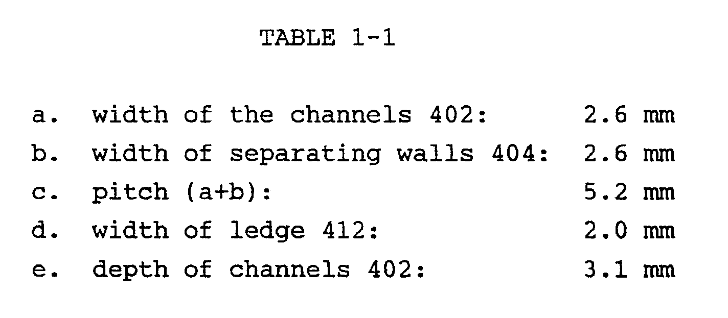
- the pitch of the base channels 402 i.e the distance between adjacent channels
- a ledge 412 around the perimeter of the base channels serves as a platform to support the interposer and distribution channel cover.
- FIG. 4B An isometric view of the base plate is illustrated in FIG. 4B.
- the base plate 400 has a rectangular opening of sufficient depth to support the interposer (which rests on the ledge 412) and the distribution plate (which fits snugly against the interposer).
- FIGs. 4A, 4B there are 15 channels. Exemplary measurements for the embodiment of FIGs. 4A, 4B are listed in table 1-1 below.
- the interposer plate 500 comprises a thin Copper sheet (approximately 0.5mm) into which a series of holes 502 and rectangular openings 504 have been machined.
- the holes 502 act as nozzles, increasing the velocity of the water as it travels through.
- the hole diameter, geometry, and density can be varied depending on the performance desired.
- An exemplary hole would be circular and have a diameter of 0.7mm.
- the holes are located so that they are centered above the base channels which would be situated below when the interposer plate is mounted to the base plate.
- the long, slender rectangular openings 504 which lie between rows of holes are perpendicularly located above a base channel situated below.
- the rectangular openings enable water which has entered the base channels to exit through the base plate to the outlet manifold chamber.
- small holes or other openings could be used in place of the rectangular openings 504.
- An exemplary size for the rectangular openings is 2.47mm by 75.8 mm.
- the two large rectangular openings 506, 508 cooperate with similar openings in the base and distributions plates to form the manifold chambers in the assembled cold plate 700 (FIG. 7).
- the distribution/cover plate 600 comprises a block of Copper into which a series of channels has been machined. Two sets of channels are machined into the plate; a set of inlet channels 602 and a set of outlet channels 604.
- the inlet and outlet channels are interleaved and independent of each other (i.e. they do not connect to each other on the distribution plate).
- the inlet channels (10 of them in the embodiment of FIGs. 6A-B) connect to a rectangular inlet manifold opening 606 which cooperates with similar openings 406, 506 in the base and interposer plates to form the inlet manifold chamber 702 in the assembled cold plate 700 (FIG. 7).
- the outlet channels (11 of them in the embodiment of FIGs.
- inlet and/or outlet channels can vary such that the channel depth is greatest adjacent to the manifold chamber and shallowest at the channel termination point, thereby providing constant coolant velocity along the length of the channels.
- the inlet channels are laid out such that when the cover is placed on top of the interposer, the inlet channels will be centered over the interposer nozzle holes. Likewise, the outlet channels will be centered over the rectangular outlet openings on the interposer.
- the pitch and number of inlet and outlet openings can be varied depending on the performance desired.
- the inlet and outlet manifold chambers include tapped holes 610, 612 for fittings.
- the width of the inlet/outlet channels and the width of the walls separating the inlet and outlet channels are preferably the same as width of the base plate channels 402 and separating walls 404, respectively. Given the examplary measurements of TABLE 1-1, a preferable depth of the inlet/outlet channels is 5.4mm.
- the inlet channels can be machined from the opposite face of the distribution plate and the interposer plate nozzles can be incorporated into the distribution plate by forming nozzle holes in the inlet channels 602.
- the rectangular manifold openings 606, 608 cooperate with similar openings in the base plate 400.
- a cover plate seals the inlet channels from the external environment and the coolant flows through the nozzle holes in the distribution plate and impinges on the bottom of the channels in the base plate 400.
- the interposer plate 500 is not required in the assembled cold plate.
- the coolant flow scheme in the module of FIG. 7 will now be explained by reference to FIGS. 4A-7.
- the coolant (represented by arrows in FIG. 7) enters the inlet 706 and charges the inlet manifold chamber 702.
- the coolant flows through the inlet channels 602 and is forced down through the nozzles 502 of the interposer 500.
- the coolant then impinges at the bottom of the base plate 400. After impinging at the bottom of the base plate, a portion of the coolant fluid turns outwardly (to the right in FIG. 4A) and the remaining portion turns inwardly (to the left in FIG. 4A) in the base channels 402 to become parallel with the base channel walls 404.
- the fluid continues along the base channels until it collides with coolant originating from adjacent nozzles.
- the combined and mixed coolant then turns upward and passes through the rectangular openings 504 (FIG. 5) in the interposer 500 and reaches the outlet channels 604 in the distribution/cover plate 600.
- the coolant flow continues through the outlet channels 604 and charges the outlet manifold chamber 704. The coolant then exhausts through the outlet 708.
- FIG. 11 illustrates an embodiment of the present cold plate having a manifold 1102 with multiple fittings 1104. The embodiment of FIG. 11 reduces the pressure drop penalty (as compared with a single fitting manifold) since much of the pressure drop is across the fittings.
- a manifold 1202 having a single large fitting i.e. the opening is a large as the manifold chamber
- FIG. 12 can be utilized as illustrated in FIG. 12.
- the cross hatch cold plate of FIG. 7 is assembled using a brazing process.
- the interposer is placed into the base; braze filler metal is added followed by the distribution/cover piece and addition braze filler.
- the entire assembly is then heated to brazing temperatures.
- FIGs. 13A and 13B illustrate an alternative, albeit less preferable, embodiment of a base and interposer plate using bosses for internal attachment.
- the interposer plate 1302 is placed over the base plate 1304.
- the assembled cold plate is then attached to a semiconductor cooling module by way of threaded screw holes 1306.
- the interposer plate can be modified to adjust and optimize the performance of the cold plate.
- the optimum impingement distance between the interposer and the floor of the base plate channels is 3.1mm.
- One way of achieving this optimum would be to use standard circular holes in the interposer plate and a channel height of 3.1mm in the distribution plate.
- increasing the height of the channels in the distribution plate can also add to performance by creating an extended cooling surface.
- the interposer plate can be provided with nozzles that extend into the distribution plate channels.
- the interposer plate nozzles could extend 4.9mm into the channels thus achieving the optimum 3.1mm impingement distance while at the same time providing an extended cooling surface on the distribution plate.
- filler materials such as strip fins, pellets or screens
- FIGs. 8 and 9 Another embodiment cross hatch flow distribution as applied to an integrated circuit cooling module 900 is illustrated in FIGs. 8 and 9.
- the cooling module of FIG. 9 comprises a body portion 800 and a distribution portion 802 which is preferably attached to the body by brazing.
- the cooling fluid is forced, under pressure, to flow through an extended nozzle interposer plate 906 ultimately imposing into a spherical cavity 902 within a cooling plug 903.
- Extended tubes (or nozzles) 901 in the interposer plate 906 have openings directly over the cooling plugs 903.
- the cooling plugs 903 are attached to the cooling device by means of a compliant membrane 904a. This enables single plugs to conform to chip height and tilt variability across an entire module.
- an outer frame 905 is attached to the cooling devices by means of an another compliant membrane 904b, of the same type used to attach the cooling plugs 903.
- This outer membrane 904b provides for module global compliance in the z direction.
- the compliant membranes provide for a compliant integrated circuit chip interface without the need for pistons and springs.
- the cooling fluid enters the inlet reservoir 806 (FIG. 8) through an inlet fitting or fittings 807. From the inlet manifold chamber 806, the fluid flows through a plurality of individual inlet channels 808. From the inlet channels, the fluid travels down the extended tubes 901 (FIG. 9) and impinges into the spherical cavities 902 within the cooling plugs 903. The geometry of the cavities 902 is such that the fluid is forced up and away from the plug once it impinges on the cavity base.
- the fluid exits through openings 809 in the interposer 900 which lie between the extended tube nozzles 901. The fluid travels through the openings 809 an enters the outlet channel 810 (FIG. 8).
- the fluid in the outlet channels then flows into the outlet manifold chamber 811 and finally exits the module through an outlet fitting or fittings 812.
- the inlet and outlet channels are separated to assist in uniform or customized flow distribution (i.e. channel pitch, size, and high can vary to control flow rate as dictated by device power).
- FIG. 10 depicts a module having a single large supply manifold 1002.
- This manifold structure supplies the extended tube nozzles with equal flow.
- the fluid exits by means of outlet ports 1004 located around the perimeter of the module.
- the base, interposer and distribution plates could also be made from a good heat conducting material other than copper and the plates and openings could be formed by casting or stamping.
Abstract
Description
- This invention relates to cross-hatch flow distribution for liquid cooling of semiconductor modules.
- Cooling of integrated circuit chips in large computers is often accomplished placing the chips in a number of liquid cooled modules. FIG. 1 shows a cross-sectional view of a prior art
thermal conduction module 10 for providing cooling of the integratedcircuit chips 12 contained therein. As is well known, the power consumed in the circuits within thechips 12 generates heat which must be removed. Thechips 12 may have different power requirements and different ranges of operating temperatures. Thus, in order to obtain reliable operation of the integrated circuits, the cooling must be of such character as to maintain the temperature of each chip within its required operating range. - The
chips 12 are mounted (by way of solder balls 28) on one side of asubstrate 14, generally made of ceramic, which haspins 16 extending from the other side thereof. These connectingpins 16 provide for the plugging of the module into a board (not shown) which may carry auxiliary circuits, etc. A housing orcap 18 is attached to thesubstrate 14 by means of aflange 20 which extends from the periphery of thesubstrate 14 to thecap 18. Thecap 18 is made of a good heat conductive material such as copper or aluminum. The cap has smallcylindrical openings 22 located therein, which are arranged in a matrix directly adjacent to the exposed surface of eachchip 12. - Each of the
openings 22 receives a spring loadedpin piston 24. Eachpiston 24 has asquare header 26 which contacts the chip surface. Heat generated by thechips 12 is carried away by thepistons 24 to thecap 18. Acold plate 30, attached to or designed as an integral part of thecap 18, transfers the heat to a stream of coolant (for example chilled water) which flows from aninlet 32 to anoutlet 34. The coolant carries the heat away from the thermalconduction module assembly 10. - As the power consumption of integrated chips has increased, the amount of heat which needs to removed from the chips and the thermal conduction module has increased as well. Since the ability of the thermal conduction module to remove heat from the chips is dependant on the ability of the cold plate to remove heat from the pistons and the TCM cap, a great deal of design effort has been put into developing an efficient cold plate design.
- FIG. 2 shows a top-cutaway view of a prior art
cold plate 200 having a serpentinecoolant flow path 202 between aninlet 203 and anoutlet 204. A number ofbolt holes 205 are provided for attaching the cold plate to the cap of a thermal conduction module. One limitation of the cold plate of FIG. 2 is that the serpentine coolant flow path is generally serial. Thus, a single stream of coolant carries away heat from the chips as it passes over the pistons on its way from theinlet 203 to theoutlet 204. Given such a serial flow path, in order to properly cool chips having higher power dissipations the rate of water flow must substantially be increased. - Increasing the flow rate to accommodate chips with high power dissipations can prove to be a difficult and costly exercise. In order to accomplish an increase of flow rate by a factor of X, the pressure drop between the inlet and the outlet of the TCM must be increased by X squared. Increases in pressure can be costly in several respects. For example, increasing coolant pressure typically requires larger and more expensive compression/cooling units. Further, suitable fittings and coolant supply tubing (typically more expensive) must be provided to accommodate the higher pressures.
- Another problem with serial flow paths is that as the length of the path increases the required pressure drop must also be increased in proportional relationship to maintain a given flow rate. Thus, if the substrate to be cooled becomes larger, or the number of rows of integrated circuits on a given sized substrate increases, the longer flow path will cause a proportional increase in the required pressure drop.
- FIG. 3 shows an example of another prior art
cold plate 300 that uses fins for improved heat transfer. Fourfins 302 extend from two opposite walls of the cold plate to form a sinuous path for water flow. Each parallel segment of the path is relatively wide and is further divided into four parallel channels by a three by three parallel line ofshort fins 304. The gaps between the short fins increase the turbulence in the water flow. The parallel channels provide increased fin area with lower flow resistance. While the embodiment of FIG. 3 is an improvement over that of FIG. 2, the coolant is still forced to flow along an essentially serial path over the pins of the TCM. Further, as the number of fins is increased the pressure drop required to maintain sufficient cooling is increased as well. - The invention as claimed is intended to remedy these drawbacks. It is therefore an object of the invention to enhance removing of heat from integrated circuits having high power dissipations.
- In a first embodiment of the invention there is provided, a cold plate having a cross-hatch flow distribution scheme comprising two sets of nonplaner channels which are disposed angularly to each other. The first set of channels is formed on a base plate while the second, set is formed on a distribution plate. In the preferred embodiment, the base and distribution plates are separated by an interposer to improve and customize cold plate performance.
- In a second embodiment of the invention, there is provided a heat removal apparatus, including a body having a top portion, a central portion and a bottom portion. The top portion includes a plurality of coolant inlet channels interleaved with plurality of coolant outlet channels. The bottom portion includes a plurality of cooling plugs connected to the body by way of a plurality of compliant members. The central portion includes a plurality of nozzles which extend from the inlet channels, into the cooling plugs, so as to cause a liquid coolant in the inlet channels to impinge onto the plugs.
- This is accomplished by using a liquid coolant flowing at an inlet to outlet pressure drop superior to that by the prior art. Further provided is an indirect impingement cooling scheme which removes heat more efficiently than those found in the prior art.
- For a better understanding of the present invention, together with further objects and advantages, preferred embodiments of the invention are described in the following with reference to the accompanying drawings, in which:
- FIG. 1
- is a cutaway view of a prior art thermal conduction module;
- FIG. 2
- is a top cutaway view of a prior art cold plate having a serpentine flow path;
- FIG. 3
- is a top cutaway view of a prior art cold plate having fins and a serpentine flow path;
- FIG. 4A
- is a top view of a base plate according to a preferred embodiment of the present invention;
- FIG. 4B
- is an isometric view of the base plate of FIG. 4A;
- FIG. 5
- is a top view of an interposer plate according to a preferred embodiment of the present invention;
- FIG. 6A
- is a top cutaway view of a distribution plate according to a preferred embodiment of the present invention;
- FIG. 6B
- is a side cutaway view of the distribution plate of FIG. 6A taken along
line 6B; - FIG. 7
- is a side cutaway view of an assembled cold plate incorporating cross hatch flow distribution, showing the base, interposer and distribution plates of FIGs. 4A-B, 5 and 6A-B;
- FIG. 8
- is a top cutaway view of the distribution portion of the integrated circuit cooling module of FIG. 9;
- FIG. 9
- is a side cutaway view of an integrated circuit cooling module using cross hatch flow distribution;
- FIG. 10
- illustrates an embodiment of the integrated circuit cooling module of FIG. 9, having a single large manifold;
- FIG. 11
- illustrates a manifold having multiple fittings;
- FIG. 12
- illustrates a manifold having a single large opening as a fitting; and
- FIGs. 13A
- and 13B illustrate, respectively, an embodiment of a base and interposer plate using internal bosses for separable cold plate attachment to a integrated circuit cooling module.
- The cross-hatch flow distribution scheme comprises two sets of channels which run perpendicular to each other. A first set of channels is formed on a base plate (FIGs. 4A-B) while a second, perpendicular set is formed on a distribution plate (FIGs. 6A-B). The base and distribution plates can be separated by an interposer (FIG. 5) to customize and improve performance.
- FIG. 7 is a side cutaway view of an assembled cold plate incorporating cross hatch flow distribution, showing the
base 400,interposer 500 anddistribution 600 plates of FIGs. 4A-B, 5 and 6A-B. As illustrated in FIG. 7, rectangular openings in the base, interposer and distribution plates cooperate to form aninlet manifold chamber 702 and and outletmanifold chamber 704. Aninlet 706 is connected to supply coolant to theinlet manifold chamber 702 while anoutlet 708 is connected to carry away coolant from the outletmanifold chamber 704. - The
distribution plate 600 preferably comprises a block of copper into which a series of interleaved parallel channels (shown in FIG, 6A, 6B) have been machined. In the orientation illustrated in FIG, 7, the distribution plate channels would run in the directions indicated by arrows BB. - The
base plate 400 also preferably comprises a block of copper into which a series ofparallel channels 402 have been machined. Thechannels 402 in thebase plate 400 are oriented perpendicularly to the channels in thedistribution plate 600. - In the embodiment of FIG. 7, the
interposer 500 is sandwiched in between the base anddistribution plates interposer 500 preferably comprises a thin copper sheet into which a series of holes and rectangular openings have been machined (respectively 502, 504 of FIG. 5). The holes are arranged into lines which are interleaved with the openings. The lines of holes and the openings are parallel to each other and run in the direction of arrows BE in the orientation of the cold plate illustrated in FIG. 7. In the assembledcold plate 700 the lines of holes run perpendicularly to thebase plate channels 402. Eachhole 502 in a given line is centered above one of thebase plate channels 402. - Turning now to FIG. 4A, the base plate 400 (FIG. 4A) comprises a solid block of copper into which
channels 402 have been machined. Each channel is separated from its adjacent channel by asolid wall 404. The channel depth can be varied depending upon the performance desired. At opposite ends of the base plate are twolarge channels manifold chambers holes 410 around the perimeter of the base plate serve as locators for mounting screws. The pitch of the base channels 402 (i.e the distance between adjacent channels) as well as the number/width of channels can be varied depending on the performance desired. Aledge 412 around the perimeter of the base channels serves as a platform to support the interposer and distribution channel cover. - An isometric view of the base plate is illustrated in FIG. 4B. As illustrated in FIG. 4B, the
base plate 400 has a rectangular opening of sufficient depth to support the interposer (which rests on the ledge 412) and the distribution plate (which fits snugly against the interposer). - In the embodiment of FIGs. 4A, 4B there are 15 channels. Exemplary measurements for the embodiment of FIGs. 4A, 4B are listed in table 1-1 below.
- Turning now to FIG. 5, the
interposer plate 500 comprises a thin Copper sheet (approximately 0.5mm) into which a series ofholes 502 andrectangular openings 504 have been machined. Theholes 502 act as nozzles, increasing the velocity of the water as it travels through. The hole diameter, geometry, and density can be varied depending on the performance desired. An exemplary hole would be circular and have a diameter of 0.7mm. The holes are located so that they are centered above the base channels which would be situated below when the interposer plate is mounted to the base plate. - The long, slender
rectangular openings 504 which lie between rows of holes are perpendicularly located above a base channel situated below. The rectangular openings enable water which has entered the base channels to exit through the base plate to the outlet manifold chamber. Alternatively, small holes or other openings could be used in place of therectangular openings 504. An exemplary size for the rectangular openings is 2.47mm by 75.8 mm. The two largerectangular openings - Turning now to FIG. 6A, the distribution/
cover plate 600 comprises a block of Copper into which a series of channels has been machined. Two sets of channels are machined into the plate; a set ofinlet channels 602 and a set ofoutlet channels 604. The inlet and outlet channels are interleaved and independent of each other (i.e. they do not connect to each other on the distribution plate). The inlet channels (10 of them in the embodiment of FIGs. 6A-B) connect to a rectangularinlet manifold opening 606 which cooperates withsimilar openings inlet manifold chamber 702 in the assembled cold plate 700 (FIG. 7). The outlet channels (11 of them in the embodiment of FIGs. 6A-B) connect to an rectangular outletmanifold opening 608 which cooperates withsimilar openings manifold chamber 704 in the assembled cold plate 700 (FIG. 7). The depth of the inlet and/or outlet channels can vary such that the channel depth is greatest adjacent to the manifold chamber and shallowest at the channel termination point, thereby providing constant coolant velocity along the length of the channels. - The inlet channels are laid out such that when the cover is placed on top of the interposer, the inlet channels will be centered over the interposer nozzle holes. Likewise, the outlet channels will be centered over the rectangular outlet openings on the interposer. The pitch and number of inlet and outlet openings can be varied depending on the performance desired. The inlet and outlet manifold chambers include tapped
holes base plate channels 402 and separatingwalls 404, respectively. Given the examplary measurements of TABLE 1-1, a preferable depth of the inlet/outlet channels is 5.4mm. - As an alternative to the embodiment of FIG. 6A, the inlet channels can be machined from the opposite face of the distribution plate and the interposer plate nozzles can be incorporated into the distribution plate by forming nozzle holes in the
inlet channels 602. In this alternative embodiment, therectangular manifold openings base plate 400. A cover plate seals the inlet channels from the external environment and the coolant flows through the nozzle holes in the distribution plate and impinges on the bottom of the channels in thebase plate 400. When such an embodiment of the distribution plate is used, theinterposer plate 500 is not required in the assembled cold plate. - The coolant flow scheme in the module of FIG. 7 will now be explained by reference to FIGS. 4A-7. The coolant (represented by arrows in FIG. 7) enters the
inlet 706 and charges theinlet manifold chamber 702. The coolant flows through theinlet channels 602 and is forced down through thenozzles 502 of theinterposer 500. The coolant then impinges at the bottom of thebase plate 400. After impinging at the bottom of the base plate, a portion of the coolant fluid turns outwardly (to the right in FIG. 4A) and the remaining portion turns inwardly (to the left in FIG. 4A) in thebase channels 402 to become parallel with thebase channel walls 404. The fluid continues along the base channels until it collides with coolant originating from adjacent nozzles. The combined and mixed coolant then turns upward and passes through the rectangular openings 504 (FIG. 5) in theinterposer 500 and reaches theoutlet channels 604 in the distribution/cover plate 600. The coolant flow continues through theoutlet channels 604 and charges the outletmanifold chamber 704. The coolant then exhausts through theoutlet 708. - Although conventional manifolds having single inlet an outlet fittings can be used in conjunction with the cold plate of FIG. 7, the inlet and outlet manifolds can be adapted to have multiple fittings. FIG. 11 illustrates an embodiment of the present cold plate having a manifold 1102 with
multiple fittings 1104. The embodiment of FIG. 11 reduces the pressure drop penalty (as compared with a single fitting manifold) since much of the pressure drop is across the fittings. As a further alternative embodiment, a manifold 1202 having a single large fitting (i.e. the opening is a large as the manifold chamber) can be utilized as illustrated in FIG. 12. - The cross hatch cold plate of FIG. 7 is assembled using a brazing process. The interposer is placed into the base; braze filler metal is added followed by the distribution/cover piece and addition braze filler. The entire assembly is then heated to brazing temperatures.
- FIGs. 13A and 13B illustrate an alternative, albeit less preferable, embodiment of a base and interposer plate using bosses for internal attachment. In the embodiment of FIGs. 13A, 13B the
interposer plate 1302 is placed over thebase plate 1304. The assembled cold plate is then attached to a semiconductor cooling module by way of threaded screw holes 1306. - Advantageously, the interposer plate can be modified to adjust and optimize the performance of the cold plate. For example, in the cold plate of FIG 7, the optimum impingement distance between the interposer and the floor of the base plate channels (given the exemplary dimensions listed above) is 3.1mm. One way of achieving this optimum would be to use standard circular holes in the interposer plate and a channel height of 3.1mm in the distribution plate. However, increasing the height of the channels in the distribution plate can also add to performance by creating an extended cooling surface.
- In order to provide for optimization of impingement height and desired channel depth, the interposer plate can be provided with nozzles that extend into the distribution plate channels. Thus, were the distribution plate channels extended to a depth of 8.0mm, the interposer plate nozzles could extend 4.9mm into the channels thus achieving the optimum 3.1mm impingement distance while at the same time providing an extended cooling surface on the distribution plate.
- As a further embodiment, filler materials (such as strip fins, pellets or screens) can be added to the distribution and/or base plate channels to enhance cooling.
- Another embodiment cross hatch flow distribution as applied to an integrated
circuit cooling module 900 is illustrated in FIGs. 8 and 9. The cooling module of FIG. 9 comprises abody portion 800 and adistribution portion 802 which is preferably attached to the body by brazing. In the embodiment of FIGs. 8 and 9, the cooling fluid is forced, under pressure, to flow through an extendednozzle interposer plate 906 ultimately imposing into aspherical cavity 902 within acooling plug 903. Extended tubes (or nozzles) 901 in theinterposer plate 906 have openings directly over the cooling plugs 903. The cooling plugs 903 are attached to the cooling device by means of acompliant membrane 904a. This enables single plugs to conform to chip height and tilt variability across an entire module. In addition, anouter frame 905 is attached to the cooling devices by means of an anothercompliant membrane 904b, of the same type used to attach the cooling plugs 903. Thisouter membrane 904b provides for module global compliance in the z direction. Advantageously, the compliant membranes provide for a compliant integrated circuit chip interface without the need for pistons and springs. - The fluid flow scheme in the module of FIG. 9 will now be explained by reference to FIGs. 8 and 9. The cooling fluid (not shown) enters the inlet reservoir 806 (FIG. 8) through an inlet fitting or
fittings 807. From theinlet manifold chamber 806, the fluid flows through a plurality ofindividual inlet channels 808. From the inlet channels, the fluid travels down the extended tubes 901 (FIG. 9) and impinges into thespherical cavities 902 within the cooling plugs 903. The geometry of thecavities 902 is such that the fluid is forced up and away from the plug once it impinges on the cavity base. The fluid exits throughopenings 809 in theinterposer 900 which lie between theextended tube nozzles 901. The fluid travels through theopenings 809 an enters the outlet channel 810 (FIG. 8). The fluid in the outlet channels then flows into the outletmanifold chamber 811 and finally exits the module through an outlet fitting orfittings 812. - The inlet and outlet channels are separated to assist in uniform or customized flow distribution (i.e. channel pitch, size, and high can vary to control flow rate as dictated by device power).
- In another embodiment, FIG. 10 depicts a module having a single
large supply manifold 1002. This manifold structure supplies the extended tube nozzles with equal flow. The fluid exits by means ofoutlet ports 1004 located around the perimeter of the module. - The base, interposer and distribution plates could also be made from a good heat conducting material other than copper and the plates and openings could be formed by casting or stamping.
Claims (17)
- A heat removal apparatus comprising:
a first plate (600) having a first plurality of inlet channels (602) and a second plurality of outlet channels (604) formed therein and disposed so as to be interleaved with said inlet channels;
a second plate (400) having a third plurality of cooling channels (402) formed therein, said second plate being disposed in communication with said first plate to cause said cooling channels to be angular to and nonplaner with both said inlet channels and said outlet channels;
wherein said first and second plates cooperate to form a flow path from said inlet channels through said cooling channels to said outlet channels. - The heat removal apparatus of Claim 1 wherein said third plurality of cooling channels are disposed so as to be perpendicular with both said inlet channels and said outlet channels.
- The heat removal apparatus of Claim 1 or 2 wherein said first plate further comprises a plurality of nozzles (502) formed in said inlet channels.
- The heat removal apparatus of Claim 1, further comprising:
a third plate (500) having a plurality of nozzles (502) formed therein, said third plate being disposed between said first plate and said second plate. - The heat removal apparatus of claim 4, wherein said second plate comprises a plurality of bosses extending therefrom and wherein said third plate has a plurality of openings formed therein disposed to receive said bosses when said third plate is mounted to said second plate.
- The heat removal apparatus of claims 4 or 5, wherein each of said first, second and third plates have a manifold openings formed therein which cooperate to form an inlet manifold chamber and an outlet manifold chamber.
- The heat removal apparatus of any one of the preceding claims 4 to 6 wherein said nozzles extend into said cooling channels.
- The heat removal apparatus of any one of the preceding claims 4 to 7 wherein said nozzles are arranged into a plurality of parallel lines and wherein said parallel lines are disposed perpendicularly to said cooling channels.
- The heat removal apparatus of any one of the preceding claims 4 to 7, wherein said third plate further comprises a plurality of elongated openings formed therein, interleaved with said lines.
- The heat removal apparatus of any one of the preceding claims, further comprising an inlet manifold chamber (702) coupled to said inlet channels and an outlet manifold chamber (704) coupled to said outlet channels.
- The heat removal apparatus of Claim 10, further comprising a plurality of inlet fittings connected to said inlet manifold chamber.
- The heat removal apparatus of Claim 10 or 11 wherein said inlet channels are of a depth that decreases with distance from said inlet manifold chamber.
- The heat removal apparatus of Claim 10, further comprising an inlet fitting connected to said inlet manifold chamber an outlet fitting connected to said outlet manifold chamber.
- The heat removal apparatus of Claim 13, wherein said inlet fitting is of substantially the same perimeter as said inlet manifold chamber and said outlet fitting is of substantially the same perimeter as said outlet manifold chamber.
- A heat removal apparatus, comprising:
a body (800) having a top portion, a central portion and a bottom portion,
said top portion (802) comprising a plurality of coolant inlet channels (808) and a plurality of coolant outlet channels interleaved with said coolant inlet channels;
said bottom portion comprising a plurality of cooling plugs (903), and a plurality of first compliant members connected said cooling plugs to said body;
said central portion (906) comprising a plurality of nozzles (901) connected to said inlet channels, and extending into said cooling plugs. - The heat removal apparatus of Claim 15, further comprising a second compliant member disposed between said top portion and said bottom portion.
- The heat removal apparatus of Claim 15 or 16, wherein said cooling plugs each have a spherical cavity (902) formed therein and wherein said spherical cavity is disposed so as to receive coolant from at least one of said nozzles.
Applications Claiming Priority (2)
| Application Number | Priority Date | Filing Date | Title |
|---|---|---|---|
| US07/496,838 US5016090A (en) | 1990-03-21 | 1990-03-21 | Cross-hatch flow distribution and applications thereof |
| US496838 | 1990-03-21 |
Publications (2)
| Publication Number | Publication Date |
|---|---|
| EP0447835A2 true EP0447835A2 (en) | 1991-09-25 |
| EP0447835A3 EP0447835A3 (en) | 1991-11-13 |
Family
ID=23974372
Family Applications (1)
| Application Number | Title | Priority Date | Filing Date |
|---|---|---|---|
| EP19910102685 Withdrawn EP0447835A3 (en) | 1990-03-21 | 1991-02-23 | Heat removal apparatus for liquid cooled semiconductor modules |
Country Status (3)
| Country | Link |
|---|---|
| US (1) | US5016090A (en) |
| EP (1) | EP0447835A3 (en) |
| JP (1) | JPH0722190B2 (en) |
Cited By (8)
| Publication number | Priority date | Publication date | Assignee | Title |
|---|---|---|---|---|
| EP0538465A1 (en) * | 1991-04-09 | 1993-04-28 | United States Department Of Energy | Thin planer package for cooling an array of edge-emitting laser diodes |
| DE4217289A1 (en) * | 1992-05-25 | 1993-12-16 | Mannesmann Ag | Fluid-cooled power transistor device, e.g. IGBT, MOSFET or BIMOS for controlling machine |
| DE4322665A1 (en) * | 1992-07-16 | 1994-01-20 | Fuji Electric Co Ltd | Cooling appts. for power semiconductor device e.g. in motor vehicle - has coolant passage contg. cooling plates which are alternately stacked with semiconductor elements and form coolant circuit |
| GB2313960A (en) * | 1996-06-08 | 1997-12-10 | Marconi Gec Ltd | Heat sink including a cooling pipe having a planar section |
| US5983997A (en) * | 1996-10-17 | 1999-11-16 | Brazonics, Inc. | Cold plate having uniform pressure drop and uniform flow rate |
| DE19827096A1 (en) * | 1998-06-18 | 1999-12-23 | Behr Gmbh & Co | Heat transfer device e.g. for cooling electronic module or for automobile heat exchanger |
| US6317326B1 (en) * | 2000-09-14 | 2001-11-13 | Sun Microsystems, Inc. | Integrated circuit device package and heat dissipation device |
| US8066057B2 (en) | 2003-10-27 | 2011-11-29 | Danfoss Silicon Power Gmbh | Flow distributing unit and cooling unit |
Families Citing this family (110)
| Publication number | Priority date | Publication date | Assignee | Title |
|---|---|---|---|---|
| US5265670A (en) * | 1990-04-27 | 1993-11-30 | International Business Machines Corporation | Convection transfer system |
| US5170319A (en) * | 1990-06-04 | 1992-12-08 | International Business Machines Corporation | Enhanced multichip module cooling with thermally optimized pistons and closely coupled convective cooling channels |
| JP2995590B2 (en) * | 1991-06-26 | 1999-12-27 | 株式会社日立製作所 | Semiconductor cooling device |
| US5239200A (en) * | 1991-08-21 | 1993-08-24 | International Business Machines Corporation | Apparatus for cooling integrated circuit chips |
| JPH0824222B2 (en) * | 1992-04-10 | 1996-03-06 | インターナショナル・ビジネス・マシーンズ・コーポレイション | Cooling device with air-mixer cooling plate |
| FR2701554B1 (en) * | 1993-02-12 | 1995-05-12 | Transcal | Heat exchanger for electronic components and electro-technical equipment. |
| DE19514548C1 (en) * | 1995-04-20 | 1996-10-02 | Daimler Benz Ag | Method of manufacturing a micro cooler |
| US5835345A (en) * | 1996-10-02 | 1998-11-10 | Sdl, Inc. | Cooler for removing heat from a heated region |
| EP0905353B1 (en) * | 1997-09-30 | 2003-01-15 | ALSTOM (Switzerland) Ltd | Impingement arrangement for a convective cooling or heating process |
| US6349760B1 (en) * | 1999-10-22 | 2002-02-26 | Intel Corporation | Method and apparatus for improving the thermal performance of heat sinks |
| US6257320B1 (en) * | 2000-03-28 | 2001-07-10 | Alec Wargo | Heat sink device for power semiconductors |
| GB0011916D0 (en) * | 2000-05-17 | 2000-07-05 | Cambridge Consultants | Printing |
| JP3857060B2 (en) * | 2001-02-09 | 2006-12-13 | 株式会社東芝 | Heating element cooling device |
| US6519151B2 (en) * | 2001-06-27 | 2003-02-11 | International Business Machines Corporation | Conic-sectioned plate and jet nozzle assembly for use in cooling an electronic module, and methods of fabrication thereof |
| KR100456342B1 (en) * | 2002-02-08 | 2004-11-12 | 쿨랜스코리아 주식회사 | A water cooling type cooling block for semiconductor chip |
| US6988534B2 (en) | 2002-11-01 | 2006-01-24 | Cooligy, Inc. | Method and apparatus for flexible fluid delivery for cooling desired hot spots in a heat producing device |
| US6881039B2 (en) * | 2002-09-23 | 2005-04-19 | Cooligy, Inc. | Micro-fabricated electrokinetic pump |
| US20040076408A1 (en) * | 2002-10-22 | 2004-04-22 | Cooligy Inc. | Method and apparatus for removeably coupling a heat rejection device with a heat producing device |
| US6994151B2 (en) | 2002-10-22 | 2006-02-07 | Cooligy, Inc. | Vapor escape microchannel heat exchanger |
| US7836597B2 (en) | 2002-11-01 | 2010-11-23 | Cooligy Inc. | Method of fabricating high surface to volume ratio structures and their integration in microheat exchangers for liquid cooling system |
| WO2004042306A2 (en) * | 2002-11-01 | 2004-05-21 | Cooligy, Inc. | Method and apparatus for achieving temperature uniformity and hot spot cooling in a heat producing device |
| US8464781B2 (en) * | 2002-11-01 | 2013-06-18 | Cooligy Inc. | Cooling systems incorporating heat exchangers and thermoelectric layers |
| DE10393588T5 (en) * | 2002-11-01 | 2006-02-23 | Cooligy, Inc., Mountain View | Optimal propagation system, apparatus and method for liquid cooled, microscale heat exchange |
| US20050211427A1 (en) * | 2002-11-01 | 2005-09-29 | Cooligy, Inc. | Method and apparatus for flexible fluid delivery for cooling desired hot spots in a heat producing device |
| US6986382B2 (en) * | 2002-11-01 | 2006-01-17 | Cooligy Inc. | Interwoven manifolds for pressure drop reduction in microchannel heat exchangers |
| US7156159B2 (en) * | 2003-03-17 | 2007-01-02 | Cooligy, Inc. | Multi-level microchannel heat exchangers |
| US7000684B2 (en) * | 2002-11-01 | 2006-02-21 | Cooligy, Inc. | Method and apparatus for efficient vertical fluid delivery for cooling a heat producing device |
| US20050211417A1 (en) * | 2002-11-01 | 2005-09-29 | Cooligy,Inc. | Interwoven manifolds for pressure drop reduction in microchannel heat exchangers |
| US6778393B2 (en) * | 2002-12-02 | 2004-08-17 | International Business Machines Corporation | Cooling device with multiple compliant elements |
| US7201012B2 (en) * | 2003-01-31 | 2007-04-10 | Cooligy, Inc. | Remedies to prevent cracking in a liquid system |
| US7044196B2 (en) * | 2003-01-31 | 2006-05-16 | Cooligy,Inc | Decoupled spring-loaded mounting apparatus and method of manufacturing thereof |
| US7293423B2 (en) * | 2004-06-04 | 2007-11-13 | Cooligy Inc. | Method and apparatus for controlling freezing nucleation and propagation |
| US20040182551A1 (en) * | 2003-03-17 | 2004-09-23 | Cooligy, Inc. | Boiling temperature design in pumped microchannel cooling loops |
| US7017654B2 (en) * | 2003-03-17 | 2006-03-28 | Cooligy, Inc. | Apparatus and method of forming channels in a heat-exchanging device |
| US7591302B1 (en) | 2003-07-23 | 2009-09-22 | Cooligy Inc. | Pump and fan control concepts in a cooling system |
| US6917099B2 (en) * | 2003-08-27 | 2005-07-12 | Hewlett-Packard Development Company, L.P. | Die carrier with fluid chamber |
| JP4014549B2 (en) * | 2003-09-18 | 2007-11-28 | 富士電機システムズ株式会社 | Heat sink and manufacturing method thereof |
| US20050128705A1 (en) * | 2003-12-16 | 2005-06-16 | International Business Machines Corporation | Composite cold plate assembly |
| US20050199372A1 (en) * | 2004-03-08 | 2005-09-15 | Frazer James T. | Cold plate and method of making the same |
| US7616444B2 (en) | 2004-06-04 | 2009-11-10 | Cooligy Inc. | Gimballed attachment for multiple heat exchangers |
| US7188662B2 (en) * | 2004-06-04 | 2007-03-13 | Cooligy, Inc. | Apparatus and method of efficient fluid delivery for cooling a heat producing device |
| US20060042785A1 (en) * | 2004-08-27 | 2006-03-02 | Cooligy, Inc. | Pumped fluid cooling system and method |
| CN100389371C (en) * | 2004-09-16 | 2008-05-21 | 中芯国际集成电路制造(上海)有限公司 | Device and method for voltage regulator with low stand-by current |
| US20060096738A1 (en) * | 2004-11-05 | 2006-05-11 | Aavid Thermalloy, Llc | Liquid cold plate heat exchanger |
| US7230334B2 (en) * | 2004-11-12 | 2007-06-12 | International Business Machines Corporation | Semiconductor integrated circuit chip packages having integrated microchannel cooling modules |
| US7353859B2 (en) * | 2004-11-24 | 2008-04-08 | General Electric Company | Heat sink with microchannel cooling for power devices |
| US7327024B2 (en) * | 2004-11-24 | 2008-02-05 | General Electric Company | Power module, and phase leg assembly |
| US7233494B2 (en) * | 2005-05-06 | 2007-06-19 | International Business Machines Corporation | Cooling apparatus, cooled electronic module and methods of fabrication thereof employing an integrated manifold and a plurality of thermally conductive fins |
| US7201217B2 (en) * | 2005-05-24 | 2007-04-10 | Raytheon Company | Cold plate assembly |
| US20070114010A1 (en) * | 2005-11-09 | 2007-05-24 | Girish Upadhya | Liquid cooling for backlit displays |
| US20070175621A1 (en) * | 2006-01-31 | 2007-08-02 | Cooligy, Inc. | Re-workable metallic TIM for efficient heat exchange |
| WO2007098078A2 (en) | 2006-02-16 | 2007-08-30 | Cooligy, Inc. | Liquid cooling loops for server applications |
| WO2007120530A2 (en) | 2006-03-30 | 2007-10-25 | Cooligy, Inc. | Integrated liquid to air conduction module |
| US20070227698A1 (en) * | 2006-03-30 | 2007-10-04 | Conway Bruce R | Integrated fluid pump and radiator reservoir |
| US7715194B2 (en) | 2006-04-11 | 2010-05-11 | Cooligy Inc. | Methodology of cooling multiple heat sources in a personal computer through the use of multiple fluid-based heat exchanging loops coupled via modular bus-type heat exchangers |
| US7545644B2 (en) * | 2006-05-16 | 2009-06-09 | Georgia Tech Research Corporation | Nano-patch thermal management devices, methods, & systems |
| JP4675283B2 (en) * | 2006-06-14 | 2011-04-20 | トヨタ自動車株式会社 | Heat sink and cooler |
| US20080006396A1 (en) * | 2006-06-30 | 2008-01-10 | Girish Upadhya | Multi-stage staggered radiator for high performance liquid cooling applications |
| US7450384B2 (en) * | 2006-07-06 | 2008-11-11 | Hybricon Corporation | Card cage with parallel flow paths having substantially similar lengths |
| JP2008027374A (en) * | 2006-07-25 | 2008-02-07 | Fujitsu Ltd | Heat receiver for liquid cooling unit, liquid cooling unit, and electronic device |
| JP5283836B2 (en) * | 2006-07-25 | 2013-09-04 | 富士通株式会社 | Heat receiver and liquid cooling unit for liquid cooling unit and electronic device |
| JP2008159619A (en) * | 2006-12-20 | 2008-07-10 | Shinko Electric Ind Co Ltd | Semiconductor device |
| WO2008137143A1 (en) * | 2007-05-02 | 2008-11-13 | Cooligy Inc. | Micro-tube/multi-port counter flow radiator design for electronic cooling applications |
| US7884468B2 (en) * | 2007-07-30 | 2011-02-08 | GM Global Technology Operations LLC | Cooling systems for power semiconductor devices |
| TW200924625A (en) * | 2007-08-07 | 2009-06-01 | Cooligy Inc | Deformable duct guides that accommodate electronic connection lines |
| US9453691B2 (en) | 2007-08-09 | 2016-09-27 | Coolit Systems, Inc. | Fluid heat exchange systems |
| US8746330B2 (en) * | 2007-08-09 | 2014-06-10 | Coolit Systems Inc. | Fluid heat exchanger configured to provide a split flow |
| US20090205809A1 (en) * | 2008-02-19 | 2009-08-20 | Man Zai Industrial Co., Ltd. | Liquid cooling device |
| US20090225514A1 (en) | 2008-03-10 | 2009-09-10 | Adrian Correa | Device and methodology for the removal of heat from an equipment rack by means of heat exchangers mounted to a door |
| US9297571B1 (en) | 2008-03-10 | 2016-03-29 | Liebert Corporation | Device and methodology for the removal of heat from an equipment rack by means of heat exchangers mounted to a door |
| US8302671B2 (en) * | 2008-04-29 | 2012-11-06 | Raytheon Company | Scaleable parallel flow micro-channel heat exchanger and method for manufacturing same |
| US8254422B2 (en) | 2008-08-05 | 2012-08-28 | Cooligy Inc. | Microheat exchanger for laser diode cooling |
| US8248809B2 (en) * | 2008-08-26 | 2012-08-21 | GM Global Technology Operations LLC | Inverter power module with distributed support for direct substrate cooling |
| US20110073292A1 (en) * | 2009-09-30 | 2011-03-31 | Madhav Datta | Fabrication of high surface area, high aspect ratio mini-channels and their application in liquid cooling systems |
| US8169779B2 (en) * | 2009-12-15 | 2012-05-01 | GM Global Technology Operations LLC | Power electronics substrate for direct substrate cooling |
| US9267742B2 (en) * | 2010-01-27 | 2016-02-23 | Applied Materials, Inc. | Apparatus for controlling the temperature uniformity of a substrate |
| US8305755B2 (en) * | 2010-03-04 | 2012-11-06 | Toyota Motor Engineering & Manufacturing North America, Inc. | Power modules, cooling devices and methods thereof |
| KR101209686B1 (en) * | 2010-12-03 | 2012-12-10 | 기아자동차주식회사 | Cooling device for electric parts of electric vehicle and hybridelectric vehicle |
| US10365667B2 (en) | 2011-08-11 | 2019-07-30 | Coolit Systems, Inc. | Flow-path controllers and related systems |
| US20130056176A1 (en) * | 2011-08-26 | 2013-03-07 | Mikros Manufacturing, Inc. | Heat Exchanger with Controlled Coefficient of Thermal Expansion |
| US9353999B2 (en) * | 2012-07-30 | 2016-05-31 | Toyota Motor Engineering & Manufacturing North America, Inc. | Cooling apparatuses and electronics modules having branching microchannels |
| US10364809B2 (en) | 2013-03-15 | 2019-07-30 | Coolit Systems, Inc. | Sensors, multiplexed communication techniques, and related systems |
| US9210831B2 (en) * | 2013-04-15 | 2015-12-08 | International Business Machines Corporation | Separable and integrated heat sinks facilitating cooling multi-compnent electronic assembly |
| WO2015178064A1 (en) * | 2014-05-20 | 2015-11-26 | 富士電機株式会社 | Semiconductor module cooler and method for manufacturing same |
| JP2016018953A (en) * | 2014-07-10 | 2016-02-01 | 株式会社フジクラ | Cold plate |
| US10415903B2 (en) * | 2014-10-15 | 2019-09-17 | Hamilton Sundstrand Corporation | Prevention of cooling flow blockage |
| JP6394267B2 (en) * | 2014-10-15 | 2018-09-26 | 富士通株式会社 | Cooling device and electronic equipment |
| US10415597B2 (en) | 2014-10-27 | 2019-09-17 | Coolit Systems, Inc. | Fluid heat exchange systems |
| US9445526B2 (en) * | 2014-12-22 | 2016-09-13 | Toyota Motor Engineering & Manufacturing North America, Inc. | Modular jet impingement assemblies with passive and active flow control for electronics cooling |
| JP6831120B2 (en) * | 2016-01-21 | 2021-02-17 | エタリム インコーポレイテッド | Equipment and systems for heat exchange with fluids |
| JP2017163065A (en) * | 2016-03-11 | 2017-09-14 | 富士通株式会社 | Electronic apparatus |
| DE102016216245A1 (en) * | 2016-08-30 | 2018-03-01 | Zf Friedrichshafen Ag | Arrangement for fluid temperature control |
| US11452243B2 (en) | 2017-10-12 | 2022-09-20 | Coolit Systems, Inc. | Cooling system, controllers and methods |
| US11557521B2 (en) | 2017-10-26 | 2023-01-17 | Mitsubishi Electric Corporation | Heat sink and circuit device |
| DE102018203362A1 (en) * | 2018-03-07 | 2019-09-12 | Robert Bosch Gmbh | Cooling device for cooling a power device |
| CN111406314B (en) * | 2018-06-27 | 2023-09-22 | 富士电机株式会社 | Cooling device, semiconductor module, and vehicle |
| US11015872B2 (en) * | 2018-06-29 | 2021-05-25 | The Boeing Company | Additively manufactured heat transfer device |
| US11177192B2 (en) * | 2018-09-27 | 2021-11-16 | Taiwan Semiconductor Manufacturing Company, Ltd. | Semiconductor device including heat dissipation structure and fabricating method of the same |
| US11129310B2 (en) * | 2018-11-22 | 2021-09-21 | Fuji Electric Co., Ltd. | Semiconductor module, vehicle and manufacturing method |
| US10490482B1 (en) * | 2018-12-05 | 2019-11-26 | Toyota Motor Engineering & Manufacturing North America, Inc. | Cooling devices including jet cooling with an intermediate mesh and methods for using the same |
| US11804418B2 (en) * | 2019-01-11 | 2023-10-31 | Intel Corporation | Direct liquid micro jet (DLMJ) structures for addressing thermal performance at limited flow rate conditions |
| US11662037B2 (en) | 2019-01-18 | 2023-05-30 | Coolit Systems, Inc. | Fluid flow control valve for fluid flow systems, and methods |
| JP2020150170A (en) | 2019-03-14 | 2020-09-17 | 富士通株式会社 | Cooling plate, cooling device, and electronic apparatus |
| US11473860B2 (en) | 2019-04-25 | 2022-10-18 | Coolit Systems, Inc. | Cooling module with leak detector and related systems |
| US10905028B2 (en) * | 2019-05-07 | 2021-01-26 | International Business Machines Corporation | Structure for eliminating the impact of cold plate fouling |
| CN116261309A (en) * | 2019-08-31 | 2023-06-13 | 华为技术有限公司 | Heat dissipation device, equipment, rack and system |
| CN110996570A (en) * | 2019-11-19 | 2020-04-10 | 陕西医链区块链集团有限公司 | Medical data acquisition equipment based on artificial intelligence technique |
| EP4150216A4 (en) | 2020-05-11 | 2023-11-01 | Coolit Systems, Inc. | Liquid pumping units, and related systems and methods |
| US11725886B2 (en) | 2021-05-20 | 2023-08-15 | Coolit Systems, Inc. | Modular fluid heat exchange systems |
| CN113747761B (en) * | 2021-09-02 | 2022-10-25 | 华南理工大学 | Non-equidistant parallel channel double-outlet liquid cooling plate |
Citations (7)
| Publication number | Priority date | Publication date | Assignee | Title |
|---|---|---|---|---|
| DE3330385A1 (en) * | 1982-08-24 | 1984-03-01 | Sundstrand Corp., 61125 Rockford, Ill. | IMPACT COOLING DEVICE |
| EP0168677A2 (en) * | 1984-07-12 | 1986-01-22 | International Business Machines Corporation | A cooling system for integrated circuit chips |
| JPS6267843A (en) * | 1985-09-20 | 1987-03-27 | Hitachi Ltd | Semiconductor cooling device |
| EP0243793A2 (en) * | 1986-04-30 | 1987-11-04 | International Business Machines Corporation | Hydraulic manifold for water cooling of multi-chip electric modules |
| EP0269065A2 (en) * | 1986-11-28 | 1988-06-01 | International Business Machines Corporation | Immersion cooled circuit module with improved fins |
| US4758926A (en) * | 1986-03-31 | 1988-07-19 | Microelectronics And Computer Technology Corporation | Fluid-cooled integrated circuit package |
| US4882654A (en) * | 1988-12-22 | 1989-11-21 | Microelectronics And Computer Technology Corporation | Method and apparatus for adjustably mounting a heat exchanger for an electronic component |
Family Cites Families (14)
| Publication number | Priority date | Publication date | Assignee | Title |
|---|---|---|---|---|
| US4138692A (en) * | 1977-09-12 | 1979-02-06 | International Business Machines Corporation | Gas encapsulated cooling module |
| US4361334A (en) * | 1980-11-20 | 1982-11-30 | The Pfaudler Co. Inc. | Compression sealed composite seal seat with cooling passages |
| JPS58114215A (en) * | 1981-12-28 | 1983-07-07 | Fujitsu Ltd | Cooling method of electronic apparatus |
| US4504156A (en) * | 1982-07-06 | 1985-03-12 | Sperry Corporation | Cooling system monitor assembly and method |
| JPS59193053A (en) * | 1983-04-15 | 1984-11-01 | Mitsubishi Electric Corp | Electronic apparatus |
| US4628990A (en) * | 1984-08-17 | 1986-12-16 | Nec Corporation | Cooling equipment for an integrated circuit chip |
| JPS61222242A (en) * | 1985-03-28 | 1986-10-02 | Fujitsu Ltd | Cooling device |
| JPS61234059A (en) * | 1985-04-10 | 1986-10-18 | Hitachi Ltd | Vapor cooling device for semiconductor element |
| US4893174A (en) * | 1985-07-08 | 1990-01-09 | Hitachi, Ltd. | High density integration of semiconductor circuit |
| US4748495A (en) * | 1985-08-08 | 1988-05-31 | Dypax Systems Corporation | High density multi-chip interconnection and cooling package |
| JPS6287452U (en) * | 1985-11-19 | 1987-06-04 | ||
| US4800956A (en) * | 1986-04-25 | 1989-01-31 | Digital Equipment Corporation | Apparatus and method for removal of heat from packaged element |
| US4809134A (en) * | 1988-04-18 | 1989-02-28 | Unisys Corporation | Low stress liquid cooling assembly |
| JPH01303799A (en) * | 1988-06-01 | 1989-12-07 | Hitachi Ltd | Refrigerant flow passage structure |
-
1990
- 1990-03-21 US US07/496,838 patent/US5016090A/en not_active Expired - Fee Related
-
1991
- 1991-02-21 JP JP3047314A patent/JPH0722190B2/en not_active Expired - Lifetime
- 1991-02-23 EP EP19910102685 patent/EP0447835A3/en not_active Withdrawn
Patent Citations (7)
| Publication number | Priority date | Publication date | Assignee | Title |
|---|---|---|---|---|
| DE3330385A1 (en) * | 1982-08-24 | 1984-03-01 | Sundstrand Corp., 61125 Rockford, Ill. | IMPACT COOLING DEVICE |
| EP0168677A2 (en) * | 1984-07-12 | 1986-01-22 | International Business Machines Corporation | A cooling system for integrated circuit chips |
| JPS6267843A (en) * | 1985-09-20 | 1987-03-27 | Hitachi Ltd | Semiconductor cooling device |
| US4758926A (en) * | 1986-03-31 | 1988-07-19 | Microelectronics And Computer Technology Corporation | Fluid-cooled integrated circuit package |
| EP0243793A2 (en) * | 1986-04-30 | 1987-11-04 | International Business Machines Corporation | Hydraulic manifold for water cooling of multi-chip electric modules |
| EP0269065A2 (en) * | 1986-11-28 | 1988-06-01 | International Business Machines Corporation | Immersion cooled circuit module with improved fins |
| US4882654A (en) * | 1988-12-22 | 1989-11-21 | Microelectronics And Computer Technology Corporation | Method and apparatus for adjustably mounting a heat exchanger for an electronic component |
Non-Patent Citations (2)
| Title |
|---|
| IBM TECHNICAL DISCLOSURE BULLETIN. vol. 21, no. 6, November 1978, NEW YORK US page 2438 C.J.KELLER ET AL.: "High-power rectifier jet-cooled heat-sink" * |
| PATENT ABSTRACTS OF JAPAN vol. 11, no. 257 (E-534)(2704) 20 August 1987, & JP-A-62 067843 (HITACHI LTD) 27 March 1987, * |
Cited By (9)
| Publication number | Priority date | Publication date | Assignee | Title |
|---|---|---|---|---|
| EP0538465A1 (en) * | 1991-04-09 | 1993-04-28 | United States Department Of Energy | Thin planer package for cooling an array of edge-emitting laser diodes |
| EP0538465A4 (en) * | 1991-04-09 | 1993-10-06 | United States Department Of Energy | Thin planer package for cooling an array of edge-emitting laser diodes |
| DE4217289A1 (en) * | 1992-05-25 | 1993-12-16 | Mannesmann Ag | Fluid-cooled power transistor device, e.g. IGBT, MOSFET or BIMOS for controlling machine |
| DE4322665A1 (en) * | 1992-07-16 | 1994-01-20 | Fuji Electric Co Ltd | Cooling appts. for power semiconductor device e.g. in motor vehicle - has coolant passage contg. cooling plates which are alternately stacked with semiconductor elements and form coolant circuit |
| GB2313960A (en) * | 1996-06-08 | 1997-12-10 | Marconi Gec Ltd | Heat sink including a cooling pipe having a planar section |
| US5983997A (en) * | 1996-10-17 | 1999-11-16 | Brazonics, Inc. | Cold plate having uniform pressure drop and uniform flow rate |
| DE19827096A1 (en) * | 1998-06-18 | 1999-12-23 | Behr Gmbh & Co | Heat transfer device e.g. for cooling electronic module or for automobile heat exchanger |
| US6317326B1 (en) * | 2000-09-14 | 2001-11-13 | Sun Microsystems, Inc. | Integrated circuit device package and heat dissipation device |
| US8066057B2 (en) | 2003-10-27 | 2011-11-29 | Danfoss Silicon Power Gmbh | Flow distributing unit and cooling unit |
Also Published As
| Publication number | Publication date |
|---|---|
| US5016090A (en) | 1991-05-14 |
| JPH0722190B2 (en) | 1995-03-08 |
| JPH04221843A (en) | 1992-08-12 |
| EP0447835A3 (en) | 1991-11-13 |
Similar Documents
| Publication | Publication Date | Title |
|---|---|---|
| US5016090A (en) | Cross-hatch flow distribution and applications thereof | |
| US5177667A (en) | Thermal conduction module with integral impingement cooling | |
| EP1682841B1 (en) | Flow distributing unit and cooling unit | |
| US5083194A (en) | Air jet impingement on miniature pin-fin heat sinks for cooling electronic components | |
| US4940085A (en) | Fluid heat exchanger for an electronic component | |
| US5960861A (en) | Cold plate design for thermal management of phase array-radar systems | |
| US5088005A (en) | Cold plate for cooling electronics | |
| EP2207201B1 (en) | Cooling unit | |
| US5239200A (en) | Apparatus for cooling integrated circuit chips | |
| US6305463B1 (en) | Air or liquid cooled computer module cold plate | |
| US6817405B2 (en) | Apparatus having forced fluid cooling and pin-fin heat sink | |
| EP0341950B1 (en) | Flat cooling structure of integrated circuit | |
| US5097385A (en) | Super-position cooling | |
| EP0107706B1 (en) | Heat pipe cooling module for high power circuit boards | |
| US5050037A (en) | Liquid-cooling module system for electronic circuit components | |
| EP0538833B1 (en) | Integrated circuit package having a cooling mechanism | |
| EP2834841B1 (en) | Semiconductor cooling apparatus | |
| US5264984A (en) | Cooling system for a package with electronic circuit components | |
| US6366461B1 (en) | System and method for cooling electronic components | |
| JPH05109955A (en) | Integrated circuit chip cooler | |
| US5705854A (en) | Cooling apparatus for electronic device | |
| US4450896A (en) | Method and apparatus for heat exchange at solid surfaces | |
| US5166775A (en) | Air manifold for cooling electronic devices | |
| US20220007551A1 (en) | Impinging jet coldplate for power electronics with enhanced heat transfer | |
| US5315479A (en) | Air manifold for cooling electronic components |
Legal Events
| Date | Code | Title | Description |
|---|---|---|---|
| PUAI | Public reference made under article 153(3) epc to a published international application that has entered the european phase |
Free format text: ORIGINAL CODE: 0009012 |
|
| AK | Designated contracting states |
Kind code of ref document: A2 Designated state(s): DE FR GB |
|
| PUAL | Search report despatched |
Free format text: ORIGINAL CODE: 0009013 |
|
| AK | Designated contracting states |
Kind code of ref document: A3 Designated state(s): DE FR GB |
|
| RHK1 | Main classification (correction) |
Ipc: H01L 23/473 |
|
| 17P | Request for examination filed |
Effective date: 19911219 |
|
| 17Q | First examination report despatched |
Effective date: 19940331 |
|
| STAA | Information on the status of an ep patent application or granted ep patent |
Free format text: STATUS: THE APPLICATION IS DEEMED TO BE WITHDRAWN |
|
| 18D | Application deemed to be withdrawn |
Effective date: 19960903 |