EP0448279A2 - Control system for reproduction devices - Google Patents
Control system for reproduction devices Download PDFInfo
- Publication number
- EP0448279A2 EP0448279A2 EP91302115A EP91302115A EP0448279A2 EP 0448279 A2 EP0448279 A2 EP 0448279A2 EP 91302115 A EP91302115 A EP 91302115A EP 91302115 A EP91302115 A EP 91302115A EP 0448279 A2 EP0448279 A2 EP 0448279A2
- Authority
- EP
- European Patent Office
- Prior art keywords
- speed
- reproduction
- controller
- variable
- rotational position
- Prior art date
- Legal status (The legal status is an assumption and is not a legal conclusion. Google has not performed a legal analysis and makes no representation as to the accuracy of the status listed.)
- Granted
Links
Images


Classifications
-
- G—PHYSICS
- G11—INFORMATION STORAGE
- G11B—INFORMATION STORAGE BASED ON RELATIVE MOVEMENT BETWEEN RECORD CARRIER AND TRANSDUCER
- G11B15/00—Driving, starting or stopping record carriers of filamentary or web form; Driving both such record carriers and heads; Guiding such record carriers or containers therefor; Control thereof; Control of operating function
- G11B15/02—Control of operating function, e.g. switching from recording to reproducing
-
- G—PHYSICS
- G11—INFORMATION STORAGE
- G11B—INFORMATION STORAGE BASED ON RELATIVE MOVEMENT BETWEEN RECORD CARRIER AND TRANSDUCER
- G11B27/00—Editing; Indexing; Addressing; Timing or synchronising; Monitoring; Measuring tape travel
- G11B27/10—Indexing; Addressing; Timing or synchronising; Measuring tape travel
-
- G—PHYSICS
- G11—INFORMATION STORAGE
- G11B—INFORMATION STORAGE BASED ON RELATIVE MOVEMENT BETWEEN RECORD CARRIER AND TRANSDUCER
- G11B15/00—Driving, starting or stopping record carriers of filamentary or web form; Driving both such record carriers and heads; Guiding such record carriers or containers therefor; Control thereof; Control of operating function
-
- G—PHYSICS
- G11—INFORMATION STORAGE
- G11B—INFORMATION STORAGE BASED ON RELATIVE MOVEMENT BETWEEN RECORD CARRIER AND TRANSDUCER
- G11B19/00—Driving, starting, stopping record carriers not specifically of filamentary or web form, or of supports therefor; Control thereof; Control of operating function ; Driving both disc and head
- G11B19/20—Driving; Starting; Stopping; Control thereof
-
- G—PHYSICS
- G11—INFORMATION STORAGE
- G11B—INFORMATION STORAGE BASED ON RELATIVE MOVEMENT BETWEEN RECORD CARRIER AND TRANSDUCER
- G11B27/00—Editing; Indexing; Addressing; Timing or synchronising; Monitoring; Measuring tape travel
- G11B27/02—Editing, e.g. varying the order of information signals recorded on, or reproduced from, record carriers
- G11B27/022—Electronic editing of analogue information signals, e.g. audio or video signals
- G11B27/028—Electronic editing of analogue information signals, e.g. audio or video signals with computer assistance
-
- G—PHYSICS
- G11—INFORMATION STORAGE
- G11B—INFORMATION STORAGE BASED ON RELATIVE MOVEMENT BETWEEN RECORD CARRIER AND TRANSDUCER
- G11B2220/00—Record carriers by type
- G11B2220/90—Tape-like record carriers
-
- G—PHYSICS
- G11—INFORMATION STORAGE
- G11B—INFORMATION STORAGE BASED ON RELATIVE MOVEMENT BETWEEN RECORD CARRIER AND TRANSDUCER
- G11B27/00—Editing; Indexing; Addressing; Timing or synchronising; Monitoring; Measuring tape travel
- G11B27/002—Programmed access in sequence to a plurality of record carriers or indexed parts, e.g. tracks, thereof, e.g. for editing
-
- G—PHYSICS
- G11—INFORMATION STORAGE
- G11B—INFORMATION STORAGE BASED ON RELATIVE MOVEMENT BETWEEN RECORD CARRIER AND TRANSDUCER
- G11B27/00—Editing; Indexing; Addressing; Timing or synchronising; Monitoring; Measuring tape travel
- G11B27/02—Editing, e.g. varying the order of information signals recorded on, or reproduced from, record carriers
- G11B27/022—Electronic editing of analogue information signals, e.g. audio or video signals
- G11B27/024—Electronic editing of analogue information signals, e.g. audio or video signals on tapes
Definitions
- the invention relates to controllers and control systems in general and to controllers and control systems for controlling reproduction devices such as video tape recorders (VTRs) in particular.
- VTRs video tape recorders
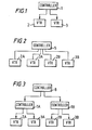
- Fig. 1 is a schematic block diagram of a controller 1 for controlling two video tape recorders (VTRs) 2 and 3 concurrently.
- the VTRs 2 and 3 are each connected to the controller 1 so as to enable input and output of video signals and operational commands to permit operations such as editing and the like to be performed.
- VTR video tape recorders
- the video tape recorders 2B and 3B could be connected to an additional controller 1B, and that controllers 1A and 1B could be controlled separately by a host controller 8 as illustrated schematically in Fig. 3.
- a host controller 8 as illustrated schematically in Fig. 3.
- a conventional controller such as that illustrated in Fig. 1 is able to control the pair of VTRs 2 and 3 in synchronism with each other such that information can be reproduced therefrom in a normal reproduction mode.
- the controller can reproduce information from the VTRs 2 and 3 at speeds sychronized with each other in normal reproduction mode.
- control data is provided from the controller to the VTR to switch its operating mode and, at the same time the control data is output to the other VTR.
- the VTRs can be set in a normal reproduction mode.
- the video tape recorders are operated with a predetermined reference signal taken as a reference so that they reproduce information in a synchronized manner.
- the operations of a plurality of the VTRs can be synchronized to output synchronized reproduction signals in the normal reproduction mode.
- the technique used as the normal reproduction mode is not suitable for synchronizing the reproduction of information from a plurality of video tape recorders at variable speeds due to small discrepancies in reproduction speed and differences in rise-time and fall-time characteristics between the video tape recorders.
- a solution is also sought to the problems associated with selecting a desired reproduction speed.
- An object of a first aspect of the invention is to provide a controller and a control system for controlling a plurality of controlled objects in an efficient and cost effective manner.
- a controller for controlling at least one reproduction apparatus wherein: the controller is connectable to at least one further controller to define a control system, which further controller is for controlling at least one further reproduction apparatus; the controller and the further controller are each selectively operable in a master mode or in a slave mode; and the controller is operable in the master mode to control the reproduction apparatus and to control, via the further controller, the further reproduction apparatus and is operable in the slave mode to permit the reproduction apparatus to be controlled by the further controller when the further controller is in the master mode.
- control system for controlling a plurality of reproduction apparatus, said control system comprising a plurality of controllers as defined above and connection means for interconnecting the controllers.
- control system for controlling a plurality of apparatus, said control system comprising a plurality of controllers and connection means for interconnecting the controllers wherein: each controller is connected to at least one apparatus for controlling said apparatus; each controller is selectively operable in a master mode or in a slave mode with at most one controller being operable in the master mode at any time; and an apparatus connected to a controller operating in the slave mode is controllable by a controller operating in the master mode.
- An object of a second aspect of the invention is to provide a controller which enables synchronized reproduction to be performed on a plurality of controlled devices (e.g. VTRs) at variable speeds.
- VTRs controlled devices
- a controller for controlling a reproduction speed of a first reproduction apparatus and a reproduction speed of a second reproduction apparatus by outputting a reproduction-speed control signal to the first reproduction apparatus and a reproduction-speed control signal to the second reproduction apparatus, the controller permitting control mode switching based on the reproduction-speed control signals to be performed and, for reproduction speeds within a predetermined range, the reproduction-speed control signals to be adjusted so that time information fed back by the first reproduction apparatus matches with time information fed back by the second reproduction apparatus.
- An object of a further aspect of the invention is to provide a convenient mechanism for selecting a variable speed for a controlled device such as a VTR.
- controller for controlling a reproduction apparatus comprising: reproduction-speed selecting means for selecting a value for the reproduction speed, a variable-speed dial for varying the reproduction speed, position detecting means for outputting rotational position information representing a rotational position of the variable-speed dial, reproduction-speed switching means for setting the reproduction speed in accordance with a selecting operation to a value determined by operating one of the reproduction-speed selecting apparatus or a value based on the rotational position information output by the position detecting means, and initializing means operable on selection of the variable-speed dial for initializing the rotational position information output by the position detecting means to a value corresponding to a reproduction speed prior to the selection of the variable-speed dial, and outputting the initialized rotational position information to the reproduction-speed switching means.
- a controller for a reproduction apparatus comprising: a variable-speed lever for varying a reproduction speed, first position detecting means for detecting a position of the variable-speed lever, a variable-speed dial for varying the reproduction speed, second position detecting means for detecting the rotational position of the variable-speed dial, and reproduction-speed switching means for switching the reproduction speed in accordance with detection results produced by the first position detecting means and the second position detecting means.
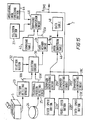
- Fig. 4 is a schematic block diagram of an editing system 10 in accordance with the invention which includes a plurality of controllers 12A, 12B, 12C, ... ..., 12N with a pair of video tape recorders 2A and 3A, 2B and 3B, 2C and 3C, ... ..., 2N and 3N connected respectively to each controller, the controllers being connected by a bus in the form of a general purpose interface bus (GP-IB) 14.
- GP-IB general purpose interface bus
- Each of the controllers can operate either in a master mode or in a slave mode.
- the controllers 12A to 12N can change the operation of the video tape recorders 2A to 2N connected to the controllers 12A to 12N according to control data D CONT input via the bus 14, and also change the operation of the video tape recorders 2A to 3N connected to the controllers 12A to 12N in accordance with the individual operation of each of the controllers 12A to 12N.
- Each of the controllers 12A to 12N is equipped with a master mode request means or master mode operator (e.g. a switch button 52 - see Fig. 18) for setting a master mode and a release operator (e.g. another switch button 54 - see Fig. 18) for releasing a master mode.
- master mode request means or master mode operator e.g. a switch button 52 - see Fig. 18
- release operator e.g. another switch button 54 - see Fig. 18
- the master mode and release operators are provided on an operating panel of the controller.
- the operating mode is changed to a master mode in accordance with a predetermined condition to be described below by operating the master mode operator.
- controllers 12A to 12N When one of the controllers 12A to 12N is in the master mode, it can output the control data D CONT to the other ones of the controllers 12A to 12N, which are in the slave mode, and change the operation of the video tape recorders 2A to 3N connected to those other controllers 12A to 12N.
- the editing system 10 is arranged such that the controllers 12A to 12N can be connected to the bus 14 and disconnected from the bus as required so that a desired number of video tape recorders can be connected in the editing system 10.
- This provides flexibility of connection of the controllers 12A to 12N with the result that a plurality of controlled objects (e.g. VTRs) can be controlled concurrently by means of a simple structure.
- control logic in a controller in the system 10 shown in Fig. 4 (this can be any one of the controllers 12A to 12N), for controlling a request by the controller to have its operating mode changed to a master mode, will now be described with reference to the flow chart of Fig. 5.
- the control logic initially shifts from a start step CP1 to a step CP2, in which the master mode operator is activated (e.g. by the user), and then the operation shifts to a step CP3 in which the request data REQ is output to the bus 14, and then to a step CP4 to start a monitoring timer for monitoring a predetermined period.
- the controllers 12A to 12N which are set to the slave mode, there will be no response to the request data REQ.
- the polling data POL will be sent back in response to the request data REQ.
- the operation mode of the controller concerned is changed in a step CP7 to the master mode only on condition that the polling data POL is not received by the controller (step CP5) in response to the request data REQ within a predetermined period set in a step CP6. Otherwise, the controller remains in the slave mode (step CP9) and the operation reaches an end step CP8.
- the controller comprises means (logic CP7) for sensing whether master mode acknowledgement data (the POL data) is received.
- Fig. 6 shows the operation of a controller (i.e. any of the controllers 12A to 12N) which had previously been set to the master mode.
- the process shifts from a start step CP10 to a step CP11 at a predetermined timing in which a decision is made whether or not the request data REQ is output from another controller to the bus 14, and if the request data REQ is not output, then the procedure shifts to a step CP12 to end the process.
- the request data REQ is sent, and then the bus 14 is monitored for a predetermined period to see whether or not the polling data POL is output onto the bus 14 by a controller already in the master mode, thereby deciding whether or not any of the controllers 12A to 12N has previously been set to the master mode.
- controllers 12A to 12N which has its master mode operator activated in the case where the polling data POL is not received in step CP5, a decision is made in step CP6 as to whether or not the monitoring timer indicates that the predetermined period has expired.
- controllers 12A to 12N return to step CP5, and a loop of steps CP5 - CP6 - CP5 is repeated until the predetermined period expires.
- step CP6 for the controller 12A, and, after shifting to step CP7, the controller 12A enters the master mode, and shifts to step CP8 to close the process.
- the one controller 12A only is set to the master mode, and the editing system 10 can be controlled entirely by the controller 12A in the master mode.
- Fig. 8 Another example is illustrated in Fig. 8 where the controller 12B is already set to the master mode.
- the polling data POL is sent back from the controller 12B before the period T of the monitoring timer expires, and hence anintertive result is obtained in step CP5 for the controller 12A.
- step CP9 where it is retained in the slave mode, and then shifts to step CP8 to close the process.
- the master mode is prevented from being established in another controller, and thus the editing system 10 can be controlled securely.
- Activating the release operator for a controller in master mode releases the master mode for that controller. It is then possible to activate the master mode operator of a desired controller to set the desired controller in the master mode to control the whole system.
- a controller 12A When a controller 12A previously set to the master mode powers up following an interruption of its power supply, it perform a process similar to that where the master mode operator is activated. In such a case, therefore, the controller 12A will adopt the master mode only where none of the controllers 12B to 12N is set to the master mode. This is illustrated in Fig. 9.
- any of controllers 12A to 12N previously set in the master mode before connection to the bus 14 will only adopt the master mode on the bus if no other of controllers 12A to 12N is currently set to the master mode.
- users are able to modify the editing system easily by connecting and disconnecting the controllers 12A to 12N arbitrarily, thus enhancing a serviceability of the whole editing system.
- a plurality of video tape recorders 2A to 4N connected to the controllers 12A to 12N can be controlled through a simple control structure in which the operating mode of the controllers 12A to 12N can be changed between a master mode and a slave mode over the bus 14.
- a controller requesting permission to enter the master mode outputs request data REQ and then tests for the return of polling data POL within a predetermined period, only when no polling data is received (i.e. none of the other controllers is already set to the master mode) does the requesting controller change from the slave mode to the master mode, avoiding mutual contention of the controllers 12A to 12N for controlling a plurality of the video tape recorders 2A to 3N.
- each controller may control only one video tape recorder which is connected thereto.
- each controller may control three or more video tape recorders connected thereto.
- controllers are connected by means of a general purpose interface bus (GP-IB)
- GP-IB general purpose interface bus
- the controllers could alternatively be connected through a bus such as RS232C, RS422 or the like. They could be connected through an exclusive bus or a two-way interface.
- controllers control video tape recorders as controlled objects.
- controlled objects could equally be in the form of a video disc player or the like.
- the reproduction of information is synchronized by controlling the apparatus so that timing information output by each of the apparatus for a speed set in a predetermined range matches each other.
- a controller 1 controls the operations of video tape recorders (VTRs) 2 and 3.
- the controller detects an amount of operation requested by a selector 5 (e.g. a variable-speed level 5) mounted on an operating panel of the controller.
- a command generating circuit 7 is responsive to a signal from the variable-speed lever 5 to output reproduction speed command data D COMD1 proportional to the amount of operation detected.
- the reproduction speed of the video tape recorder 2 is switched to a value in accordance to the amount of operation requested by the variable-speed lever 5.
- Buffer circuits 11 and 13 convert fed-back signals SMPTEs output by the video tape recorders 2 and 3 into time information data D T1 and D T2 respectively which are fed to a comparison circuit 15. A result of the comparison between the time information data D T1 and D T2 is then provided to a command generating circuit 17.
- the command generating circuit 17 generates reproduction speed control data D COMD2 based on the time codes D T1 and D T2 .
- the reproduction speed control data D COMD2 is output to the video tape recorder 3. Taking the time code D T1 as a reference, the video tape recorder 3 is thereby controlled. To be more specific, the reproduction speed of the video tape recorder 3 is controlled so that the time code D T2 matches the time code D T1 .
- the reproduction speed of the video tape recorder 3 is adjusted to that of the video tape recorder 2 by comparing the time information D T2 to D T1 . Accordingly, reproduction of information from the video tape recorders 2 and 3 can be synchronized even if the reproduction speeds are varied.
- time code D T1 output by the buffer circuit 11 of the controller 1 is made available externally. Therefore, reproduction of information from another video tape recorder can also be synchronized as well by connecting an external controller to a signal line conveying the time information D T1 .
- reproduction can be synchronized even if the reproduction speed is varied.
- pictures of the same object are reproduced from the video tape recorders 2 and 3 in a slow motion.
- the reproduced picture can be switched between the video tape recorders 2 and 3 without generating inharmonious motions in the reproduced pictures.
- such a controller can be used more easily and conveniently at a relay station, for example, for broadcasting a baseball game.
- the picture of a pitcher and that of a batter of a baseball game are to be displayed on the same screen in a slow motion.
- one operator operates a video tape recorder for reproducing the pitcher's picture while another operator operates another video tape recorder for reproducing the batter's picture in such a way that no inharmonious motion is seen on the screen.
- reproduced pictures can be switched between the video tape recorders 2 and 3 without the necessity for the operators to monitor both the pictures to be switched at the same time as is the case with the conventional apparatus. By monitoring only one of the two reproduced pictures, they can be switched. Accordingly excess monitoring apparatus can be eliminated, resulting in fewer monitoring systems and a simplified overall configuration.
- the reduced number of operators and the reduced number of monitoring apparatus required at the relaying site described above allow the small space available in the relaying car to be utilized efficiently and the work to be done in a more efficient manner.
- the video tape recorder 2 runs at a reproduction speed determined by a shift amount requested by the variable-speed lever 5. Its time information D T1 is fed back to the comparison circuit 15 through the buffer circuit 11.
- the video tape recorder 3 feeds back the time information D T2 to the comparison circuit 15 through the buffer circuit 13.
- the video tape recorder 3 is operating under the control of the reproduction speed control data D COMD2 output by the command generating circuit 17, the operation of which is, in turn, based on the comparison result produced by the comparison circuit 15.
- the reproduction speed of the video tape recorder 3 is adjusted so that the time code D T2 matches the time code D T1 and, thus, the reproduction of information from the video tape recorder 3 is synchronized with that from the video tape recorder 2.
- the reproduction speed control data D COMD2 is generated for controlling the reproduction speed of the video tape recorder 3.
- Fig. 11 shows an alternative to the arrangement shown in Fig. 10 using the same reference numerals used in that Figure.
- Reference numeral 20 shown in Fig. 11 is a controller for switching the control mode in accordance with the reproduction speed and correcting reproduction-speed control data D COMD by use of a command correcting circuit 22 for each control mode.
- the controller 20 executes a processing procedure shown in Fig. 12 once a predetermined period of time. As shown in Fig. 12, the processing procedures begins with an operation SP1 which is followed by an operation SP2 in which the position of a variable-speed lever 5 is detected.
- the reproduction-speed control data D COMD is produced by a command generating circuit 7 in a subsequent operation SP3.
- the controller 20 determines whether or not the reproduction speed determined by reproduction-speed corrected data D COMD of a command correcting circuit 21 is within a predetermined range.
- the controller 20 In the operation SP5, the controller 20 outputs the reproduction-speed control data D COMD to the video tape recorders 2 and 3 without modifying it by the command correcting circuit 21. Subsequently, the controller 20 moves forward to an operation SP6, completing the processing procedure.
- a video tape recorder exists which has an inferior characteristic in that the reproduction speed does not quickly follow the reproduction-speed control data D COMD . In this case, a corresponding change in the reproduction speed lags behind a variation in the reproduction-speed control data D COMD .
- control scheme is such that, by raising the reproduction speed and varying the reproduction speed frequently, a discrepancy of the order of a few frames between the video tape recorders 2 and 3 is inevitably not observed visually.
- the reproduction-speed control data D COMD is not corrected in one way or another by the command correcting circuit 21 for high reproduction speeds.
- the reproduction speeds of the video tape recorders 2 and 3 are controlled by outputting the reproduction-speed control data D COMD to the video tape recorders 2 and 3, not giving reproduction-speed responses to the operation of the variable-speed lever 5 the highest priority.
- the controller 20 proceed to an operation SP7.
- the operation SP7 checks whether the reproduction-speed control data D COMD output by the command correcting circuit 21 of the controller 20 is control data to halt the magnetic tapes of the video tape recorders 2 and 3. If an acknowledge response confirming that the reproduction-speed control data D COMD is control data halting the magnetic tapes, the processing procedure proceeds to an operation SP8. Based on time codes D T1 and D T2 , the operation SP8 adjusts the reproduction-speed control data D COMD .
- the controller 20 corrects the reproduction-speed control data D COMD so that the time code D T1 fed back by the video tape recorder 2 matches the time code D T2 fed back by the video tape recorder 3.
- the command correcting circuit 21 then outputs reproduction-speed control data D COMD1 and D COMD2 to the video tape recorders 2 and 3 respectively.
- the video tape recorders 2 and 3 halt the magnetic tapes at positions where the time codes D T1 and D T2 match each other completely. Subsequently, the controller 20 returns to the operation SP6, finishing the processing procedure.
- the video tape recorders 2 and 3 will carry out the slow-motion reproduction, with one of them starting with a frame different from the other, resulting in extremely inharmonious visual feeling in the observed pictures.
- the controller 20 executes an operation SP9.
- the controller 20 synchronizes the reproduction of picture from the video tape recorders 2 and 3 by correcting the reproduction-speed control data D COMD using the command correcting circuit 21.
- the command correcting circuit 22 outputs the reproduction-speed control data D COMD1 and D COMD2 to the video tape recorders 2 and 3 respectively so that the time code D T1 feed back by the video tape recorder 2 matches the time code D T2 fed back by the video tape recorder 3.
- the synchronized reproduction to reproduce pictures which are as a whole free of inharmonious motions is carried out by the operation SP9 only if the reproduction speed is determined by the operation SP4 to be within the predetermined range.
- the video tape recorders 2 and 3 receive the reproduction-speed control data D COMD from the command generating circuit 7 with no correction whatsoever, operating at a reproduction speed corresponding to a command given by the variable-speed lever 5.
- the controller 20 synchronizes the reproduction of pictures from the video tape recorders 2 and 3 by correcting the reproduction-speed control data D COMD using the command correcting circuit 22 which outputs the corrected reproduction-speed control data D COMD1 and D COMD2 to the video tape recorders 2 and 3 respectively so that the time code D T1 fed back by the video tape recorder 2 matches the time code D T2 fed back by the video tape recorder 3.
- the controller 20 can also correct the reproduction-speed control data D COMD , outputting the corrected reproduction-speed control data D COMD1 and D COMD2 to the video tape recorders 2 and 3 respectively so as t halt the magnetic tapes at positions where the time code D T1 fed back by the video tape recorder 2 completely matches the time code D T2 fed back by the video tape recorder 3 and then resumes the reproduction of pictures from the video tape recorders 2 and 3.
- the controller 20 synchronize the reproduction of pictures from the video tape recorders 2 and 3 by correcting the reproduction-speed control data D COMD using the command correcting circuit 22 in order to make the time code D T1 fed back by the video recorder 2 match the time code D T2 fed back by the video tape recorder 3, so that the synchronously reproduced pictures as a whole contain no inharmonious motions.
- the controller 20 in Fig. 11 controls reproduction speeds of first and second controlled devices (i.e. VTRs 2 and 3) by outputting reproduction-speed control signals (D COMD ) D COMD1 and D COMD2 to the controlled devices 2 and 3.
- the controller 20 Based on the reproduction-speed control signals (D COMD ) D COMD1 and D COMD2 , the controller 20 first switches the control mode of the controlled devices 2 and 3 so as to set their reproduction speeds within a predetermined range.
- the controller 20 then adjusts the reproduction control signals (D COMD ) D COMD1 and D COMD2 so that time information D T1 fed back by the controlled device 2 matches time information D T2 fed back by the controlled device 3.
- Figs. 10 to 12 utilize the SMPTE time code. It should be noted, however, that a variety of time codes are applicable. Furthermore, a variety of time information can also be used as a reference in addition to the time code.
- variable-speed lever as a means for adjusting the reproduction speed.
- invention is also applicable to a configuration employing a variable-speed dial as a means for adjusting the reproduction speed as will be explained hereinbelow.
- a video tape recorder is used as the controlled device.
- the controlled device need not be a VTR for the reproduction of pictures, but could also be a controlled device for example for variable-speed reproduction of information from a variety of video equipment.
- controllers which allow reproduction of information from controlled devices to be synchronized at a reproduction speed varying within a predetermined range; the devices being controlled by adjusting reproduction-speed control signals so that time information fed back by the device matches each other.
- the reproduction speed is first set to a predetermined value and then a variable-speed lever is adjusted in order to reproduce pictures at a desired reproduction speed.
- the controller of the proposed video tape recorder is equipped with an operational panel comprising a variable-speed lever operating button 27 in addition to reproduction-speed selecting buttons 22A, 22B and 22C as shown in Fig. 13.
- the variable-speed operating button 28 is used for switching the variable-speed lever 5 to an on state.
- the reproduction-speed selecting buttons 22A, 22B and 22C which are referred to hereafter as fixed-speed selecting buttons are used for setting the reproduction speed typically to a normal reproduction speed, half the normal reproduction speed or one-fifth of the normal reproduction speed.
- the video tape recorder runs at the normal reproduction speed, half the normal reproduction speed or one-fifth of the normal reproduction speed.
- a lever operation sensor 23 shown in Fig. 14 detects an amount of operation requested by the variable-speed lever 5, outputting a signal SEN which represents the amount of operation requested by the variable-speed lever 5 to a data memory circuit 26.
- a command converting circuit 14 accesses a command table 16, outputting the control command D COMD based on operation data D SEN , the signal SEN once stored in the data memory circuit 26.
- the reproduction speed of the video tape recorder is thus set to a value determined by the operation amount requested by the variable-speed lever 5.
- variable-speed operating button 27 is switched on and then the variable-speed lever 5 is operated, allowing the reproduction speed to be set to a desired value.
- variable-speed dial It has also been proposed to provide a video tape recorder with a rotary dial replacing the variable-speed lever 5.
- the rotary dial which is referred to hereafter as a variable-speed dial also allows the reproduction speed to be adjusted.
- variable-speed lever 5 generally makes the video tape recorder easier to operate in comparison to one with the variable-speed dial when used at a relay station, for example, for broadcasting a sport program such as a baseball game.
- variable-speed dial makes the video tape recorder easier to operate in comparison to a variable-speed lever 5 when used in a broadcasting station, for example, for editing work.
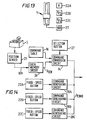
- Fig. 15 illustrates an overview of elements of a controller 29 in accordance with the invention for controlling a VTR, the controller including a variable-speed lever 5 for varying the reproduction speed with a first position detecting means 23 for detecting the position of the variable-speed lever 5 and a variable speed dial 24 for varying the reproduction speed with a second position detecting means 25 for detecting the rotational position of the variable-speed dial 24.
- Reproduction-speed switching means 26, 30, 32, 40 and 42 are provided for switching the reproduction speed in accordance with detection results SEN or SEN1 output by the first and second positional detecting arans 23 and 25 respectively.
- the controller also includes reproduction-speed selecting operation buttons 22A, 22B and 22C for selecting a value for the reproduction speed, the variable-speed dial 24 for varying the reproduction speed, the second position detecting means 25 for outputting the rotational position information SEN1 in accordance with the rotational position of the speed-variable dial 24, reproduction-speed switching means 27, 28A, 28B, 28C, 40 and 42 for setting the reproduction speed to a value based on the selection of the reproduction-speed selecting operation buttons 22A, 22B and 22C or rotational position information D SEN and initializing means 26, 46 and 48 for initializing the rotational position information SEN1 output by the position detecting means 25 in accordance with the reproduction speed set so ear and outputting the initial value to the reproduction-speed switching means 27, 28A, 28B, 28C, 40 and 42 when the variable-speed dial 24 is selected.
- variable-speed lever 5 and the variable-speed dial 24 are provided so as to allow the reproduction speed to be switched in accordance with information SEN or SEN1 which represents the position of the variable-speed lever 5 or the variable-speed dial 24 respectively. Accordingly, the operator can adjust the reproduction speed by using the variable-speed lever 5 or the variable-speed dial 24 as necessary.
- the fact that either the variable-speed lever 5 or the variable-speed dial 24 can be selected for adjusting the reproduction speed makes the reproducing apparatus easier to use.
- the second part of the invention allows the rotational position information SEN1 output by the second position detecting means 25 to be initialized in accordance with the reproduction speed set so far and the initial value to be output to the reproduction-speed switching means 27, 28A, 28B, 28C, 40 and 42. By doing this, an unnatural change in the reproduction speed that occurs right after the reproduction speed is selected can be eliminated effectively.
- buttons 22A, 22B and 22C are laid out on an operational panel of the controller 29, being sandwiched by a variable-speed lever 5 and the variable-speed dial 24.
- Light emitting diodes which serve as display lamps 31 and 33 are fixed below the variable-speed lever 5 and the variable-speed dial 24.
- a selection circuit 30 shown in Fig. 15 works in response to the operation of a selection button 32.
- a position sensor 23 and the rotational position sensor 25 detect the position of the variable-speed lever 5 and the rotational position of the variable-speed dial 24 respectively, outputting detection results SEN and SEN1 either of which is selected by the selection circuit 30 as an input to a data armory circuit 26.
- the selection circuit 30 switches on either the variable-speed lever 5 or the variable-speed dial 24, allowing the operator to adjust the reproduction speed by operating either the variable-speed lever 5 or the variable-speed dial 24.
- the selection circuit 30 turns on either the display lamp 31 or 33 depending upon whether the variable-speed lever 5 or the variable-speed dial 24 has been selected. In this way, the operator can visually identify which of the variable-speed lever 5 and the variable9-speed dial 24 has been selected with the selection button 27 turned on.
- variable-speed lever 5 or the variable-speed dial 24 for use in the adjustment of the reproduction speed by operating the selection button 27. Accordingly, the controller 20 of the video tape recorder becomes easier to use.
- a command conversion circuit 40 accesses a command table 42, outputting control data D COMD the magnitude of which is determined by the position of the variable-speed lever 6 or the rotational position of the variable-speed dial 24.
- the position of the variable-speed lever 5 or the rotational position of the variable-speed dial 24 is indicated by the position data SEN or by the rotational position data SEN1 respectively which is once stored in the data memory circuit 26.
- the control data D COMD sets the reproduction speed of the video tape recorder to a value determined by the position of the variable-speed lever 5 or the rotational position of the variable-speed dial 24.
- the command conversion circuit 40 accesses a different area of the command table 42, outputting the command data D COMD having a special value which causes the video tape recorder to rewind or run at a fast speed depending upon the rotational position of the variable-speed dial 24.
- variable-speed lever 5 or the variable-speed dial 24 By operating the variable-speed lever 5 or the variable-speed dial 24, it is thus possible for the operator not only to adjust the reproduction speed but also to search for head of the tape, for example.
- variable-speed lever 5 The operator who is used to a variable-speed lever 5 can thus operate the additional variable-speed dial 24 with ease if necessary for searching for a program, for example. In this way, the controller 29 of the video tape recorder is made easy to operate by the addition of the variable-speed dial 24.
- variable-speed lever 5 the operator who is not used to the operation of the variable-speed lever 5 can operate the controller 29 like a video tape recorder equipped with the conventional variable-speed dial in order to reproduce information free of inharmonious components.
- variable-speed lever 5 can be used as necessary for simplifying editing work, etc.
- a data conversion circuit 46 accesses a data table 48, converting the control data D COMD into rotational position data D KEN of the rotational position detecting sensor 22.
- the conversion performed by the data conversion circuit 46 is a reversed operation of the command conversion circuit 40.
- the data conversion circuit 46 then outputs the rotational position data D KEN to the data memory circuit 26, initializing the variable-speed dial 24.
- the data conversion circuit 46 updates the rotation position data SEN1 with the rotation position data D KEN which is transmitted to the command conversion circuit 40 from the memory circuit 12.
- control data D COMD output by the command conversion circuit 40 is a continuation of a value which was determined by the selected fixed-speed selecting button 22A, 22B or 22C immediately before the selection button 27 is turned on.
- variable-speed dial 24 is initialized with a value right after the operation is switched from the fixed-speed button 22A, 22B or 22C to the variable-speed dial 24.
- the initial value is equal to the reproduction speed prior to the switching of operation from the fixed-speed button 22A, 22B or 22C to the variable-speed dial 24. Accordingly, such an unnatural and abrupt change in the reproduction speed can be eliminated effectively.
- the data conversion circuit 46 further adjusts the rotational position data D SEN output by the data memory circuit 26 within a predetermined range having the rotational position data D KEN as a centre in accordance with the variation of the rotational position data SEN1.
- the data conversion circuit 46 sends a control signal to the variable-speed dial 24 in order to prevent the variable-speed dial 24 from further rotating.
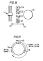
- variable-speed dial 24 can be initially rotated by 120 degrees in both the clockwise and counterclockwise directions from a centre point A as shown in Fig. 3. The operation is then switched to the fixed-speed selecting button 22A, 22B or 22C. When the operation is switched back to the variable-speed dial 24, the centre of rotation may be shifted from the point A to a new point B so that the variable-speed dial can now be rotated by 120 degrees in both the clockwise and counterclockwise directions from the new centre point B.
- variable-speed 24 can be rotated within a range which is predetermined by taking the initial value of the rotational data D SEN as a reference. The same adjustment range as that prior to the reselection of the variable-speed dial 24 can thus be retained.
- the operator can adjust the reproduction speed by rotating the variable-speed dial 24 without causing inharmonious feeling as if the variable-speed dial 24 had been selected by once presetting the variable-speed dial 24 to a position corresponding to a reproduction speed requested by the fixed-speed selecting button 22A, 22B or 22C.
- a position detecting sensor 23 works as a first position detecting means for detecting the position of the variable-speed lever 5 whereas the rotational-position detecting sensor 25 functions as a second position detecting means for detecting the rotational position of the variable-speed dial 24.
- the data memory circuit 26, the selection circuit 30, the selection button 32, the command conversion circuit 40 and the command table 42 constitute a reproduction-speed switching means for switching the reproduction speed in accordance with the detection result SEN or SEN1 output by the first or second position detecting means respectively.
- the fixed-speed buttons 22A, 22B and 22C form a reproduction speed selecting means for selecting a reproduction-speed while the rotational position detecting sensor 22 serves as a rotational position detecting means for outputting the rotational position information SEN1 which represents the rotational position of the variable-speed dial 24.
- the selection button 27, the command generating circuits 28A, 28B and 28C, the command conversion circuit 40 and the command table 42 together constitute a reproduction-speed switching arans for switching the reproduction speed in response to the operation of the selection button 27 to a value determined by the selection of the fixed-speed buttons 22A, 22B and 22C or to a value based on the rotational position information D SEN .
- the data memory circuits 26 the data conversion circuit 46 and the data table 48 together form an initializing means for initializing the rotational position information SEN1 output by the second position detecting means to a value equal to the reproduction speed being set so far and feeding the initial value to the reproduction-speed switching means whenever the variable-speed dial 24 is selected for adjusting the reproduction speed.
- the control data D COMD is output by the command generating circuits 28A, 28B or 28C associated with the fixed-speed button 22A, 22B or 22C respectively.
- information is reproduced from a magnetic tape moving at a reproduction speed determined by the fixed-speed button 22A, 22B or 22C.
- the position data SEN representing the position of the variable-speed lever 5 is output by the position detecting sensor 23 through the selection circuit 30.
- a command table 42 is accessed for eventually causing the command conversion circuit 40 to output the control data D COM having a value corresponding to a reproduction speed requested by the variable-speed lever 5. As a result, information can be reproduced at a desired reproduction speed by operating the variable-speed lever 5.
- the position data SEN1 having a value corresponding to a reproduction speed requested by the variable-speed dial 24 is output by the rotational-position detecting sensor 25 through the selection circuit 30.
- the position data SEN1 eventually causes the command conversion circuit 40 to output the control data D COMD having a value corresponding to a reproduction speed requested by the variable-speed dial 24. As a result, information can be reproduced at a desired reproduction speed by operating the variable-speed dial 24.
- variable-speed lever 5 or the variable-speed dial 24 can be selected as necessary for adjusting the reproduction speed, allowing the video tape recorder to be used more easily.
- the rotational position data D KEN having a value corresponding to the reproduction speed being set so far is output by the data conversion circuit 46.
- the rotational position data D KEN is used to update the rotational position data D SEN output by the data memory circuit 27.
- variable-speed dial 24 is initialized, causing the video tape recorder to retain the reproduction speed being set so far in case the operation is switched to the variable-speed dial 24.
- the reproduction speed of the video tape recorder is adjusted by manipulating the variable-speed dial 24 with the reproduction speed prior to the switching of the operation taken as a start point. Accordingly, an abrupt and unnatural change in the reproduction speed that would otherwise occur upon the selection of the variable-speed dial 24 can be virtually eliminated.
- variable-speed lever 5 or the variable-speed dial 24 allows either the variable-speed lever 5 or the variable-speed dial 24 to be selected for use in adjusting the reproduction speed. It is thus possible to make the video tape recorder easier to use by virtue of the feature that allows either the variable-speed lever 5 or the variable-speed dial 24 to be selected.
- variable-speed dial 24 is initialized right after being selected to a value corresponding to the reproduction speed prior to the selection of the variable-speed dial 24, allowing an abrupt and unnatural change in the reproduction speed that would otherwise occur upon the selection of the variable-speed dial 24 to be effectively eliminated.
- variable-speed dial 24 is initialized by updating the rotational position SEN1 once stored in the data armory circuit 12 with the rotational position data D KEN output by the data conversion circuit 46.
- initialisation techniques can also be applied as well as the initializing arans described herein.
- the invention is applied to a video tape recorder. It should be noted, however, that the invention is applicable not only to video tape recorders but also to a wide range of reproduction devices operating at variable speeds, such as a video disc player.
- Fig. 16 is a schematic diagram of a control panel 50 of an example of a controller in accordance with the invention.
- the control panel 50 comprises many controls not relevant to the present invention, and accordingly are not described herein.
- the control panel comprises a selection button 27 for selecting either a variable-speed lever 6 or a variable speed dial 24.
- the controller comprises a plurality of buttons 22A, 22B and 22C for selecting variable speeds.
- the controller comprises a button 52 for requesting that the controller operates in master mode and a button 54 for deselecting master mode.
- a controller for controlling predetermined controlled objects the improvement characterized in that: said controller is connected to external controllers of a construction; said controlled objects connected to said external controllers and said controlled objects connected to said controller are controlled through said external controllers in a master mode; said controlled objects connected to said controller are controlled in accordance with said external controllers set to the master mode in a slave mode.
- a controller for controlling predetermined controlled objects the improvement characterized in that: said controller is connected to external controllers of a construction; an operation mode is changed into a master mode and a slave mode; a request data is answered according to said operation mode; a request data is answered according to said operation mode; said request data is outputted to said external controllers when leading to the master mode, and according to answers of said external controllers, said master mode is so led when said external controllers are not set to the master mode, and the slave mode is kept when said external controllers are set to the master mode; said controlled objects connected to said external controllers and said controlled objects connected to said controller are controlled through said external controllers in the master mode; said controlled objects connected to said controller are controlled in accordance with said external controllers set to the master mode in the slave mode.
- controller for controlling the reproduction speed of a first controlled device and the reproduction speed of a second controlled device by outputting a reproduction-speed control signal to said first controlled device and a reproduction-speed control signal to said second controlled device, said controller being characterized by allowing control mode switching based on said reproduction-speed control signals to be performed and, for reproduction speeds within a predetermined range, said reproduction-speed control signals to be adjusted so that time information fed back by said first controlled device matches with time infomation fed back by said second controlled device.
- a reproducing apparatus characterized by comprising: a variable-speed lever for varying the reproduction speed, a first position detecting means for detecting the position of said variable-speed lever, a variable-speed dial for varying the reproduction speed, a second position detecting means for detecting the rotational position of said variable-speed dial, and a reproduction-speed switching means for switching the reproduction speed in accordance with detection results produced by said first position detecting means and said second position detecting means.
- a reproducing apparatus characterized by comprising: reproduction-speed selecting devices for selecting a value for the reproduction speed, a variable-speed dial for varying the reproduction speed, a position detecting means for outputting rotational position information representing the rotational position of said variable-speed dial, a reproduction-speed switching means for setting the reproduction speed in accordance with a selecting operation to a value determined by operating one of said reproduction-speed selecting devices or a value based on the rotational position information output by said position detecting means, and an initializing arans used upon an operation to select said variable-speed dial for initializing the rotational position information output by said position detecting means to a value corresponding to the reproduction speed prior to the selection of said variable-speed dial, and outputting the initialized rotational position information to said reproduction-speed switching means.
Abstract
Description
- The invention relates to controllers and control systems in general and to controllers and control systems for controlling reproduction devices such as video tape recorders (VTRs) in particular.
- Fig. 1 is a schematic block diagram of a controller 1 for controlling two video tape recorders (VTRs) 2 and 3 concurrently. The
VTRs - It is desired that more than two VTRs be connected in this manner, then this causes difficulties. The video tape recorders (VTR) 2 and 3 are each connected to the controller 1 for inputting and outputting video signals and operational commands for enabling operations such as editing or the like.
- Conceivably four
video tape recorders single controller 5 were capable of controlling thevideo tape recorders video tape recorders 2A and 3A, as illustrated schematically in Fig. 2. However, such an arrangement where manyvideo tape recorders 2A to 3B are connected to a common controller would mean that the construction of thecontroller 5 would become complicated. - Alternatively, it is conceivable that the
video tape recorders additional controller 1B, and thatcontrollers host controller 8 as illustrated schematically in Fig. 3. However, this leads to the need for theextra host controller 8. - There are additional problems associated with conventional controllers and control systems. A conventional controller such as that illustrated in Fig. 1 is able to control the pair of
VTRs VTRs - With the conventional controller, the operations of a plurality of the VTRs can be synchronized to output synchronized reproduction signals in the normal reproduction mode.
- A problem arises where it is desired to synchronize the reproduction of information from a plurality of video tape recorders at variable speeds, as for example would be desirable for a relay station, for example, for broadcasting a baseball game.
- The technique used as the normal reproduction mode is not suitable for synchronizing the reproduction of information from a plurality of video tape recorders at variable speeds due to small discrepancies in reproduction speed and differences in rise-time and fall-time characteristics between the video tape recorders.
- A solution is also sought to the problems associated with selecting a desired reproduction speed.
- An object of a first aspect of the invention is to provide a controller and a control system for controlling a plurality of controlled objects in an efficient and cost effective manner.
- In accordance with a first aspect of the invention, therefore, there is provided a controller for controlling at least one reproduction apparatus, wherein:
the controller is connectable to at least one further controller to define a control system, which further controller is for controlling at least one further reproduction apparatus;
the controller and the further controller are each selectively operable in a master mode or in a slave mode; and
the controller is operable in the master mode to control the reproduction apparatus and to control, via the further controller, the further reproduction apparatus and is operable in the slave mode to permit the reproduction apparatus to be controlled by the further controller when the further controller is in the master mode. - There is also provided a control system for controlling a plurality of reproduction apparatus, said control system comprising a plurality of controllers as defined above and connection means for interconnecting the controllers.
- Although the invention is particularly adapted to the control of reproducing devices such as video tape recorders, it is not limited thereto. Accordingly, there is also provided a control system for controlling a plurality of apparatus, said control system comprising a plurality of controllers and connection means for interconnecting the controllers wherein:
each controller is connected to at least one apparatus for controlling said apparatus;
each controller is selectively operable in a master mode or in a slave mode with at most one controller being operable in the master mode at any time; and
an apparatus connected to a controller operating in the slave mode is controllable by a controller operating in the master mode. - An object of a second aspect of the invention is to provide a controller which enables synchronized reproduction to be performed on a plurality of controlled devices (e.g. VTRs) at variable speeds.
- In accordance with a second aspect of the invention, therefore, there is provided a controller for controlling a reproduction speed of a first reproduction apparatus and a reproduction speed of a second reproduction apparatus by outputting a reproduction-speed control signal to the first reproduction apparatus and a reproduction-speed control signal to the second reproduction apparatus, the controller permitting control mode switching based on the reproduction-speed control signals to be performed and, for reproduction speeds within a predetermined range, the reproduction-speed control signals to be adjusted so that time information fed back by the first reproduction apparatus matches with time information fed back by the second reproduction apparatus.
- An object of a further aspect of the invention is to provide a convenient mechanism for selecting a variable speed for a controlled device such as a VTR.
- In accordance with a third aspect of the invention, therefore, there is provided controller for controlling a reproduction apparatus comprising:
reproduction-speed selecting means for selecting a value for the reproduction speed,
a variable-speed dial for varying the reproduction speed,
position detecting means for outputting rotational position information representing a rotational position of the variable-speed dial,
reproduction-speed switching means for setting the reproduction speed in accordance with a selecting operation to a value determined by operating one of the reproduction-speed selecting apparatus or a value based on the rotational position information output by the position detecting means, and
initializing means operable on selection of the variable-speed dial for initializing the rotational position information output by the position detecting means to a value corresponding to a reproduction speed prior to the selection of the variable-speed dial, and outputting the initialized rotational position information to the reproduction-speed switching means. - There is also provided a controller for a reproduction apparatus comprising:
a variable-speed lever for varying a reproduction speed,
first position detecting means for detecting a position of the variable-speed lever,
a variable-speed dial for varying the reproduction speed,
second position detecting means for detecting the rotational position of the variable-speed dial, and
reproduction-speed switching means for switching the reproduction speed in accordance with detection results produced by the first position detecting means and the second position detecting means. - Preferred embodiments of the invention are described hereinafter with reference to the accompanying drawings in which:
- Fig. 1 is a schematic diagram of a prior art controller for controlling two video tape recorders;
- Figs. 2 and 3 are schematic block diagrams of conceivable control systems;
- Fig. 4 is a schematic block diagram of a control system in accordance with the invention;
- Figs. 5 and 6 are flow diagrams illustrating control logic incorporated in controllers in the control system of Fig. 4;
- Figs. 7, 8 and 9 are state diagrams for illustrating operations of the control system of Fig. 4;
- Fig. 10 is a schematic block diagram of elements one example of a controller for the control system of Fig. 4;
- Fig. 11 is a schematic block diagram of elements of a second example of a controller;
- Fig. 12 is a flow chart showing the principle of operation of the controller of Fig. 11;
- Fig. 13 is a schematic illustration of part of a control panel for a proposal for a controller;
- Fig. 14 is a schematic block diagram of elements of the controller of Fig. 13;
- Fig. 15 is a schematic block diagram of elements of an example of a controller in accordance with the invention;
- Fig. 16 is an illustration of part of a control panel of the controller of Fig. 15;
- Fig. 17 is used in explaining the initialisation of a variable-speed dial of the controller of Fig. 15; and
- Fig. 18 is an illustration of elements of a control panel in accordance with the invention.
- Fig. 4 is a schematic block diagram of an
editing system 10 in accordance with the invention which includes a plurality ofcontrollers video tape recorders - In a slave mode, the
controllers 12A to 12N can change the operation of thevideo tape recorders 2A to 2N connected to thecontrollers 12A to 12N according to control data DCONT input via thebus 14, and also change the operation of thevideo tape recorders 2A to 3N connected to thecontrollers 12A to 12N in accordance with the individual operation of each of thecontrollers 12A to 12N. - Each of the
controllers 12A to 12N is equipped with a master mode request means or master mode operator (e.g. a switch button 52 - see Fig. 18) for setting a master mode and a release operator (e.g. another switch button 54 - see Fig. 18) for releasing a master mode. The master mode and release operators are provided on an operating panel of the controller. The operating mode is changed to a master mode in accordance with a predetermined condition to be described below by operating the master mode operator. - When one of the
controllers 12A to 12N is in the master mode, it can output the control data DCONT to the other ones of thecontrollers 12A to 12N, which are in the slave mode, and change the operation of thevideo tape recorders 2A to 3N connected to thoseother controllers 12A to 12N. - Thus in the
editing system 10, when one of thecontrollers 12A to 12N is set to the master mode, it can control theentire editing system 10. - The
editing system 10 is arranged such that thecontrollers 12A to 12N can be connected to thebus 14 and disconnected from the bus as required so that a desired number of video tape recorders can be connected in theediting system 10. This provides flexibility of connection of thecontrollers 12A to 12N with the result that a plurality of controlled objects (e.g. VTRs) can be controlled concurrently by means of a simple structure. - The detailed operation of control logic in a controller in the
system 10 shown in Fig. 4 (this can be any one of thecontrollers 12A to 12N), for controlling a request by the controller to have its operating mode changed to a master mode, will now be described with reference to the flow chart of Fig. 5. As shown in Fig. 5, in thecontroller 12A to 12N, the control logic initially shifts from a start step CP1 to a step CP2, in which the master mode operator is activated (e.g. by the user), and then the operation shifts to a step CP3 in which the request data REQ is output to thebus 14, and then to a step CP4 to start a monitoring timer for monitoring a predetermined period. - In the other ones of the
controllers 12A to 12N which are set to the slave mode, there will be no response to the request data REQ. However, in thecontrollers 12A to 12N which have previously been set to the master mode, the polling data POL will be sent back in response to the request data REQ. The operation mode of the controller concerned is changed in a step CP7 to the master mode only on condition that the polling data POL is not received by the controller (step CP5) in response to the request data REQ within a predetermined period set in a step CP6. Otherwise, the controller remains in the slave mode (step CP9) and the operation reaches an end step CP8. In other words the controller comprises means (logic CP7) for sensing whether master mode acknowledgement data (the POL data) is received. - Fig. 6, shows the operation of a controller (i.e. any of the
controllers 12A to 12N) which had previously been set to the master mode. The process shifts from a start step CP10 to a step CP11 at a predetermined timing in which a decision is made whether or not the request data REQ is output from another controller to thebus 14, and if the request data REQ is not output, then the procedure shifts to a step CP12 to end the process. - On the other hand, when the request data REQ has been output from another controller to the
bus 14, a positive result is obtained in the step CP11 and the controller already in the master mode shifts to a step CP13 to output the polling data POL, and then shifts to the step CP12 to end the process. - Thus in any of the
controllers 12A to 12N in which the master mode operator is activated, the request data REQ is sent, and then thebus 14 is monitored for a predetermined period to see whether or not the polling data POL is output onto thebus 14 by a controller already in the master mode, thereby deciding whether or not any of thecontrollers 12A to 12N has previously been set to the master mode. - Accordingly, as a result of changing the operation mode to the master mode only on condition that the polling data POL is not received, no more than one of the
controllers 12A to 12N of those which are connected to thebus 14 can be set to the master mode at any one time. - Also, by changing the operation mode of a controller into the master mode only on condition that the polling data POL is not received, thus preventing a plurality of
controllers 12A to 12N from changing to the master mode concurrently, mutual contention of thecontrollers 12A to 12N can be prevented and theediting system 10 can be controlled entirely securely. - In any of
controllers 12A to 12N which has its master mode operator activated in the case where the polling data POL is not received in step CP5, a decision is made in step CP6 as to whether or not the monitoring timer indicates that the predetermined period has expired. - If the predetermined period has expired, then the
controllers 12A to 12N return to step CP5, and a loop of steps CP5 - CP6 - CP5 is repeated until the predetermined period expires. - An example of this process will now be described for a situation where the master mode operator of the
controller 12A is activated where thecontrollers 12A to 12N are all set to the slave mode. As illustrated in Fig. 7, the request data REQ is outputted from thecontroller 12A, but no polling data POL is sent back within the predetermined period T. As a result of this an affirmative result is obtained in step CP6 for thecontroller 12A, and, after shifting to step CP7, thecontroller 12A enters the master mode, and shifts to step CP8 to close the process. - Thus, among the
controllers 12A to 12N, the onecontroller 12A only is set to the master mode, and theediting system 10 can be controlled entirely by thecontroller 12A in the master mode. - Another example is illustrated in Fig. 8 where the
controller 12B is already set to the master mode. In this case, the polling data POL is sent back from thecontroller 12B before the period T of the monitoring timer expires, and hence an afirmative result is obtained in step CP5 for thecontroller 12A. - In this example, therefore, the
controller 12A shifts to step CP9 where it is retained in the slave mode, and then shifts to step CP8 to close the process. - Thus, where one of the
controllers 12A to 12N is already set to the master mode, the master mode is prevented from being established in another controller, and thus theediting system 10 can be controlled securely. - Activating the release operator for a controller in master mode releases the master mode for that controller. It is then possible to activate the master mode operator of a desired controller to set the desired controller in the master mode to control the whole system.
- When a
controller 12A previously set to the master mode powers up following an interruption of its power supply, it perform a process similar to that where the master mode operator is activated. In such a case, therefore, thecontroller 12A will adopt the master mode only where none of thecontrollers 12B to 12N is set to the master mode. This is illustrated in Fig. 9. - That is, even in the case where the power supply to one or more of the
controllers 12A to 12N is cut where thecontrollers 12A to 12N are connected to thebus 14, any ofcontrollers 12A to 12N previously set in the master mode before connection to thebus 14 will only adopt the master mode on the bus if no other ofcontrollers 12A to 12N is currently set to the master mode. - Thus, in a case where the video tape recorders are reconnected, for example, after modifying the editing system, a mutual contention of the
controllers 12A to 12N will be avoided, and then a plurality of video tape recorders can be controlled without a complex control structure. - Accordingly, users are able to modify the editing system easily by connecting and disconnecting the
controllers 12A to 12N arbitrarily, thus enhancing a serviceability of the whole editing system. - As described above, a plurality of
video tape recorders 2A to 4N connected to thecontrollers 12A to 12N can be controlled through a simple control structure in which the operating mode of thecontrollers 12A to 12N can be changed between a master mode and a slave mode over thebus 14. - In the sequence of operations described where a controller requesting permission to enter the master mode outputs request data REQ and then tests for the return of polling data POL within a predetermined period, only when no polling data is received (i.e. none of the other controllers is already set to the master mode) does the requesting controller change from the slave mode to the master mode, avoiding mutual contention of the
controllers 12A to 12N for controlling a plurality of thevideo tape recorders 2A to 3N. - In the above-described embodiment, two video tape recorders are connected to each controller. However, each controller may control only one video tape recorder which is connected thereto. Similarly, each controller may control three or more video tape recorders connected thereto.
- Further, in the above-described embodiment, the controllers are connected by means of a general purpose interface bus (GP-IB) However, the controllers could alternatively be connected through a bus such as RS232C, RS422 or the like. They could be connected through an exclusive bus or a two-way interface.
- Still further, in the embodiment described above, the controllers control video tape recorders as controlled objects. However, the controlled objects could equally be in the form of a video disc player or the like.
- Aspects of a controller for allowing the reproduction of information from a plurality of controlled devices (e.g. VTRs) to be synchronized, even if the reproduction speed is changed, will now be described. The reproduction of information is synchronized by controlling the apparatus so that timing information output by each of the apparatus for a speed set in a predetermined range matches each other.
- One example of a controller for providing synchronized reproduction to be performed on a plurality of VTRs at a variable speed is illustrated in Fig. 10. As shown in Fig. 10, a controller 1 controls the operations of video tape recorders (VTRs) 2 and 3.
- The controller detects an amount of operation requested by a selector 5 (e.g. a variable-speed level 5) mounted on an operating panel of the controller. A
command generating circuit 7 is responsive to a signal from the variable-speed lever 5 to output reproduction speed command data DCOMD1 proportional to the amount of operation detected. As a result, the reproduction speed of thevideo tape recorder 2 is switched to a value in accordance to the amount of operation requested by the variable-speed lever 5. -
Buffer circuits video tape recorders comparison circuit 15. A result of the comparison between the time information data DT1 and DT2 is then provided to acommand generating circuit 17. - The
command generating circuit 17 generates reproduction speed control data DCOMD2 based on the time codes DT1 and DT2. The reproduction speed control data DCOMD2 is output to thevideo tape recorder 3. Taking the time code DT1 as a reference, thevideo tape recorder 3 is thereby controlled. To be more specific, the reproduction speed of thevideo tape recorder 3 is controlled so that the time code DT2 matches the time code DT1. - In this way, the reproduction speed of the
video tape recorder 3 is adjusted to that of thevideo tape recorder 2 by comparing the time information DT2 to DT1. Accordingly, reproduction of information from thevideo tape recorders - In addition, the time code DT1 output by the
buffer circuit 11 of the controller 1 is made available externally. Therefore, reproduction of information from another video tape recorder can also be synchronized as well by connecting an external controller to a signal line conveying the time information DT1. - In this way, reproduction can be synchronized even if the reproduction speed is varied. For example, pictures of the same object are reproduced from the
video tape recorders video tape recorders - Accordingly, such a controller can be used more easily and conveniently at a relay station, for example, for broadcasting a baseball game.
- For example, the picture of a pitcher and that of a batter of a baseball game are to be displayed on the same screen in a slow motion. In this case, with the conventional apparatus, one operator operates a video tape recorder for reproducing the pitcher's picture while another operator operates another video tape recorder for reproducing the batter's picture in such a way that no inharmonious motion is seen on the screen.
- With the reproducing apparatus provided, however, a single operator can synchronize reproduction of pictures at a variable speed with ease by merely operating the variable-
speed lever 5 to give reproduced pictures free of inharmonious motions. - Since reproduction of pictures can be synchronized, reproduced pictures can be switched between the
video tape recorders - Particularly, in the case of a relaying car with limited space for accommodating relaying equipment, the reduced number of operators and the reduced number of monitoring apparatus required at the relaying site described above allow the small space available in the relaying car to be utilized efficiently and the work to be done in a more efficient manner.
- In the configuration described above, receiving the reproduction speed control data DCOMD1 output by the
command generating circuit 7, thevideo tape recorder 2 runs at a reproduction speed determined by a shift amount requested by the variable-speed lever 5. Its time information DT1 is fed back to thecomparison circuit 15 through thebuffer circuit 11. - The
video tape recorder 3 feeds back the time information DT2 to thecomparison circuit 15 through thebuffer circuit 13. At the saar time, thevideo tape recorder 3 is operating under the control of the reproduction speed control data DCOMD2 output by thecommand generating circuit 17, the operation of which is, in turn, based on the comparison result produced by thecomparison circuit 15. The reproduction speed of thevideo tape recorder 3 is adjusted so that the time code DT2 matches the time code DT1 and, thus, the reproduction of information from thevideo tape recorder 3 is synchronized with that from thevideo tape recorder 2. - In the above configuration, based on the comparison result between the time codes DT1 and DT2 of the
video tape recorders video tape recorder 3. As a result, with only a simple apparatus configuration, reproduction of pictures can be synchronized even at a variable reproduction speed. - Fig. 11 shows an alternative to the arrangement shown in Fig. 10 using the same reference numerals used in that Figure.
Reference numeral 20 shown in Fig. 11 is a controller for switching the control mode in accordance with the reproduction speed and correcting reproduction-speed control data DCOMD by use of a command correcting circuit 22 for each control mode. - To be more specific, the
controller 20 executes a processing procedure shown in Fig. 12 once a predetermined period of time. As shown in Fig. 12, the processing procedures begins with an operation SP1 which is followed by an operation SP2 in which the position of a variable-speed lever 5 is detected. The reproduction-speed control data DCOMD is produced by acommand generating circuit 7 in a subsequent operation SP3. - Entering the next operation SP4, the
controller 20 determines whether or not the reproduction speed determined by reproduction-speed corrected data DCOMD of acommand correcting circuit 21 is within a predetermined range. - If a
video tape recorder - In the operation SP5, the
controller 20 outputs the reproduction-speed control data DCOMD to thevideo tape recorders command correcting circuit 21. Subsequently, thecontroller 20 moves forward to an operation SP6, completing the processing procedure. - A video tape recorder exists which has an inferior characteristic in that the reproduction speed does not quickly follow the reproduction-speed control data DCOMD. In this case, a corresponding change in the reproduction speed lags behind a variation in the reproduction-speed control data DCOMD.
- Accordingly, in the case of such video tape recorders, even if the reproduction-speed control data DCOMD is output so that the time codes match each other as in the case with the first embodiment, a change in the reproduction speed lags behind a command given by the user's operation on the variable-
speed lever 5. As a result, an inharmonious movement is seen in the reproduction picture when the user manipulates the variable-speed lever 5. - With regard to the inharmonious feeling resulted in by the operation of the variable-
speed lever 5, however, the control scheme is such that, by raising the reproduction speed and varying the reproduction speed frequently, a discrepancy of the order of a few frames between thevideo tape recorders - Accordingly, in this example, the reproduction-speed control data DCOMD is not corrected in one way or another by the
command correcting circuit 21 for high reproduction speeds. In this case, the reproduction speeds of thevideo tape recorders video tape recorders speed lever 5 the highest priority. - However, if the reproduction speed is determined by the operation SP4 to be within the predetermined range, the
controller 20 proceed to an operation SP7. - The operation SP7 checks whether the reproduction-speed control data DCOMD output by the
command correcting circuit 21 of thecontroller 20 is control data to halt the magnetic tapes of thevideo tape recorders - To be more specific, using the
command correcting circuit 21, thecontroller 20 corrects the reproduction-speed control data DCOMD so that the time code DT1 fed back by thevideo tape recorder 2 matches the time code DT2 fed back by thevideo tape recorder 3. Thecommand correcting circuit 21 then outputs reproduction-speed control data DCOMD1 and DCOMD2 to thevideo tape recorders video tape recorders controller 20 returns to the operation SP6, finishing the processing procedure. - If slow-motion reproduction is resumed after halting the
video tape recorders video tape recorders - On the other hand, if slow-motion reproduction is resumed after halting the magnetic tapes of the
video tape recorders video tape recorders - If a response which denies control data for halting the magnetic tapes of the
video tape recorders controller 20 executes an operation SP9. - In the operation SP9, the
controller 20 synchronizes the reproduction of picture from thevideo tape recorders command correcting circuit 21. The command correcting circuit 22 outputs the reproduction-speed control data DCOMD1 and DCOMD2 to thevideo tape recorders video tape recorder 2 matches the time code DT2 fed back by thevideo tape recorder 3. - In this way, for low reproduction speeds, since the frame of the
video tape recorder 2 is controlled to match the frame of thevideo tape recorder 3, pictures can be reproduced with no inharmonioous motions even if thevideo tape recorders speed lever 5. - Accordingly, by synchronizing the picture reproduction, pictures can be reproduced with no observed inharmonious motions.
- The synchronized reproduction to reproduce pictures which are as a whole free of inharmonious motions is carried out by the operation SP9 only if the reproduction speed is determined by the operation SP4 to be within the predetermined range.
- In this configuration, for high reproduction speeds, the
video tape recorders command generating circuit 7 with no correction whatsoever, operating at a reproduction speed corresponding to a command given by the variable-speed lever 5. - For low reproduction speeds within the predetermined range, however, the
controller 20 synchronizes the reproduction of pictures from thevideo tape recorders video tape recorders video tape recorder 2 matches the time code DT2 fed back by thevideo tape recorder 3. - It is thus possible to synchronize the reproduction of pictures from the
video tape recorders speed lever 5 by performing control so that the time code DT1 fed back by thevideo tape recorder 2 matches the time code DT2 fed back by thevideo tape recorder 3. - In addition, using the
command correcting circuit 21, thecontroller 20 can also correct the reproduction-speed control data DCOMD, outputting the corrected reproduction-speed control data DCOMD1 and DCOMD2 to thevideo tape recorders video tape recorder 2 completely matches the time code DT2 fed back by thevideo tape recorder 3 and then resumes the reproduction of pictures from thevideo tape recorders - With the configuration shown in Fig. 11, only for low reproduction speeds within a predetermine range, does the
controller 20 synchronize the reproduction of pictures from thevideo tape recorders video recorder 2 match the time code DT2 fed back by thevideo tape recorder 3, so that the synchronously reproduced pictures as a whole contain no inharmonious motions. - Thus the
controller 20 in Fig. 11 controls reproduction speeds of first and second controlled devices (i.e.VTRs 2 and 3) by outputting reproduction-speed control signals (DCOMD) DCOMD1 and DCOMD2 to the controlleddevices controller 20 first switches the control mode of the controlleddevices controller 20 then adjusts the reproduction control signals (DCOMD) DCOMD1 and DCOMD2 so that time information DT1 fed back by the controlleddevice 2 matches time information DT2 fed back by the controlleddevice 3. - By correcting the reproduction speed control signals (DCOMD) DCOMD1 and DCOMD2 and outputting the reproduction speed control signals (DCOMD) DCOMD1 and DCOMD2 to the first and second controlled
devices device 2 matches the time information DT2 fed back by the second controlleddevice 3, the reproduction of information can be synchronized even if the reproduction speed is varied. - The examples described with reference to Figs. 10 to 12 utilize the SMPTE time code. It should be noted, however, that a variety of time codes are applicable. Furthermore, a variety of time information can also be used as a reference in addition to the time code.
- The embodiments described above adopt a variable-speed lever as a means for adjusting the reproduction speed. In addition, the invention is also applicable to a configuration employing a variable-speed dial as a means for adjusting the reproduction speed as will be explained hereinbelow.
- Also, in the embodiments described above, a video tape recorder is used as the controlled device. Note, however, that the controlled device need not be a VTR for the reproduction of pictures, but could also be a controlled device for example for variable-speed reproduction of information from a variety of video equipment.
- Examples of controllers have been described which allow reproduction of information from controlled devices to be synchronized at a reproduction speed varying within a predetermined range; the devices being controlled by adjusting reproduction-speed control signals so that time information fed back by the device matches each other.
- Aspects of a controller for a playback device such as a VTR which is operable at a variable speed will now be described.
- In one proposal for video tape recorder allowing pictures to be reproduced at a variable speed, the reproduction speed is first set to a predetermined value and then a variable-speed lever is adjusted in order to reproduce pictures at a desired reproduction speed.
- To be more specific, the controller of the proposed video tape recorder is equipped with an operational panel comprising a variable-speed
lever operating button 27 in addition to reproduction-speed selecting buttons speed lever 5 to an on state. The reproduction-speed selecting buttons - When the fixed-
speed selecting button command generating circuit speed selecting button - A
lever operation sensor 23 shown in Fig. 14 detects an amount of operation requested by the variable-speed lever 5, outputting a signal SEN which represents the amount of operation requested by the variable-speed lever 5 to adata memory circuit 26. - With the variable-
speed operating button 27 switched on, acommand converting circuit 14 accesses a command table 16, outputting the control command DCOMD based on operation data DSEN, the signal SEN once stored in thedata memory circuit 26. The reproduction speed of the video tape recorder is thus set to a value determined by the operation amount requested by the variable-speed lever 5. - In this way, the variable-
speed operating button 27 is switched on and then the variable-speed lever 5 is operated, allowing the reproduction speed to be set to a desired value. - It has also been proposed to provide a video tape recorder with a rotary dial replacing the variable-
speed lever 5. The rotary dial which is referred to hereafter as a variable-speed dial also allows the reproduction speed to be adjusted. - The variable-
speed lever 5 generally makes the video tape recorder easier to operate in comparison to one with the variable-speed dial when used at a relay station, for example, for broadcasting a sport program such as a baseball game. - On the other hand, a variable-speed dial makes the video tape recorder easier to operate in comparison to a variable-
speed lever 5 when used in a broadcasting station, for example, for editing work. - Fig. 15 illustrates an overview of elements of a controller 29 in accordance with the invention for controlling a VTR, the controller including a variable-
speed lever 5 for varying the reproduction speed with a first position detecting means 23 for detecting the position of the variable-speed lever 5 and avariable speed dial 24 for varying the reproduction speed with a second position detecting means 25 for detecting the rotational position of the variable-speed dial 24. Reproduction-speed switching means 26, 30, 32, 40 and 42 are provided for switching the reproduction speed in accordance with detection results SEN or SEN1 output by the first and second positional detectingarans - The controller also includes reproduction-speed selecting
operation buttons speed dial 24 for varying the reproduction speed, the second position detecting means 25 for outputting the rotational position information SEN1 in accordance with the rotational position of the speed-variable dial 24, reproduction-speed switching means 27, 28A, 28B, 28C, 40 and 42 for setting the reproduction speed to a value based on the selection of the reproduction-speed selectingoperation buttons speed dial 24 is selected. - The variable-
speed lever 5 and the variable-speed dial 24 are provided so as to allow the reproduction speed to be switched in accordance with information SEN or SEN1 which represents the position of the variable-speed lever 5 or the variable-speed dial 24 respectively. Accordingly, the operator can adjust the reproduction speed by using the variable-speed lever 5 or the variable-speed dial 24 as necessary. The fact that either the variable-speed lever 5 or the variable-speed dial 24 can be selected for adjusting the reproduction speed makes the reproducing apparatus easier to use. - Furthermore, when the variable-
speed dial 24 is selected, the second part of the invention allows the rotational position information SEN1 output by the second position detecting means 25 to be initialized in accordance with the reproduction speed set so far and the initial value to be output to the reproduction-speed switching means 27, 28A, 28B, 28C, 40 and 42. By doing this, an unnatural change in the reproduction speed that occurs right after the reproduction speed is selected can be eliminated effectively. - As shown in Fig. 16, fixed-
speed buttons speed lever 5 and the variable-speed dial 24. Light emitting diodes which serve asdisplay lamps speed lever 5 and the variable-speed dial 24. - A
selection circuit 30 shown in Fig. 15 works in response to the operation of aselection button 32. Aposition sensor 23 and therotational position sensor 25 detect the position of the variable-speed lever 5 and the rotational position of the variable-speed dial 24 respectively, outputting detection results SEN and SEN1 either of which is selected by theselection circuit 30 as an input to adata armory circuit 26. - When a
selection button 27 is turned on, theselection circuit 30 switches on either the variable-speed lever 5 or the variable-speed dial 24, allowing the operator to adjust the reproduction speed by operating either the variable-speed lever 5 or the variable-speed dial 24. - The
selection circuit 30 turns on either thedisplay lamp speed lever 5 or the variable-speed dial 24 has been selected. In this way, the operator can visually identify which of the variable-speed lever 5 and the variable9-speed dial 24 has been selected with theselection button 27 turned on. - When necessary, the operator can select either the variable-
speed lever 5 or the variable-speed dial 24 for use in the adjustment of the reproduction speed by operating theselection button 27. Accordingly, thecontroller 20 of the video tape recorder becomes easier to use. - When the
selection button 27 is turned on, acommand conversion circuit 40 accesses a command table 42, outputting control data DCOMD the magnitude of which is determined by the position of the variable-speed lever 6 or the rotational position of the variable-speed dial 24. The position of the variable-speed lever 5 or the rotational position of the variable-speed dial 24 is indicated by the position data SEN or by the rotational position data SEN1 respectively which is once stored in thedata memory circuit 26. The control data DCOMD sets the reproduction speed of the video tape recorder to a value determined by the position of the variable-speed lever 5 or the rotational position of the variable-speed dial 24. - When an operational
mode switching button 44 is turned on, thecommand conversion circuit 40 accesses a different area of the command table 42, outputting the command data DCOMD having a special value which causes the video tape recorder to rewind or run at a fast speed depending upon the rotational position of the variable-speed dial 24. - By operating the variable-
speed lever 5 or the variable-speed dial 24, it is thus possible for the operator not only to adjust the reproduction speed but also to search for head of the tape, for example. - The operator who is used to a variable-
speed lever 5 can thus operate the additional variable-speed dial 24 with ease if necessary for searching for a program, for example. In this way, the controller 29 of the video tape recorder is made easy to operate by the addition of the variable-speed dial 24. - On the other hand, the operator who is not used to the operation of the variable-
speed lever 5 can operate the controller 29 like a video tape recorder equipped with the conventional variable-speed dial in order to reproduce information free of inharmonious components. - In addition, the variable-
speed lever 5 can be used as necessary for simplifying editing work, etc. - Receiving the control data DCOMD output by a
command generating circuit data conversion circuit 46 accesses a data table 48, converting the control data DCOMD into rotational position data DKEN of the rotational position detecting sensor 22. The conversion performed by thedata conversion circuit 46 is a reversed operation of thecommand conversion circuit 40. - The
data conversion circuit 46 then outputs the rotational position data DKEN to thedata memory circuit 26, initializing the variable-speed dial 24. - In this way, when the
selection button 27 is turned on, thedata conversion circuit 46 updates the rotation position data SEN1 with the rotation position data DKEN which is transmitted to thecommand conversion circuit 40 from the memory circuit 12. - Accordingly, the control data DCOMD output by the
command conversion circuit 40 is a continuation of a value which was determined by the selected fixed-speed selecting button selection button 27 is turned on. - In this way, even if the operation is switched from the fixed-
speed selecting button speed dial 24, the reproduction speed immediately before the operation switching can be retained allowing the operation to be switched without generating abrupt changes in the reproduction speed. It is thus possible to effectively eliminate unnatural variations from the reproduction speed at such switching of operation. - With a conventional video tape recorder, as the operation is switched from the fixed-
speed button speed lever 5, the reproduction speed changes abruptly and, thus, unnaturally from a value determined by the selected fixed-speed button speed lever 5. The unnatural and abrupt change in the reproduction speed cannot be avoided. - In the case of the embodiment, however, the variable-
speed dial 24 is initialized with a value right after the operation is switched from the fixed-speed button speed dial 24. As described previously, the initial value is equal to the reproduction speed prior to the switching of operation from the fixed-speed button speed dial 24. Accordingly, such an unnatural and abrupt change in the reproduction speed can be eliminated effectively. - As the rotational position data SEN1 output by the rotational-
position detecting sensor 25 is sequentially varied, thedata conversion circuit 46 further adjusts the rotational position data DSEN output by thedata memory circuit 26 within a predetermined range having the rotational position data DKEN as a centre in accordance with the variation of the rotational position data SEN1. - In addition, if the rotational position data DSCN is about to change, exceeding the predetermined range, the
data conversion circuit 46 sends a control signal to the variable-speed dial 24 in order to prevent the variable-speed dial 24 from further rotating. - For example, assume that the variable-
speed dial 24 can be initially rotated by 120 degrees in both the clockwise and counterclockwise directions from a centre point A as shown in Fig. 3. The operation is then switched to the fixed-speed selecting button speed dial 24, the centre of rotation may be shifted from the point A to a new point B so that the variable-speed dial can now be rotated by 120 degrees in both the clockwise and counterclockwise directions from the new centre point B. - It should be noted that the variable-
speed 24 can be rotated within a range which is predetermined by taking the initial value of the rotational data DSEN as a reference. The same adjustment range as that prior to the reselection of the variable-speed dial 24 can thus be retained. - Accordingly, because of the fact that an unnatural and abrupt change in the reproduction speed can be prevented from occurring right after the selection of the variable-
speed dial 24 by initializing the rotational data DSEN, the operator can adjust the reproduction speed by rotating the variable-speed dial 24 without causing inharmonious feeling as if the variable-speed dial 24 had been selected by once presetting the variable-speed dial 24 to a position corresponding to a reproduction speed requested by the fixed-speed selecting button - Here, a
position detecting sensor 23 works as a first position detecting means for detecting the position of the variable-speed lever 5 whereas the rotational-position detecting sensor 25 functions as a second position detecting means for detecting the rotational position of the variable-speed dial 24. - In addition, the
data memory circuit 26, theselection circuit 30, theselection button 32, thecommand conversion circuit 40 and the command table 42 constitute a reproduction-speed switching means for switching the reproduction speed in accordance with the detection result SEN or SEN1 output by the first or second position detecting means respectively. - On the other hand the fixed-
speed buttons speed dial 24. - Furthermore, the
selection button 27, thecommand generating circuits command conversion circuit 40 and the command table 42 together constitute a reproduction-speed switching arans for switching the reproduction speed in response to the operation of theselection button 27 to a value determined by the selection of the fixed-speed buttons data memory circuits 26 thedata conversion circuit 46 and the data table 48 together form an initializing means for initializing the rotational position information SEN1 output by the second position detecting means to a value equal to the reproduction speed being set so far and feeding the initial value to the reproduction-speed switching means whenever the variable-speed dial 24 is selected for adjusting the reproduction speed. - In the configuration described above, when the fixed-
speed button command generating circuits speed button speed button - Incidentally, when the
selection buttons speed lever 5, the position data SEN representing the position of the variable-speed lever 5 is output by theposition detecting sensor 23 through theselection circuit 30. - Based on the position data SEN, a command table 42 is accessed for eventually causing the
command conversion circuit 40 to output the control data DCOM having a value corresponding to a reproduction speed requested by the variable-speed lever 5. As a result, information can be reproduced at a desired reproduction speed by operating the variable-speed lever 5. - On the other hand, when the
selection buttons speed dial 24, the position data SEN1 having a value corresponding to a reproduction speed requested by the variable-speed dial 24 is output by the rotational-position detecting sensor 25 through theselection circuit 30. - The position data SEN1 eventually causes the
command conversion circuit 40 to output the control data DCOMD having a value corresponding to a reproduction speed requested by the variable-speed dial 24. As a result, information can be reproduced at a desired reproduction speed by operating the variable-speed dial 24. - In this way, either the variable-
speed lever 5 or the variable-speed dial 24 can be selected as necessary for adjusting the reproduction speed, allowing the video tape recorder to be used more easily. - When the operation is switched from the fixed-
speed button speed dial 24, the rotational position data DKEN having a value corresponding to the reproduction speed being set so far is output by thedata conversion circuit 46. The rotational position data DKEN is used to update the rotational position data DSEN output by thedata memory circuit 27. - In this way, the variable-
speed dial 24 is initialized, causing the video tape recorder to retain the reproduction speed being set so far in case the operation is switched to the variable-speed dial 24. - When the operation is switched to the variable-
speed dial 24, the reproduction speed of the video tape recorder is adjusted by manipulating the variable-speed dial 24 with the reproduction speed prior to the switching of the operation taken as a start point. Accordingly, an abrupt and unnatural change in the reproduction speed that would otherwise occur upon the selection of the variable-speed dial 24 can be virtually eliminated. - The configuration described above allows either the variable-
speed lever 5 or the variable-speed dial 24 to be selected for use in adjusting the reproduction speed. It is thus possible to make the video tape recorder easier to use by virtue of the feature that allows either the variable-speed lever 5 or the variable-speed dial 24 to be selected. - In addition, the variable-
speed dial 24 is initialized right after being selected to a value corresponding to the reproduction speed prior to the selection of the variable-speed dial 24, allowing an abrupt and unnatural change in the reproduction speed that would otherwise occur upon the selection of the variable-speed dial 24 to be effectively eliminated. - An embodiment that initializes the variable-
speed dial 24 upon the switching of operation from the fixed-speed button speed dial 24 has been described with reference to Figs. 13 to 15. It should be noted, however, that another embodiment could initialize the variable-speed dial 24 upon switching of operation from the variable-speed lever 5 to the variable-speed dial 24. - Also in the embodiment described with reference to Figs. 13 to 15 above, the variable-
speed dial 24 is initialized by updating the rotational position SEN1 once stored in the data armory circuit 12 with the rotational position data DKEN output by thedata conversion circuit 46. A variety of alternative initialisation techniques can also be applied as well as the initializing arans described herein. - In the case of the embodiment described with reference to Figs. 13 to 15 above, the invention is applied to a video tape recorder. It should be noted, however, that the invention is applicable not only to video tape recorders but also to a wide range of reproduction devices operating at variable speeds, such as a video disc player.
- Fig. 16 is a schematic diagram of a
control panel 50 of an example of a controller in accordance with the invention. Thecontrol panel 50 comprises many controls not relevant to the present invention, and accordingly are not described herein. In addition, the control panel comprises aselection button 27 for selecting either a variable-speed lever 6 or avariable speed dial 24. The controller comprises a plurality ofbuttons button 52 for requesting that the controller operates in master mode and abutton 54 for deselecting master mode. - There has been described, in a controller for controlling predetermined controlled objects, the improvement characterized in that: said controller is connected to external controllers of a construction; said controlled objects connected to said external controllers and said controlled objects connected to said controller are controlled through said external controllers in a master mode; said controlled objects connected to said controller are controlled in accordance with said external controllers set to the master mode in a slave mode.
- There has also been described, in a controller for controlling predetermined controlled objects, the improvement characterized in that: said controller is connected to external controllers of a construction; an operation mode is changed into a master mode and a slave mode; a request data is answered according to said operation mode; a request data is answered according to said operation mode; said request data is outputted to said external controllers when leading to the master mode, and according to answers of said external controllers, said master mode is so led when said external controllers are not set to the master mode, and the slave mode is kept when said external controllers are set to the master mode; said controlled objects connected to said external controllers and said controlled objects connected to said controller are controlled through said external controllers in the master mode; said controlled objects connected to said controller are controlled in accordance with said external controllers set to the master mode in the slave mode.
- There has also been described a controller for controlling the reproduction speed of a first controlled device and the reproduction speed of a second controlled device by outputting a reproduction-speed control signal to said first controlled device and a reproduction-speed control signal to said second controlled device, said controller being characterized by allowing control mode switching based on said reproduction-speed control signals to be performed and, for reproduction speeds within a predetermined range, said reproduction-speed control signals to be adjusted so that time information fed back by said first controlled device matches with time infomation fed back by said second controlled device.
- There has also been described a reproducing apparatus characterized by comprising: a variable-speed lever for varying the reproduction speed, a first position detecting means for detecting the position of said variable-speed lever, a variable-speed dial for varying the reproduction speed, a second position detecting means for detecting the rotational position of said variable-speed dial, and a reproduction-speed switching means for switching the reproduction speed in accordance with detection results produced by said first position detecting means and said second position detecting means.
- There has further been described a reproducing apparatus characterized by comprising: reproduction-speed selecting devices for selecting a value for the reproduction speed, a variable-speed dial for varying the reproduction speed, a position detecting means for outputting rotational position information representing the rotational position of said variable-speed dial, a reproduction-speed switching means for setting the reproduction speed in accordance with a selecting operation to a value determined by operating one of said reproduction-speed selecting devices or a value based on the rotational position information output by said position detecting means, and an initializing arans used upon an operation to select said variable-speed dial for initializing the rotational position information output by said position detecting means to a value corresponding to the reproduction speed prior to the selection of said variable-speed dial, and outputting the initialized rotational position information to said reproduction-speed switching means.
Claims (14)
- A controller for controlling at least one reproduction apparatus (2A, 3A), wherein:
the controller (12A) is connectable to at least one further controller to define a control system (10), which further controller (12B;...;12N) is for controlling at least one further reproduction apparatus (2B, 3B;...;2N, 3N)
the controller (12A) and the further controller (12B;...;12N) are each selectively operable in a master mode or in a slave mode; and
the controller (12A) is operable in the master mode to control the reproduction apparatus (2A, 3A) and to control, via the further controller (12B;...;12N), the further reproduction apparatus (2B, 3B;...; 2N, 3N) and is operable in said slave mode to permit the reproduction apparatus (12A) to be controlled by the further controller (12B;...;12N) when said further controller (12B;...;12N) is in the master mode. - A controller as claimed in Claim 1 wherein said controller comprises:
master mode request means (CP2);
means (CP3) for responding to activation of the master mode request means (CP2) to issue master mode request data (REQ) to means for connecting the controller ( 12A) to the further controller (12B;...;12N);
means (CP5, CP6, CP7, CP9) for sensing whether master mode acknowledgement data (POL) indicative of a further controller already in the master mode is received from the connection means (14) within a predetermined period, the sensing means maintaining (CP9) the controller in the slave mode if the master mode acknowledgement data (POL) is received within the period and switching (CP7) the controller to the master mode otherwise. - A controller as claimed in Claim 2 comprising:
means (CP11) for responding to receipt of the master mode request data from the connection means (14) when said controller is in the master mode to issue (CP13), within the predetermined period, the master mode acknowledgement signal (POL) to the connection means (14). - A controller as claimed in anyone of the preceding Claims wherein the controller (12A) controls a reproduction speed of a first reproduction apparatus (2) and a reproduction speed of a second reproduction apparatus ( 3) by outputting a reproduction-speed control signal (DCOMD1) to the first reproduction apparatus (2) and a reproduction-speed control signal ( DCOMD2) to the second reproduction apparatus (3), the controller permitting control mode switching based on the reproduction-speed control signals (DCOMB1 DCOMB2) to be performed and, for reproduction speeds within a predetermined range, the reproduction-speed control signals to be adjusted so that time information fed back by the first reproduction apparatus (DT1) matches with time information fed back by the second reproduction apparatus (DT2).
- A controller as claimed in any one of the preceding Claims comprising:
reproduction-speed selecting means (22A, 22B, 22C) for selecting a value for a reproduction speed;
a variable-speed dial (24) for varying the reproduction speed;
position detecting means (25) for outputting rotational position information representing a rotational position of the variable-speed dial (24);
reproduction-speed switching means (40) for setting the reproduction speed in accordance with a selecting operation to a value determined by operating the reproduction-speed selecting means (22A, 22B, 22C) or a value based on the rotational position information output by the position detecting means (25), and
initializing means (26, 46, 48) operable on selection of the variable-speed dial for initializing the rotational position information output by the position detecting means (25) to a value corresponding to a reproduction speed prior to the selection of the variable-speed dial (24), and outputting the initialized rotational position information to the reproduction-speed switching means (40). - A controller as claimed in any one of the preceding Claims comprising:
a variable-speed lever (5) for varying a reproduction speed,
first position detecting means (23) for detecting the position of the variable-speed lever,
a variable-speed dial (24) for varying the reproduction speed,
second position detecting means (25) for detecting a rotational position of the variable-speed dial (24), and
reproduction-speed switching means (40) for switching said reproduction speed in accordance with detection results produced by the first position detecting means (23) and the second position detecting means (25). - A control system for controlling a plurality of reproduction apparatus, said control system comprising a plurality of controllers and connection means for interconnecting the controllers.
- A control system for controlling a plurality of apparatus (2A, 3A;...;2N, 3N), said control system comprising a plurality of controllers (12A;...;12N) and connection means (14) for interconnecting the controllers (12A;...;12N) wherein:
each controller (12A;...;12N) is connected to at least one apparatus (2A, 3A;...;2N, 3N) for controlling said apparatus;
each controller (12A;...;12N) is selectively operable in a master mode or in a slave mode with at most one controller being operable in the master mode at any time; and
an apparatus connected to a controller (12A;...;12N) operating in the slave mode is controllable by a said controller (12A;...;12N) operating in the master mode. - A controller for controlling a reproduction speed of a first reproduction apparatus (2) and a reproduction speed of a second reproduction apparatus (3) by outputting a reproduction-speed control signal (DCOMD1) to the first reproduction apparatus (2) and a reproduction-speed control signal (DCOMD2) to the second reproduction apparatus (3), the controller permitting control mode switching based on the reproduction-speed control signals (DCOMB1, DCOMB2) to be performed and, for reproduction speeds within a predetermined range, the reproduction-speed control signals to be adjusted so that time information fed back by the first reproduction apparatus (DT1) matches with time information fed back by the second reproduction apparatus (DT2).
- A controller as claimed in Claim 9 comprising:
reproduction-speed selecting means (22A, 22B, 22C) for selecting a value for a reproduction speed;
a variable-speed dial (24) for varying the reproduction speed;
position detecting means (25) for outputting rotational position information representing a rotational position of the variable-speed dial (24);
reproduction-speed switching means (40) for setting the reproduction speed in accordance with a selecting operation to a value determined by operating the reproduction-speed selecting means ( 22A, 22B, 22C) or a value based on the rotational position information output by the position detecting means (25), and
initializing means (26, 46, 48) operable on selection of the variable-speed dial for initializing the rotational position information output by the position detecting means (25) to a value corresponding to a reproduction speed prior to the selection of the variable-speed dial (24), and outputting the initialized rotational position information to the reproduction-speed switching means (40). - A reproducing apparatus as claimed in Claim 9 or 10 comprising:
a variable-speed lever (5) for varying a reproduction speed,
first position detecting means (23) for detecting the position of the variable-speed lever,
a variable-speed dial (24) for varying the reproduction speed,
second position detecting means (25) for detecting a rotational position of the variable-speed dial (24), and
reproduction-speed switching means (40) for switching said reproduction speed in accordance with detection results produced by the first position detecting means (23) and the second position detecting means (25). - A controller for controlling a reproduction apparatus comprising:
reproduction-speed selecting means (22A, 22B, 22C) for selecting a value for a reproduction speed;
a variable-speed dial (24) for varying the reproduction speed;
position detecting means (25) for outputting rotational position information representing a rotational position of the variable-speed dial (24);
reproduction-speed switching means (40) for setting the reproduction speed in accordance with a selecting operation to a value determined by operating the reproduction-speed selecting means (22A, 22B, 22C) or a value based on the rotational position informatlon output by the position detecting means (25), and
initializing means (26, 46, 48) operable on selection of the variable-speed dial for initializing the rotational position information output by the position detecting means (25) to a value corresponding to a reproduction speed prior to the selection of the variable-speed dial (24), and outputting the initialized rotational position information to the reproduction-speed switching means (40). - A controller for a reproduction apparatus comprising:
a variable-speed lever (5) for varying a reproduction speed,
first position detecting means (23) for detecting the position of the variable-speed lever,
a variable-speed dial (24) for varying the reproduction speed,
second position detecting means (25) for detecting a rotational position of the variable-speed dial (24), and
reproduction-speed switching means (40) for switching said reproduction speed in accordance with detection results produced by the first position detecting means (23) and the second position detecting means (25). - A controller as claimed in Claim 13 wherein the second position detecting means (25) outputs rotational position information representing said rotational position of the variable-speed dial (24) and wherein the controller additionally comprises:
reproduction-speed selecting means (22A, 22B, 22C) for selecting a value for the reproduction speed;
reproduction-speed switching means (40) for setting the reproduction speed in accordance with a selecting operation to a value determined by operating the reproduction-speed selecting means ( 22A, 22B, 22C) or a value based on the rotational position information output by the position detecting means (25), and
initializing means (26, 46, 48) operable on selection of the variable-speed dial for initializing the rotational position information output by the position detecting means (25) to a value corresponding to a reproduction speed prior to the selection of the variable-speed dial (24), and outputting the initialized rotational position information to the reproduction-speed switching means (40).
Priority Applications (1)
| Application Number | Priority Date | Filing Date | Title |
|---|---|---|---|
| EP95202184A EP0684602B1 (en) | 1990-03-16 | 1991-03-13 | Control system for reproduction devices |
Applications Claiming Priority (2)
| Application Number | Priority Date | Filing Date | Title |
|---|---|---|---|
| JP66314/90 | 1990-03-16 | ||
| JP2066314A JP2822553B2 (en) | 1990-03-16 | 1990-03-16 | Control device |
Related Child Applications (2)
| Application Number | Title | Priority Date | Filing Date |
|---|---|---|---|
| EP95202184A Division EP0684602B1 (en) | 1990-03-16 | 1991-03-13 | Control system for reproduction devices |
| EP95202184.8 Division-Into | 1991-03-13 |
Publications (3)
| Publication Number | Publication Date |
|---|---|
| EP0448279A2 true EP0448279A2 (en) | 1991-09-25 |
| EP0448279A3 EP0448279A3 (en) | 1994-02-16 |
| EP0448279B1 EP0448279B1 (en) | 1996-12-11 |
Family
ID=13312246
Family Applications (2)
| Application Number | Title | Priority Date | Filing Date |
|---|---|---|---|
| EP91302115A Expired - Lifetime EP0448279B1 (en) | 1990-03-16 | 1991-03-13 | Control system for reproduction devices |
| EP95202184A Expired - Lifetime EP0684602B1 (en) | 1990-03-16 | 1991-03-13 | Control system for reproduction devices |
Family Applications After (1)
| Application Number | Title | Priority Date | Filing Date |
|---|---|---|---|
| EP95202184A Expired - Lifetime EP0684602B1 (en) | 1990-03-16 | 1991-03-13 | Control system for reproduction devices |
Country Status (4)
| Country | Link |
|---|---|
| EP (2) | EP0448279B1 (en) |
| JP (1) | JP2822553B2 (en) |
| KR (1) | KR100211618B1 (en) |
| DE (2) | DE69123476T2 (en) |
Families Citing this family (2)
| Publication number | Priority date | Publication date | Assignee | Title |
|---|---|---|---|---|
| KR100620018B1 (en) * | 1999-10-12 | 2006-09-06 | 엘지전자 주식회사 | Link control apparatus for video system |
| JP2009077245A (en) * | 2007-09-21 | 2009-04-09 | Panasonic Electric Works Co Ltd | Device management system |
Citations (7)
| Publication number | Priority date | Publication date | Assignee | Title |
|---|---|---|---|---|
| US4210939A (en) * | 1976-10-21 | 1980-07-01 | Sony Corporation | Method and system for synchronizing the movement of plural recording media |
| GB2060203A (en) * | 1979-09-27 | 1981-04-29 | Sony Corp | Video tape synchronizing apparatus |
| US4382268A (en) * | 1980-10-20 | 1983-05-03 | Honeywell Inc. | Tape transport speed control |
| EP0191473A2 (en) * | 1985-02-13 | 1986-08-20 | Gerald Block | Method and apparatus for synchronizing tape recording and playback machines |
| US4722966A (en) * | 1985-07-20 | 1988-02-02 | Huls Aktiengesellschaft | Storage-stabile, radiation-hardenable, NCO-free aqueous emulsions |
| FR2632800A1 (en) * | 1988-06-09 | 1989-12-15 | Sony Corp | ASSEMBLY APPARATUS AND METHOD FOR CONTROLLING THE SPEED OF THE BAND |
| EP0394008A2 (en) * | 1989-04-21 | 1990-10-24 | Abekas Video Systems Limited | Editing control system |
-
1990
- 1990-03-16 JP JP2066314A patent/JP2822553B2/en not_active Expired - Fee Related
-
1991
- 1991-03-13 DE DE69123476T patent/DE69123476T2/en not_active Expired - Fee Related
- 1991-03-13 DE DE69129640T patent/DE69129640T2/en not_active Expired - Fee Related
- 1991-03-13 EP EP91302115A patent/EP0448279B1/en not_active Expired - Lifetime
- 1991-03-13 EP EP95202184A patent/EP0684602B1/en not_active Expired - Lifetime
- 1991-03-15 KR KR1019910004103A patent/KR100211618B1/en not_active IP Right Cessation
Patent Citations (7)
| Publication number | Priority date | Publication date | Assignee | Title |
|---|---|---|---|---|
| US4210939A (en) * | 1976-10-21 | 1980-07-01 | Sony Corporation | Method and system for synchronizing the movement of plural recording media |
| GB2060203A (en) * | 1979-09-27 | 1981-04-29 | Sony Corp | Video tape synchronizing apparatus |
| US4382268A (en) * | 1980-10-20 | 1983-05-03 | Honeywell Inc. | Tape transport speed control |
| EP0191473A2 (en) * | 1985-02-13 | 1986-08-20 | Gerald Block | Method and apparatus for synchronizing tape recording and playback machines |
| US4722966A (en) * | 1985-07-20 | 1988-02-02 | Huls Aktiengesellschaft | Storage-stabile, radiation-hardenable, NCO-free aqueous emulsions |
| FR2632800A1 (en) * | 1988-06-09 | 1989-12-15 | Sony Corp | ASSEMBLY APPARATUS AND METHOD FOR CONTROLLING THE SPEED OF THE BAND |
| EP0394008A2 (en) * | 1989-04-21 | 1990-10-24 | Abekas Video Systems Limited | Editing control system |
Non-Patent Citations (1)
| Title |
|---|
| FERNSEH UND KINO TECHNIK vol. 42, no. 10 , October 1988 , BERLIN DE pages 471 - 482 U.FROEHLICH 'VERKOPPLUNGS UND SYNCHRONISATIONSTECHNIK' * |
Also Published As
| Publication number | Publication date |
|---|---|
| JP2822553B2 (en) | 1998-11-11 |
| JPH03268257A (en) | 1991-11-28 |
| KR910017414A (en) | 1991-11-05 |
| EP0684602A3 (en) | 1996-03-20 |
| EP0684602A2 (en) | 1995-11-29 |
| DE69123476T2 (en) | 1997-04-24 |
| DE69123476D1 (en) | 1997-01-23 |
| DE69129640T2 (en) | 1998-10-15 |
| EP0448279B1 (en) | 1996-12-11 |
| EP0684602B1 (en) | 1998-06-17 |
| DE69129640D1 (en) | 1998-07-23 |
| KR100211618B1 (en) | 1999-08-02 |
| EP0448279A3 (en) | 1994-02-16 |
Similar Documents
| Publication | Publication Date | Title |
|---|---|---|
| US5457446A (en) | Control bus system with plural controllable devices | |
| EP0644689B1 (en) | Television set | |
| US4817203A (en) | Remote control system | |
| EP0722224B1 (en) | Method for setting addresses for electronic appliances | |
| US5469224A (en) | Recording signal selection method for video titling | |
| US5162903A (en) | Apparatus for switching between two asynchronous video signals | |
| US5055937A (en) | Remote controller for two VTR's | |
| CN102308335A (en) | Playback speed control apparatus and playback speed control method | |
| EP0448279B1 (en) | Control system for reproduction devices | |
| JPH10116058A (en) | Centralized control system of electronic devices | |
| US20010043286A1 (en) | Multimedia auto-switch system | |
| JPH02283195A (en) | Television receiver and video tape recorder device | |
| JP2003087880A (en) | Remote controller and method for operating a plurality of devices | |
| JP3503164B2 (en) | Video editing equipment | |
| US5187616A (en) | Recording apparatus and dubbing system including the same | |
| KR100626677B1 (en) | ??? Combination system capable of controlling operating by using communication protocol | |
| JPH06284323A (en) | Remote controller for telecamera | |
| JP2797617B2 (en) | Video information playback device | |
| JPH07162967A (en) | Data transfer method and electronic equipment controller | |
| KR100530228B1 (en) | Combination system capable of transmitting operation commands between devices therein, and a method for controlling the operation of the same | |
| KR960005924B1 (en) | Television signal control method using vcr | |
| US6694086B2 (en) | Reproducing apparatus having editing function | |
| JP2983680B2 (en) | Audio and video equipment interconnect control system | |
| JPH05252462A (en) | Operating system for plural av apparatuses | |
| JP2578861B2 (en) | Video signal switching circuit |
Legal Events
| Date | Code | Title | Description |
|---|---|---|---|
| PUAI | Public reference made under article 153(3) epc to a published international application that has entered the european phase |
Free format text: ORIGINAL CODE: 0009012 |
|
| AK | Designated contracting states |
Kind code of ref document: A2 Designated state(s): DE FR GB |
|
| PUAL | Search report despatched |
Free format text: ORIGINAL CODE: 0009013 |
|
| AK | Designated contracting states |
Kind code of ref document: A3 Designated state(s): DE FR GB |
|
| 17P | Request for examination filed |
Effective date: 19940712 |
|
| 17Q | First examination report despatched |
Effective date: 19950201 |
|
| GRAG | Despatch of communication of intention to grant |
Free format text: ORIGINAL CODE: EPIDOS AGRA |
|
| GRAH | Despatch of communication of intention to grant a patent |
Free format text: ORIGINAL CODE: EPIDOS IGRA |
|
| GRAH | Despatch of communication of intention to grant a patent |
Free format text: ORIGINAL CODE: EPIDOS IGRA |
|
| GRAA | (expected) grant |
Free format text: ORIGINAL CODE: 0009210 |
|
| AK | Designated contracting states |
Kind code of ref document: B1 Designated state(s): DE FR GB |
|
| XX | Miscellaneous (additional remarks) |
Free format text: TEILANMELDUNG 95202184.8 EINGEREICHT AM 10/08/95. |
|
| DX | Miscellaneous (deleted) | ||
| REF | Corresponds to: |
Ref document number: 69123476 Country of ref document: DE Date of ref document: 19970123 |
|
| ET | Fr: translation filed | ||
| PLBE | No opposition filed within time limit |
Free format text: ORIGINAL CODE: 0009261 |
|
| STAA | Information on the status of an ep patent application or granted ep patent |
Free format text: STATUS: NO OPPOSITION FILED WITHIN TIME LIMIT |
|
| 26N | No opposition filed | ||
| REG | Reference to a national code |
Ref country code: GB Ref legal event code: IF02 |
|
| PGFP | Annual fee paid to national office [announced via postgrant information from national office to epo] |
Ref country code: FR Payment date: 20020312 Year of fee payment: 12 |
|
| PGFP | Annual fee paid to national office [announced via postgrant information from national office to epo] |
Ref country code: GB Payment date: 20020313 Year of fee payment: 12 |
|
| PGFP | Annual fee paid to national office [announced via postgrant information from national office to epo] |
Ref country code: DE Payment date: 20020327 Year of fee payment: 12 |
|
| PG25 | Lapsed in a contracting state [announced via postgrant information from national office to epo] |
Ref country code: GB Free format text: LAPSE BECAUSE OF NON-PAYMENT OF DUE FEES Effective date: 20030313 |
|
| PG25 | Lapsed in a contracting state [announced via postgrant information from national office to epo] |
Ref country code: DE Free format text: LAPSE BECAUSE OF NON-PAYMENT OF DUE FEES Effective date: 20031001 |
|
| GBPC | Gb: european patent ceased through non-payment of renewal fee |
Effective date: 20030313 |
|
| PG25 | Lapsed in a contracting state [announced via postgrant information from national office to epo] |
Ref country code: FR Free format text: LAPSE BECAUSE OF NON-PAYMENT OF DUE FEES Effective date: 20031127 |
|
| REG | Reference to a national code |
Ref country code: FR Ref legal event code: ST |