EP0449631A2 - Still store system and method with simple image access - Google Patents
Still store system and method with simple image access Download PDFInfo
- Publication number
- EP0449631A2 EP0449631A2 EP19910302744 EP91302744A EP0449631A2 EP 0449631 A2 EP0449631 A2 EP 0449631A2 EP 19910302744 EP19910302744 EP 19910302744 EP 91302744 A EP91302744 A EP 91302744A EP 0449631 A2 EP0449631 A2 EP 0449631A2
- Authority
- EP
- European Patent Office
- Prior art keywords
- video image
- image frames
- storing
- multiplicity
- video
- Prior art date
- Legal status (The legal status is an assumption and is not a legal conclusion. Google has not performed a legal analysis and makes no representation as to the accuracy of the status listed.)
- Granted
Links
Images


Classifications
-
- G—PHYSICS
- G06—COMPUTING; CALCULATING OR COUNTING
- G06T—IMAGE DATA PROCESSING OR GENERATION, IN GENERAL
- G06T1/00—General purpose image data processing
- G06T1/60—Memory management
-
- H—ELECTRICITY
- H04—ELECTRIC COMMUNICATION TECHNIQUE
- H04N—PICTORIAL COMMUNICATION, e.g. TELEVISION
- H04N1/00—Scanning, transmission or reproduction of documents or the like, e.g. facsimile transmission; Details thereof
- H04N1/21—Intermediate information storage
- H04N1/2166—Intermediate information storage for mass storage, e.g. in document filing systems
-
- H—ELECTRICITY
- H04—ELECTRIC COMMUNICATION TECHNIQUE
- H04N—PICTORIAL COMMUNICATION, e.g. TELEVISION
- H04N1/00—Scanning, transmission or reproduction of documents or the like, e.g. facsimile transmission; Details thereof
- H04N1/46—Colour picture communication systems
- H04N1/64—Systems for the transmission or the storage of the colour picture signal; Details therefor, e.g. coding or decoding means therefor
- H04N1/646—Transmitting or storing colour television type signals, e.g. PAL, Lab; Their conversion into additive or subtractive colour signals or vice versa therefor
Definitions
- the present invention relates generally to an electronic system and method for storing and retrieving information representing a multiplicity of video image frames. More particularly, it relates to such a system and method in which a data processing operation is not required to store the video image frames and to retrieve them for display in either their full size or as a set of reduced-size images displayed together, such as for browsing and selection. Most especially, it relates to such a system and method providing visual and electronic color comparison and an easy to use control system.
- Taylor et al. In the still store as described by Taylor et al., when a user wants to change the size of stored full size images to allow their display as an array of reduced size images, an image processor must process the image data after retrieving it from disk storage to generate the reduced size images. Taylor et al. were able to reduce system complexity over prior still store systems in which the image processing was carried out in real video time by doing the image processing in non-real time. However, the necessity to carry out such image processing whenever simultaneous display of reduced size images was desired means that a substantial system complexity is still required.
- a still store system in accordance with this invention for storing and retrieving information representing a multiplicity of video image frames consists of a plurality of pixels having at least one framestore connected to a video image signal input At least one bulk video image signal store stores a plurality of video images.
- a buffer store is connected to supply video image signals between the at least one framestore and the at leat one bulk video image signal store. The buffer store is connected to receive the video image signals from the at least one framestore.
- the buffer store has an address control for selectively retrieving the video image signals for full-size video image frames by addressing sequential addresses and reduced-size images by addressing one of a given number of the plurality of pixels in the full-size video image frames, to provide output video signals selectively for the full-size video image frames and an array of the reduced-size images as an image frame.
- a method for storing still images in accordance with this invention consisting of a plurality of pixels includes receiving video image signals defining the video image frames in at least one framestore.
- the video image signals are stored in a bulk storage means.
- the video image signals are retrieved from the bulk storage means selectively as full-size video image frames by addressing sequential addresses and reduced-size images by addressing one of a given number of the plurality of pixels in the full-size video image frames.
- Output video signals are provided selectively for the full-size video image frames and for the reduced-size images as an image frame.
- Embodiments of this invention can thus provide a still store system and method which does not require image data processing for display of reduced size images, and storage of images in both full size and reduced size in order to allow selective display of reduced size images.
- Embodiments of the invention can also provide a still store system and method allowing convenient visual color comparison of images, and convenient electronic color comparison of images.
- the invention provides a still store system and method with an easy to use control system.
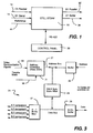
- a digital still store system 10 which receives composite digital 4:2:2 D1 signal inputs in parallel at 12 or serially at 14.
- a D1 signal defor- matter 16 separates the D1 signals into their luminance (Y) and chrominance (e IV and (C B ) components and supplies the signals in component form alternatively to framestores 18 and 20.
- the component signals are supplied from the framestores 18 and 20 to hard disks 22 through a buffer store 24 and disk input/output (I/O) circuits 26.
- the two framestores 18 and 20 are used for allowing real time wipe between two images and handling other situations involving two images.
- Each of the hard disks 22 has a capacity to store 100 still video images as either 525 or 625 line digital frames for either NTSC or PAL component signal inputs and outputs.
- Y, C R and C B fields of component video signal information are supplied from the hard disks 22 through the buffer store 24 to a framestore 18 or 20, to a compositor 28 for output as digital 4:2:2 video signals through a D1 formatter 30 at 32 and 34.
- the formatter 30 combines the component Y, C R and C B fields into frames of component video signals. Fields of component video information can also be supplied directly to the compositor 28 from the framestores 18 and 20.
- System operation is controlled by a central processing unit (CPU) 36, desirably implemented as a control oriented microprocessor, such as an NEC V40 microprocessor.
- CPU central processing unit
- User inputs are provided to the CPU 36 from a control panel 38 through a serial RS-422 communications link. Additional inputs to the CPU 36 can be provided at 40 and 42.
- the RS-422 input 42 can be used for extemal control of the system 10.
- This input 42 can be used to provide additional information about images for storage with the video image signals, such as a name for an image or a time code.
- a reference input at 44 is supplied to a synchronizing pulse generator 46.
- the CPU 36 runs a suitable system control program, stored in a read only memory (ROM), not shown.
- ROM read only memory
- the framestores 18 and 20 change addressing of the field video signals in one field time into the buffer store 24, which then writes the signals to one of the disks 22.
- the buffer store obtains the video signal fields for either full size images or 1/4 size images, when an array for browsing and selection is desired.
- the field video signals are obtained by addressing every fourth pixel of the field for readout.
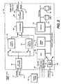
- FIG. 3 shows details of the buffer store 24.
- a 256 KByte static random access memory (RAM) 25 receives address inputs on address bus 27.
- the addresses are supplied from CPU 36 through buffer circuit 29 and from a Xilinx 3020 address generator integrated circuit 31 from video synchronization and transfer mode inputs at 33 and 35.
- Data is supplied to and from the RAM 25 by framestores 18 and 20 through a 4:1 bidirectional multiplexer 37. Data is also supplied to and from the RAM 25 by disks 22 through bidirectional buffer circuit 39.
- the buffer store 24 is a mechanism for interfacing information at fast (video) rates to slow (computer) rates. It is also used to modify the order that information passes through it to effect an apparent video image size reduction, but without the need for data processing.
- the buffer store 24 may perform one and only one of the following activities:
- Activities 1) and 2) above entail data access in a predetermined order, since the framestores 18 and 20 are sequential access.
- the address generator 31 may modify the sequence of addresses in order to store the information in a convenient way on the disk 22 such that, when a "browse" image is brought up, the individual, small 1/4 size pictures may be retrieved quickly.
- Tables 1 and 2 show the addresses for full size image Y and C field video signals as stored and the addresses for read out of 1/4 size images for NTSC and PAL video signal outputs.
- the sequence of addresses for modes 1)-2) is shown in Table 1.
- Mode 1) is on the left side
- Mode 2) on the right.
- Each cell in the table contains the address before modification at the bottom and the modified address at the top.
- the idea is to form, for each field of each component, 16 quadrants each of 22 blocks of 512 bytes (NTSC only). Each quadrant is a reduced-size version of the original.
- a quadrant accessed individually represents a 1/16 (areal) version of the original image. By putting all 16 quadrants together, the entire image is reconstituted without loss.
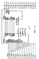
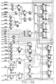
- the address generation and modification for transfers between the buffer store 24 and the framestores is encapsulated in the field-programmable logic array (FPLA) integrated circuit 31.
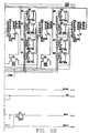
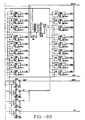
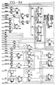
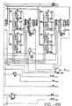
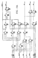
- Circuit schematics which comprise the effective circuitry programmed into the integrated circuit 31 for each of the 4 transfer modes are shown in Figures 4, 5A, 5B, 6A, 6B, 7, 8A, 8B, 9A, 9B and 9C.
- Figures 4 and 7 respectively show how figures 5A, 5B, 6A, 6B and Figures 8A, 8B, 9A, 9B and 9C are connected together.
- the combination of logic circuits shown in these figures produces the addresses shown in Tables 1 and 2.
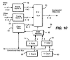
- the system 10 allows the use of various wipes, such as vertical, horizontal and rectangular wipes, to provide visual and electronic color comparison.
- Figure 10 shows the electronics of the compositor 28 for generating these wipes and for preparing other video image signal outputs from the system.
- the framestores 18 and 20 respectively provide A and B video signal outputs to a 3:1 multiplexer 50.
- Video signal information obtained from one of the disks 22 ( Figure 2) via the buffer store 24 is supplied to one of the framestores 18 or 20.
- a horizontal counter 58 and a vertical counter 60 are respectively connected to RAMs 54 and 56 to produce readout of the information to state machine 62.
- Information stored in the RAMs 54 and 56 determines the corners of the wipe rectangle.
- the output of the state machine 62 is supplied to the multiplexer 50.
- the compositor 28 thus functions as a memory addressing system to prepare the composited video output signals.
- Table 3 below is a source code listing for the state machine 62.
- Q0, Q1, Q2, Q3, Q4, Q5 pin 16, 18, 15, 19, 20, 21 ;
- H,L,Q,X 1,0,.C.,.X.;
- the total record time is 750 ms.
- the steps in playing back an image are exactly those as in recording, but executed in reverse, as shown in Figure 12.
- Total time is 250 ms.
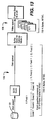
- Figure 14 shows a control panel 80 for the system 10.
- the front panel 80 includes a 20 character by 2 line display 82, a plurality of modal keys 84, a numeric keypad 86, enter key 88, and a trackball 90.
- the display 82 shows the current operating mode of the system 10, the last picture or item, the next picture or item, and general information for the operation of the system. The format shown below in Table 4 is used for the display 82.
- the modal keys 84 are used to select the mode of operation of the system 10. Each modal key 84 has an LED 85 to indicate when its mode is active.
- the numeric keypad 86 is for entry of numeric values, including picture numbers.
- the trackball 90 is for selecting pictures in the browse mode, for scrolling selections in system menus shown on the display 82, and for entering values when used in conjunction with the enter key 88. Operations of the system 10 are as follows:
- the current picture being shown by the still store system 10 is displayed as the last picture number.
- the next picture number shows the picture that will be displayed when enter is pushed.
- the enter key 88 is pushed, the next picture will be shown.
- the operator can at any time key in a new number that will be displayed in the next picture location on the display 82. If no picture is stored at the selected location, the information on the display 82 reads as shown in Table 6.
- enter key 88 If enter key 88 is then pressed, the system will search and play the next higher number having a stored picture.
- the 45 in Table 7 indicates the remaining picture slots. After selecting the record mode, a number is entered with the numeric keypad 86. When the enter key is pushed, the current picture being shown by the system is recorded on disk. Recording does not occur where a previous picture is recorded. If the selected location already has a picture recorded there, the display is as shown in Table 8.
- DELETE mode is selected by pressing the delete modal key 84.
- the display 82 is as shown in Table 10.
- the picture at the location keyed in is recalled from the disk 22 and placed in the store.
- the picture is erased from the disk. This allows a picture to be rerecorded at the same or different number. If no picture is found at the location keyed in, the display is as shown in Table 12.
- Range Delete is a modified form of delete.
- the system enters this mode when the To" key in the keypad 86 is used. After pressing the Delete modal key 84, the first picture of the range to be deleted is entered with the keypad 86. The To key is then pressed, and the display changes to the form shown in Table 13.
- the last number of the range is then entered with the keypad 86, followed by pressing the Enter key 88.
- the system responds with the display shown in Table 14.
- the Disk mode is accessed with the Disk modal key 84 and gives access to items associated with the disks 22. All items are accessed by scrolling through a list using the trackball 90. The trackball 90 is right/down to go lower on the list and left/up to go up the list. If a function requires data entry, then the keypad 86 is used. As an alternate, the enter key 88 is held down while the trackball 90 is used to enter a value. Functions accessed in this mode include selecting current drive, copying between fixed or cartridge media, space remaining and disk format.
- Setup mode is accessed with the Setup modal key 84 and gives access to items associated with setup of the system 10. All items are accessed by scrolling through a list using the trackball 90.
- the trackball 90 motion and data entry is the same as for the Disk mode.
- the setup items include:
- Grab mode is selected with the Grab modal key 84 to grab live video. This mode only works when the system 10 is in the Live store mode.
- Wipe modal keys 84 There are four wipe modes, respectively selected by the four Wipe modal keys 84 shown from left to right in the bottom row of modal keys. Selecting the wipe modes enables the operator to compare live video to store video or the video from two stores. Selecting wipes cancels the Browse, Disk, Setup and Delete modes. Selecting wipes does not change the appearance of any displays.
- Horizontal Wipe enables the trackball 90 to move the wipe in the left to right direction.
- Vertical Wipe enables the trackball to move the wipe in the top to bottom direction.
- Horizontal and Vertical Wipe can be on together.
- Box Wipe enables the trackball to move the box wipe anywhere on screen.
- Wipe Size enables the trackball to control the size of the wipe on screen.
- Compare mode is accessed with the Compare modal key 84 and allows the operator to compare the RGB values of any two locations on screen.
- the Compare modal key is pressed, the display 82 is as shown in Table 19.
- the trackball 90 now increments the lower RGB values. Pressing the Enter key 88 again returns the operator to the upper values.
- the computer determines which framestore 18 or 20 is holding the image being pointed at by the cursor on the screen. That image is copied into the buffer store 24. The computer then reads out the pixel color value at the address value corresponding to the pixel pointed at on the screen. To improve noise immunity, local averaging of the pixels is employed.
- the "Last" area on the display shows the current picture number in the store.
- the "Next” area shows the picture number that the cursor is on.
- the operator moves the cursor over the array of pictures on the screen with the trackball 90 and presses the Enter key 88 to select a picture.
- the system 10 then leaves the Browse mode, enters the Play mode, and the selected picture is recalled from the disk 22 on which it is stored. After the picture is played, it can be deleted by pressing Delete followed by the Enter key 88.
- the still store system and method does not require image data processing for display of reduced size images. It further does not require storage of images in both full size and reduced size in order to allow selective display of reduced size images.
- the still store system and method allows convenient visual and electronic color comparison of images.
- the control system of the still store system and method is easy to use.
Abstract
Description
- The present invention relates generally to an electronic system and method for storing and retrieving information representing a multiplicity of video image frames. More particularly, it relates to such a system and method in which a data processing operation is not required to store the video image frames and to retrieve them for display in either their full size or as a set of reduced-size images displayed together, such as for browsing and selection. Most especially, it relates to such a system and method providing visual and electronic color comparison and an easy to use control system.
- Systems called still stores for storing and retrieving a multiplicity of single frame still images to and from, for example, disk drives, are known in the art. For example, such systems are disclosed in Taylor et al., U.S. Patent 4,302,776, issued November 24, 1981 and Beaulier, U.S. Patent 4,821,121, issued April 11, 1989. In the use of such systems, it is common to browse through the stored images in order to select a particular image for further processing. When making such a selection, it is highly desirable to show a number, for example, sixteen of the images simultaneously to allow side-by-side comparison of them.
- In the still store as described by Taylor et al., when a user wants to change the size of stored full size images to allow their display as an array of reduced size images, an image processor must process the image data after retrieving it from disk storage to generate the reduced size images. Taylor et al. were able to reduce system complexity over prior still store systems in which the image processing was carried out in real video time by doing the image processing in non-real time. However, the necessity to carry out such image processing whenever simultaneous display of reduced size images was desired means that a substantial system complexity is still required.
- In the still store described by Beaulier, the need to carry out processing of the image data each time for simultaneous display of reduced size images is eliminated by carrying out the image processing for size reduction on each full size image prior to storing the full size image for the first time. The reduced and full size images are then stored together on the disk storage for later accessing. Another system in which both full size images and reduced size images are stored is disclosed in Belmares-Sarabia et al., U.S. Patent 4,763,186, issued August 9, 1988. However, this approach does not eliminate all image data processing for reduced size image display, and it also requires the storage of additional information on the disk.
- A still store system in accordance with this invention for storing and retrieving information representing a multiplicity of video image frames consists of a plurality of pixels having at least one framestore connected to a video image signal input At least one bulk video image signal store stores a plurality of video images. A buffer store is connected to supply video image signals between the at least one framestore and the at leat one bulk video image signal store. The buffer store is connected to receive the video image signals from the at least one framestore. The buffer store has an address control for selectively retrieving the video image signals for full-size video image frames by addressing sequential addresses and reduced-size images by addressing one of a given number of the plurality of pixels in the full-size video image frames, to provide output video signals selectively for the full-size video image frames and an array of the reduced-size images as an image frame.
- A method for storing still images in accordance with this invention consisting of a plurality of pixels includes receiving video image signals defining the video image frames in at least one framestore. The video image signals are stored in a bulk storage means. The video image signals are retrieved from the bulk storage means selectively as full-size video image frames by addressing sequential addresses and reduced-size images by addressing one of a given number of the plurality of pixels in the full-size video image frames. Output video signals are provided selectively for the full-size video image frames and for the reduced-size images as an image frame. r
- Embodiments of this invention can thus provide a still store system and method which does not require image data processing for display of reduced size images, and storage of images in both full size and reduced size in order to allow selective display of reduced size images.
- Embodiments of the invention can also provide a still store system and method allowing convenient visual color comparison of images, and convenient electronic color comparison of images.
- The invention provides a still store system and method with an easy to use control system.
- Examples of the invention will now be described with reference to the drawings, in which:-
- Figure 1 is a generalized block diagram of a still store system in accordance with one embodiment of the invention;
- Figure 2 is a more detailed block diagram of the still store system of Figure 1;
- Figure 3 is a more detailed block diagram of a portion of the still store system of Figures 1 and 2;
- Figures 4, 5A, 5B, 6A, 6B, 7, 8A, 8B, 9A and 9B are circuit schematic diagrams of another portion of the still store system of Figures 1 and 2.
- Figures 11, 12 and 13 are flow chart representations useful for understanding operation of the still store system of Figures 1 and 2.
- Figure 14 is a front view of the still store system of Figures 1-3, showing a front panel of the system.
- Turning now to the drawings, more particularly to Figures 1 and 2, there is shown a digital still
store system 10, which receives composite digital 4:2:2 D1 signal inputs in parallel at 12 or serially at 14. A D1 signal defor-matter 16 separates the D1 signals into their luminance (Y) and chrominance (eIV and (CB) components and supplies the signals in component form alternatively toframestores framestores hard disks 22 through abuffer store 24 and disk input/output (I/O)circuits 26. The twoframestores hard disks 22 has a capacity to store 100 still video images as either 525 or 625 line digital frames for either NTSC or PAL component signal inputs and outputs. - Y, CR and CB fields of component video signal information are supplied from the
hard disks 22 through thebuffer store 24 to aframestore compositor 28 for output as digital 4:2:2 video signals through aD1 formatter 30 at 32 and 34. Theformatter 30 combines the component Y, CR and CB fields into frames of component video signals. Fields of component video information can also be supplied directly to thecompositor 28 from theframestores - System operation is controlled by a central processing unit (CPU) 36, desirably implemented as a control oriented microprocessor, such as an NEC V40 microprocessor. User inputs are provided to the
CPU 36 from acontrol panel 38 through a serial RS-422 communications link. Additional inputs to theCPU 36 can be provided at 40 and 42. For example, the RS-422input 42 can be used for extemal control of thesystem 10. Thisinput 42 can be used to provide additional information about images for storage with the video image signals, such as a name for an image or a time code. A reference input at 44 is supplied to a synchronizingpulse generator 46. TheCPU 36 runs a suitable system control program, stored in a read only memory (ROM), not shown. - In operation, the
framestores buffer store 24, which then writes the signals to one of thedisks 22. For playback, the buffer store obtains the video signal fields for either full size images or 1/4 size images, when an array for browsing and selection is desired. When the 1/4 size images are desired, the field video signals are obtained by addressing every fourth pixel of the field for readout. - Figure 3 shows details of the
buffer store 24. A 256 KByte static random access memory (RAM) 25 receives address inputs onaddress bus 27. The addresses are supplied fromCPU 36 throughbuffer circuit 29 and from a Xilinx 3020 address generator integratedcircuit 31 from video synchronization and transfer mode inputs at 33 and 35. Data is supplied to and from theRAM 25 byframestores bidirectional multiplexer 37. Data is also supplied to and from theRAM 25 bydisks 22 throughbidirectional buffer circuit 39. - The
buffer store 24 is a mechanism for interfacing information at fast (video) rates to slow (computer) rates. It is also used to modify the order that information passes through it to effect an apparent video image size reduction, but without the need for data processing. - At any instant, the
buffer store 24 may perform one and only one of the following activities: - 1) transfer one field of one component from either
framestore buffer store 24. - 2) transfer one field of one component from the
buffer store 24 into eitherframestore - 3) transfer information to or from the
disks 22. - 4) nothing.
- Activities 1) and 2) above entail data access in a predetermined order, since the
framestores address generator 31 may modify the sequence of addresses in order to store the information in a convenient way on thedisk 22 such that, when a "browse" image is brought up, the individual, small 1/4 size pictures may be retrieved quickly. - There are four modes of address modification, one for each of the following tasks:
- 1) Transferring a full-size image, Y component, between the framestore 18 or 20 Y section and the
buffer store 24 in either direction. - 2) Same as 1), but for a C component.
- 3) Transferring 16 reduced-size "browse" images from the
buffer store 24 to theframestore - 4) "Linear" mode, without modification. Useful for transferring a full-size image to or form the
buffer store 24 so that theCPU 36 can easily access the information without having to cope with a "scrambled" version of the image. - Address mode 3) above differs between 525-line systems (NTSC) and 625-line systems (PAL). The other three modes are the same for both video standards.
- Tables 1 and 2 show the addresses for full size image Y and C field video signals as stored and the addresses for read out of 1/4 size images for NTSC and PAL video signal outputs. The sequence of addresses for modes 1)-2) is shown in Table 1. Mode 1) is on the left side, Mode 2) on the right. Each cell in the table contains the address before modification at the bottom and the modified address at the top. The idea is to form, for each field of each component, 16 quadrants each of 22 blocks of 512 bytes (NTSC only). Each quadrant is a reduced-size version of the original. A quadrant accessed individually represents a 1/16 (areal) version of the original image. By putting all 16 quadrants together, the entire image is reconstituted without loss.
- The sequence for mode 3) is shown in Table 2. It is similar in form. 525-line operation is at the left, 625-line at the right. The sequence for mode 4) is not shown because it is so simple; each cell in its table would contain identical top and bottom numbers.


- The address generation and modification for transfers between the
buffer store 24 and the framestores is encapsulated in the field-programmable logic array (FPLA) integratedcircuit 31. Circuit schematics which comprise the effective circuitry programmed into theintegrated circuit 31 for each of the 4 transfer modes are shown in Figures 4, 5A, 5B, 6A, 6B, 7, 8A, 8B, 9A, 9B and 9C. Figures 4 and 7 respectively show how figures 5A, 5B, 6A, 6B and Figures 8A, 8B, 9A, 9B and 9C are connected together. The combination of logic circuits shown in these figures produces the addresses shown in Tables 1 and 2. - The
system 10 allows the use of various wipes, such as vertical, horizontal and rectangular wipes, to provide visual and electronic color comparison. Figure 10 shows the electronics of thecompositor 28 for generating these wipes and for preparing other video image signal outputs from the system. Theframestores multiplexer 50. Video signal information obtained from one of the disks 22 (Figure 2) via thebuffer store 24 is supplied to one of theframestores horizontal counter 58 and avertical counter 60 are respectively connected toRAMs state machine 62. Information stored in theRAMs state machine 62 is supplied to themultiplexer 50. Thecompositor 28 thus functions as a memory addressing system to prepare the composited video output signals. Table 3 below is a source code listing for thestate machine 62. - MODULE fs_compositor
- flag '-r2'
- TITLE 'Field Store -- Composite Control
- fs_u179 device'P22V10';
-
CLK pin 1 ; - VAV, MRKTYPE,
VPO pin - VP1, HPO,
HP1 pin - HAV, COMPEN,
MARKEN pin - CBFEN,
ABACK pin - ABSWITCH,
BRDROE pin - Q0, Q1, Q2, Q3, Q4,
Q5 pin - MRKOE,
DATAOE pin 22, 23 ; - True, False = 1,0;
- High, Low = 1,0;
- H,L,Q,X = 1,0,.C.,.X.;
- "State Machine State Assignments

- "State Input Modesequations

- DATAOE := !(HAV * VAV * MRKOE * BRDROE ) ;


- Further details on the operation of the
system 10 in the record, playback and browse modes of operation are shown in Figures 11, 12 and 13. The record operation is shown in Figure 11. The steps in recording an image are as follows: - a) Capture (freeze) an image in either
framestore - b) Transfer the Y component,
field 1, to thebuffer store 24, as indicated at 102. This takes one field time = 15 milliseconds (ms.) in NTSC. The buffer store-24 address mode 1) is used. Theaddress generator 31 segments the image into 16 quadrants, each representing 1/16th of the entire image. - c)
Transfer quadrant 1 to thedisk 22, as indicated at 104. This quadrant becomes 22 512-byte blocks ondisk 22, recorded contiguously, and takes 10 ms. - d) Repeat c) above for the remaining 15 quadrants.
- To transfer all 16 quadrants takes 172 ms. in NTSC.
- e) Repeat steps b)-d) in succession for
Y field 2;C field 1; andC field 2. - The total record time is 750 ms. The steps in playing back an image are exactly those as in recording, but executed in reverse, as shown in Figure 12.
- The steps to create a browse image are shown in Figure 13 and are:
- a) Locate the upper-left browse picture on
disk 22. Transfer theY field 1 first quadrant into thebuffer store 24 into its first quadrant position, as indicated at 106. - b) Locate the picture immediately to its right on
disk 22. Transfer itsquadrant 1 into the buffer store's second quadrant position. - c) Repeat b) for the remaining 14 browse pictures.
- Total time is 250 ms.
- d) Transfer the now-
full buffer store 24 into eitherframestore Y field 1 component, as indicated at 108. This takes 16 ms. Useaddress mode 3. - e) Repeat steps a)-d) in succession for fields Y,
field 2;C field 1; andC field 2. Total transfer time is 1 second in NTSC. - Figure 14 shows a
control panel 80 for thesystem 10. Thefront panel 80 includes a 20 character by 2line display 82, a plurality ofmodal keys 84, anumeric keypad 86,enter key 88, and atrackball 90. Thedisplay 82 shows the current operating mode of thesystem 10, the last picture or item, the next picture or item, and general information for the operation of the system. The format shown below in Table 4 is used for thedisplay 82.
- The
modal keys 84 are used to select the mode of operation of thesystem 10. Each modal key 84 has anLED 85 to indicate when its mode is active. Thenumeric keypad 86 is for entry of numeric values, including picture numbers. Thetrackball 90 is for selecting pictures in the browse mode, for scrolling selections in system menus shown on thedisplay 82, and for entering values when used in conjunction with theenter key 88. Operations of thesystem 10 are as follows: - In the PLAY mode,
display 82 appears as shown in Table 5.
- The current picture being shown by the
still store system 10 is displayed as the last picture number. The next picture number shows the picture that will be displayed when enter is pushed. When theenter key 88 is pushed, the next picture will be shown. The operator can at any time key in a new number that will be displayed in the next picture location on thedisplay 82. If no picture is stored at the selected location, the information on thedisplay 82 reads as shown in Table 6.
- If
enter key 88 is then pressed, the system will search and play the next higher number having a stored picture. - In RECORD mode, the information on the
display 82 reads as shown in Table 7.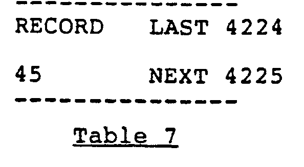
- The 45 in Table 7 indicates the remaining picture slots. After selecting the record mode, a number is entered with the
numeric keypad 86. When the enter key is pushed, the current picture being shown by the system is recorded on disk. Recording does not occur where a previous picture is recorded. If the selected location already has a picture recorded there, the display is as shown in Table 8.
- The system advances to the next higher number available. Pressing enter records the picture at the next higher number available. The display then appears as shown in Table 9.

- DELETE mode is selected by pressing the delete
modal key 84. Thedisplay 82 is as shown in Table 10.
- There is no "last" number shown on the display. The "next " number shows the picture currently in the store. When the
enter key 88 is pressed, the system will delete the picture currently in the store off thedisk 22 and the "next " number will advance to the next highest number, so that the display appears as shown in Table 11.
- When a new number is keyed in with the
keypad 86 and theenter key 88 is pushed, the picture at the location keyed in is recalled from thedisk 22 and placed in the store. The picture is erased from the disk. This allows a picture to be rerecorded at the same or different number. If no picture is found at the location keyed in, the display is as shown in Table 12.
- Range Delete is a modified form of delete. The system enters this mode when the To" key in the
keypad 86 is used. After pressing the Delete modal key 84, the first picture of the range to be deleted is entered with thekeypad 86. The To key is then pressed, and the display changes to the form shown in Table 13.
- The last number of the range is then entered with the
keypad 86, followed by pressing theEnter key 88. The system responds with the display shown in Table 14.
- Pressing enter again completes the range delete. In this mode, the system does not recall the pictures into the store, but simply erases them off the
disk 22. - The Disk mode is accessed with the Disk modal key 84 and gives access to items associated with the
disks 22. All items are accessed by scrolling through a list using thetrackball 90. Thetrackball 90 is right/down to go lower on the list and left/up to go up the list. If a function requires data entry, then thekeypad 86 is used. As an alternate, theenter key 88 is held down while thetrackball 90 is used to enter a value. Functions accessed in this mode include selecting current drive, copying between fixed or cartridge media, space remaining and disk format. - Setup mode is accessed with the Setup modal key 84 and gives access to items associated with setup of the
system 10. All items are accessed by scrolling through a list using thetrackball 90. Thetrackball 90 motion and data entry is the same as for the Disk mode. The setup items include: - 1. Recall setup, which brings back the contents of the setup menu previously stored in RAM. This provides for storage of 10 different setup configurations.
- 2. Record mode, in which the
Enter key 88 toggles between automatic record, as shown in Table 15.and grab and record, as shown in Table 16.

- Additional functions which toggle in the same manner with the
Enter key 88 include: - 3. Grab in field or frame mode.
- 4. Playback in field or frame mode.
- 5. Standard as 525 lines or 625 lines.
- 6. Machine Configuration, i.e., one
disk 22 for live video and the other for off disk video or both for off disk video. - 7. Sync Source, i.e., internal or external.
- 8. Input Select as serial or parallel.
- Other functions include:
- 9. Test Signals
- 10. Diagnostics
- 11. Timing, which allows selection of horizontal timing using the display shown in Table 17.

- 12. Dim Display
- 13. Dim Button LEDs Functions 12 and 13 allow brightness selection on a scale of 1 to 100.
- 14. Record Setup, which records the contents of the setup menu in RAM, using the display in Table 18.
- Grab mode is selected with the Grab modal key 84 to grab live video. This mode only works when the
system 10 is in the Live store mode. - There are four wipe modes, respectively selected by the four Wipe
modal keys 84 shown from left to right in the bottom row of modal keys. Selecting the wipe modes enables the operator to compare live video to store video or the video from two stores. Selecting wipes cancels the Browse, Disk, Setup and Delete modes. Selecting wipes does not change the appearance of any displays. Horizontal Wipe enables thetrackball 90 to move the wipe in the left to right direction. Vertical Wipe enables the trackball to move the wipe in the top to bottom direction. Horizontal and Vertical Wipe can be on together. Box Wipe enables the trackball to move the box wipe anywhere on screen. Wipe Size enables the trackball to control the size of the wipe on screen. - Compare mode is accessed with the Compare modal key 84 and allows the operator to compare the RGB values of any two locations on screen. When the Compare modal key is pressed, the
display 82 is as shown in Table 19.
- When the
trackball 90 moves, the display changes as shown in Table 20.
- The operator then moves the trackball to the first color in the image. The upper RGB values follow the cursor on the image. When the
Enter key 88 is pressed, the display appears as shown in Table 21.
- The
trackball 90 now increments the lower RGB values. Pressing theEnter key 88 again returns the operator to the upper values. - In order to do the electronic color comparison, the computer determines which framestore 18 or 20 is holding the image being pointed at by the cursor on the screen. That image is copied into the
buffer store 24. The computer then reads out the pixel color value at the address value corresponding to the pixel pointed at on the screen. To improve noise immunity, local averaging of the pixels is employed. - Browse mode is accessed with the
Browse modal key 84. When this key is pressed, thedisplay 82 appears as shown in Table 22.
- The "Last" area on the display shows the current picture number in the store. The "Next" area shows the picture number that the cursor is on. The operator moves the cursor over the array of pictures on the screen with the
trackball 90 and presses theEnter key 88 to select a picture. Thesystem 10 then leaves the Browse mode, enters the Play mode, and the selected picture is recalled from thedisk 22 on which it is stored. After the picture is played, it can be deleted by pressing Delete followed by theEnter key 88. - Attached hereto and forming a part of this application is an appendix consisting of source code and data files used in operation of the
system 10. - It should now be readily apparent to those skilled in the art that a still store system and method capable of achieving the stated objects of the invention has been provided. The still store system and method does not require image data processing for display of reduced size images. It further does not require storage of images in both full size and reduced size in order to allow selective display of reduced size images. The still store system and method allows convenient visual and electronic color comparison of images. The control system of the still store system and method is easy to use.
- It should further be apparent to those skilled in the art that various changes in form and details of the invention as shown and described may be made. It is intended that such changes be included within the spirit and scope of the claims appended hereto.
Claims (17)
Applications Claiming Priority (2)
| Application Number | Priority Date | Filing Date | Title |
|---|---|---|---|
| US50242190A | 1990-03-30 | 1990-03-30 | |
| US502421 | 1990-03-30 |
Publications (3)
| Publication Number | Publication Date |
|---|---|
| EP0449631A2 true EP0449631A2 (en) | 1991-10-02 |
| EP0449631A3 EP0449631A3 (en) | 1992-08-05 |
| EP0449631B1 EP0449631B1 (en) | 1996-01-03 |
Family
ID=23997748
Family Applications (1)
| Application Number | Title | Priority Date | Filing Date |
|---|---|---|---|
| EP91302744A Expired - Lifetime EP0449631B1 (en) | 1990-03-30 | 1991-03-28 | Still store system and method with simple image access |
Country Status (7)
| Country | Link |
|---|---|
| US (1) | US5451982A (en) |
| EP (1) | EP0449631B1 (en) |
| JP (1) | JPH0614290A (en) |
| AT (1) | ATE132679T1 (en) |
| CA (1) | CA2039492A1 (en) |
| DE (1) | DE69115965T2 (en) |
| ES (1) | ES2082134T3 (en) |
Families Citing this family (5)
| Publication number | Priority date | Publication date | Assignee | Title |
|---|---|---|---|---|
| JPH06276520A (en) * | 1993-03-22 | 1994-09-30 | Sony Corp | Picture processing unit |
| DE69319329T2 (en) * | 1993-05-19 | 1998-10-29 | Alsthom Cge Alcatel | Memory management method for a video server |
| US5581479A (en) * | 1993-10-15 | 1996-12-03 | Image Telecommunications Corp. | Information service control point, which uses different types of storage devices, which retrieves information as blocks of data, and which uses a trunk processor for transmitting information |
| US5544327A (en) * | 1994-03-01 | 1996-08-06 | International Business Machines Corporation | Load balancing in video-on-demand servers by allocating buffer to streams with successively larger buffer requirements until the buffer requirements of a stream can not be satisfied |
| JP4458714B2 (en) * | 2001-06-20 | 2010-04-28 | 富士通マイクロエレクトロニクス株式会社 | Image decoding apparatus, image decoding method, and program |
Citations (7)
| Publication number | Priority date | Publication date | Assignee | Title |
|---|---|---|---|---|
| EP0051228A2 (en) * | 1980-10-31 | 1982-05-12 | Kabushiki Kaisha Toshiba | Document information filing system |
| EP0157539A2 (en) * | 1984-03-31 | 1985-10-09 | Kabushiki Kaisha Toshiba | Electronic document filing system |
| EP0176290A1 (en) * | 1984-09-25 | 1986-04-02 | Sony Corporation | Video signal memories |
| JPS6378687A (en) * | 1986-09-22 | 1988-04-08 | Nippon Hoso Kyokai <Nhk> | Chrominance component correcting device |
| US4763208A (en) * | 1984-11-13 | 1988-08-09 | Nippon Kogaku K. K. | Playback apparatus in electronic still camera system |
| US4777525A (en) * | 1985-12-23 | 1988-10-11 | Preston Jr Kendall | Apparatus and method for a multi-resolution electro-optical imaging, display and storage/retrieval system |
| EP0310829A2 (en) * | 1987-09-14 | 1989-04-12 | Toppan Printing Co., Ltd. | Pre-print simulation apparatus |
Family Cites Families (3)
| Publication number | Priority date | Publication date | Assignee | Title |
|---|---|---|---|---|
| JPS60246429A (en) * | 1984-05-22 | 1985-12-06 | Nec Corp | Magnetostrictive plate for stabilizing relative magnetic field |
| GB8419291D0 (en) * | 1984-07-27 | 1984-08-30 | Micro Consultants Ltd | Image processing apparatus |
| JPS61118791A (en) * | 1984-11-15 | 1986-06-06 | 株式会社東芝 | Font compression apparatus |
-
1991
- 1991-03-28 DE DE69115965T patent/DE69115965T2/en not_active Expired - Fee Related
- 1991-03-28 CA CA002039492A patent/CA2039492A1/en not_active Abandoned
- 1991-03-28 ES ES91302744T patent/ES2082134T3/en not_active Expired - Lifetime
- 1991-03-28 EP EP91302744A patent/EP0449631B1/en not_active Expired - Lifetime
- 1991-03-28 AT AT91302744T patent/ATE132679T1/en active
- 1991-03-29 JP JP3133817A patent/JPH0614290A/en active Pending
-
1992
- 1992-06-23 US US07/902,753 patent/US5451982A/en not_active Expired - Lifetime
Patent Citations (7)
| Publication number | Priority date | Publication date | Assignee | Title |
|---|---|---|---|---|
| EP0051228A2 (en) * | 1980-10-31 | 1982-05-12 | Kabushiki Kaisha Toshiba | Document information filing system |
| EP0157539A2 (en) * | 1984-03-31 | 1985-10-09 | Kabushiki Kaisha Toshiba | Electronic document filing system |
| EP0176290A1 (en) * | 1984-09-25 | 1986-04-02 | Sony Corporation | Video signal memories |
| US4763208A (en) * | 1984-11-13 | 1988-08-09 | Nippon Kogaku K. K. | Playback apparatus in electronic still camera system |
| US4777525A (en) * | 1985-12-23 | 1988-10-11 | Preston Jr Kendall | Apparatus and method for a multi-resolution electro-optical imaging, display and storage/retrieval system |
| JPS6378687A (en) * | 1986-09-22 | 1988-04-08 | Nippon Hoso Kyokai <Nhk> | Chrominance component correcting device |
| EP0310829A2 (en) * | 1987-09-14 | 1989-04-12 | Toppan Printing Co., Ltd. | Pre-print simulation apparatus |
Non-Patent Citations (1)
| Title |
|---|
| PATENT ABSTRACTS OF JAPAN vol. 12, no. 314 (E-649)25 August 1988 & JP-A-63 078 687 ( NIPPON HOSO KYOKAI <NHK> ) 8 April 1988 * |
Also Published As
| Publication number | Publication date |
|---|---|
| EP0449631B1 (en) | 1996-01-03 |
| JPH0614290A (en) | 1994-01-21 |
| DE69115965D1 (en) | 1996-02-15 |
| ES2082134T3 (en) | 1996-03-16 |
| DE69115965T2 (en) | 1996-06-27 |
| EP0449631A3 (en) | 1992-08-05 |
| CA2039492A1 (en) | 1991-10-01 |
| ATE132679T1 (en) | 1996-01-15 |
| US5451982A (en) | 1995-09-19 |
Similar Documents
| Publication | Publication Date | Title |
|---|---|---|
| KR0148015B1 (en) | Pip television system | |
| EP0543414B1 (en) | Method and apparatus for controlling rapid display of multiple images from a digital image database | |
| US4821121A (en) | Electronic still store with high speed sorting and method of operation | |
| EP0454414A2 (en) | Video signal display | |
| WO2001080560A1 (en) | Multi-format video processing | |
| GB2266037A (en) | An electronic video processing system | |
| WO1992003816A1 (en) | A display control device incorporating an auxiliary display | |
| RU97100746A (en) | SCREEN INDICATION DEVICE FOR DIGITAL VIDEO PROCESSING SYSTEM | |
| JPH0771203B2 (en) | Signal recording device and signal processing device | |
| EP0599607B1 (en) | Video editing system | |
| JP2650186B2 (en) | Still image video signal processing device | |
| JP3300059B2 (en) | Image processing system | |
| JP2592124B2 (en) | Image retrieval device | |
| EP0449631B1 (en) | Still store system and method with simple image access | |
| US4941127A (en) | Method for operating semiconductor memory system in the storage and readout of video signal data | |
| EP0302843A2 (en) | Computer aided working station for the design and/or processing of sketches for articles of clothing | |
| JP2637821B2 (en) | Superimpose device | |
| JP2785203B2 (en) | Editing device | |
| EP0595556A1 (en) | A high resolution image processing system using low resolution subimages | |
| JPS63175583A (en) | Plural input picture edition recording system | |
| JPH01284973A (en) | Picture recording and reproducing device | |
| JPH0286451A (en) | Video printer | |
| CA1284214C (en) | Method for editing video still pictures | |
| JPH02284583A (en) | Information inserting device | |
| JPH02285879A (en) | Still picture filing device |
Legal Events
| Date | Code | Title | Description |
|---|---|---|---|
| PUAI | Public reference made under article 153(3) epc to a published international application that has entered the european phase |
Free format text: ORIGINAL CODE: 0009012 |
|
| AK | Designated contracting states |
Kind code of ref document: A2 Designated state(s): AT BE CH DE DK ES FR GB GR IT LI LU NL SE |
|
| RIN1 | Information on inventor provided before grant (corrected) |
Inventor name: SHEIKH, JUNAID Inventor name: GALLO, LUIGI Inventor name: STERN, JOHN Inventor name: GEORGE, DOUGLAS J. |
|
| PUAL | Search report despatched |
Free format text: ORIGINAL CODE: 0009013 |
|
| AK | Designated contracting states |
Kind code of ref document: A3 Designated state(s): AT BE CH DE DK ES FR GB GR IT LI LU NL SE |
|
| 17P | Request for examination filed |
Effective date: 19930112 |
|
| 17Q | First examination report despatched |
Effective date: 19950504 |
|
| GRAA | (expected) grant |
Free format text: ORIGINAL CODE: 0009210 |
|
| AK | Designated contracting states |
Kind code of ref document: B1 Designated state(s): AT BE CH DE DK ES FR GB GR IT LI LU NL SE |
|
| PG25 | Lapsed in a contracting state [announced via postgrant information from national office to epo] |
Ref country code: NL Free format text: LAPSE BECAUSE OF FAILURE TO SUBMIT A TRANSLATION OF THE DESCRIPTION OR TO PAY THE FEE WITHIN THE PRESCRIBED TIME-LIMIT Effective date: 19960103 Ref country code: DK Effective date: 19960103 Ref country code: LI Free format text: LAPSE BECAUSE OF FAILURE TO SUBMIT A TRANSLATION OF THE DESCRIPTION OR TO PAY THE FEE WITHIN THE PRESCRIBED TIME-LIMIT Effective date: 19960103 Ref country code: AT Effective date: 19960103 Ref country code: CH Free format text: LAPSE BECAUSE OF FAILURE TO SUBMIT A TRANSLATION OF THE DESCRIPTION OR TO PAY THE FEE WITHIN THE PRESCRIBED TIME-LIMIT Effective date: 19960103 Ref country code: GR Free format text: LAPSE BECAUSE OF FAILURE TO SUBMIT A TRANSLATION OF THE DESCRIPTION OR TO PAY THE FEE WITHIN THE PRESCRIBED TIME-LIMIT Effective date: 19960103 Ref country code: BE Effective date: 19960103 |
|
| REF | Corresponds to: |
Ref document number: 132679 Country of ref document: AT Date of ref document: 19960115 Kind code of ref document: T |
|
| ITF | It: translation for a ep patent filed |
Owner name: FUMERO BREVETTI S.N.C. |
|
| REF | Corresponds to: |
Ref document number: 69115965 Country of ref document: DE Date of ref document: 19960215 |
|
| PGFP | Annual fee paid to national office [announced via postgrant information from national office to epo] |
Ref country code: FR Payment date: 19960221 Year of fee payment: 6 |
|
| PGFP | Annual fee paid to national office [announced via postgrant information from national office to epo] |
Ref country code: DE Payment date: 19960223 Year of fee payment: 6 |
|
| PGFP | Annual fee paid to national office [announced via postgrant information from national office to epo] |
Ref country code: GB Payment date: 19960228 Year of fee payment: 6 |
|
| PGFP | Annual fee paid to national office [announced via postgrant information from national office to epo] |
Ref country code: ES Payment date: 19960315 Year of fee payment: 6 |
|
| REG | Reference to a national code |
Ref country code: ES Ref legal event code: FG2A Ref document number: 2082134 Country of ref document: ES Kind code of ref document: T3 |
|
| ET | Fr: translation filed | ||
| PG25 | Lapsed in a contracting state [announced via postgrant information from national office to epo] |
Ref country code: LU Free format text: LAPSE BECAUSE OF NON-PAYMENT OF DUE FEES Effective date: 19960331 |
|
| PG25 | Lapsed in a contracting state [announced via postgrant information from national office to epo] |
Ref country code: SE Effective date: 19960403 |
|
| NLV1 | Nl: lapsed or annulled due to failure to fulfill the requirements of art. 29p and 29m of the patents act | ||
| REG | Reference to a national code |
Ref country code: CH Ref legal event code: PL |
|
| PLBE | No opposition filed within time limit |
Free format text: ORIGINAL CODE: 0009261 |
|
| STAA | Information on the status of an ep patent application or granted ep patent |
Free format text: STATUS: NO OPPOSITION FILED WITHIN TIME LIMIT |
|
| 26N | No opposition filed | ||
| PG25 | Lapsed in a contracting state [announced via postgrant information from national office to epo] |
Ref country code: GB Effective date: 19970328 |
|
| PG25 | Lapsed in a contracting state [announced via postgrant information from national office to epo] |
Ref country code: ES Free format text: LAPSE BECAUSE OF NON-PAYMENT OF DUE FEES Effective date: 19970329 |
|
| GBPC | Gb: european patent ceased through non-payment of renewal fee |
Effective date: 19970328 |
|
| PG25 | Lapsed in a contracting state [announced via postgrant information from national office to epo] |
Ref country code: FR Free format text: LAPSE BECAUSE OF NON-PAYMENT OF DUE FEES Effective date: 19971128 |
|
| PG25 | Lapsed in a contracting state [announced via postgrant information from national office to epo] |
Ref country code: DE Effective date: 19971202 |
|
| REG | Reference to a national code |
Ref country code: FR Ref legal event code: ST |
|
| REG | Reference to a national code |
Ref country code: ES Ref legal event code: FD2A Effective date: 19990405 |
|
| PG25 | Lapsed in a contracting state [announced via postgrant information from national office to epo] |
Ref country code: IT Free format text: LAPSE BECAUSE OF NON-PAYMENT OF DUE FEES Effective date: 20050328 |
|
| PGFP | Annual fee paid to national office [announced via postgrant information from national office to epo] |
Ref country code: IT Payment date: 20070612 Year of fee payment: 17 |
|
| PGRI | Patent reinstated in contracting state [announced from national office to epo] |
Ref country code: IT Effective date: 20091201 |
|
| PGRI | Patent reinstated in contracting state [announced from national office to epo] |
Ref country code: IT Effective date: 20091201 |