EP0449687B1 - Control process of a self-piloted synchronous motor and device for using the same - Google Patents
Control process of a self-piloted synchronous motor and device for using the same Download PDFInfo
- Publication number
- EP0449687B1 EP0449687B1 EP19910400635 EP91400635A EP0449687B1 EP 0449687 B1 EP0449687 B1 EP 0449687B1 EP 19910400635 EP19910400635 EP 19910400635 EP 91400635 A EP91400635 A EP 91400635A EP 0449687 B1 EP0449687 B1 EP 0449687B1
- Authority
- EP
- European Patent Office
- Prior art keywords
- signal
- controlled
- zero crossing
- electromotive force
- winding
- Prior art date
- Legal status (The legal status is an assumption and is not a legal conclusion. Google has not performed a legal analysis and makes no representation as to the accuracy of the status listed.)
- Expired - Lifetime
Links
Images


Classifications
-
- H—ELECTRICITY
- H02—GENERATION; CONVERSION OR DISTRIBUTION OF ELECTRIC POWER
- H02P—CONTROL OR REGULATION OF ELECTRIC MOTORS, ELECTRIC GENERATORS OR DYNAMO-ELECTRIC CONVERTERS; CONTROLLING TRANSFORMERS, REACTORS OR CHOKE COILS
- H02P6/00—Arrangements for controlling synchronous motors or other dynamo-electric motors using electronic commutation dependent on the rotor position; Electronic commutators therefor
- H02P6/14—Electronic commutators
- H02P6/16—Circuit arrangements for detecting position
- H02P6/18—Circuit arrangements for detecting position without separate position detecting elements
- H02P6/182—Circuit arrangements for detecting position without separate position detecting elements using back-emf in windings
Definitions
- the present invention due to the collaboration of the Laboratory of Electrical Engineering and Industrial Electronics of Jardin relates to a self-piloting synchronous motor with permanent magnet rotor, powered by a DC voltage source with bidirectional supply of the stator windings.
- Such motors are used in particular in motor vehicles, for example to drive a fan, windshield wipers or even a window regulator.
- the three stator phase windings are supplied, in pulse width modulation at fixed frequency, via an inverter comprising semiconductor elements with controlled conduction and extinction.
- the signal taken at the terminals of a winding in order to detect the zero crossing of the induced electromotive force comprises numerous parasites due in particular to the voltages induced by the currents in the other phases; this signal taken therefore presents numerous zero crossings and it is necessary to be able to detect the "good" zero crossing of this sampled signal, that is to say the instant when the electromotive force effectively cancels out.
- the invention proposes to provide a method and a device for controlling a self-piloting synchronous motor of the type described above in which the true zero crossing of the induced electromotive force is detected and in which the phase shift of thirty degrees is obtained reliably and using the minimum of components.
- the method for controlling a self-piloting synchronous motor according to the invention is characterized in that the signal taken from the terminals of each phase winding of the stator is sampled with synchronization with the modulation frequency of the inverter, the device for This process is defined by the characteristics of claim 8.
- a masking is carried out of the periods during which said winding is supplied. Furthermore, a masking of the moments of stator permutation phase is also carried out; in this way, the voltage across a winding is only monitored during the useful period during which the zero crossing of the induced electromotive force occurs.
- the phase shift of the zero crossing signal is obtained by counting clock pulses in two counters, one of which receives the signal representative of the passage to zero and the other the reverse of this signal, the count divided by two of a counter being compared to the count of the other counter and vice versa.
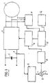
- FIG. 1 is a general block diagram of a self-piloting synchronous motor 1 which is supplied from a DC voltage source 2, for example a motor vehicle battery, via an inverter 3.
- the motor 1 comprises a permanent magnet rotor and a three-phase stator supplied by the inverter 3.
- the operation of this motor is regulated and for this purpose it comprises a current detector 4 associated with a current measurement device 5; the signal supplied by the circuit 5 is sent to a comparator 6 which also receives at 7 a current reference signal which is determined by the working conditions desired for the motor.
- the signal obtained is sent to a current control module 8, the output signal of which is sent to a pulse width modulator 9 which is controlled by a control module 10.
- the control module 10 receives in particular signals representative of zero crossings phase shifted by thirty degrees; these signals are produced by a module 11 which is the subject of the present invention and which is connected in particular to the terminals of the phase windings of the stator.
- the modulator 9 generates the control signals of the semiconductor elements of the inverter 3 from a sawtooth modulation signal at fixed frequency, the width being a function of the setpoint signal supplied by the module 8.
- a module 12 prepares special signals for starting the engine which are sent to the control module 10.
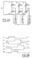
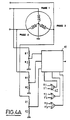
- FIG. 2A schematically represents the inverter 3 which supplies the three phase windings e1, e2 and e3 of the stator in a bidirectional manner.
- the inverter has six semiconductor elements with controlled conduction and extinction T1, T2, T3, T′1, T′2 and T′3 on each of which is connected in parallel a freewheeling diode 20 whose direction of direct conduction is opposite to the direction of direct conduction of the controlled semiconductor element.
- These controlled semiconductor elements can for example be bipolar transistors or MOS type transistors.
- the widths of the control periods of each of the semiconductors controlled each correspond to 120 electrical degrees and it can be seen that the period during which the electromotive force induced in a phase must be monitored is a period extending over sixty electrical degrees separating the control period of a semiconductor, T1 for example and the control period of the associated semiconductor, T′1.
- the offset between a zero crossing of the induced electromotive force and the next control of a semiconductor element of the inverter is thirty electrical degrees. It is therefore necessary to make a phase shift of this value in order to obtain, from the signal representative of the zero crossing of the electromotive force, the control signals of the semiconductor elements.
- the periods of 60 electrical degrees during which it is necessary to detect the zero crossing of the electromotive force of a winding correspond to periods when none of the semiconductor elements associated with the phase considered is controlled.
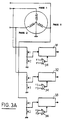
- FIG. 3A represents a circuit which makes it possible to eliminate for each of the windings the periods during which said winding is supplied in one direction or another.
- the voltage across each winding is taken and sent to a divider bridge made up of two resistors R1 and R2 for each winding.
- the voltage taken from the divider bridge is sent to an analog switch 31, respectively 32 or 33, each switch is controlled by a NOR logic gate having two inputs each receiving the control voltage of a controlled semiconductor T1, respectively T2 or T3, and of the associated controlled semiconductor T′1, respectively T′2 or T′3.
- the circuit of FIG. 3A therefore masks the periods during which the winding whose voltage is monitored is supplied by the inverter.
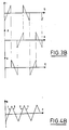
- FIG. 4A represents an alternative embodiment in which a global signal S is produced, the frequency of which is three times the frequency of the signal for the passage to zero of the electromotive force induced by a winding. Indeed, as can be seen in FIG. 3B, if we add the three signals of each of the phases, we obtain the continuous signal S of FIG. 4B.
- an analog switch 41 which has three inputs each controlled separately and a single output. Each input is controlled by a NOR logic gate 42 analogous to the gates 34 of FIG. 3A.
- FIG. 5 is a curve showing the detail of the voltage across a non-powered winding, the curve below representing the control signal of the transistors. It can be seen that the voltage across the winding is disturbed by the voltages induced, at the modulation frequency, by the switching of the semiconductors relating to the other phases. It is therefore necessary to provide a filtering of the signal observed at the terminals of each winding. This filtering consists in taking from this signal only the portions corresponding to the conductions of the transistors. In addition to avoid capturing the oscillations that appear on these portions at each switching, this sampling is carried out through a window of adequate width.
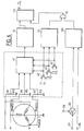
- FIG 6 is a block diagram of the module 11 of Figure 1 which provides a signal representative of the zero crossing of the electromotive force induced in each of the windings when the other two are powered. This figure shows the analog switch with three inputs 41 and the NOR logic gates 42.
- the global signal S supplied by the analog switch 41 is sent to an operational amplifier 51 which is mounted as a comparator with respect to ground; it makes it possible to detect the positive or negative value of the signal S and thus to supply a logic level at its output which is sent to a flip-flop of the D 52 type which constitutes a memory element and is driven by sampling pulses.
- the output signals of the NOR logic circuits 42 are also sent on a circuit 53 which makes it possible to mask the moments of phase permutation of the stator.
- the output of this circuit 53 is sent to an AND logic gate 54, the other input of which receives sampling pulses supplied by a circuit 55 which compares, on the one hand the sawtooth modulation signal which is applied at 56 and, on the other hand, the control signal 57 produced by the circuit 8 of FIG. 1.
- This circuit 55 is also controlled by the control signal produced by the circuit 8 of FIG. 1.
- control signal applied at 57 is added with a continuous component applied at 58 thanks to an adder 59.
- FIG. 7 respectively represents the curves of the global signal S, the sampling pulses and the signal supplied by the D type flip-flop 52 which is controlled by the sampling pulses supplied via the logic gate 54.
- the signal obtained is a rectangular signal whose each change of state corresponds to the passage through zero of the electromotive force induced in each of the windings; when this signal is at the high level, the electromotive force observed is positive and when the signal is at the low level, this electromotive force is negative.
- Each slot corresponds to a width of 60 electrical degrees.
- FIGS. 8 and 9 illustrate the embodiment of the phase shift of 30 electrical degrees, which uses two counters, one receiving the direct output signal from the flip-flop 52 and the other the inverse signal from the latter.
- the levels of the counters have been shown in an analog manner for reasons of clarification.
- the content of the first counter divided by two is compared with the content of the second counter and vice versa.
- the various curves successively represent the direct output signal S of flip-flop 52, the counting state of the first counter, this counting state divided by two, the counting state of the second counter, this counting state divided by two, the pulses corresponding to an equality for one of these count value pairs and finally the output signal which is phase shifted by half the width of the pulses of the overall signal, that is to say 30 degrees.
- the counting level of the first counter arrives at the counting level of the second counter divided by two; this results in a pulse 11 which corresponds to the rising edge of the phase shifted signal.
- the counting level of the second counter reaches the level of half the counting of the first counter and this results in the formation of a pulse 12 which corresponds to the falling edge of the phase shifted signal.
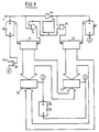
- Figure 9 is the block diagram of a device providing such a phase shift.
- a clock 70 of fixed frequency supplies clock pulses to two counters 71 and 72.
- the transmission of these clock signals to the counter 71 is controlled by the output signal S of the flip-flop 52 via a gate AND 73; with regard to the counter 72, the sending of the clock pulses is controlled by a signal opposite to the output signal of the flip-flop 52, the inversion being carried out by means of an inverter 74.
- the control of the transmission of the clock pulses are carried out via an AND circuit 75.
- the output word from each of the counters 71 and 72 which corresponds to the counting level is sent to a comparator 76, respectively 77.
- Each of these comparators also receives the value half of the output word from the other counter; that is to say that the comparator 76 compares the output word of counter 71 with the output half word of counter 72 and comparator 77 compares the output word of second counter 72 with the output half word of first counter 71.
- the signals C and D obtained at the output of the two comparators 76 and 77 control in opposite manner a flip-flop 78 whose output Q provides the signal phase shifted at 30 degrees.
- each counter a reset device constituted by a flip-flop 79, respectively 80, which is controlled by the output signal from the comparators 77 respectively 76.
- the output signal from the comparator 77 is sent to the flip-flop 79 by the through an OR gate 81 which receives an external reset signal at its other input.
- the invention makes it possible to perform efficient filtering of the parasitic signals of the electromotive force induced from each winding by means of the sampling process; this process has a high reliability and it does not introduce phase shift as would a conventional filter circuit.
- the realization of the phase shift of 30 degrees necessary to obtain the control signals of the semiconductor elements of the inverter is also obtained in a reliable and inexpensive manner thanks to the use of counters.
- the recommended solution minimizes phase difference errors during periods of motor acceleration.
- the frequency of the clock 70 is chosen so as to obtain a number of logical increments, at the level of the counters, which is sufficient for the maximum speed of the machine. So you can choose a frequency of 15 kHz; indeed, for a speed of 1000 rpm, 60 electrical degrees then correspond to 2.5 ms, which gives approximately 40 logical increments for 60 degrees.
- the logical value "1" is imposed on the first counter and the value "0" on the second.
- the reset carried out by the first comparator 76 is inhibited by using the signal C and the signal D is used to inhibit the reset made by the comparator 77.
Description
La présente invention due à la collaboration du Laboratoire d'Electrotechnique et d'Electronique Industrielle de Toulouse concerne un moteur synchrone autopiloté à rotor à aimants permanents, alimenté par une source de tension continue avec alimentation bidirectionnelle des enroulements du stator. De tels moteurs sont utilisés en particulier dans les véhicules automobiles, par exemple pour entraîner un ventilateur, des essuie-glaces ou encore un lève-vitre.The present invention due to the collaboration of the Laboratory of Electrical Engineering and Industrial Electronics of Toulouse relates to a self-piloting synchronous motor with permanent magnet rotor, powered by a DC voltage source with bidirectional supply of the stator windings. Such motors are used in particular in motor vehicles, for example to drive a fan, windshield wipers or even a window regulator.
Les trois enroulements de phase du stator sont alimentés, en modulation de largeur d'impulsion à fréquence fixe, par l'intermédiaire d'un onduleur comprenant des éléments semiconducteurs à conduction et extinction commandées.The three stator phase windings are supplied, in pulse width modulation at fixed frequency, via an inverter comprising semiconductor elements with controlled conduction and extinction.
Pour engendrer les signaux de commande des éléments semiconducteurs à vitesse variable, donc à fréquence variable, il faut détecter la position du rotor par rapport aux enroulements du stator.To generate the control signals of the semiconductor elements at variable speed, therefore at variable frequency, it is necessary to detect the position of the rotor with respect to the stator windings.
Dans le cas d'un moteur triphasé et avec la commande envisagée, il y a toujours une phase qui n'est pas alimentée pendant que les deux autres le sont et il est connu de détecter la position du rotor en détectant le passage par zéro de la force électromotrice induite dans l'enroulement non alimenté.In the case of a three-phase motor and with the envisaged control, there is always a phase which is not supplied while the other two are and it is known to detect the position of the rotor by detecting the passage through zero of the electromotive force induced in the non-powered winding.
Afin d'obtenir un fonctionnement au couple maximal pour un courant donné, il est nécessaire de déphaser les signaux de commande de l'onduleur d'un déphasage de 30 degrés par rapport à l'instant de passage à zéro de la force électromotrice induite dans l'enroulement non alimenté.In order to obtain operation at maximum torque for a given current, it is necessary to phase-shift the control signals of the inverter by a phase difference of 30 degrees from the instant of zero crossing of the electromotive force induced in the winding not supplied.
Le signal prélevé aux bornes d'un enroulement en vue de détecter le passage à zéro de la force électromotrice induite comporte de nombreux parasites dûs en particulier aux tensions induites par les courants dans les autres phases ; ce signal prélevé présente donc de nombreux passages à zéro et il faut pouvoir détecter le "bon" passage à zéro de ce signal prélevé, c'est-à-dire l'instant où la force électromotrice s'annule effectivement.The signal taken at the terminals of a winding in order to detect the zero crossing of the induced electromotive force comprises numerous parasites due in particular to the voltages induced by the currents in the other phases; this signal taken therefore presents numerous zero crossings and it is necessary to be able to detect the "good" zero crossing of this sampled signal, that is to say the instant when the electromotive force effectively cancels out.
Un tel procédé et dispositif sont connus de l'art anterieur EP-A- 231 046, qui, toutefois, ne mentionne pas de modulation de largeur d'impulsion.Such a method and device are known in the prior art EP-A-231 046, which, however, does not mention modulation of pulse width.
Il faut ensuite réaliser de manière fiable et peu coûteuse le déphasage de trente degrés du signal obtenu, cela pour une gamme de vitesses étendue.It is then necessary to carry out in a reliable and inexpensive manner the phase shift of thirty degrees of the signal obtained, this for a wide range of speeds.
L'invention se propose de réaliser un procédé et un dispositif de commande d'un moteur synchrone autopiloté du type décrit ci-dessus dans lequel on détecte de manière sûre le vrai passage à zéro de la force électromotrice induite et dans lequel le déphasage de trente degrés est obtenu de manière fiable et en utilisant le minimum de composants.The invention proposes to provide a method and a device for controlling a self-piloting synchronous motor of the type described above in which the true zero crossing of the induced electromotive force is detected and in which the phase shift of thirty degrees is obtained reliably and using the minimum of components.
Le procédé de commande d'un moteur synchrone autopiloté selon l'invention est caractérisé en ce que le signal prélevé aux bornes de chaque enroulement de phase du stator est échantillonné avec synchronisation avec la fréquence de modulation de l'onduleur, le dispositif pour mettre en oeuvre ce procédé est defini par les caracteristiques de la revendication 8.The method for controlling a self-piloting synchronous motor according to the invention is characterized in that the signal taken from the terminals of each phase winding of the stator is sampled with synchronization with the modulation frequency of the inverter, the device for This process is defined by the characteristics of
De cette manière, on réalise le filtrage des tensions induites parasites dûes aux commutations des éléments semiconducteurs reliés aux autres phases.In this way, the parasitic induced voltages due to the switching of the semiconductor elements connected to the other phases are filtered.
Selon une variante de l'invention, pour la détection du passage à zéro de la force électromotrice induite d'un enroulement, on réalise un masquage des périodes pendant lesquelles ledit enroulement est alimenté. Par ailleurs, on réalise également un masquage des instants de permutation de phase du stator; de cette manière, on ne surveille la tension aux bornes d'un enroulement que pendant la période utile pendant laquelle se produit le passage à zéro de la force électromotrice induite.According to a variant of the invention, for the detection of the passage to zero of the electromotive force induced by a winding, a masking is carried out of the periods during which said winding is supplied. Furthermore, a masking of the moments of stator permutation phase is also carried out; in this way, the voltage across a winding is only monitored during the useful period during which the zero crossing of the induced electromotive force occurs.
Le déphasage du signal du passage à zéro est obtenu par comptage d'impulsions d'horloge dans deux compteurs dont l'un reçoit le signal représentatif du passage à zéro et l'autre l'inverse de ce signal, le comptage divisé par deux d'un compteur étant comparé au comptage de l'autre compteur et inversement.The phase shift of the zero crossing signal is obtained by counting clock pulses in two counters, one of which receives the signal representative of the passage to zero and the other the reverse of this signal, the count divided by two of a counter being compared to the count of the other counter and vice versa.
L'utilisation de deux compteurs permet d'obtenir un déphasage de trente degrés dans une large gamme de vitesses.The use of two counters makes it possible to obtain a phase shift of thirty degrees in a wide range of speeds.
D'autres caractéristiques et avantages de l'invention ressortiront de la description qui suit d'un exemple de réalisation, faite en se référant aux dessins annexés sur lesquels :
- la figure 1 est un schéma général du circuit d'alimentation d'un moteur synchrone autopiloté ;
- les figures 2A et 2B représentent schématiquement une alimentation triphasée bidirectionnelle par onduleur et les périodes de commande des semiconducteurs de celui-ci ;
- les figures 3A et 3B illustrent le dispositif de masquage des périodes pendant lesquelles les enroulements sont alimentés ;
- les figures 4A et 4B illustrent un dispositif de masquage du même type dans lequel on obtient un signal unique ;
- la figure 5 est un diagramme montrant un détail de la tension prélevée aux bornes d'un enroulement non alimenté ;
- la figure 6 est un schéma synoptique du dispositif de détection du passage à zéro de la force électromotrice induite ;
- la figure 7 est un diagramme explicatif du schéma de la figure 6 ;
- la figure 8 est un diagramme de fonctionnement d'un déphaseur comportant deux compteurs ; et
- la figure 9 est un schéma synoptique du déphaseur à deux compteurs.
- Figure 1 is a general diagram of the power supply circuit of a self-piloting synchronous motor;
- FIGS. 2A and 2B schematically represent a bidirectional three-phase power supply by inverter and the control periods of the semiconductors thereof;
- FIGS. 3A and 3B illustrate the device for masking the periods during which the windings are supplied;
- FIGS. 4A and 4B illustrate a masking device of the same type in which a single signal is obtained;
- Figure 5 is a diagram showing a detail of the voltage drawn across a non-powered winding;
- FIG. 6 is a block diagram of the device for detecting the zero crossing of the induced electromotive force;
- Figure 7 is an explanatory diagram of the diagram of Figure 6;
- FIG. 8 is an operating diagram of a phase shifter comprising two counters; and
- Figure 9 is a block diagram of the two-meter phase shifter.
La figure 1 est un schéma synoptique général d'un moteur synchrone autopiloté 1 qui est alimenté à partir d'une source de tension continue 2, par exemple une batterie de véhicule automobile, par l'intermédiaire d'un onduleur 3. Le moteur 1 comporte un rotor à aimants permanents et un stator triphasé alimenté par l'onduleur 3. Le fonctionnement de ce moteur est régulé et il comporte à cet effet un détecteur de courant 4 associé à un dispositif de mesure du courant 5 ; le signal fourni par le circuit 5 est envoyé sur un comparateur 6 qui reçoit par ailleurs en 7 un signal de référence de courant qui est déterminé par les conditions de travail désirées pour le moteur. Le signal obtenu est envoyé sur un module de contrôle de courant 8 dont le signal de sortie est envoyé sur un modulateur de largeur d'impulsions 9 qui est commandé par un module de commande 10.FIG. 1 is a general block diagram of a self-piloting
Le module de commande 10 reçoit en particulier des signaux représentatifs des passages à zéro déphasés de trente degrés ; ces signaux sont élaborés par un module 11 qui fait l'objet de la présente invention et qui est branché en particulier sur les bornes des enroulements de phase du stator. Le modulateur 9 élabore les signaux de commande des éléments semiconducteurs de l'onduleur 3 à partir d'un signal de modulation en dents de scie à fréquence fixe, la largeur étant fonction du signal de consigne fourni par le module 8.The
Enfin, un module 12 élabore des signaux spéciaux pour le démarrage du moteur qui sont envoyés au module de commande 10.Finally, a
La figure 2A représente de manière schématique l'onduleur 3 qui alimente les trois enroulements de phase e1, e2 et e3 du stator de manière bidirectionnelle. L'onduleur comporte six éléments semiconducteurs à conduction et extinction commandées T1, T2, T3, T′1, T′2 et T′3 sur chacun desquels est branchée en parallèle une diode de roue libre 20 dont le sens de conduction directe est opposé au sens de conduction direct de l'élément semiconducteur commandé. Ces éléments semiconducteurs commandés peuvent par exemple être des transistors bipolaires ou des transistors de type MOS.FIG. 2A schematically represents the
Sur le diagramme 2B, on a représenté les périodes de commande de conduction de chacun des semiconducteurs de l'onduleur.In diagram 2B, the conduction control periods of each of the semiconductors of the inverter are shown.
Les largeurs des périodes de commande de chacun des semiconducteurs commandés correspondent chacune à 120 degrés électriques et on s'aperçoit que la période pendant laquelle on doit surveiller la force électro- motrice induite dans une phase est une période s'étendant sur soixante degrés électriques séparant la période de commande d'un semiconducteur, T1 par exemple et la période de commande du semiconducteur associé, T′1.The widths of the control periods of each of the semiconductors controlled each correspond to 120 electrical degrees and it can be seen that the period during which the electromotive force induced in a phase must be monitored is a period extending over sixty electrical degrees separating the control period of a semiconductor, T1 for example and the control period of the associated semiconductor, T′1.
On peut également constater que le décalage entre un passage à zéro de la force électromotrice induite et la commande suivante d'un élément semiconducteur de l'onduleur est de trente degrés électriques. Il est donc nécessaire de réaliser un déphasage de cette valeur pour obtenir, à partir du signal représentatif du passage à zéro de la force électromotrice, les signaux de commande des éléments semiconducteurs.It can also be seen that the offset between a zero crossing of the induced electromotive force and the next control of a semiconductor element of the inverter is thirty electrical degrees. It is therefore necessary to make a phase shift of this value in order to obtain, from the signal representative of the zero crossing of the electromotive force, the control signals of the semiconductor elements.
On a constaté plus haut que les périodes de 60 degrés électriques pendant lesquelles il faut détecter le passage à zéro de la force électromotrice d'un enroulement correspondent à des périodes où aucun des éléments semiconducteurs associés à la phase considérée n'est commandé.It was noted above that the periods of 60 electrical degrees during which it is necessary to detect the zero crossing of the electromotive force of a winding correspond to periods when none of the semiconductor elements associated with the phase considered is controlled.
La figure 3A représente un circuit qui permet d'éliminer pour chacun des enroulements les périodes pendant lesquelles ledit enroulement est alimenté dans un sens ou dans un autre. La tension aux bornes de chaque enroulement est prélevée et envoyée sur un pont diviseur constitué de deux résistances R1 et R2 pour chaque enroulement. La tension prélevée sur le pont diviseur est envoyée sur un interrupteur analogique 31, respectivement 32 ou 33, chaque interrupteur est commandé par une porte logique NON-OU comportant deux entrées recevant chacune la tension de commande d'un semiconducteur commandé T1, respectivement T2 ou T3, et du semiconducteur commandé associé T′1, respectivement T′2 ou T′3.FIG. 3A represents a circuit which makes it possible to eliminate for each of the windings the periods during which said winding is supplied in one direction or another. The voltage across each winding is taken and sent to a divider bridge made up of two resistors R1 and R2 for each winding. The voltage taken from the divider bridge is sent to an
De cette manière, on trouve à la sortie des interrupteurs commandés 31, 32, 33 un signal symétrique qui correspond à la tension aux bornes de la phase considérée pendant 60 degrés électriques de part et d'autre du point de passage à zéro de la force électromotrice induite. Ainsi, on trouve sur le diagramme de la figure 3B les trois signaux fournis respectivement par les interrupteurs 31, 32 et 33.In this way, there is at the output of the controlled
Le circuit de la figure 3A réalise donc un masquage des périodes pendant lesquelles l'enroulement dont on surveille la tension est alimenté par l'onduleur.The circuit of FIG. 3A therefore masks the periods during which the winding whose voltage is monitored is supplied by the inverter.
La figure 4A représente une variante de réalisation dans laquelle on élabore un signal global S dont la fréquence est le triple de la fréquence du signal de passage à zéro de la force électromotrice induite d'un enroulement. En effet, comme on peut le voir sur la figure 3B, si l'on ajoute les trois signaux de chacune des phases, on obtient le signal continu S de la figure 4B.FIG. 4A represents an alternative embodiment in which a global signal S is produced, the frequency of which is three times the frequency of the signal for the passage to zero of the electromotive force induced by a winding. Indeed, as can be seen in FIG. 3B, if we add the three signals of each of the phases, we obtain the continuous signal S of FIG. 4B.
Dans ce mode de réalisation, on utilise un interrupteur analogique 41 qui comporte trois entrées commandées chacune séparément et une seule sortie. Chaque entrée est commandée par une porte logique NON-OU 42 analogue aux portes 34 de la figure 3A.In this embodiment, an
La figure 5 est une courbe montrant le détail de la tension aux bornes d'un enroulement non alimenté, la courbe du dessous représentant le signal de commande des transistors. On constate que la tension aux bornes de l'enroulement est perturbée par les tensions induites, à la fréquence de modulation, par les commutations des semiconducteurs relatifs aux autres phases. Il faut donc prévoir un filtrage du signal observé aux bornes de chaque enroulement. Ce filtrage consiste à ne prélever sur ce signal que les portions correspondant aux conductions des transistors. De plus pour éviter de capter les oscillations qui apparaissent sur ces portions à chaque commutation, on réalise ce prélèvement à travers une fenêtre de largeur adéquate.FIG. 5 is a curve showing the detail of the voltage across a non-powered winding, the curve below representing the control signal of the transistors. It can be seen that the voltage across the winding is disturbed by the voltages induced, at the modulation frequency, by the switching of the semiconductors relating to the other phases. It is therefore necessary to provide a filtering of the signal observed at the terminals of each winding. This filtering consists in taking from this signal only the portions corresponding to the conductions of the transistors. In addition to avoid capturing the oscillations that appear on these portions at each switching, this sampling is carried out through a window of adequate width.
La figure 6 est un schéma synoptique du module 11 de la figure 1 qui fournit un signal représentatif du passage à zéro de la force électromotrice induite dans chacun des enroulements lorsque les deux autres sont alimentés. On retrouve sur cette figure l'interrupteur analogique à trois entrées 41 et les portes logiques NON-OU 42.Figure 6 is a block diagram of the
Le signal global S fourni par l'interrupteur analogique 41 est envoyé sur un amplificateur opérationnel 51 qui est monté en comparateur par rapport à la masse ; il permet de détecter la valeur positive ou négative du signal S et de fournir ainsi un niveau logique à sa sortie qui est envoyé sur une bascule de type D 52 qui constitue un élément de mémoire et est pilotée par des impulsions d'échantillonnage.The global signal S supplied by the
Les signaux de sortie des circuits logiques NON-OU 42 sont également envoyés sur un circuit 53 qui permet de réaliser le masquage des instants de permutation de phase du stator. La sortie de ce circuit 53 est envoyée sur une porte logique ET 54 dont l'autre entrée reçoit des impulsions d'échantillonnage fournies par un circuit 55 qui compare, d'une part le signal de modulation en dents de scie qui est appliqué en 56 et, d'autre part, le signal de commande 57 élaboré par le circuit 8 de la figure 1. Ce circuit 55 est également commandé par le signal de commande élaboré par le circuit 8 de la figure 1.The output signals of the NOR
Pour déterminer une fenêtre de capture dont la largeur soit inférieure à la période de commande des transistors, on additionne le signal de commande appliqué en 57 avec une composante continue appliquée en 58 grâce à un sommateur 59.To determine a capture window whose width is less than the control period of the transistors, the control signal applied at 57 is added with a continuous component applied at 58 thanks to an
La figure 7 représente respectivement les courbes du signal global S, les impulsions d'échantillonnage et le signal fourni par la bascule de type D 52 qui est commandée par les impulsions d'échantillonnage fournies par l'intermédiaire de la porte logique 54. On voit que le signal obtenu est un signal rectangulaire dont chaque changement d'état correspond au passage par zéro de la force électromotrice induite dans chacun des enroulements ; lorsque ce signal est au niveau haut, la force électromotrice observée est positive et lorsque le signal est au niveau bas, cette force électromotrice est négative. Chaque créneau correspond à une largeur de 60 degrés électriques.FIG. 7 respectively represents the curves of the global signal S, the sampling pulses and the signal supplied by the D type flip-
Les figures 8 et 9 illustrent le mode de réalisation du déphasage de 30 degrés électriques, qui utilise deux compteurs recevant l'un le signal direct de sortie de la bascule 52 et l'autre le signal inverse de ce dernier.FIGS. 8 and 9 illustrate the embodiment of the phase shift of 30 electrical degrees, which uses two counters, one receiving the direct output signal from the flip-
Sur le diagramme de la figure 8, les niveaux des compteurs ont été représentés de manière analogique pour des raisons de clarification. Conformément à l'invention, on compare le contenu du premier compteur divisé par deux avec le contenu du deuxième compteur et inversement.In the diagram in FIG. 8, the levels of the counters have been shown in an analog manner for reasons of clarification. According to the invention, the content of the first counter divided by two is compared with the content of the second counter and vice versa.
Sur la figure 8, les différentes courbes représentent successivement le signal direct de sortie S de la bascule 52, l'état de comptage du premier compteur, cet état de comptage divisé par deux, l'état de comptage du deuxième compteur, cet état de comptage divisé par deux, les impulsions correspondant à une égalité pour l'un de ces couples de valeur de comptage et enfin le signal de sortie qui est déphasé d'une moitié de la largeur des impulsions du signal global, c'est-à-dire 30 degrés.In FIG. 8, the various curves successively represent the direct output signal S of flip-
Ainsi par exemple, à l'instant t1, le niveau de comptage du premier compteur arrive au niveau de comptage du deuxième compteur divisé par deux ; il en résulte une impulsion 11 qui correspond au front de montée du signal déphasé. A l'instant t2, le niveau de comptage du deuxième compteur atteint le niveau de la moitié du comptage du premier compteur et il en résulte la formation d'une impulsion 12 qui correspond au front de descente du signal déphasé.Thus for example, at time t1, the counting level of the first counter arrives at the counting level of the second counter divided by two; this results in a
La figure 9 est le schéma synoptique d'un dispositif réalisant un tel déphasage.Figure 9 is the block diagram of a device providing such a phase shift.
Une horloge 70 de fréquence fixe fournit des impulsions d'horloge à deux compteurs 71 et 72. La transmission de ces signaux d'horloge au compteur 71 est commandée par le signal S de sortie de la bascule 52 par l'intermédiaire d'une porte ET 73 ; en ce qui concerne le compteur 72, l'envoi des impulsions d'horloge est commandé par un signal inverse du signal de sortie de la bascule 52, l'inversion étant réalisée au moyen d'un inverseur 74. La commande de la transmission des impulsions d'horloge s'effectue par l'intermédiaire d'un circuit ET 75.A
Le mot de sortie de chacun des compteurs 71 et 72 qui correspond au niveau de comptage est envoyé sur un comparateur 76, respectivement 77. Chacun de ces comparateurs reçoit par ailleurs la valeur moitié du mot de sortie de l'autre compteur ; c'est-à-dire que le comparateur 76 compare le mot de sortie du compteur 71 avec le demi mot de sortie du compteur 72 et le comparateur 77 compare le mot de sortie du deuxième compteur 72 avec le demi mot de sortie du premier compteur 71. Les signaux C et D obtenus à la sortie des deux comparateurs 76 et 77 commandent de manière opposée une bascule 78 dont la sortie Q fournit le signal déphasé à 30 degrés.The output word from each of the
On prévoit pour chaque compteur un dispositif de remise à zéro constitué par une bascule 79, respectivement 80, qui est commandée par le signal de sortie des comparateurs 77 respectivement 76. Le signal de sortie du comparateur 77 est envoyé sur la bascule 79 par l'intermédiaire d'une porte OU 81 qui reçoit sur son autre entrée un signal extérieur de remise à zéro.There is provided for each counter a reset device constituted by a flip-
On voit que l'invention permet de réaliser un filtrage efficace des signaux parasites de la force électromotrice induite de chaque enroulement grâce au procédé d'échantillonnage ; ce procédé présente une grande fiabilité et il n'introduit pas de déphasage comme le ferait un circuit de filtrage classique.It can be seen that the invention makes it possible to perform efficient filtering of the parasitic signals of the electromotive force induced from each winding by means of the sampling process; this process has a high reliability and it does not introduce phase shift as would a conventional filter circuit.
La réalisation du déphasage de 30 degrés nécessaire pour obtenir les signaux de commande des éléments semiconducteurs de l'onduleur est également obtenue de manière fiable et peu coûteuse grâce à l'utilisation de compteurs. La solution préconisée minimise au maximum les erreurs de déphasage pendant les périodes d'accélération du moteur. La fréquence de l'horloge 70 est choisie de manière à obtenir un nombre d'incréments logiques, au niveau des compteurs, qui soit suffisant pour la vitesse maximale de la machine. Ainsi on peut choisir une fréquence de 15 kHz ; en effet, pour une vitesse de 1000 t/m, 60 degrés électriques correspondent alors à 2,5 ms, ce qui donne environ 40 incréments logiques pour 60 degrés.The realization of the phase shift of 30 degrees necessary to obtain the control signals of the semiconductor elements of the inverter is also obtained in a reliable and inexpensive manner thanks to the use of counters. The recommended solution minimizes phase difference errors during periods of motor acceleration. The frequency of the
Pour éviter l'égalité des deux compteurs 71 et 72 lors de la mise sous tension, on impose la valeur logique "1" sur le premier compteur et la valeur "0" sur le second. De même, on inhibe la remise à zéro réalisée par le premier comparateur 76 en utilisant le signal C et le signal D est utilisé pour inhiber la remise à zéro faite par le comparateur 77.To avoid equality of the two
Claims (13)
- Method for controlling an auto-controlled three-phase synchronous motor (1) with a permanent-magnet rotor powered by a DC voltage source (2) with two-directional supply of the stator windings (e1, e2, e3), by means of an inverter (3) including controlled semiconductor components (T1, T′1, T2, T′2, T3, T′3) the conduction and extinction of which are controlled with fixed-frequency pulse width modulation, at least one of the stator windings not being powered whilst the other two are powered, in which the detection of the position of the rotor for the purpose of creating the control signals for the inverter (3) is obtained by detecting the zero crossing of the electromotive force induced in the non-powered winding, the control signals for the inverter being shifted in phase with respect to the time of the said zero crossing, characterised in that the signal taken off at the terminals of each winding (e1, e2, e3) for the purpose of detecting the zero crossing of the electromotive force which it represents is sampled with synchronisation with the inverter modulation frequency.
- Control method according to Claim 1, characterised in that, for the purpose of detecting the zero crossing of the electromotive force, the periods during which the semiconductors associated with the said winding are conductive are masked.
- Control method according to Claim 1 or 2, characterised in that the phase changeover times are masked.
- Control method according to any one of Claims 1 to 3, characterised in that the sampling signal used for observing the electromotive forces is obtained by comparing the sawtooth modulation signal with the control signal coming from the current control module, a continuous component being added to the said control signal.
- Control method according to any one of Claims 1 to 4, characterised in that the shifting of the zero crossing signal of the electromotive force is obtained by counting fixed-frequency clock pulses in a two-counter system.
- Control method according to Claim 5, characterised in that a first counting is carried out, controlled by a signal representing the zero crossing of the electromotive force, and a second counting controlled by the signal which is the inverse of the said signal, the value of one of the countings being compared with the half value of the other counting and vice-versa.
- Control method according to Claim 2, characterised in that a single signal is generated corresponding to the succession of signals recorded on each winding after masking of the periods of powering the winding in question.
- Device for detecting the zero crossing of the electromotive force induced in each of the windings of an auto-controlled synchronous three-phase motor, characterised in that it includes a flip-flop (52) which receives, at one of its inputs, the signal taken off at the terminals of the windings, and which is controlled by sampling pulses obtained from the sawtooth modulation signal of the inverter powering the windings of the motor stator.
- Device according to Claim 8, characterised in that it includes, for each of the windings, an analogue switch (31, 32, 33) receiving the voltage taken off at a winding and controlled by a NOT-OR logic circuit (34) receiving, at its two inputs, the control signals for the controlled semiconductors associated with the phase in question.
- Device according to Claim 8, characterised in that it includes a three-input analogue switch (41) receiving the voltages taken off at the three windings and controlled by three NOT-OR logic circuits (42).
- Device according to Claim 10, characterised in that it includes a circuit (53) for masking the phase permutations controlled by the NOT-OR logic circuits (42).
- Device according to any one of Claims 8 to 11, characterised in that it includes two counters (71, 72), one receiving the direct electromotive force zero crossing signal and the other the inverse signal, two comparators (76, 77) each receiving the counting signal from one counter and the counting signal from the other counter divided by 2, and a flip-flop (78) controlled by the output signals from the two comparators.
- Device according to Claim 12, characterised in that the output signal from each comparator (76, 77) controls the resetting of the counter (72, 71) from which it receives half the counting signal.
Applications Claiming Priority (2)
| Application Number | Priority Date | Filing Date | Title |
|---|---|---|---|
| FR9003825 | 1990-03-26 | ||
| FR9003825A FR2660126B1 (en) | 1990-03-26 | 1990-03-26 | METHOD FOR CONTROLLING A SELF-DRIVING SYNCHRONOUS MOTOR AND DEVICE FOR IMPLEMENTING SAME. |
Publications (2)
| Publication Number | Publication Date |
|---|---|
| EP0449687A1 EP0449687A1 (en) | 1991-10-02 |
| EP0449687B1 true EP0449687B1 (en) | 1994-06-01 |
Family
ID=9395107
Family Applications (1)
| Application Number | Title | Priority Date | Filing Date |
|---|---|---|---|
| EP19910400635 Expired - Lifetime EP0449687B1 (en) | 1990-03-26 | 1991-03-07 | Control process of a self-piloted synchronous motor and device for using the same |
Country Status (3)
| Country | Link |
|---|---|
| EP (1) | EP0449687B1 (en) |
| DE (1) | DE69102180T2 (en) |
| FR (1) | FR2660126B1 (en) |
Cited By (2)
| Publication number | Priority date | Publication date | Assignee | Title |
|---|---|---|---|---|
| EP0544628A2 (en) * | 1991-10-31 | 1993-06-02 | STMicroelectronics S.r.l. | Start-up procedure for a brushless, sensorless motor |
| EP1020019B1 (en) * | 1997-10-06 | 2002-05-29 | Micro-Beam S.A.R.L. | Method and device for controlling a synchronous motor with permanent magnet |
Families Citing this family (8)
| Publication number | Priority date | Publication date | Assignee | Title |
|---|---|---|---|---|
| FR2785738B1 (en) * | 1998-11-06 | 2001-05-04 | Valeo Electronique | MOTOR VEHICLE MOTOR FAN ELECTRIC MOTOR CONTROL |
| US7288910B2 (en) | 2003-12-01 | 2007-10-30 | Pratt & Whitney Canada Corp. | Sensorless control in a permanent magnet machine |
| BG66312B1 (en) * | 2007-11-15 | 2013-03-29 | БлаговестNachev Blagovest НАЧЕВ | Method for synchronous electric motor control |
| US8076882B2 (en) | 2007-12-26 | 2011-12-13 | Pratt & Whitney Canada Corp. | Motor drive architecture with active snubber |
| CN102281029B (en) * | 2011-08-31 | 2013-10-30 | 南京信息职业技术学院 | Method for constructing bearing-free synchronous reluctance motor suspension system |
| CN102545767B (en) * | 2012-01-16 | 2014-12-10 | 南京信息职业技术学院 | Bearingless synchronous reluctance motor decoupling control system and construction method thereof |
| EP3011668B1 (en) * | 2013-08-19 | 2017-04-12 | Siemens Aktiengesellschaft | Control method for self-commutated converter for controlling power exchange |
| CN105914708B (en) * | 2016-06-29 | 2019-08-27 | 广东美的环境电器制造有限公司 | For the net-fault stoppage protection circuit of fan and with its fan |
Family Cites Families (5)
| Publication number | Priority date | Publication date | Assignee | Title |
|---|---|---|---|---|
| JPS61121793A (en) * | 1984-11-15 | 1986-06-09 | Matsushita Electric Ind Co Ltd | Brushless dc motor |
| DE3602227A1 (en) * | 1986-01-25 | 1987-07-30 | Philips Patentverwaltung | COMMUTATION CIRCUIT FOR A COLLECTORLESS DC MOTOR |
| JP2502620B2 (en) * | 1987-09-04 | 1996-05-29 | 松下電器産業株式会社 | Brushless motor drive |
| JP2659737B2 (en) * | 1988-01-28 | 1997-09-30 | 株式会社東芝 | Drive device for brushless motor |
| JP2667216B2 (en) * | 1988-08-10 | 1997-10-27 | ソニー株式会社 | Drive circuit for brushless motor |
-
1990
- 1990-03-26 FR FR9003825A patent/FR2660126B1/en not_active Expired - Fee Related
-
1991
- 1991-03-07 EP EP19910400635 patent/EP0449687B1/en not_active Expired - Lifetime
- 1991-03-07 DE DE1991602180 patent/DE69102180T2/en not_active Expired - Fee Related
Cited By (5)
| Publication number | Priority date | Publication date | Assignee | Title |
|---|---|---|---|---|
| EP0544628A2 (en) * | 1991-10-31 | 1993-06-02 | STMicroelectronics S.r.l. | Start-up procedure for a brushless, sensorless motor |
| EP0544628A3 (en) * | 1991-10-31 | 1993-08-04 | Sgs-Thomson Microelectronics S.P.A. | Start-up procedure for a brushless, sensorless motor |
| US5343127A (en) * | 1991-10-31 | 1994-08-30 | Sgs-Thomson Microelectronics, S.R.L. | Start-up procedure for a brushless, sensorless motor |
| US5397972A (en) * | 1991-10-31 | 1995-03-14 | Sgs-Thomson Microelectronics, S.R.L. | Start-up procedure for a brushless, sensorless motor |
| EP1020019B1 (en) * | 1997-10-06 | 2002-05-29 | Micro-Beam S.A.R.L. | Method and device for controlling a synchronous motor with permanent magnet |
Also Published As
| Publication number | Publication date |
|---|---|
| EP0449687A1 (en) | 1991-10-02 |
| FR2660126A1 (en) | 1991-09-27 |
| FR2660126B1 (en) | 1995-06-16 |
| DE69102180D1 (en) | 1994-07-07 |
| DE69102180T2 (en) | 1995-03-02 |
Similar Documents
| Publication | Publication Date | Title |
|---|---|---|
| FR2747521A1 (en) | CONTROL OF AN ENGINE WITHOUT MANIFOLD | |
| EP1974455B1 (en) | Device for controlling a polyphase rotating machine | |
| EP0449687B1 (en) | Control process of a self-piloted synchronous motor and device for using the same | |
| FR2811824A1 (en) | Electronically switched motor e.g. for driving feed pump in motor vehicle, comprises control unit for generating two modes for controlling switches in response to signals from monitoring device | |
| FR2470477A1 (en) | DIRECT CURRENT MOTOR WITHOUT BRUSH | |
| FR2458940A1 (en) | BRUSHLESS DIRECT CURRENT ENGINE ATTACK DEVICE | |
| EP1790067B1 (en) | Control and power module for a rotating electric machine | |
| FR2785106A1 (en) | METHOD AND DEVICE FOR DETECTING THE ROTATION SPEED OF A DIRECT CURRENT MOTOR CONTROLLED BY A PULSE WIDTH MODULATION SIGNAL | |
| FR2521799A1 (en) | DEVICE FOR CONTROLLING AN ELECTRIC MOTOR STEP BY STEP | |
| EP3014758B1 (en) | Motor control device | |
| CH670341A5 (en) | ||
| JPS5936520B2 (en) | brushless motor | |
| EP0936728B1 (en) | Control of a brushless motor containing asymmetries | |
| EP3213404B1 (en) | Device for controlling a polyphase synchronous rotating electric machine, and corresponding reversible electric machine for a motor vehicle | |
| FR2502861A1 (en) | DC MOTOR | |
| FR2478400A1 (en) | DEVICE FOR CONTROLLING AN ELECTRIC MOTOR | |
| EP2605400B1 (en) | Method for controlling an inverter for supplying electricity to a motor, and related control module | |
| EP0904632B1 (en) | Electromotor control device for power steering | |
| EP0230817A1 (en) | Device for elaborating a speed signal of unlimited resolution and without undulation originating from an inductive position detector | |
| FR2639489A1 (en) | POWER SWITCH DEVICE, IN PARTICULAR FOR FREQUENCY CONVERTER | |
| EP0241326B1 (en) | Method for controlling a pwm inverter associated with an n-phase motor, and apparatus for putting this method into operation | |
| FR2701339A1 (en) | Electrical power supply device cyclically delivering a voltage at the alternate polarities | |
| FR2562737A1 (en) | METHOD AND CIRCUIT FOR CONTROLLING A STEPPED MOTOR SUPPLIED BY CONTINUOUS VOLTAGE | |
| CA2193730A1 (en) | Method of stepwise voltage control for supplying an induction motor | |
| EP0519805A1 (en) | Detection of the voltage between phases in an alternator-regulator |
Legal Events
| Date | Code | Title | Description |
|---|---|---|---|
| PUAI | Public reference made under article 153(3) epc to a published international application that has entered the european phase |
Free format text: ORIGINAL CODE: 0009012 |
|
| 17P | Request for examination filed |
Effective date: 19910703 |
|
| AK | Designated contracting states |
Kind code of ref document: A1 Designated state(s): DE GB IT |
|
| 17Q | First examination report despatched |
Effective date: 19930921 |
|
| GRAA | (expected) grant |
Free format text: ORIGINAL CODE: 0009210 |
|
| ITF | It: translation for a ep patent filed |
Owner name: BARZANO' E ZANARDO MILANO S.P.A. |
|
| AK | Designated contracting states |
Kind code of ref document: B1 Designated state(s): DE GB IT |
|
| GBT | Gb: translation of ep patent filed (gb section 77(6)(a)/1977) |
Effective date: 19940607 |
|
| REF | Corresponds to: |
Ref document number: 69102180 Country of ref document: DE Date of ref document: 19940707 |
|
| PLBE | No opposition filed within time limit |
Free format text: ORIGINAL CODE: 0009261 |
|
| STAA | Information on the status of an ep patent application or granted ep patent |
Free format text: STATUS: NO OPPOSITION FILED WITHIN TIME LIMIT |
|
| 26N | No opposition filed | ||
| REG | Reference to a national code |
Ref country code: GB Ref legal event code: IF02 |
|
| PGFP | Annual fee paid to national office [announced via postgrant information from national office to epo] |
Ref country code: GB Payment date: 20050225 Year of fee payment: 15 |
|
| PGFP | Annual fee paid to national office [announced via postgrant information from national office to epo] |
Ref country code: DE Payment date: 20060227 Year of fee payment: 16 |
|
| PG25 | Lapsed in a contracting state [announced via postgrant information from national office to epo] |
Ref country code: GB Free format text: LAPSE BECAUSE OF NON-PAYMENT OF DUE FEES Effective date: 20060307 |
|
| PGFP | Annual fee paid to national office [announced via postgrant information from national office to epo] |
Ref country code: IT Payment date: 20060331 Year of fee payment: 16 |
|
| GBPC | Gb: european patent ceased through non-payment of renewal fee |
Effective date: 20060307 |
|
| PG25 | Lapsed in a contracting state [announced via postgrant information from national office to epo] |
Ref country code: DE Free format text: LAPSE BECAUSE OF NON-PAYMENT OF DUE FEES Effective date: 20071002 |
|
| PG25 | Lapsed in a contracting state [announced via postgrant information from national office to epo] |
Ref country code: IT Free format text: LAPSE BECAUSE OF NON-PAYMENT OF DUE FEES Effective date: 20070307 |