EP0450113A1 - Digitizing method with collision testing - Google Patents
Digitizing method with collision testing Download PDFInfo
- Publication number
- EP0450113A1 EP0450113A1 EP90106287A EP90106287A EP0450113A1 EP 0450113 A1 EP0450113 A1 EP 0450113A1 EP 90106287 A EP90106287 A EP 90106287A EP 90106287 A EP90106287 A EP 90106287A EP 0450113 A1 EP0450113 A1 EP 0450113A1
- Authority
- EP
- European Patent Office
- Prior art keywords
- probe
- scanning
- workpiece
- scanning process
- describes
- Prior art date
- Legal status (The legal status is an assumption and is not a legal conclusion. Google has not performed a legal analysis and makes no representation as to the accuracy of the status listed.)
- Granted
Links
Images

Classifications
-
- G—PHYSICS
- G05—CONTROLLING; REGULATING
- G05B—CONTROL OR REGULATING SYSTEMS IN GENERAL; FUNCTIONAL ELEMENTS OF SUCH SYSTEMS; MONITORING OR TESTING ARRANGEMENTS FOR SUCH SYSTEMS OR ELEMENTS
- G05B19/00—Programme-control systems
- G05B19/02—Programme-control systems electric
- G05B19/18—Numerical control [NC], i.e. automatically operating machines, in particular machine tools, e.g. in a manufacturing environment, so as to execute positioning, movement or co-ordinated operations by means of programme data in numerical form
- G05B19/406—Numerical control [NC], i.e. automatically operating machines, in particular machine tools, e.g. in a manufacturing environment, so as to execute positioning, movement or co-ordinated operations by means of programme data in numerical form characterised by monitoring or safety
- G05B19/4061—Avoiding collision or forbidden zones
-
- G—PHYSICS
- G05—CONTROLLING; REGULATING
- G05B—CONTROL OR REGULATING SYSTEMS IN GENERAL; FUNCTIONAL ELEMENTS OF SUCH SYSTEMS; MONITORING OR TESTING ARRANGEMENTS FOR SUCH SYSTEMS OR ELEMENTS
- G05B19/00—Programme-control systems
- G05B19/02—Programme-control systems electric
- G05B19/42—Recording and playback systems, i.e. in which the programme is recorded from a cycle of operations, e.g. the cycle of operations being manually controlled, after which this record is played back on the same machine
- G05B19/4202—Recording and playback systems, i.e. in which the programme is recorded from a cycle of operations, e.g. the cycle of operations being manually controlled, after which this record is played back on the same machine preparation of the programme medium using a drawing, a model
- G05B19/4207—Recording and playback systems, i.e. in which the programme is recorded from a cycle of operations, e.g. the cycle of operations being manually controlled, after which this record is played back on the same machine preparation of the programme medium using a drawing, a model in which a model is traced or scanned and corresponding data recorded
-
- G—PHYSICS
- G05—CONTROLLING; REGULATING
- G05B—CONTROL OR REGULATING SYSTEMS IN GENERAL; FUNCTIONAL ELEMENTS OF SUCH SYSTEMS; MONITORING OR TESTING ARRANGEMENTS FOR SUCH SYSTEMS OR ELEMENTS
- G05B2219/00—Program-control systems
- G05B2219/30—Nc systems
- G05B2219/35—Nc in input of data, input till input file format
- G05B2219/35316—Interference checking between tool, machine, part, chuck, machining range
Definitions
- the invention relates to a method for acquiring geometric data of spatial models according to the preamble of claim 1.
- the object of the invention is to enable a collision check during a machining process and / or by simulation of a later machining process by capturing the geometry data by means of the digitizing process.
- Geometry data is obtained from the probe signals, which can be stored in a memory and compared with tool or tool path data.
- H a collision signal can be generated for data combinations that are not defined as permissible.
- graphic simulation on a display unit e.g. B on the screen of an NC control, the workpiece, the clamping device and the machining tool and their relative position are made visible, which also enables a collision check by the viewer.
- a workpiece 5 is fastened on a table 3 of the universal milling machine 1 with clamping means 4.
- the headstock 6 of the universal milling machine 1 there is a multi-coordinate probe 7, the stylus 8 of which scans the workpiece 5.
- the contour of the workpiece 5 is determined by scanning the workpiece 5 by means of the multi-coordinate probe 7.
- the scanning path which results from the relative movement of the table 3 to the headstock 6, can run according to FIG. 4 in a meandering manner, superimposed on a meandering shape, circularly, in a spiral shape or also according to other laws.
- the respective scanning path also corresponds to the relative movement between workpiece 5 and multi-coordinate probe 7.
- the tactile signals that are generated during the scanning of the workpiece 5 serve to form the geometric data of the workpiece 5 and are stored in a memory 9 of the numerical control 2. This process corresponds to the "digitizing" already described at the beginning, since the geometric data of the workpiece 5 are in digital form and can now be further processed by the numerical control 2.
- the multi-coordinate probe 7 not only scans the workpiece 5, but also the surroundings of the workpiece 5, in particular the clamping means 4 and the table 3 in the area of the clamping.
- the data obtained from these touch signals are also stored in the memory 9 of the numerical control 2.
- the workpiece 35, the clamping means 34, the table 33 and the tool 311 can be determined on the basis of the stored data - determined by the digitization process and represent its programmed trajectory and the operator can visually perform the collision check.
- FIG. 3 shows schematically in FIG. 3, the illustration of the exemplary embodiment according to FIG. 2 being chosen.
- FIG. 2 shows a lathe 21 in which the invention can of course also be used.
- Correspondingly similar elements are provided with the same reference numerals, but which are preceded by the figure number to distinguish them.
Abstract
Description
Die Erfindung bezieht sich auf ein Verfahren zum Erfassen von Geometriedaten räumlicher Modelle nach dem Oberbegriff des Anspruches 1.The invention relates to a method for acquiring geometric data of spatial models according to the preamble of
Die Herstellung von Werkstücken mit beispielsweise räumlich gekrümmten Flächen gehört zu den anspruchsvollsten Zerspanungsaufgaben. In der Vergangenheit sind zu diesem Zweck vor allem die Nachformtechniken immer mehr verbessert worden.The production of workpieces with, for example, spatially curved surfaces is one of the most demanding machining tasks. In the past, especially the post-forming techniques have been improved for this purpose.
Seit der breiten Einführung der numerisch gesteuerten Bearbeitungsmaschinen wurde jedoch der Weiterentwicklung der sogenannten Kopierfräsmaschinen nicht mehr sehr viel Aufmerksamkeit geschenkt.Since the widespread introduction of numerically controlled processing machines, however, little attention has been paid to the further development of the so-called copy milling machines.
Erst in jüngster Zeit gewinnt die Nachformung räumlicher Modelle wieder an Bedeutung, und zwar durch die Anwendung der NC-Technologie bei Maschinen für die Nachformung von mathematisch schwer zu beschreibenden Freiformflächen.Recently, the re-shaping of spatial models has regained importance, namely through the use of NC technology in machines for the post-forming of mathematically difficult to describe free-form surfaces.
Bei komplexen Formen im Karosseriebau oder auch bei ganz normalen Gebrauchsgütern wie Schuhwerk und Gehäusen für Telefone, Bügeleisen usw. ist man mit der konventionellen NC-Fertigung schnell am Ende. Aus diesem Grunde wird häufig ein physikalisches Modell abgetastet, das durch den Designer geschaffen, im Strömungskanal optimiert oder durch einen erfahrenen Werkzeug- und Formenbauer entwickelt wurde. Das Urmodell wird dabei zeilenweise abgefahren, ähnlich dem Kopierfräsen. Unterschiedlich ist jedoch, daß nicht direkt ein Werkzeug mitläuft, das die Kopie des Modells erstellt. Vielmehr wird die Oberfläche in Form vieler einzelner Punkte erfaßt und auf einem Massenspeicher (Floppy-Disk, Winchester) abgelegt. Diesen Vorgang nennt man "Digitalisieren". Ist die Punktedichte groß genug, repräsentiert die Menge aller Einzelpunkte das Modell. Die so erhaltenen Einzelpunkte können nun mit rechnertechnischen Möglichkeiten bearbeitet werden.With complex forms in body construction or with normal consumer goods such as footwear and housings for telephones, irons, etc., conventional NC manufacturing can quickly bring you to an end. For this reason, a physical model is often scanned, which was created by the designer, optimized in the flow channel or developed by an experienced tool and mold maker. The master model is traversed line by line, similar to copy milling. The difference is, however, that there is no tool running directly that creates the copy of the model. Rather, the surface is recorded in the form of many individual points and stored on a mass storage device (floppy disk, Winchester). This process is called "digitizing". If the point density is large enough, the set of all individual points represents the model. The individual points obtained in this way can now be processed using computer technology.
In einem Bericht in der Zeitschrift "Werkzeug & Formenbau" vom Juni 1987 ist auf den Seiten 79 und 80 eine derartige Anordnung beschrieben.Such an arrangement is described on pages 79 and 80 of a report in the magazine "Werkzeug & Formenbau" in June 1987.
Eine ähnliche Anordnung ist in der DE-PS 27 42 344 beschrieben, bei der die Abtastung eines Profils eines Werkstückes mit einer Geschwindigkeitssteuerung erfolgt, die vom Tastsignal abhängig ist. Dort ist in Verbindung mit einem Taktgeber eine digitale Ermittlung der Werkstückkontur möglich, wobei die Impulsfolgefrequenz bzw. die Impulslänge ein Maß für die Steigung des Profils darstellen.A similar arrangement is described in DE-PS 27 42 344, in which the scanning of a profile of a workpiece takes place with a speed control which is dependent on the touch signal. In connection with a clock generator, a digital determination of the workpiece contour is possible, the pulse repetition frequency or the pulse length representing a measure of the slope of the profile.
Der Erfindung liegt die Aufgabe zugrunde, durch Erfassen der Geometriedaten mittels Digitalisiervorgang auch eine Kollisionsprüfung während eines Bearbeitungsvorganges und/oder durch Simulation eines späteren Bearbeitungsvorganges zu ermöglichen.The object of the invention is to enable a collision check during a machining process and / or by simulation of a later machining process by capturing the geometry data by means of the digitizing process.
Diese Aufgabe wird durch ein Verfahren mit den Merkmalen des Anspruches 1 gelöst.This object is achieved by a method with the features of
Die Vorteile des Verfahrens liegen darin, daß bei der Erfassung der Geometriedaten des Werkstückes mittels der Tastvorgänge auch die unmittelbare Umgebung des Werkstückes - also Spannmittel und gegebenenfalls auch Maschinentisch - ertastet wird.The advantages of the method lie in the fact that when the geometric data of the workpiece are recorded by means of the scanning processes, the immediate surroundings of the workpiece - that is to say clamping devices and possibly also the machine table - are also felt.
Aus den Tastersignalen werden Geometriedaten gewonnen, die in einem Speicher abgelegt und mit Werkzeug- bzw. Werkzeugbahndaten verglichen werden können. Bei Kollisionen, d. h. bei Datenkombinationen, die nicht als zulässig definiert sind, kann ein Kollisionssignal erzeugt werden.Geometry data is obtained from the probe signals, which can be stored in a memory and compared with tool or tool path data. In the event of collisions, H. a collision signal can be generated for data combinations that are not defined as permissible.
Besonders vorteilhaft können durch graphische Simulation an einer Anzeigeeinheit, z. B am Bildschirm einer NC-Steuerung, das Werkstück, die Spannmittel und das Bearbeitungswerkzeug und deren Relativposition sichtbar gemacht werden, was ebenfalls eine Kollisionsprüfung durch den Betrachter ermöglicht.Particularly advantageously, graphic simulation on a display unit, e.g. B on the screen of an NC control, the workpiece, the clamping device and the machining tool and their relative position are made visible, which also enables a collision check by the viewer.
Mit Hilfe der Zeichnungen soll die Erfindung anhand von Ausführungsbeispielen noch näher erläutert werden.With the help of the drawings, the invention will be explained in more detail with reference to exemplary embodiments.
Es zeigt
Figur 1- eine Universal-Fräsmaschine;
Figur 2- eine Drehmaschine;
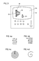
Figur 3- eine NC-Steuerung mit Bildschirm;
- Figur 4A
- eine mäanderförmige Abtastbahn;
- Figur 4B
- zwei überlagerte mäanderförmige Abtastbahnen;
- Figur 4C
- konzentrische kreisförmige Abtastbahnen und
- Figur 4D
- eine spiralförmige Abtastbahn.
- Figure 1
- a universal milling machine;
- Figure 2
- a lathe;
- Figure 3
- an NC control with screen;
- Figure 4A
- a meandering scan path;
- Figure 4B
- two superimposed meandering scanning tracks;
- Figure 4C
- concentric circular scan paths and
- Figure 4D
- a spiral scan path.
In Figur 1 ist eine Universal-Fräsmaschine 1 dargestellt, die von einer numerischen Steuerung 2 gesteuert wird.1 shows a
Auf einem Tisch 3 der Universal-Fräsmaschine 1 ist mit Spannmitteln 4 ein Werkstück 5 befestigt. Im Spindelstock 6 der Universal-Fräsmaschine 1 befindet sich ein Mehrkoordinaten-Tastkopf 7, dessen Taststift 8 das Werkstück 5 abtastet. Durch die Abtastung des Werkstückes 5 mittels des Mehrkoordinaten-Tastkopfes 7 wird die Kontur des Werkstückes 5 ermittelt.A
Die Abtastbahn, die sich aus der Relativbewegung des Tisches 3 zum Spindelstock 6 ergibt, kann gemäß Figur 4 mäanderförmig, überlagert mäanderförmig, kreisförmig, spiralförmig oder auch nach anderen Gesetzmäßigkeiten verlaufen.The scanning path, which results from the relative movement of the table 3 to the
Die jeweilige Abtastbahn entspricht auch der Relativbewegung zwischen Werkstück 5 und Mehrkoordinaten-Tastkopf 7. Die Tastsignale, die bei der Abtastung des Werkstückes 5 erzeugt werden, dienen zur Bildung der Geometriedaten des Werkstückes 5 und werden in einem Speicher 9 der numerischen Steuerung 2 abgelegt. Dieser Vorgang entspricht dem bereits eingangs beschriebenen "Digitalisieren", da die Geometriedaten des Werkstückes 5 in digitaler Form vorliegen und nun von der numerischen Steuerung 2 weiterverarbeitet werden können.The respective scanning path also corresponds to the relative movement between
Erfindungsgemäß tastet der Mehrkoordinaten-Tastkopf 7 aber nicht nur das Werkstück 5, sondern auch die Umgebung des Werkstückes 5 ab, insbesondere die Spannmittel 4 und den Tisch 3 im Bereich der Aufspannung. Die aus diesen Tastsignalen gewonnenen Daten werden ebenfalls im Speicher 9 der numerischen Steuerung 2 abgelegt.According to the invention, the
Durch den gesamten Digitalisierungsvorgang liegen nun die geometrischen Daten des Werkstückes 5 und seiner unmittelbaren Umgebung (Spannmittel 4 und Tisch 3) in digitaler Form im Speicher 9 vor. Da im Speicher 9 der numerischen Steuerung 2 auch die Daten der Werkzeuge bzw. der Werkzeugbahnen für die Bearbeitung des Werkstückes 5 in digitaler Form vorliegen, lassen sich auf einfache Weise Kollisionsbetrachtungen durchführen.Through the entire digitization process, the geometric data of the
Wenn der spätere Bearbeitungsvorgang gemäß Figur 3 vorab auf dem Bildschirm 310 der numerischen Steuerung 32 graphisch simuliert werden soll, dann lassen sich anhand der abgespeicherten - durch den Digitalisierungsvorgang ermittelten - Daten sowohl das Werkstück 35, die Spannmittel 34, der Tisch 33 und das Werkzeug 311 und seine programmierte Bewegungsbahn darstellen, und die Bedienungsperson kann visuell die Kollisionsprüfung durchführen. In Figur 3 ist dies schematisch dargestellt, wobei die Darstellung des Ausführungsbeispiels gemäß Figur 2 gewählt ist. In Figur 2 ist eine Drehmaschine 21 gezeigt, bei der die Erfindung selbstverständlich auch anwendbar ist. Sinngemäß gleichartige Elemente sind mit gleichen Bezugszeichen versehen, denen aber zur Unterscheidung jeweils die Figurenziffer vorangestellt ist.If the subsequent machining process according to FIG. 3 is to be graphically simulated beforehand on the
Die Angabe, daß nicht nur das Werkstück, sondern auch seine Umgebung zur Digitalisierung abgetastet wird, schließt die Abtastung von Werkzeugen und deren Halterungen ein.The statement that not only the workpiece but also its surroundings are scanned for digitization includes the scanning of tools and their holders.
Claims (13)
Priority Applications (3)
| Application Number | Priority Date | Filing Date | Title |
|---|---|---|---|
| EP19900106287 EP0450113B1 (en) | 1990-04-02 | 1990-04-02 | Digitizing method with collision testing |
| DE59009295T DE59009295D1 (en) | 1990-04-02 | 1990-04-02 | Digitizing procedure with collision check. |
| DE19904017496 DE4017496A1 (en) | 1990-04-02 | 1990-05-31 | DIGITALIZATION PROCESS WITH COLLISION CHECK |
Applications Claiming Priority (1)
| Application Number | Priority Date | Filing Date | Title |
|---|---|---|---|
| EP19900106287 EP0450113B1 (en) | 1990-04-02 | 1990-04-02 | Digitizing method with collision testing |
Publications (2)
| Publication Number | Publication Date |
|---|---|
| EP0450113A1 true EP0450113A1 (en) | 1991-10-09 |
| EP0450113B1 EP0450113B1 (en) | 1995-06-21 |
Family
ID=8203848
Family Applications (1)
| Application Number | Title | Priority Date | Filing Date |
|---|---|---|---|
| EP19900106287 Expired - Lifetime EP0450113B1 (en) | 1990-04-02 | 1990-04-02 | Digitizing method with collision testing |
Country Status (2)
| Country | Link |
|---|---|
| EP (1) | EP0450113B1 (en) |
| DE (2) | DE59009295D1 (en) |
Cited By (5)
| Publication number | Priority date | Publication date | Assignee | Title |
|---|---|---|---|---|
| DE4331034A1 (en) * | 1993-09-13 | 1995-03-16 | Grundig Ag | Method for determining the two-dimensional contour of a work area for lathes |
| EP0697639A1 (en) * | 1994-08-15 | 1996-02-21 | Toshiba Kikai Kabushiki Kaisha | Method for checking interference, method for checking processing program, and method for checking processing propriety |
| EP0703517A1 (en) * | 1994-09-23 | 1996-03-27 | Carl Zeiss | Procedure for measuring of workpieces with a handguided coordinate measuring device |
| WO2008025577A1 (en) * | 2006-05-30 | 2008-03-06 | Siemens Aktiengesellschaft | Method and device for monitoring a machine element to prevent its collision with an object in a machine tool, a production machine and/or a machine that is configured as a robot |
| CN106041644A (en) * | 2016-08-07 | 2016-10-26 | 张民胜 | Numerical control machine tool with collision detector |
Citations (3)
| Publication number | Priority date | Publication date | Assignee | Title |
|---|---|---|---|---|
| GB2140937A (en) * | 1983-05-10 | 1984-12-05 | Philips Nv | Simulation of machine tools |
| DE3816933A1 (en) * | 1987-05-18 | 1988-12-08 | Israel Aircraft Ind Ltd | DEVICE FOR AUTOMATIC AFTER AND CONTOUR MEASUREMENT |
| EP0328750A2 (en) * | 1988-02-16 | 1989-08-23 | Dr. Johannes Heidenhain GmbH | Copying device |
-
1990
- 1990-04-02 DE DE59009295T patent/DE59009295D1/en not_active Expired - Fee Related
- 1990-04-02 EP EP19900106287 patent/EP0450113B1/en not_active Expired - Lifetime
- 1990-05-31 DE DE19904017496 patent/DE4017496A1/en not_active Withdrawn
Patent Citations (3)
| Publication number | Priority date | Publication date | Assignee | Title |
|---|---|---|---|---|
| GB2140937A (en) * | 1983-05-10 | 1984-12-05 | Philips Nv | Simulation of machine tools |
| DE3816933A1 (en) * | 1987-05-18 | 1988-12-08 | Israel Aircraft Ind Ltd | DEVICE FOR AUTOMATIC AFTER AND CONTOUR MEASUREMENT |
| EP0328750A2 (en) * | 1988-02-16 | 1989-08-23 | Dr. Johannes Heidenhain GmbH | Copying device |
Non-Patent Citations (1)
| Title |
|---|
| VDI ZEITSCHRIFT, vol. 125, no. 17, September 1983, DUSSELDORF, DE; Seiten 647 - 652; Schöling und Reles: "Offline-Kollisionskontrolle bei Industrierobotern" * |
Cited By (9)
| Publication number | Priority date | Publication date | Assignee | Title |
|---|---|---|---|---|
| DE4331034A1 (en) * | 1993-09-13 | 1995-03-16 | Grundig Ag | Method for determining the two-dimensional contour of a work area for lathes |
| WO1995008142A1 (en) * | 1993-09-13 | 1995-03-23 | Grundig Aktiengesellschaft | Process for the two-dimensional determination of a work-area contour for lathes |
| US5654618A (en) * | 1993-09-13 | 1997-08-05 | Dr. Johannes Heidenhain Gmbh | Process for the two-dimensional determination of a work-area contour for lathes |
| EP0697639A1 (en) * | 1994-08-15 | 1996-02-21 | Toshiba Kikai Kabushiki Kaisha | Method for checking interference, method for checking processing program, and method for checking processing propriety |
| US5751584A (en) * | 1994-08-15 | 1998-05-12 | Toshiba Kikai Kabushiki Kaisha | Method for checking interference, method for checking processing program, and method for checking processing propriety |
| EP0703517A1 (en) * | 1994-09-23 | 1996-03-27 | Carl Zeiss | Procedure for measuring of workpieces with a handguided coordinate measuring device |
| US5724745A (en) * | 1994-09-23 | 1998-03-10 | Carl-Zeiss-Stiftung | Method and manually guide coordinate measuring apparatus for measuring a workpiece |
| WO2008025577A1 (en) * | 2006-05-30 | 2008-03-06 | Siemens Aktiengesellschaft | Method and device for monitoring a machine element to prevent its collision with an object in a machine tool, a production machine and/or a machine that is configured as a robot |
| CN106041644A (en) * | 2016-08-07 | 2016-10-26 | 张民胜 | Numerical control machine tool with collision detector |
Also Published As
| Publication number | Publication date |
|---|---|
| DE4017496A1 (en) | 1991-10-10 |
| DE59009295D1 (en) | 1995-07-27 |
| EP0450113B1 (en) | 1995-06-21 |
Similar Documents
| Publication | Publication Date | Title |
|---|---|---|
| EP0328750B1 (en) | Copying device | |
| DE3805500C2 (en) | ||
| DE3590550T1 (en) | Coordinate measuring instrument | |
| DE2934347A1 (en) | METHOD AND TEST DEVICE FOR TESTING THE TOOTHED FRAME PROFILE OF GEARS WITH LARGE DIAMETERS | |
| DE102016220127A1 (en) | Method for operating a coordinate measuring machine | |
| EP3403051B1 (en) | Method and device for specifying specification data for a measurement of a workpiece to be measured by means of a coordinate measuring device and/or for an analysis of measurement results of a measurement of a measured workpiece by means of a coordinate measuring device | |
| EP1078305B1 (en) | Coordinate measurement device and method for controlling same | |
| DE4223483C2 (en) | Procedure for determining the shape and position deviations of production parts | |
| EP0450113B1 (en) | Digitizing method with collision testing | |
| DE2023490A1 (en) | Device for the relative movement of two bodies | |
| DE4412961A1 (en) | Method for scanning the surface of an object | |
| DE69921013T2 (en) | Workpiece shape measuring method and apparatus, and Koördinatenmessmaschine | |
| EP1316777A1 (en) | Method and device for the three dimensional measuring of workpieces on a machine tool | |
| DE102017007078A1 (en) | Measuring system and method for determining 3D coordinates of measuring points of an object, in particular a forming tool for the production of vehicles | |
| DE102007044000A1 (en) | Method for determining three dimensional-shape of work-piece, involves measuring space coordinates from surface points of work-piece, where space coordinate is correlated with predetermined surfaces or curves | |
| DE102020206463A1 (en) | Robot programming system | |
| DE3110271C2 (en) | Drawing facility | |
| WO1982000906A1 (en) | Method and device for shaping a surface of a workpiece | |
| EP0719428B1 (en) | Process for the two-dimensional determination of a work-area contour for lathes | |
| DE3634688A1 (en) | METHOD AND DEVICE FOR MEASURING GEARS BY MEANS OF A COORDINATE MEASURING DEVICE | |
| EP0613573B1 (en) | Process for testing the working accuracy of an nc machine | |
| DE3817454C2 (en) | ||
| EP0326625A1 (en) | Apparatus for determining irregularities in a tool machine for machining work pieces | |
| DE2707278A1 (en) | METHOD OF CHECKING THE DIMENSIONS OF A WORKPIECE MACHINED IN A MACHINE TOOL | |
| DE4220257C2 (en) | Method and device for labeling and / or processing workpieces with an undefined shape surface |
Legal Events
| Date | Code | Title | Description |
|---|---|---|---|
| PUAI | Public reference made under article 153(3) epc to a published international application that has entered the european phase |
Free format text: ORIGINAL CODE: 0009012 |
|
| 17P | Request for examination filed |
Effective date: 19900414 |
|
| AK | Designated contracting states |
Kind code of ref document: A1 Designated state(s): AT CH DE FR GB IT LI NL |
|
| 17Q | First examination report despatched |
Effective date: 19931105 |
|
| ITF | It: translation for a ep patent filed |
Owner name: DE DOMINICIS & MAYER S.R.L. |
|
| RBV | Designated contracting states (corrected) |
Designated state(s): DE FR GB IT |
|
| GRAA | (expected) grant |
Free format text: ORIGINAL CODE: 0009210 |
|
| AK | Designated contracting states |
Kind code of ref document: B1 Designated state(s): DE FR GB IT |
|
| ET | Fr: translation filed | ||
| GBT | Gb: translation of ep patent filed (gb section 77(6)(a)/1977) |
Effective date: 19950627 |
|
| REF | Corresponds to: |
Ref document number: 59009295 Country of ref document: DE Date of ref document: 19950727 |
|
| PLBE | No opposition filed within time limit |
Free format text: ORIGINAL CODE: 0009261 |
|
| STAA | Information on the status of an ep patent application or granted ep patent |
Free format text: STATUS: NO OPPOSITION FILED WITHIN TIME LIMIT |
|
| 26N | No opposition filed | ||
| REG | Reference to a national code |
Ref country code: GB Ref legal event code: IF02 |
|
| PGFP | Annual fee paid to national office [announced via postgrant information from national office to epo] |
Ref country code: GB Payment date: 20040331 Year of fee payment: 15 |
|
| PGFP | Annual fee paid to national office [announced via postgrant information from national office to epo] |
Ref country code: FR Payment date: 20040415 Year of fee payment: 15 |
|
| PG25 | Lapsed in a contracting state [announced via postgrant information from national office to epo] |
Ref country code: IT Free format text: LAPSE BECAUSE OF NON-PAYMENT OF DUE FEES;WARNING: LAPSES OF ITALIAN PATENTS WITH EFFECTIVE DATE BEFORE 2007 MAY HAVE OCCURRED AT ANY TIME BEFORE 2007. THE CORRECT EFFECTIVE DATE MAY BE DIFFERENT FROM THE ONE RECORDED. Effective date: 20050402 Ref country code: GB Free format text: LAPSE BECAUSE OF NON-PAYMENT OF DUE FEES Effective date: 20050402 |
|
| GBPC | Gb: european patent ceased through non-payment of renewal fee |
Effective date: 20050402 |
|
| PG25 | Lapsed in a contracting state [announced via postgrant information from national office to epo] |
Ref country code: FR Free format text: LAPSE BECAUSE OF NON-PAYMENT OF DUE FEES Effective date: 20051230 |
|
| REG | Reference to a national code |
Ref country code: FR Ref legal event code: ST Effective date: 20051230 |
|
| PGFP | Annual fee paid to national office [announced via postgrant information from national office to epo] |
Ref country code: DE Payment date: 20080418 Year of fee payment: 19 |
|
| PG25 | Lapsed in a contracting state [announced via postgrant information from national office to epo] |
Ref country code: DE Free format text: LAPSE BECAUSE OF NON-PAYMENT OF DUE FEES Effective date: 20091103 |