EP0450281A1 - Multipolar electric connector - Google Patents
Multipolar electric connector Download PDFInfo
- Publication number
- EP0450281A1 EP0450281A1 EP91101743A EP91101743A EP0450281A1 EP 0450281 A1 EP0450281 A1 EP 0450281A1 EP 91101743 A EP91101743 A EP 91101743A EP 91101743 A EP91101743 A EP 91101743A EP 0450281 A1 EP0450281 A1 EP 0450281A1
- Authority
- EP
- European Patent Office
- Prior art keywords
- section
- plug
- oval
- socket
- flat
- Prior art date
- Legal status (The legal status is an assumption and is not a legal conclusion. Google has not performed a legal analysis and makes no representation as to the accuracy of the status listed.)
- Granted
Links
Images

Classifications
-
- H—ELECTRICITY
- H01—ELECTRIC ELEMENTS
- H01R—ELECTRICALLY-CONDUCTIVE CONNECTIONS; STRUCTURAL ASSOCIATIONS OF A PLURALITY OF MUTUALLY-INSULATED ELECTRICAL CONNECTING ELEMENTS; COUPLING DEVICES; CURRENT COLLECTORS
- H01R13/00—Details of coupling devices of the kinds covered by groups H01R12/70 or H01R24/00 - H01R33/00
- H01R13/62—Means for facilitating engagement or disengagement of coupling parts or for holding them in engagement
- H01R13/627—Snap or like fastening
- H01R13/6271—Latching means integral with the housing
-
- H—ELECTRICITY
- H01—ELECTRIC ELEMENTS
- H01R—ELECTRICALLY-CONDUCTIVE CONNECTIONS; STRUCTURAL ASSOCIATIONS OF A PLURALITY OF MUTUALLY-INSULATED ELECTRICAL CONNECTING ELEMENTS; COUPLING DEVICES; CURRENT COLLECTORS
- H01R13/00—Details of coupling devices of the kinds covered by groups H01R12/70 or H01R24/00 - H01R33/00
- H01R13/46—Bases; Cases
- H01R13/52—Dustproof, splashproof, drip-proof, waterproof, or flameproof cases
Definitions
- the invention relates to a multi-pole electrical connector according to the preamble of claim 1.
- Electrical connectors of the above Kinds that are mainly used in motor vehicles, especially commercial vehicles, must be able to withstand increased stresses such as heat, cold, vibrations, dirt, stone chips and moisture (splash water). They must therefore be particularly robust and reliable, especially if the cables to be connected fulfill functions that are important for the safety of the vehicle, e.g. Anti-lock braking systems or electrical braking systems.
- Another aspect is the easiest possible assembly and disassembly, even under unfavorable conditions such as poor visibility due to hidden installation position or insufficient lighting.
- the manufacturing and assembly costs of the plug device must also be as low as possible.
- the holding force of the plug device in the plugged-together state must be sufficiently high to prevent it from coming loose on its own.
- locking devices are known (EP-PS 187 887), which hold the plug part and the socket together with a defined force.
- the known plug-in device is not robust enough for use in the motor vehicle.
- the invention is based on the object of specifying a plug-in device of the type mentioned at the outset which fulfills the difficult operating conditions mentioned above and, in addition, is particularly small in the case of a given current and voltage load capacity.
- the diameter should be as small as possible in order to be able to use the plug device even in confined spaces.
- the plug-in device according to the invention fulfills the requirements mentioned by the flat or oval design of its central part.
- known designs have either a continuously round or continuously flat cross section. Due to the peculiar design of the plug-in device according to the invention with round end sections and an oval or flat middle section, it was possible to maintain the required electrical and mechanical values with minimal or predetermined dimensions.
- the plug device according to the invention is shown in side view, partially in section. It consists of a plug (4) and a socket (5) with which two cables (6) and (7) can be connected.
- the parts (4) and (5) are made of plastic, namely a variety that must meet the required conditions with regard to heat and cold stress.
- the outer diameter of the plug device can typically be approximately 10-20 mm.
- Two contact pins (1, 2) face two contact sleeves (14, 15).
- the plug device has a circular cross section in area (A), a flat or oval cross section in area (B) and a circular cross section again in area (C).
- the contact pins and sleeves are arranged side by side on the longitudinal axis (3) of the oval section (B) (see view D-D and E-E).
- a locking device with a defined separating force serves to keep the plug closed.
- This device consists of a snap connection with two cams (8, 9) which are arranged on the flat side of the oval section (B) of the plug (4).
- the cams (8, 9) can be snapped into corresponding cutouts (10, 11) in the bushing (5). These are located on the broad side of the oval housing part (13) of the socket (5) (see Fig. 2).
- Views F-F and G-G serve to illustrate the transition from the round part (A, C) to the flat part (B).
- a sealing device which consists of an O-ring (12) which, due to its elasticity, adapts to the oval or flat cross section of the plug part. This is inserted in a groove in the connector (4).
- the O-ring lies against the inner wall of the oval housing part (13) of the socket (5) and thus seals the plug device against the ingress of moisture.
- a particular advantage of the plug-in device according to the invention over a round design is that the position of the plug and socket can also be felt blindly due to the flat central part (B). As a result, the plug device can also be plugged together without a view.
- twisting or interchanging the contacts (1, 2) does not matter when plugging them together.
- it can be achieved by further known measures, for example by a cam and a suitable groove, coding the plug device, so that polarity reversal is then excluded.
Abstract
Description
Die Erfindung bezieht sich auf eine mehrpolige elektrische Steckvorrichtung gemäß dem Oberbegriff des Patentanspruchs 1.The invention relates to a multi-pole electrical connector according to the preamble of claim 1.
Elektrische Steckvorrichtungen der o.g. Art, die vorwiegend in Kraftfahrzeugen, insbesondere Nutzfahrzeugen eingesetzt sind, müssen im Betrieb erhöhte Beanspruchungen wie Hitze, Kälte, Vibrationen, Schmutz, Steinschlag und Feuchtigkeit (Spritzwasser) aushalten können. Sie müssen daher besonders robust und zuverlässig gebaut sein, besonders wenn die zu verbindenden Kabel Funktionen erfüllen, die für die Sicherheit des Fahrzeuges wichtig sind, wie z.B. Antiblockiersysteme oder elektrische Bremssysteme.Electrical connectors of the above Kinds that are mainly used in motor vehicles, especially commercial vehicles, must be able to withstand increased stresses such as heat, cold, vibrations, dirt, stone chips and moisture (splash water). They must therefore be particularly robust and reliable, especially if the cables to be connected fulfill functions that are important for the safety of the vehicle, e.g. Anti-lock braking systems or electrical braking systems.
Ein weiterer Gesichtspunkt ist eine möglichst leichte Montier- und Demontierbarkeit, und zwar auch unter ungünstigen Bedingungen, wie schlechte Sicht durch versteckte Einbaulage oder unzureichende Beleuchtung.Another aspect is the easiest possible assembly and disassembly, even under unfavorable conditions such as poor visibility due to hidden installation position or insufficient lighting.
Als Kfz-Serienbauteil mit großer Stückzahl müssen ferner die Herstellungs- und Montagekosten der Steckvorrichtung möglichst niedrig sein.As a large-volume automotive component, the manufacturing and assembly costs of the plug device must also be as low as possible.
Schließlich muß die Haltekraft der Steckvorrichtung im zusammengesteckten Zustand ausreichend hoch sein, um ein selbständiges Lösen zu verhindern. Hierzu sind Rastvorrichtungen bekannt (EP-PS 187 887), welche den Steckerteil und die Buchse mit einer definierten Kraft zusammenhalten. Die bekannte Steckvorrichtung ist jedoch für den Einsatz im Kraftfahrzeug nicht robust genug aufgebaut.Finally, the holding force of the plug device in the plugged-together state must be sufficiently high to prevent it from coming loose on its own. For this purpose, locking devices are known (EP-PS 187 887), which hold the plug part and the socket together with a defined force. However, the known plug-in device is not robust enough for use in the motor vehicle.
Der Erfindung liegt die Aufgabe zugrunde, eine Steckvorrichtung der eingangs genannten Art anzugeben, welche die oben angeführten erschwerten Betriebsbedingungen erfüllt und zudem bei einer vorgegebenen Strom- und Spannungsbelastbarkeit besonders klein baut. Insbesondere soll der Durchmesser möglichst gering sein, um die Steckvorrichtung auch bei beengten Verhältnissen einsetzen zu können.The invention is based on the object of specifying a plug-in device of the type mentioned at the outset which fulfills the difficult operating conditions mentioned above and, in addition, is particularly small in the case of a given current and voltage load capacity. In particular, the diameter should be as small as possible in order to be able to use the plug device even in confined spaces.
Diese Aufgabe wird durch die im Patentanspruch 1 enthaltenen Merkmale erfüllt. Die Unteransprüche enthalten zweckmäßige Weiterbildungen der Erfindung.This object is achieved by the features contained in claim 1. The dependent claims contain expedient developments of the invention.
Die erfindungsgemäße Steckvorrichtung erfüllt die genannten Anforderungen durch die flache bzw. ovale Ausbildung ihres Mittelteils. Bekannte Ausführungen haben im Gegensatz zur Erfindung entweder einen durchgehend runden oder durchgehend flachen Querschnitt. Durch die eigentümliche Ausbildung der erfindungsgemäßen Steckvorrichtung mit runden Endabschnitten und einem ovalen oder flachen Mittelabschnitt war es möglich, die geforderten elektrischen und mechanischen Werte bei minimalen bzw. vorgegebenen Abmessungen einzuhalten.The plug-in device according to the invention fulfills the requirements mentioned by the flat or oval design of its central part. In contrast to the invention, known designs have either a continuously round or continuously flat cross section. Due to the peculiar design of the plug-in device according to the invention with round end sections and an oval or flat middle section, it was possible to maintain the required electrical and mechanical values with minimal or predetermined dimensions.
Die Erfindung wird im folgenden anhand einer Zeichnung näher erläutert.The invention is explained below with reference to a drawing.
Diese zeigt in
- Fig.1
- eine Seitenansicht der erfindungsgemäßen Steckvorrichtung im getrennten Zustand,
- Fig.2
- die Ansicht von Fig.1 um 90° gedreht,
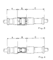
- Fig.3
- eine Seitenansicht der Steckvorrichtung im zusammengesteckten Zustand,
- Fig.4
- die Ansicht von Fig.3 um 90° gedreht.
- Fig. 1
- a side view of the plug device according to the invention in the separated state,
- Fig. 2
- 1 rotated by 90 °,
- Fig. 3
- 2 shows a side view of the plug device in the assembled state,
- Fig. 4
- the view of Figure 3 rotated by 90 °.
In Fig.1 ist die Steckvorrichtung gemäß der Erfindung in der Seitenansicht, teilweise geschnitten, dargestellt. Sie besteht aus einem Stecker (4) und einer Buchse (5), mit welcher zwei Kabel (6) und (7) verbindbar sind. Die Teile (4) und (5) sind aus Kunststoff, und zwar einer Sorte, die den geforderten Bedingungen hinsichtlich Hitze- und Kältebeanspruchung genügen muß. Der Außendurchmesser der Steckvorrichtung kann typischerweise etwa 10 - 20 mm betragen.In Figure 1, the plug device according to the invention is shown in side view, partially in section. It consists of a plug (4) and a socket (5) with which two cables (6) and (7) can be connected. The parts (4) and (5) are made of plastic, namely a variety that must meet the required conditions with regard to heat and cold stress. The outer diameter of the plug device can typically be approximately 10-20 mm.
Zwei Kontaktstiften (1, 2) stehen zwei Kontakthülsen (14, 15) gegenüber.Two contact pins (1, 2) face two contact sleeves (14, 15).
Die Steckvorrichtung hat im Bereich (A) einen kreisförmigen, im Bereich (B) einen flachen bzw. ovalen und im Bereich (C) wieder einen kreisförmigen Querschnitt. Die Kontaktstifte und -hülsen sind auf der Längsachse (3) des ovalen Abschnitts (B) nebeneinander angeordnet (vergl. Ansicht D-D und E-E).The plug device has a circular cross section in area (A), a flat or oval cross section in area (B) and a circular cross section again in area (C). The contact pins and sleeves are arranged side by side on the longitudinal axis (3) of the oval section (B) (see view D-D and E-E).
Im zusammengesteckten Zustand der Steckvorrichtung (siehe Figuren 3 und 4) dient eine Verriegelungsvorrichtung mit definierter Trennkraft dazu, den Stecker geschlossen zu halten. Diese Vorrichtung besteht aus einer Schnappverbindung mit zwei Nocken (8, 9), welche auf der flachen Seite des ovalen Abschnitts (B) des Steckers (4) angeordnet sind. Die Nocken (8, 9) sind im eingesteckten Zustand in entsprechende Ausschnitte (10, 11) der Buchse (5) einrastbar. Diese befinden sich auf der Breitseite des ovalen Gehäuseteiles (13) der Buchse (5) (siehe Fig.2).In the plugged-together state of the plug device (see FIGS. 3 and 4), a locking device with a defined separating force serves to keep the plug closed. This device consists of a snap connection with two cams (8, 9) which are arranged on the flat side of the oval section (B) of the plug (4). When inserted, the cams (8, 9) can be snapped into corresponding cutouts (10, 11) in the bushing (5). These are located on the broad side of the oval housing part (13) of the socket (5) (see Fig. 2).
Durch die Anordnung der Ausschnitte (10, 11) auf der Breitseite des Gehäuseteils (13) federt dieses beim Einstecken besonders leicht zurück. Dies wäre bei einer runden Ausbildung nicht der Fall. Hierdurch läßt sich auch die Trennkraft beim Lösen der Steckvorrichtung genauer vorgeben.Due to the arrangement of the cutouts (10, 11) on the broad side of the housing part (13), this springs back particularly easily when inserted. This would not be the case with a round education. This allows also specify the separation force when loosening the connector.
Andererseits wäre es natürlich auch möglich, die Außenkontur des Teils (13) rund auszubilden.On the other hand, it would of course also be possible to make the outer contour of the part (13) round.
Die Ansichten F-F sowie G-G dienen zur Verdeutlichung des Überganges vom runden Teil (A, C) zum flachen Teil (B).Views F-F and G-G serve to illustrate the transition from the round part (A, C) to the flat part (B).
Schließlich ist noch eine Dichteinrichtung vorgesehen, die aus einem O-Ring (12) besteht, der sich aufgrund seiner Elastizität dem ovalen oder flachen Querschnitt des Steckerteils anpaßt. Dieser ist in einer Nut des Steckers (4) eingelegt. Im eingesteckten Zustand der Steckvorrichtung liegt der O-Ring an der Innenwand des ovalen Gehäuseteiles (13) der Buchse (5) an und dichtet so die Steckvorrichtung gegen das Eindringen von Feuchtigkeit ab.Finally, a sealing device is provided, which consists of an O-ring (12) which, due to its elasticity, adapts to the oval or flat cross section of the plug part. This is inserted in a groove in the connector (4). When the plug device is plugged in, the O-ring lies against the inner wall of the oval housing part (13) of the socket (5) and thus seals the plug device against the ingress of moisture.
Ein besonderer Vorteil der erfindungsgemäßen Steckvorrichtung gegenüber einer durchgehend runden Ausführung liegt darin, daß sich die Stellung von Stecker und Buchse infolge des flachen Mittelteils (B) auch blind ertasten läßt. Hierdurch läßt sich die Steckvorrichtung auch ohne Sicht zusammenstecken.A particular advantage of the plug-in device according to the invention over a round design is that the position of the plug and socket can also be felt blindly due to the flat central part (B). As a result, the plug device can also be plugged together without a view.
Bei dem gezeichneten Ausführungsbeispiel spielt eine Verdrehung bzw. Vertauschung der Kontakte (1, 2) beim Zusammenstecken keine Rolle. Es läßt sich jedoch durch weitere, bekannte Maßnahmen, beispielsweise durch einen Nocken und eine passende Nut, eine Codierung der Steckvorrichtung erzielen, so daß dann eine Verpolung ausgeschlossen ist.In the exemplary embodiment shown, twisting or interchanging the contacts (1, 2) does not matter when plugging them together. However, it can be achieved by further known measures, for example by a cam and a suitable groove, coding the plug device, so that polarity reversal is then excluded.
Claims (3)
Applications Claiming Priority (2)
| Application Number | Priority Date | Filing Date | Title |
|---|---|---|---|
| DE4010836 | 1990-04-04 | ||
| DE4010836A DE4010836A1 (en) | 1990-04-04 | 1990-04-04 | MULTIPOLE ELECTRICAL CONNECTOR |
Publications (2)
| Publication Number | Publication Date |
|---|---|
| EP0450281A1 true EP0450281A1 (en) | 1991-10-09 |
| EP0450281B1 EP0450281B1 (en) | 1995-04-05 |
Family
ID=6403725
Family Applications (1)
| Application Number | Title | Priority Date | Filing Date |
|---|---|---|---|
| EP91101743A Expired - Lifetime EP0450281B1 (en) | 1990-04-04 | 1991-02-08 | Multipolar electric connector |
Country Status (5)
| Country | Link |
|---|---|
| US (1) | US5368499A (en) |
| EP (1) | EP0450281B1 (en) |
| JP (1) | JP3127247B2 (en) |
| CZ (1) | CZ280357B6 (en) |
| DE (2) | DE4010836A1 (en) |
Cited By (3)
| Publication number | Priority date | Publication date | Assignee | Title |
|---|---|---|---|---|
| CH683470A5 (en) * | 1992-05-07 | 1994-03-15 | Kupferdraht Isolierwerk Ag | A releasable coupling device with separation assurance. |
| WO1999062145A1 (en) * | 1998-05-27 | 1999-12-02 | Tyco Electronics Corporation | Electrical connector with split shells and retention clip and method of assembling the connector |
| EP2777096B1 (en) | 2011-11-09 | 2018-04-04 | LQ Mechatronik-Systeme GmbH | Multi-pole plug connection unit for three-phase alternating current systems |
Families Citing this family (25)
| Publication number | Priority date | Publication date | Assignee | Title |
|---|---|---|---|---|
| US6755676B2 (en) | 1995-07-07 | 2004-06-29 | Henry Milan | Modular outlet strip |
| US5605468A (en) * | 1995-11-22 | 1997-02-25 | Tescorp Seismic Products, Inc. | Electrical connector assembly having replaceable sleeve seal |
| US6093045A (en) * | 1996-03-13 | 2000-07-25 | Osram Sylvania Inc. | Electrical connector module and kit having tamper proof latch mechanism |
| US6022237A (en) * | 1997-02-26 | 2000-02-08 | John O. Esh | Water-resistant electrical connector |
| JP2000040547A (en) * | 1998-07-22 | 2000-02-08 | Sumitomo Wiring Syst Ltd | Connector for electrical connection |
| DE19859417A1 (en) * | 1998-12-22 | 2000-07-20 | Taller Gmbh | Sensor coupling |
| US7160149B1 (en) * | 2005-06-24 | 2007-01-09 | John Mezzalingua Associates, Inc. | Coaxial connector and method of connecting a two-wire cable to a coaxial connector |
| US20070077824A1 (en) * | 2005-08-04 | 2007-04-05 | Dustin Brown | Connector assembly |
| KR100763239B1 (en) * | 2006-06-27 | 2007-10-04 | 삼성전자주식회사 | Image processing apparatus and method for enhancing visibility of image on display |
| US7833037B2 (en) * | 2007-03-16 | 2010-11-16 | Allied Precision Industries, Inc. | Cordset assembly |
| US7780478B2 (en) * | 2007-06-28 | 2010-08-24 | Apple Inc. | Apparatus and methods for connecting two electrical devices together |
| JP2011045526A (en) * | 2009-08-27 | 2011-03-10 | Nakanishi:Kk | Connection structure of motor unit to power cord of dental handpiece |
| US7997931B2 (en) * | 2009-12-11 | 2011-08-16 | Aerovironment, Inc. | Waterproof electrical connector and system |
| JP4633856B1 (en) * | 2010-04-02 | 2011-02-23 | 紀文 伊島 | Receptacle connector |
| US20120004655A1 (en) * | 2010-06-30 | 2012-01-05 | Harrison Jay Kim | Bipolar Connector System |
| EP3761458A1 (en) | 2012-07-16 | 2021-01-06 | CommScope, Inc. of North Carolina | Balanced pin and socket connectors |
| US8888535B2 (en) * | 2012-09-10 | 2014-11-18 | Shur-Co, Llc | Corrosion resistant electrical assembly with connectors and multi-port junction block |
| JP6136052B2 (en) * | 2013-08-20 | 2017-05-31 | ヒロセ電機株式会社 | Connector with deformable housing |
| GB2547958B (en) | 2016-03-04 | 2019-12-18 | Commscope Technologies Llc | Two-wire plug and receptacle |
| MX2019011906A (en) | 2017-04-24 | 2019-11-25 | Commscope Technologies Llc | Connectors for a single twisted pair of conductors. |
| US11271350B2 (en) | 2017-06-08 | 2022-03-08 | Commscope Technologies Llc | Connectors for a single twisted pair of conductors |
| US11296463B2 (en) | 2018-01-26 | 2022-04-05 | Commscope Technologies Llc | Connectors for a single twisted pair of conductors |
| DE102018101964B3 (en) * | 2018-01-30 | 2019-06-13 | Te Connectivity Germany Gmbh | Connector and connector receptacle |
| AU2019223204A1 (en) | 2018-02-26 | 2020-09-17 | Commscope Technologies Llc | Connectors and contacts for a single twisted pair of conductors |
| EP3939129A4 (en) | 2019-03-15 | 2022-12-14 | CommScope Technologies LLC | Connectors and contacts for a single twisted pair of conductors |
Citations (4)
| Publication number | Priority date | Publication date | Assignee | Title |
|---|---|---|---|---|
| US3471824A (en) * | 1964-04-23 | 1969-10-07 | Bosch Gmbh Robert | Plug and socket connection |
| FR2354647A1 (en) * | 1976-06-09 | 1978-01-06 | Cemrep | Plug and socket cable connector - is locked together by two hooked tie strips engaging over two screw tightened loops |
| US4211461A (en) * | 1978-11-27 | 1980-07-08 | Industrial Electronic Hardware Corp. | Axially mating cable connector |
| EP0187887A1 (en) * | 1985-01-18 | 1986-07-23 | Hosiden Electronics Co., Ltd. | Connector with lock mechanism |
Family Cites Families (11)
| Publication number | Priority date | Publication date | Assignee | Title |
|---|---|---|---|---|
| US1981460A (en) * | 1929-08-07 | 1934-11-20 | James B Miller | Cable connecter |
| US3199060A (en) * | 1962-09-11 | 1965-08-03 | Nottingham & Co Inc J B | Cable connector assembly |
| US3166371A (en) * | 1962-09-13 | 1965-01-19 | Elastic Stop Nut Corp | Waterproof electrical connector |
| US3601761A (en) * | 1969-08-28 | 1971-08-24 | Arthur M Harris | Waterproof locking-type electric plug and receptacle coupling |
| US3685004A (en) * | 1970-12-14 | 1972-08-15 | Schlumberger Technology Corp | Underwater pressure break connector |
| GB1362265A (en) * | 1971-03-12 | 1974-08-07 | Cannon Electric Great Britain | Electrical connectors |
| US4150866A (en) * | 1977-08-26 | 1979-04-24 | Amp Incorporated | Environmentally sealed connector |
| CA1138973A (en) * | 1978-10-23 | 1983-01-04 | Robert G. Plyler | Weatherproof electric connector |
| US4611872A (en) * | 1983-09-21 | 1986-09-16 | Tokai Electric Wire Company Limited | Water-proof connector |
| US4772231A (en) * | 1986-11-07 | 1988-09-20 | Amp Incorporated | Unitary molded sealed connector with modular keying and terminal retention |
| US4940420A (en) * | 1989-08-17 | 1990-07-10 | Ford Motor Company | Electrical connector with retained boot |
-
1990
- 1990-04-04 DE DE4010836A patent/DE4010836A1/en not_active Ceased
-
1991
- 1991-02-08 EP EP91101743A patent/EP0450281B1/en not_active Expired - Lifetime
- 1991-02-08 DE DE59105070T patent/DE59105070D1/en not_active Expired - Lifetime
- 1991-03-28 US US07/676,893 patent/US5368499A/en not_active Expired - Lifetime
- 1991-03-28 JP JP03133665A patent/JP3127247B2/en not_active Expired - Lifetime
- 1991-04-04 CZ CS91931A patent/CZ280357B6/en not_active IP Right Cessation
Patent Citations (4)
| Publication number | Priority date | Publication date | Assignee | Title |
|---|---|---|---|---|
| US3471824A (en) * | 1964-04-23 | 1969-10-07 | Bosch Gmbh Robert | Plug and socket connection |
| FR2354647A1 (en) * | 1976-06-09 | 1978-01-06 | Cemrep | Plug and socket cable connector - is locked together by two hooked tie strips engaging over two screw tightened loops |
| US4211461A (en) * | 1978-11-27 | 1980-07-08 | Industrial Electronic Hardware Corp. | Axially mating cable connector |
| EP0187887A1 (en) * | 1985-01-18 | 1986-07-23 | Hosiden Electronics Co., Ltd. | Connector with lock mechanism |
Cited By (5)
| Publication number | Priority date | Publication date | Assignee | Title |
|---|---|---|---|---|
| CH683470A5 (en) * | 1992-05-07 | 1994-03-15 | Kupferdraht Isolierwerk Ag | A releasable coupling device with separation assurance. |
| WO1999062145A1 (en) * | 1998-05-27 | 1999-12-02 | Tyco Electronics Corporation | Electrical connector with split shells and retention clip and method of assembling the connector |
| US6478631B1 (en) | 1998-05-27 | 2002-11-12 | Tyco Electronics Corporation | Electrical connector with split shells and retention clip |
| EP2777096B1 (en) | 2011-11-09 | 2018-04-04 | LQ Mechatronik-Systeme GmbH | Multi-pole plug connection unit for three-phase alternating current systems |
| EP2777096B2 (en) † | 2011-11-09 | 2021-06-16 | LQ Mechatronik-Systeme GmbH | Multi-pole plug connection unit for three-phase alternating current systems |
Also Published As
| Publication number | Publication date |
|---|---|
| JP3127247B2 (en) | 2001-01-22 |
| EP0450281B1 (en) | 1995-04-05 |
| CS9100931A2 (en) | 1991-12-17 |
| CZ280357B6 (en) | 1995-12-13 |
| JPH04230975A (en) | 1992-08-19 |
| US5368499A (en) | 1994-11-29 |
| DE4010836A1 (en) | 1991-10-10 |
| DE59105070D1 (en) | 1995-05-11 |
Similar Documents
| Publication | Publication Date | Title |
|---|---|---|
| EP0450281B1 (en) | Multipolar electric connector | |
| EP2510590B1 (en) | System plug connector having an adapter module | |
| DE19813458B4 (en) | Electrical connector | |
| EP1831984A2 (en) | Adapter for use with an electrical microdrive | |
| EP2548265A1 (en) | High current connector | |
| DE102007006859A1 (en) | contact | |
| DE102005012441B4 (en) | Electrical connector and method of making an electrical connector | |
| DE4419023A1 (en) | Fitted plug connector | |
| DE3835755C2 (en) | ||
| EP0968548A1 (en) | Socket with contact regions disposed in the form of a hyperboloid | |
| EP1154521B1 (en) | Connetor and mounting method of a connector | |
| EP1331696B1 (en) | Manufacturing method of an electrical press-fit connector pin | |
| DE202005017981U1 (en) | Contact holder for electrical plug-in connections has insulating body to accommodate contact carrier, with apertures to accommodate contact pins | |
| DE10334650B4 (en) | Mounting socket | |
| EP1594194A1 (en) | Compact connector with shorting bridge | |
| DE2116342A1 (en) | Electrical connectors | |
| DE19830878A1 (en) | Connection between switch and circuit board for vehicle central locking control device | |
| WO2022218762A1 (en) | Connection unit | |
| DE4407583C1 (en) | Electrical connecting part | |
| EP1286422B1 (en) | Assembly comprising insulation-displacement terminal fittings and crimping ferrules | |
| DE60006838T2 (en) | ELECTRICAL CONNECTION DEVICE FOR CIRCUIT BREAKER | |
| DE102020211091A1 (en) | Electrical contact connector and battery | |
| DE102021207229A1 (en) | Connecting device for connecting a first electrical contact to a second electrical contact for an electric motor and electric motor | |
| DE19715436C2 (en) | Arrangement with an electrical distribution device | |
| DE202010000949U1 (en) | Contact |
Legal Events
| Date | Code | Title | Description |
|---|---|---|---|
| PUAI | Public reference made under article 153(3) epc to a published international application that has entered the european phase |
Free format text: ORIGINAL CODE: 0009012 |
|
| AK | Designated contracting states |
Kind code of ref document: A1 Designated state(s): DE FR GB IT |
|
| 17P | Request for examination filed |
Effective date: 19910819 |
|
| RAP1 | Party data changed (applicant data changed or rights of an application transferred) |
Owner name: WABCO VERMOEGENSVERWALTUNGS-GMBH |
|
| 17Q | First examination report despatched |
Effective date: 19940214 |
|
| GRAA | (expected) grant |
Free format text: ORIGINAL CODE: 0009210 |
|
| AK | Designated contracting states |
Kind code of ref document: B1 Designated state(s): DE FR GB IT |
|
| ITF | It: translation for a ep patent filed |
Owner name: JACOBACCI & PERANI S.P.A. |
|
| REF | Corresponds to: |
Ref document number: 59105070 Country of ref document: DE Date of ref document: 19950511 |
|
| RAP2 | Party data changed (patent owner data changed or rights of a patent transferred) |
Owner name: WABCO GMBH |
|
| ET | Fr: translation filed | ||
| GBT | Gb: translation of ep patent filed (gb section 77(6)(a)/1977) |
Effective date: 19950707 |
|
| PLBI | Opposition filed |
Free format text: ORIGINAL CODE: 0009260 |
|
| PLBF | Reply of patent proprietor to notice(s) of opposition |
Free format text: ORIGINAL CODE: EPIDOS OBSO |
|
| 26 | Opposition filed |
Opponent name: ALCATEL KABEL BETEILIGUNGS-AG Effective date: 19951222 |
|
| PLBF | Reply of patent proprietor to notice(s) of opposition |
Free format text: ORIGINAL CODE: EPIDOS OBSO |
|
| PLBO | Opposition rejected |
Free format text: ORIGINAL CODE: EPIDOS REJO |
|
| APAC | Appeal dossier modified |
Free format text: ORIGINAL CODE: EPIDOS NOAPO |
|
| APAE | Appeal reference modified |
Free format text: ORIGINAL CODE: EPIDOS REFNO |
|
| APAC | Appeal dossier modified |
Free format text: ORIGINAL CODE: EPIDOS NOAPO |
|
| PLBN | Opposition rejected |
Free format text: ORIGINAL CODE: 0009273 |
|
| STAA | Information on the status of an ep patent application or granted ep patent |
Free format text: STATUS: OPPOSITION REJECTED |
|
| 27O | Opposition rejected |
Effective date: 19981223 |
|
| REG | Reference to a national code |
Ref country code: GB Ref legal event code: IF02 |
|
| APAH | Appeal reference modified |
Free format text: ORIGINAL CODE: EPIDOSCREFNO |
|
| PGFP | Annual fee paid to national office [announced via postgrant information from national office to epo] |
Ref country code: IT Payment date: 20100227 Year of fee payment: 20 Ref country code: FR Payment date: 20100305 Year of fee payment: 20 |
|
| PGFP | Annual fee paid to national office [announced via postgrant information from national office to epo] |
Ref country code: DE Payment date: 20100228 Year of fee payment: 20 Ref country code: GB Payment date: 20100202 Year of fee payment: 20 |
|
| REG | Reference to a national code |
Ref country code: DE Ref legal event code: R071 Ref document number: 59105070 Country of ref document: DE |
|
| REG | Reference to a national code |
Ref country code: GB Ref legal event code: PE20 Expiry date: 20110207 |
|
| PG25 | Lapsed in a contracting state [announced via postgrant information from national office to epo] |
Ref country code: GB Free format text: LAPSE BECAUSE OF EXPIRATION OF PROTECTION Effective date: 20110207 |
|
| PG25 | Lapsed in a contracting state [announced via postgrant information from national office to epo] |
Ref country code: DE Free format text: LAPSE BECAUSE OF EXPIRATION OF PROTECTION Effective date: 20110208 |