EP0450408A2 - Sawing device having a base plate able to pivot over 180 degrees - Google Patents
Sawing device having a base plate able to pivot over 180 degrees Download PDFInfo
- Publication number
- EP0450408A2 EP0450408A2 EP91104372A EP91104372A EP0450408A2 EP 0450408 A2 EP0450408 A2 EP 0450408A2 EP 91104372 A EP91104372 A EP 91104372A EP 91104372 A EP91104372 A EP 91104372A EP 0450408 A2 EP0450408 A2 EP 0450408A2
- Authority
- EP
- European Patent Office
- Prior art keywords
- saw
- base plate
- support device
- saw unit
- unit
- Prior art date
- Legal status (The legal status is an assumption and is not a legal conclusion. Google has not performed a legal analysis and makes no representation as to the accuracy of the status listed.)
- Granted
Links
- 238000006073 displacement reaction Methods 0.000 claims abstract description 5
- 230000000149 penetrating effect Effects 0.000 claims description 2
- 230000001681 protective effect Effects 0.000 claims description 2
- 238000010276 construction Methods 0.000 abstract description 8
- 230000000694 effects Effects 0.000 description 2
- 230000000903 blocking effect Effects 0.000 description 1
- 230000006835 compression Effects 0.000 description 1
- 238000007906 compression Methods 0.000 description 1
- 230000002349 favourable effect Effects 0.000 description 1
- 230000002441 reversible effect Effects 0.000 description 1
Images

Classifications
-
- B—PERFORMING OPERATIONS; TRANSPORTING
- B23—MACHINE TOOLS; METAL-WORKING NOT OTHERWISE PROVIDED FOR
- B23D—PLANING; SLOTTING; SHEARING; BROACHING; SAWING; FILING; SCRAPING; LIKE OPERATIONS FOR WORKING METAL BY REMOVING MATERIAL, NOT OTHERWISE PROVIDED FOR
- B23D45/00—Sawing machines or sawing devices with circular saw blades or with friction saw discs
- B23D45/06—Sawing machines or sawing devices with circular saw blades or with friction saw discs with a circular saw blade arranged underneath a stationary work-table
- B23D45/065—Sawing machines or sawing devices with circular saw blades or with friction saw discs with a circular saw blade arranged underneath a stationary work-table with the saw blade carried by a pivoted lever
- B23D45/067—Sawing machines or sawing devices with circular saw blades or with friction saw discs with a circular saw blade arranged underneath a stationary work-table with the saw blade carried by a pivoted lever the saw blade being adjustable according to depth or angle of cut
-
- B—PERFORMING OPERATIONS; TRANSPORTING
- B27—WORKING OR PRESERVING WOOD OR SIMILAR MATERIAL; NAILING OR STAPLING MACHINES IN GENERAL
- B27B—SAWS FOR WOOD OR SIMILAR MATERIAL; COMPONENTS OR ACCESSORIES THEREFOR
- B27B5/00—Sawing machines working with circular or cylindrical saw blades; Components or equipment therefor
- B27B5/16—Saw benches
- B27B5/165—Convertible sawing devices
Definitions
- the invention relates to a sawing device with the features of the preamble of claim 1.
- the known sawing device from which the invention is based (EP-B 0 058 775), is a combined cross-cut, miter and table saw with a base plate mounted in a supporting frame which can be turned through 180 °. In one position the saw unit is located above the base plate, this is the so-called cross-cut saw position. In the chop saw position, the saw unit must be able to be swiveled up and down as intended. When the base plate is swiveled through 180 °, the saw unit is located below the base plate. It must be pivoted very close to the base plate here, since the saw blade must penetrate the base plate upwards in this table saw position.
- Sawing is carried out on the workpiece support surface on the top of the base plate with the saw blade protruding upwards from below.
- the support device mentioned in the claim is provided. This is usually a threaded spindle or a threaded telescope, so that the height of the saw unit can also be adjusted when the support device is latched. This allows the cutting depth of the saw blade to be adjusted above the base plate.
- the support device is located on the side of the pivot bearing block facing away from the saw unit between the connection point on the saw unit and a bearing fork projecting rearward from the pivot bearing block.
- the threaded spindle which forms the support device here, is simply removed from a bearing point and folded upwards. Possibly. the support device can also be completely removed. In both cases problems can arise in practice, such that the threaded spindle is unintentionally hooked or, if the threaded spindle is completely removed, is lost.
- the lateral pivoting of the saw unit in the table saw position alone means that the saw blade is slightly lowered in the inclined position, since the effective length of the support device has been reduced by the lateral pivoting (see, for example, US-A 2 851 068).
- the object of the invention is to design and develop the known sawing device explained at the outset in such a way that there is a substantially improved construction with respect to the support device.
- the support device in particular the threaded spindle, is always at both ends in connection with the respective bearing element. It has been recognized that the pivoting mobility of the saw unit, which is required in the cross-cut saw position, only requires a longitudinal displaceability at one end in the case of the rotatability of the bearing at the two ends of the supporting device which is usually implemented. Based on this knowledge, the longitudinal displacement in the connection block was then provided for the chop saw position, which then corresponds to the locking of the support device in the connection block in the table saw position.
- the support device in particular as a threaded spindle, can neither get into a blocking position unintentionally and uncontrolled, nor can it be lost. It is only necessary to ensure that the locking device in the connection block is not able to snap in easily. However, there are a number of technical options for this.
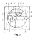
- the sawing device shown schematically in FIG. 1 in a side view initially has a support frame 1, in which a base plate 2 is mounted so that it can be turned through 180 °.
- the base plate 2 has one on each side Workpiece support surface 3, namely on one side for a cross-cut and miter saw function, as shown in FIG. 1, and on the other side for a table saw function.
- a saw unit 4 is attached to the base plate 2 on one side.
- the saw unit 4 has a saw blade 5 which is mounted on a shaft 6 and is driven by a drive motor 7 for sawing.
- the saw unit 4 can first be pivoted relative to the base plate 2 about a first pivot axis 8 running parallel to the shaft 6 of the saw blade 5.
- the pivot axis 8 is part of a pivot bearing block 9.
- the pivot bearing block 9 in turn can be pivoted about a second pivot axis 10 that is perpendicular to the first pivot axis 8 and runs parallel to the workpiece support surface 3.
- the second pivot axis 10 is not physically present in the exemplary embodiment shown, but is only present virtually as the center of a link guide 11.
- the saw unit 4 can be pivoted up and down in the cross-cut saw position between a Rh position distant from the base plate 2 and a saw position close to the base plate 2.
- the chop saw position is shown in Fig. 1. In the table saw position which can be adjusted when the base plate 2 is turned relative to the chop saw position, the saw blade 5 penetrates the base plate 2 from below, the saw unit 4 is located under the base plate 2.
- FIGS. 2 and 3 show the chop saw position, FIG. 5 the table saw position.
- a support device 12 can be seen in the figures. As is known per se, this is designed as a threaded spindle or more precisely as a threaded telescope.
- the saw unit 4 can be held by the support device 12 in the table saw position in the sawing position, that is to say with the saw blade 5 projecting upwards through the base plate 2. In the chop saw position shown in FIGS. 1 to 3, however, the support device 12 is ineffective.
- the support device 12 is supported at one end in FIG. 5 on the base plate 2 or on a part firmly connected thereto. 2 and 3, however, the support device 12 is supported at one end on the pivot bearing 9.
- the support device 12 is located on the side of the swivel bearing block 9 facing away from the saw unit 4, the threaded spindle also provided there, or the threaded telescope also provided there, runs essentially perpendicular to the workpiece support surface 3.
- the support device 12 is fixedly attached at one end in the longitudinal direction and that the other end 14 of the support device 12 is mounted in a connecting block 15 so as to be longitudinally displaceable but lockable in a specific displacement position. It is therefore essential that the support device 12 is connected to the respective bearing element essentially at both ends 13, 14 in each position. So it does not perform any uncontrolled movements in the chop saw position when the saw unit 4 is pivoted up and down, but only slides with the corresponding end 14 in the connecting block 15. For the table saw position, the saw unit 4 is brought into the corresponding saw position and the support device 12 is in the terminal block 5 locked. The height of the saw unit 4, that is to say the effective cutting height of the saw blade 5, can now be adjusted by the support device 12.
- connection block 15 is designed as a sliding guide with a spring catch 16 or screw catch arranged transversely.
- the spring catch 16 can be seen very well, details of which will be explained further below.
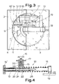
- one end 14 of the support device 12, in particular with the connection block 15, is arranged in the interior of the saw unit 4, near the shaft 6 of the saw blade 5, and that the support device 12 is located there extends obliquely to the rear or also essentially horizontally beyond the pivot bearing block 9 and an actuating handle 16 ', in particular a rotary knob of the threaded spindle, is arranged at the end 13 projecting rearward beyond the pivot bearing block 9.
- the saw unit 4 initially has, in addition to a pivot arm 17 carrying the saw blade 5, a further auxiliary pivot arm which engages on a protective hood 18 for the saw blade 5 19 has.
- a parallelogram mounting is known per se for sawing devices of the type in question or a similar type.
- This parallelogram construction is used here to a particular degree, namely in the exemplary embodiment according to FIG. 3 in that the support device 12 is arranged between the swivel arm 17 and the auxiliary bearing arm 19.
- connection block 15 is arranged on the swivel arm 17, but, as said, it could also be located directly on the swivel bearing block 9.
- the construction shown contributes to the fact that the support device 12 on the saw unit 4 is in a particularly favorable position.
- the actuating handle 16 ' projects essentially freely to the rear from the saw unit 4, it can be easily gripped and rotated, as is also necessary for the height adjustment of the saw unit 4 in the table saw position.
- the support device 12 clearly shown there is in the form of a threaded telescope.
- the actuating handle 16 ′ constructed as a rotary knob of the threaded spindle, which is coupled to the bearing 21 on the auxiliary swivel arm 19 via a threaded shaft 20.
- the connection block 15 carries a lateral sliding guide 22, in which the spring catch is slidably mounted here with its own actuating knob 23.
- the spring catch 16 is provided with a lateral pin 24 which can be inserted into a pin receptacle 25 when the actuating knob 23 is rotated through 90 °. Thereby the spring catch 16 is locked in its disengaged position. Then the support device 12 can be moved longitudinally in the connection block 15.
- a compression spring 26 is also provided, which always tries to push the support device 12 into the longest possible position, so that there are clear starting conditions.
- the support device 12 is fixedly and captively attached at one end 13 in the longitudinal direction.
- the other end 14 of the support device 12 is removably attached to the drive motor 7.
- mount the end 14 of the support device 12 in a terminal block 15 so as to be longitudinally displaceable but lockable in a certain displacement position.
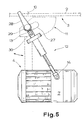
- Fig. 5 also shows very clearly how here at a distance from the second pivot axis 10 with the base plate 2 fixedly connected a part-arc-shaped elongated hole 27 in the pivot bearing block 9, which is only indicated by dashed lines, penetrating locking spindle 28, identified by its corresponding rocker arm , is attached, which serves to lock the saw unit 4 in any inclination positions. This is also known from the prior art.
- the support device 12 here the threaded telescopic spindle shown, in the table saw position shown in FIG. 5 with the saw unit 4 not inclined laterally, as shown, from the base plate 2 to the saw unit 4 to one side sloping. This is associated with the "erection effect" discussed in the introduction to this alternative.
- the rest is that the angle of inclination of the support device 12 is approximately 30 ° at most, which is matched to the maximum angle of inclination of the saw unit 4 of approximately 45 °. This results in the smallest positional deviations of the saw blade 5 in the table saw position on average.
- Fig. 5 can also be seen that the fixed end 13 of the support device 12 is not attached to the base plate 2 in the plane of the workpiece support surface 3, but at a distance from the workpiece support surface 3, namely at the level of the locking spindle 28 is structurally more expedient, since otherwise the support device 12 would also have to be guided past the locking spindle 28 or its rocker arm, which would require somewhat more complicated constructions of the support device 12.
- a ball bearing on the base plate 2 which can be tilted on all sides is also expedient.
- a bearing sleeve 29 is attached to the mounting spindle 28 for mounting the end 13 of the support device 12, on which the end 13 of the support device 12 is articulated on a special tab 30.
Abstract
Description
Die Erfindung betrifft eine Sägeeinrichtung mit den Merkmalen des Oberbegriffes von Anspruch 1.The invention relates to a sawing device with the features of the preamble of claim 1.
Die bekannte Sägeeinrichtung, von der die Erfindung ausgeht (EP-B 0 058 775), ist eine kombinierte Kapp-, Gehrungs- und Tischsäge mit einer in einem Traggestell um 180° wendbar gelagerten Grundplatte. In der einen Position befindet sich das Sägeaggregat oberhalb der Grundplatte, es handelt sich hier um die sogenannte Kappsägeposition. In der Kappsägeposition muß das Sägeaggregat bestimmungsgemäß aufwärts und abwärts geschwenkt werden können. In um 180° geschwenkter Stellung der Grundplatte befindet sich das Sägeaggregat unterhalb der Grundplatte. Es muß hier ganz nahe an die Grundplatte herangeschwenkt sein, da das Sägeblatt in dieser Tischsägeposition die Grundplatte nach oben hin durchsetzen muß. Gesägt wird auf der Werkstückauflagefläche auf der Oberseite der Grundplatte mit dem von unten her nach oben durchragenden Sägeblatt. Um das Sägeaggregat in der Tischsägeposition in einer bestimmten Höhe zu fixieren, ist die im Anspruch erwähnte Stützvorrichtung vorgesehen. Diese ist meist eine Gewindespindel oder ein Gewindeteleskop, so daß bei eingeklinkter Stützvorrichtung die Position des Sägeaggregates in der Höhe auch eingestellt werden kann. Dadurch kann dann die Schnitttiefe des Sägeblattes oberhalb der Grundplatte eingestellt werden.The known sawing device, from which the invention is based (EP-
Bei dem zuvor erläuterten, bekannten Stand der Technik befindet sich die Stützvorrichtung auf der vom Sägeaggregat abgewandten Seite des Schwenklagerblockes zwischen dem Anschlußpunkt am Sägeaggregat und einer vom Schwenklagerblock nach hinten abragenden Lagergabel. Für die Kappsägeposition wird die Gewindespindel, die hier die Stützvorrichtung bildet, einfach aus einer Lagerstelle herausgenommen und nach oben weggeklappt. Ggf. kann die Stützvorrichtung auch gänzlich abgenommen werden. In beiden Fällen kann es in der Praxis zu Problemen kommen, dergestalt nämlich, daß die Gewindespindel unbeabsichtigt verhakt oder, bei vollständig abgenommener Gewindespindel, verloren geht.In the previously described known prior art, the support device is located on the side of the pivot bearing block facing away from the saw unit between the connection point on the saw unit and a bearing fork projecting rearward from the pivot bearing block. For the cross-cut saw position, the threaded spindle, which forms the support device here, is simply removed from a bearing point and folded upwards. Possibly. the support device can also be completely removed. In both cases problems can arise in practice, such that the threaded spindle is unintentionally hooked or, if the threaded spindle is completely removed, is lost.
Im übrigen ist die zuvor erläuterte, bekannte Konstruktion auch noch deshalb nachteilig, weil die Gewindespindel in der Tischsägeposition im wesentlichen senkrecht zur Grundplatte verläuft und daher die Drehbewegung der Gewindespindel zum Zwecke der Höheneinstellung des Sägeaggregates handhabungstechnisch etwas schwierig zu bewerkstelligen ist.In addition, the previously described, known construction is also disadvantageous because the threaded spindle in the table saw position is substantially perpendicular to the base plate and therefore the rotational movement of the threaded spindle for the purpose of adjusting the height of the saw unit is somewhat difficult to handle in terms of handling.
Eine Sägeeinrichtung der zuvor erläuterten Art, jedoch ohne eine zweite Schwenkachse, also ohne die Ausgestaltung für Shifterschnitte, jedoch ebenfalls mit einer Gewindespindel als Stützvorrichtung, die dort direkt zwischen der wendbar gelagerten Grundplatte und dem Sägeaggregat angeordnet ist, ist im übrigen seit Jahrzehnten bekannt (DE-C 1 628 992). Beläßt man es bei dieser direkten Anordnung der Stützvorrichtung und rüstet diese Sägeeinrichtung aber gleichwohl mit einer zweiten Schwenkachse für Shifterschnitte aus, so verändern sich beim Schwenken um die zweite Schwenkachse die wirksamen Längen der Anbringung des Sägeaggregates an der Grundplatte einerseits und der Stützvorrichtung andererseits relativ zueinander. Von der senkrechten Mittelstellung ausgehend führt dadurch allein die seitliche Schwenkung des Sägeaggregates in Tischsägeposition dazu, daß das Sägeblatt in geneigter Stellung ein wenig abgesenkt ist, da die wirksame Länge der Stützvorrichtung durch die seitliche Schwenkung verringert worden ist (siehe z. B. US-A 2 851 068).A sawing device of the type explained above, but without a second pivot axis, i.e. without the design for shifter cuts, but also with a threaded spindle as a support device, which is arranged there directly between the reversible base plate and the saw unit, has been known for decades otherwise (DE -C 1 628 992). If you leave it with this direct arrangement of the support device and equip this sawing device with a second pivot axis for shifter cuts, the effective lengths of the attachment of the saw unit on the base plate on the one hand and the support device on the other hand change relative to one another when pivoting about the second pivot axis. Starting from the vertical central position, the lateral pivoting of the saw unit in the table saw position alone means that the saw blade is slightly lowered in the inclined position, since the effective length of the support device has been reduced by the lateral pivoting (see, for example, US-A 2 851 068).
Die zuvor erläuterte Problematik, die als unlösbar angesehen worden ist, hat dann dazu geführt, daß man von einer direkten Lagerung der Stützvorrichtung an der Grundplatte bzw. an einem damit fest verbundenen Teil gänzlich abgegangen ist. Man hat vielmehr das bisher an der Grundplatte angebrachte Ende der Stützvorrichtung bei der eingangs erläuterten Sägeeinrichtung, von der die Erfindung ausgeht (EP-B 0 058 775) in den um die zweite Schwenkachse schwenkbaren Schwenklagerblock selbst verlagert. Es liegt auf der Hand, daß mit dieser relative Längenänderungen aufgrund der Schwenkung des Sägeaggregates um die zweite Schwenkachse nicht mehr auftreten können, da der Fußpunkt der Stützvorrichtung ja in gleicher Weise wie das Sägeaggregat mit um die zweite Schwenkachse (und eben nicht um eine andere, davon beabstandete Schwenkachse) geschwenkt wird.The problem explained above, which was considered to be unsolvable, has led to the fact that a direct mounting of the support device on the base plate or on a part firmly connected therewith has been completely avoided. Rather, the end of the support device previously attached to the base plate in the saw device explained at the beginning, from which the invention is based (EP-
Der Erfindung liegt die Aufgabe zugrunde, die eingangs erläuterte, bekannte Sägeeinrichtung so auszugestalten und weiterzubilden, daß hinsichtlich der Stützvorrichtung eine wesentlich verbesserte Konstruktion vorliegt.The object of the invention is to design and develop the known sawing device explained at the outset in such a way that there is a substantially improved construction with respect to the support device.
Die zuvor aufgezeigte Aufgabe ist in einer ersten Alternative durch die Merkmale des kennzeichnenden Teils von Anspruch 1 gelöst.The object presented above is achieved in a first alternative by the features of the characterizing part of claim 1.
Mit der erfindungsgemäßen Konstruktion befindet sich die Stützvorrichtung, insbesondere die Gewindespindel, stets an beiden Enden in Verbindung mit dem jeweiligen lagernden Element. Dabei ist erkannt worden, daß die Schwenkbeweglichkeit des Sägeaggregates, die in Kappsägeposition erforderlich ist, bei der üblicherweise verwirklichten Drehbarkeit der Lagerung an den beiden Enden der Stützvorrichtung lediglich eine Längsverschiebbarkeit an einem Ende erfordert. Von dieser Erkenntnis ausgehend ist dann für die Kappsägeposition die Längsverschiebbarkeit im Anschlußblock vorgesehen worden, der dann in der Tischsägeposition die Arretierung der Stützvorrichtung im Anschlußblock entspricht. Die Stützvorrichtung, insbesondere als eine Gewindespindel, kann so weder ungewollt und unkontrolliert in eine Blockierstellung geraten, noch kann sie verloren gehen. Es ist lediglich darauf zu achten, daß die Arretierung im Anschlußblock nicht ohne weiteres einzurasten vermag. Dafür gibt es aber eine Reihe von technischen Möglichkeiten.With the construction according to the invention, the support device, in particular the threaded spindle, is always at both ends in connection with the respective bearing element. It has been recognized that the pivoting mobility of the saw unit, which is required in the cross-cut saw position, only requires a longitudinal displaceability at one end in the case of the rotatability of the bearing at the two ends of the supporting device which is usually implemented. Based on this knowledge, the longitudinal displacement in the connection block was then provided for the chop saw position, which then corresponds to the locking of the support device in the connection block in the table saw position. The support device, in particular as a threaded spindle, can neither get into a blocking position unintentionally and uncontrolled, nor can it be lost. It is only necessary to ensure that the locking device in the connection block is not able to snap in easily. However, there are a number of technical options for this.
Weiter bevorzugte Ausgestaltungen sind Gegenstand der Ansprüche 2 bis 7.Further preferred embodiments are the subject of
Die zuvor aufgezeigte Aufgabe ist in einer weiteren Lehre durch die Merkmale des kennzeichnenden Teils von Anspruch 8 gelöst. Die dort beschriebene Ausrichtung der Stützvorrichtung, insbesondere also der Gewindespindel, führt dazu, daß sich die Gewindespindel in dem gleichen Maße "?aufrichtet", in dem das Sägeaggregat um die zweite Schwenkachse aus der senkrechten Mittelebene herausgeschwenkt wird. Die sich "aufrichtende" Stützvorrichtung verlängert ihre wirksame Länge gerade in dem Maße, in dem sie durch die seitliche Schwenkung des Sägeaggregates wiederum auch verkürzt wird. Zwei gegenläufige Effekte kompensieren hier einander also weitgehend, wenn auch natürlich nicht absolut vollständig. Diese Kompensation reicht jedenfalls aus, um in der Praxis eine ausreichende Präzision der beanspruchten Sägeeinrichtung zu erreichen, also zu erreichen, daß die durch relative Längenänderungen verursachten Lageänderungen des Sägeblattes in Tischsägeposition praktisch nicht mehr störend ins Gewicht fallen.The object presented above is achieved in a further teaching by the features of the characterizing part of
Eine weiter bevorzugte Ausgestaltung findet sich in Anspruch 9.A further preferred embodiment can be found in
Eine weiter bevorzugte Ausgestaltung der zuvor erläuterten Lehre, der aber auch selbständige Bedeutung zukommt, findet sich schließlich in Anspruch 10.A further preferred embodiment of the teaching explained above, but which is also of independent importance, can finally be found in
Im folgenden wird die Erfindung anhand einer lediglich Ausführungsbeispiele darstellenden Zeichnung näher erläutert. In der Zeichnung zeigt
- Fig. 1
- in einer perspektivischen Darstellung eine Sägeeinrichtung der erfindungsgemäßen Art,
- Fig. 2
- in einer Draufsicht, schematisch, die Lagerung des Sägeaggregates der Sägeeinrichtung aus Fig. 1,
- Fig. 3
- in Fig. 2 entsprechender Darstellung ein abgewandeltes Ausführungsbeispiel einer solchen Sägeeinrichtung,
- Fig. 4
- die Stützvorrichtung der Sägeeinrichtung aus den Fig. 2 und 3 in vergrößerter Darstellung, teilweise geschnitten, und
- Fig. 5
- in einer stark schematisierten Ansicht von der Rückseite aus und in Tischsägeposition ein weiteres Ausführungsbeispiel einer Sägeeinrichtung gemäß Fig. 1.
- Fig. 1
- in a perspective view a sawing device of the type according to the invention,
- Fig. 2
- in a plan view, schematically, the storage of the saw unit of the sawing device from FIG. 1,
- Fig. 3
- 2 corresponding representation a modified embodiment of such a sawing device,
- Fig. 4
- the support device of the sawing device from FIGS. 2 and 3 in an enlarged view, partly in section, and
- Fig. 5
- A further embodiment of a sawing device according to FIG. 1 in a highly schematic view from the rear and in the table saw position.
Die in Fig. 1 in einer Seitenansicht schematisch dargestellte Sägeeinrichtung weist zunächst ein Traggestell 1 auf, in dem eine Grundplatte 2 um 180° wendbar gelagert ist. Die Grundplatte 2 hat auf beiden Seiten jeweils eine Werkstückauflagefläche 3, nämlich auf einer Seite für eine Kapp- und Gehrungssägefunktion, wie in Fig. 1 dargestellt, und auf der anderen Seite für eine Tischsägefunktion. Auf einer Seite ist an der Grundplatte 2 ein Sägeaggregat 4 angebracht. Das Sägeaggregat 4 weist ein Sägeblatt 5 auf, das auf einer Welle 6 gelagert ist und von einem Antriebsmotor 7 zum Sägen angetrieben wird. Das Sägeaggregat 4 kann zunächst gegenüber der Grundplatte 2 um eine parallel zur Welle 6 des Sägeblattes 5 verlaufende erste Schwenkachse 8 geschwenkt werden. Die Schwenkachse 8 ist Teil eines Schwenklagerblockes 9. Der Schwenklagerblock 9 seinerseits ist um eine zur ersten Schwenkachse 8 senkrechte, parallel zur Werkstückauflagefläche 3 verlaufende zweite Schwenkachse 10 schwenkbar. Die zweite Schwenkachse 10 ist im dargestellten Ausführungsbeispiel nicht körperlich vorhanden, sondern ist lediglich virtuell als Zentrum einer Kulissenführung 11 vorhanden. Das Sägeaggregat 4 ist in der Kappsägeposition zwischen einer von der Grundplatte 2 entfernten Rhestellung und einer der Grundplatte 2 nahen Sägestellung auf und ab schwenkbar. Die Kappsägeposition ist in Fig. 1 dargestellt. In der bei gegenüber der Kappsägeposition gewendeter Grundplatte 2 einstellbaren Tischsägeposition durchdringt das Sägeblatt 5 die Grundplatte 2 von unten her, das Sägeaggregat 4 befindet sich unter der Grundplatte 2. Fig. 2 und 3 zeigen die Kappsägeposition, Fig. 5 die Tischsägeposition.The sawing device shown schematically in FIG. 1 in a side view initially has a support frame 1, in which a
In den Figuren erkennt man eine Stützvorrichtung 12. Diese ist, wie an sich bekannt, als Gewindespindel bzw. hier genauer gesagt als Gewindeteleskop ausgeführt. Das Sägeaggregat 4 kann durch die Stützvorrichtung 12 in Tischsägeposition in der Sägestellung, also mit nach oben durch die Grundplatte 2 hindurchragendem Sägeblatt 5 gehalten werden. In der in Fig. 1 bis 3 dargestellten Kappsägeposition ist die Stützvorrichtung 12 allerdings unwirksam. Die Stützvorrichtung 12 ist in Fig. 5 einenends an der Grundplatte 2 gelagert bzw. an einem damit fest verbundenen Teil. In den Fig. 2 und 3 hingegen ist die Stützvorrichtung 12 einenends an der Schwenklagerung 9 gelagert.A
Im Stand der Technik befindet sich die Stützvorrichtung 12 auf der vom Sägeaggregat 4 abgewandten Seite des Schwenklagerblockes 9, die auch dort vorgesehene Gewindespindel bzw. das auch dort vorgesehene Gewindeteleskop verläuft im wesentlichen senkrecht zur Werkstückauflagefläche 3.In the prior art, the
In dem dargestellten, erfindungsgemäßen Ausführungsbeispiel gilt nun hingegen, daß die Stützvorrichtung 12 an einem Ende in Längsrichtung fest angebracht ist und daß das andere Ende 14 der Stützvorrichtung 12 in einem Anschlußblock 15 längsverschiebbar, aber in einer bestimmten Verschiebestellung arretierbar, gelagert ist. Wesentlich ist also, daß die Stützvorrichtung 12 in jeder Stellung im wesentlichen an beiden Enden 13, 14 mit dem jeweiligen lagernden Element verbunden ist. Sie führt also auch in der Kappsägeposition beim Auf- und Abschwenken des Sägeaggregats 4 keine unkontrollierten Bewegungen aus, sondern gleitet nur mit dem entsprechenden Ende 14 im Anschlußblock 15. Für die Tischsägeposition wird das Sägeaggregat 4 in die entsprechende Sägestellung gebracht und die Stützvorrichtung 12 wird in dem Anschlußblock 5 arretiert. Dabei läßt sich nun die Höhe des Sägeaggregates 4, also die wirksame Schnitthöhe des Sägeblattes 5 durch die Stützvorrichtung 12 einstellen.In the illustrated exemplary embodiment according to the invention, however, it now applies that the
Fig. 4 macht deutlich, daß der Anschlußblock 15 als Gleitführung mit quer angeordneter Federraste 16 oder Schraubraste ausgeführt ist. Im hier dargestellten Ausführungsbeispiel erkennt man sehr gut die Federraste 16, zu der weiter unten noch nähere Details ausgeführt werden.Fig. 4 makes it clear that the
Aus Fig. 2 und Fig. 3 läßt sich erkennen, daß ein Ende 14 der Stützvorrichtung 12, insbesondere mit dem Anschlußblock 15, im Inneren des Sägeaggregates 4, nahe der Welle 6 des Sägeblattes 5, angeordnet ist und daß sich die Stützvorrichtung 12 von dort aus schräg nach hinten oder auch im wesentlichen horizontal über den Schwenklagerblock 9 hinaus erstreckt und am nach hinten über den Schwenklagerblock 9 hinausragenden Ende 13 eine Betätigungshandhabe 16', insbesondere ein Drehknauf der Gewindespindel, angeordnet ist.From Fig. 2 and Fig. 3 it can be seen that one
Während in Fig. 2 die Stützvorrichtung 12 zwischen dem Sägeaggregat 4 selbst und dem Schwenklagerblock 9 angeordnet ist, ist in Fig. 3 noch etwas besonderes zu erkennen. Für alle Figuren gilt dabei zunächst, daß das Sägeaggregat 4 zusätzlich zu einem das Sägeblatt 5 tragenden Schwenkarm 17 noch einen weiteren, an einer Schutzhaube 18 für das Sägeblatt 5 angreifenden Hilfsschwenkarm 19 aufweist. Eine derartige Parallelogrammlagerung ist an sich für Sägeeinrichtungen der in Rede stehenden oder einer ähnlichen Art bekannt. Diese Parallelogrammkonstruktion wird hier in besonderem Maße genutzt, nämlich bei dem Ausführungsbeispiel gemäß Fig. 3 dadurch, daß die Stützvorrichtung 12 zwischen dem Schwenkarm 17 und dem Hilfslagerarm 19 angeordnet ist. Sie könnte auch zwischen dem Hilfsschwenkarm 19 und dem Schwenklagerblock 9 angeordnet sein oder in ähnlich wirkender Anordnung, wie an sich aus dem Stand der Technik bekannt (DE-C 1 628 992). Im hier dargestellten Ausführungsbeispiel ist der Anschlußblock 15 am Schwenkarm 17 angeordnet, er könnte sich aber, wie gesagt, auch direkt an dem Schwenklagerblock 9 befinden. Die dargestellte Konstruktion trägt dazu bei, daß sich die Stützvorrichtung 12 am Sägeaggregat 4 in einer besonders günstigen Lage befindet. Die Betätigungshandhabe 16' ragt nämlich im wesentlichen frei nach hinten vom Sägeaggregat 4 ab, sie kann leicht erfaßt und gedreht werden, wie das für die Höheneinstellung des Sägeaggregates 4 in Tischsägeposition auch erforderlich ist.While the
Von besonderem Vorteil ist bei dieser Anordnung, daß auch ein Arretierknebel für die Schwenklagerung des Schwenklagerblockes 9 selbst zumeist an der gleichen Stelle bzw. in unmittelbarer Nähe zu finden ist. Die Elemente zur Höheneinstellung und zur seitlichen Neigungseinstellung des Sägeaggregates 4 befinden sich konstruktiv also nahe beieinander. Bedienungstechnisch ist das von großem Vorteil.It is particularly advantageous with this arrangement that a locking toggle for the pivot mounting of the
Zu Fig. 4 ist im Detail noch zu erläutern, daß die dort deutlich dargestellte Stützvorrichtung 12 in Form eines Gewindeteleskops ausgeführt ist. Man erkennt die als Drehknauf der Gewindespindel konstruierte Betätigungshandhabe 16', die über einen Gewindeschaft 20 mit dem Lager 21 am Hilfsschwenkarm 19 gekuppelt ist. Der Anschlußblock 15 trägt eine seitliche Gleitführung 22, in der hier die Federraste mit einem eigenen Betätigungsknauf 23 gleitend gelagert ist. Die Federraste 16 ist im dargestellten Ausführungsbeispiel mit einem seitlichen Zapfen 24 versehen, der in eine Zapfenaufnahme 25 einführbar ist, wenn man den Betätigungsknauf 23 um 90° dreht. Dadurch wird die Federraste 16 in ihrer ausgerasteten Position arretiert. Dann kann die Stützvorrichtung 12 in dem Anschlußblock 15 längsverschoben werden. Im übrigen ist noch eine Druckfeder 26 vorgesehen, die die Stützvorrichtung 12 immer in die längstmögliche Position zu drücken versucht, so daß eindeutige Ausgangsverhältnisse gegeben sind.4 is to be explained in detail that the
Im in Fig. 5 dargestellten Ausführungsbeispiel ist die Stützvorrichtung 12 an ihrem einen Ende 13 in Längsrichtung fest und unverlierbar angebracht. Das andere Ende 14 der Stützvorrichtung 12 ist am Antriebsmotor 7 abnehmbar angebracht. Grundsätzlich wäre es möglich, auch hier das Ende 14 der Stützvorrichtung 12 in einem Anschlußblock 15 längsverschiebbar, aber in einer bestimmten Verschiebestellung arrierbar, zu lagern.In the exemplary embodiment shown in FIG. 5, the
Fig. 5 läßt weiter sehr gut erkennen, wie hier mit Abstand von der zweiten Schwenkachse 10 mit der Grundplatte 2 lagefest verbunden eine ein teilkreisbogenförmiges Langloch 27 in dem Schwenklagerblock 9, der hier lediglich gestrichelt angedeutet ist, durchsetzende Feststellspindel 28, indentifiziert durch ihren entsprechenden Kippspannhebel, angebracht ist, die zur Arretierung des Sägeaggregates 4 in beliebigen Neigungsstellungen dient. Auch das ist aus dem Stand der Technik bekannt.Fig. 5 also shows very clearly how here at a distance from the
Für diese Konstruktion ist nun wesentlich, daß die Stützvorrichtung 12, hier also die dargestellte Gewinde-Teleskopspindel, in der in Fig. 5 dargestellten Tischsägeposition bei nicht seitlich geneigtem Sägeaggregat 4, wie dargestellt, von der Grundplatte 2 aus zum Sägeaggregat 4 zur einen Seite hin abfallend verläuft. Damit ist der in der Beschreibungseinleitung zu dieser Alternative erörterte "Aufrichteffekt" verbunden.For this construction, it is essential that the
Im in Fig. 5 dargestellten Ausführungsbeispiel gilt im übrigen, daß der Neigungswinkel der Stützvorrichtung 12 etwa maximal 30° beträgt, was auf den maximalen Neigungswinkel des Sägeaggregats 4 von ca. 45° abgestimmt ist. Dadurch ergeben sich im Mittel die geringsten Lageabweichungen des Sägeblattes 5 in Tischsägeposition.In the exemplary embodiment shown in FIG. 5, the rest is that the angle of inclination of the
Fig. 5 läßt im übrigen gut erkennen, daß hier das feste Ende 13 der Stützvorrichtung 12, nicht etwa in der Ebene der Werkstückauflagefläche 3 an der Grundplatte 2 angebracht ist, sondern mit Abstand von der Werkstückauflagefläche 3, nämlich in Höhe der Feststellspindel 28. Das ist konstruktiv zweckmäßiger, da sonst die Stützvorrichtung 12 an der Feststellspindel 28 bzw. deren Kippspannhebel auch noch vorbeigeführt werden müßte, was etwas kompliziertere Konstruktionen der Stützvorrichtung 12 erfordern würde. Im Grundsatz gilt aber, daß in an sich bekannter Weise auch beispielsweise eine allseits kippbewegliche Kugellagerung an der Grundplatte 2 zweckmäßig ist.Fig. 5 can also be seen that the
Im dargestellten Ausführungsbeispiel gilt nun, daß zur Lagerung des Endes 13 der Stützvorrichtung 12 auf der Feststellspindel 28 eine Lagerhülse 29 angebracht ist, an der das Ende 13 der Stützvorrichtung 12 an einer speziellen Lasche 30 angelenkt ist.In the illustrated embodiment, it is now the case that a bearing
Claims (10)
Applications Claiming Priority (4)
| Application Number | Priority Date | Filing Date | Title |
|---|---|---|---|
| DE19904010456 DE4010456A1 (en) | 1990-03-31 | 1990-03-31 | Combined cut=off and table type circular saw - has telescopic strut to lock vertical traverse of saw unit when inverted in table saw mode |
| DE4010456 | 1990-03-31 | ||
| DE9005300U DE9005300U1 (en) | 1990-05-10 | 1990-05-10 | |
| DE9005300U | 1990-05-10 |
Publications (3)
| Publication Number | Publication Date |
|---|---|
| EP0450408A2 true EP0450408A2 (en) | 1991-10-09 |
| EP0450408A3 EP0450408A3 (en) | 1991-11-06 |
| EP0450408B1 EP0450408B1 (en) | 1995-08-16 |
Family
ID=25891767
Family Applications (1)
| Application Number | Title | Priority Date | Filing Date |
|---|---|---|---|
| EP91104372A Expired - Lifetime EP0450408B1 (en) | 1990-03-31 | 1991-03-20 | Sawing device having a base plate able to pivot over 180 degrees |
Country Status (4)
| Country | Link |
|---|---|
| EP (1) | EP0450408B1 (en) |
| AT (1) | ATE126469T1 (en) |
| DE (1) | DE59106242D1 (en) |
| ES (1) | ES2075239T3 (en) |
Cited By (3)
| Publication number | Priority date | Publication date | Assignee | Title |
|---|---|---|---|---|
| EP0633105A1 (en) * | 1993-07-08 | 1995-01-11 | Black & Decker Inc. | Chop/table saw with parallelogram arrangement |
| US5787779A (en) * | 1993-07-08 | 1998-08-04 | Black & Decker Inc. | Chop/table saw arrangement |
| TWI393600B (en) * | 2004-07-13 | 2013-04-21 | Black & Decker Inc | Miter lock assembly for miter saws |
Citations (7)
| Publication number | Priority date | Publication date | Assignee | Title |
|---|---|---|---|---|
| US2496716A (en) * | 1946-05-07 | 1950-02-07 | John W Hanna | Swinging frame portable saw |
| DE1920062A1 (en) * | 1969-04-19 | 1970-10-22 | Mey Kg Maschf Mafell | Device for adjusting the height of circular saws |
| DE1628992A1 (en) * | 1968-01-03 | 1971-11-11 | Lutz Kg Maschf Eugen | Combined table and miter saw |
| US3827325A (en) * | 1972-04-04 | 1974-08-06 | Gang Nail Truss Co Inc | Trim saw mounting bracket assembly |
| EP0058775A2 (en) * | 1981-02-19 | 1982-09-01 | Eugen Lutz GmbH & Co. Maschinenfabrik | Combined table and mitre saw |
| FR2511924A1 (en) * | 1981-08-28 | 1983-03-04 | Festo Maschf Stoll G | CIRCULAR SAW DEVICE |
| DE9005300U1 (en) * | 1990-05-10 | 1990-07-12 | Elektra-Beckum Lubitz & Co, 4470 Meppen, De |
-
1991
- 1991-03-20 AT AT91104372T patent/ATE126469T1/en not_active IP Right Cessation
- 1991-03-20 DE DE59106242T patent/DE59106242D1/en not_active Expired - Fee Related
- 1991-03-20 EP EP91104372A patent/EP0450408B1/en not_active Expired - Lifetime
- 1991-03-20 ES ES91104372T patent/ES2075239T3/en not_active Expired - Lifetime
Patent Citations (7)
| Publication number | Priority date | Publication date | Assignee | Title |
|---|---|---|---|---|
| US2496716A (en) * | 1946-05-07 | 1950-02-07 | John W Hanna | Swinging frame portable saw |
| DE1628992A1 (en) * | 1968-01-03 | 1971-11-11 | Lutz Kg Maschf Eugen | Combined table and miter saw |
| DE1920062A1 (en) * | 1969-04-19 | 1970-10-22 | Mey Kg Maschf Mafell | Device for adjusting the height of circular saws |
| US3827325A (en) * | 1972-04-04 | 1974-08-06 | Gang Nail Truss Co Inc | Trim saw mounting bracket assembly |
| EP0058775A2 (en) * | 1981-02-19 | 1982-09-01 | Eugen Lutz GmbH & Co. Maschinenfabrik | Combined table and mitre saw |
| FR2511924A1 (en) * | 1981-08-28 | 1983-03-04 | Festo Maschf Stoll G | CIRCULAR SAW DEVICE |
| DE9005300U1 (en) * | 1990-05-10 | 1990-07-12 | Elektra-Beckum Lubitz & Co, 4470 Meppen, De |
Cited By (4)
| Publication number | Priority date | Publication date | Assignee | Title |
|---|---|---|---|---|
| EP0633105A1 (en) * | 1993-07-08 | 1995-01-11 | Black & Decker Inc. | Chop/table saw with parallelogram arrangement |
| US5513548A (en) * | 1993-07-08 | 1996-05-07 | Black & Decker Inc. | Chop/table saw with parallelogram arrangement |
| US5787779A (en) * | 1993-07-08 | 1998-08-04 | Black & Decker Inc. | Chop/table saw arrangement |
| TWI393600B (en) * | 2004-07-13 | 2013-04-21 | Black & Decker Inc | Miter lock assembly for miter saws |
Also Published As
| Publication number | Publication date |
|---|---|
| ES2075239T3 (en) | 1995-10-01 |
| EP0450408A3 (en) | 1991-11-06 |
| EP0450408B1 (en) | 1995-08-16 |
| ATE126469T1 (en) | 1995-09-15 |
| DE59106242D1 (en) | 1995-09-21 |
Similar Documents
| Publication | Publication Date | Title |
|---|---|---|
| DE4027316C2 (en) | Device for adjusting the position of a circular saw blade | |
| DE2813825A1 (en) | MOTOR DRIVEN TABLE SAW | |
| EP0014869B1 (en) | Circular saw | |
| DE4336662A1 (en) | Scissor lift table | |
| EP0598248A1 (en) | Hand-operated circular saw with electric motor drive | |
| DE3736757C1 (en) | Table milling device | |
| EP0450408B1 (en) | Sawing device having a base plate able to pivot over 180 degrees | |
| DE4424615B4 (en) | Under-table miter saw | |
| EP0450400A1 (en) | Sawing device with pivoting protective hood attached to a saw unit | |
| DE19635527A1 (en) | Hand-held circular saw | |
| DE4004705A1 (en) | Bench-mounted circular saw - has saw blade and saw motor mounted on swinging arm to provide height adjustment | |
| DE4010456C2 (en) | ||
| DE2133308C3 (en) | Electric circular saw | |
| CH393716A (en) | Circular saw with a riving knife downstream of the saw blade | |
| DE3333169C2 (en) | ||
| DE7621408U1 (en) | WORKPIECE TABLE FOR ALTERNATIVE MOUNTING OF A CIRCULAR CIRCULAR SAW AS TABLE SAW OR CHAPPING SAW | |
| EP0481186B1 (en) | Oscillating mitre saw | |
| EP2355962B1 (en) | Cutting machine | |
| EP2186587B1 (en) | Mitre and mitre-box saw | |
| DE1810349A1 (en) | Self-aligning chuck, especially for jigsaws | |
| EP2250005B1 (en) | Circular saw with adjustable angle control | |
| DE19917535A1 (en) | Parallel stop device for format sawing machine | |
| EP2285519A1 (en) | Machine tool, especially circular saw bench | |
| EP0299155B1 (en) | Cold circular saw with a saw blade arm pivot transversely adjustable relative to the work piece conveying direction | |
| WO2009138272A1 (en) | Power tool, especially hand-held power tool |
Legal Events
| Date | Code | Title | Description |
|---|---|---|---|
| PUAI | Public reference made under article 153(3) epc to a published international application that has entered the european phase |
Free format text: ORIGINAL CODE: 0009012 |
|
| PUAL | Search report despatched |
Free format text: ORIGINAL CODE: 0009013 |
|
| AK | Designated contracting states |
Kind code of ref document: A2 Designated state(s): AT BE CH DE DK ES FR GB GR IT LI LU NL SE |
|
| AK | Designated contracting states |
Kind code of ref document: A3 Designated state(s): AT BE CH DE DK ES FR GB GR IT LI LU NL SE |
|
| 17P | Request for examination filed |
Effective date: 19920409 |
|
| RAP1 | Party data changed (applicant data changed or rights of an application transferred) |
Owner name: ELEKTRA BECKUM AKTIENGESELLSCHAFT |
|
| 17Q | First examination report despatched |
Effective date: 19940125 |
|
| GRAA | (expected) grant |
Free format text: ORIGINAL CODE: 0009210 |
|
| AK | Designated contracting states |
Kind code of ref document: B1 Designated state(s): AT BE CH DE DK ES FR GB GR IT LI LU NL SE |
|
| PG25 | Lapsed in a contracting state [announced via postgrant information from national office to epo] |
Ref country code: NL Free format text: LAPSE BECAUSE OF FAILURE TO SUBMIT A TRANSLATION OF THE DESCRIPTION OR TO PAY THE FEE WITHIN THE PRESCRIBED TIME-LIMIT Effective date: 19950816 Ref country code: GR Free format text: LAPSE BECAUSE OF FAILURE TO SUBMIT A TRANSLATION OF THE DESCRIPTION OR TO PAY THE FEE WITHIN THE PRESCRIBED TIME-LIMIT Effective date: 19950816 Ref country code: DK Effective date: 19950816 Ref country code: BE Effective date: 19950816 |
|
| REF | Corresponds to: |
Ref document number: 126469 Country of ref document: AT Date of ref document: 19950915 Kind code of ref document: T |
|
| REF | Corresponds to: |
Ref document number: 59106242 Country of ref document: DE Date of ref document: 19950921 |
|
| ET | Fr: translation filed | ||
| GBT | Gb: translation of ep patent filed (gb section 77(6)(a)/1977) |
Effective date: 19950830 |
|
| REG | Reference to a national code |
Ref country code: ES Ref legal event code: FG2A Ref document number: 2075239 Country of ref document: ES Kind code of ref document: T3 |
|
| ITF | It: translation for a ep patent filed |
Owner name: ING. A. GIAMBROCONO & C. S.R.L. |
|
| PG25 | Lapsed in a contracting state [announced via postgrant information from national office to epo] |
Ref country code: SE Effective date: 19951116 |
|
| NLV1 | Nl: lapsed or annulled due to failure to fulfill the requirements of art. 29p and 29m of the patents act | ||
| PG25 | Lapsed in a contracting state [announced via postgrant information from national office to epo] |
Ref country code: AT Effective date: 19960320 |
|
| PG25 | Lapsed in a contracting state [announced via postgrant information from national office to epo] |
Ref country code: LU Free format text: LAPSE BECAUSE OF NON-PAYMENT OF DUE FEES Effective date: 19960331 |
|
| PLBE | No opposition filed within time limit |
Free format text: ORIGINAL CODE: 0009261 |
|
| STAA | Information on the status of an ep patent application or granted ep patent |
Free format text: STATUS: NO OPPOSITION FILED WITHIN TIME LIMIT |
|
| 26N | No opposition filed | ||
| PGFP | Annual fee paid to national office [announced via postgrant information from national office to epo] |
Ref country code: GB Payment date: 19990322 Year of fee payment: 9 |
|
| PGFP | Annual fee paid to national office [announced via postgrant information from national office to epo] |
Ref country code: FR Payment date: 19990323 Year of fee payment: 9 |
|
| PGFP | Annual fee paid to national office [announced via postgrant information from national office to epo] |
Ref country code: ES Payment date: 19990329 Year of fee payment: 9 |
|
| PGFP | Annual fee paid to national office [announced via postgrant information from national office to epo] |
Ref country code: CH Payment date: 19990624 Year of fee payment: 9 |
|
| PG25 | Lapsed in a contracting state [announced via postgrant information from national office to epo] |
Ref country code: GB Free format text: LAPSE BECAUSE OF NON-PAYMENT OF DUE FEES Effective date: 20000320 |
|
| PG25 | Lapsed in a contracting state [announced via postgrant information from national office to epo] |
Ref country code: ES Free format text: LAPSE BECAUSE OF NON-PAYMENT OF DUE FEES Effective date: 20000321 |
|
| PG25 | Lapsed in a contracting state [announced via postgrant information from national office to epo] |
Ref country code: LI Free format text: LAPSE BECAUSE OF NON-PAYMENT OF DUE FEES Effective date: 20000331 Ref country code: CH Free format text: LAPSE BECAUSE OF NON-PAYMENT OF DUE FEES Effective date: 20000331 |
|
| PGFP | Annual fee paid to national office [announced via postgrant information from national office to epo] |
Ref country code: DE Payment date: 20000524 Year of fee payment: 10 |
|
| GBPC | Gb: european patent ceased through non-payment of renewal fee |
Effective date: 20000320 |
|
| REG | Reference to a national code |
Ref country code: CH Ref legal event code: PL |
|
| PG25 | Lapsed in a contracting state [announced via postgrant information from national office to epo] |
Ref country code: FR Free format text: LAPSE BECAUSE OF NON-PAYMENT OF DUE FEES Effective date: 20001130 |
|
| REG | Reference to a national code |
Ref country code: FR Ref legal event code: ST |
|
| REG | Reference to a national code |
Ref country code: ES Ref legal event code: FD2A Effective date: 20010910 |
|
| PG25 | Lapsed in a contracting state [announced via postgrant information from national office to epo] |
Ref country code: DE Free format text: LAPSE BECAUSE OF NON-PAYMENT OF DUE FEES Effective date: 20020101 |
|
| PG25 | Lapsed in a contracting state [announced via postgrant information from national office to epo] |
Ref country code: IT Free format text: LAPSE BECAUSE OF NON-PAYMENT OF DUE FEES;WARNING: LAPSES OF ITALIAN PATENTS WITH EFFECTIVE DATE BEFORE 2007 MAY HAVE OCCURRED AT ANY TIME BEFORE 2007. THE CORRECT EFFECTIVE DATE MAY BE DIFFERENT FROM THE ONE RECORDED. Effective date: 20050320 |