EP0450431A2 - Ultrasonic diagnostic system - Google Patents
Ultrasonic diagnostic system Download PDFInfo
- Publication number
- EP0450431A2 EP0450431A2 EP91104566A EP91104566A EP0450431A2 EP 0450431 A2 EP0450431 A2 EP 0450431A2 EP 91104566 A EP91104566 A EP 91104566A EP 91104566 A EP91104566 A EP 91104566A EP 0450431 A2 EP0450431 A2 EP 0450431A2
- Authority
- EP
- European Patent Office
- Prior art keywords
- catheter
- diagnostic system
- element array
- transducer element
- ultrasonic diagnostic
- Prior art date
- Legal status (The legal status is an assumption and is not a legal conclusion. Google has not performed a legal analysis and makes no representation as to the accuracy of the status listed.)
- Granted
Links
Images


Classifications
-
- A—HUMAN NECESSITIES
- A61—MEDICAL OR VETERINARY SCIENCE; HYGIENE
- A61B—DIAGNOSIS; SURGERY; IDENTIFICATION
- A61B8/00—Diagnosis using ultrasonic, sonic or infrasonic waves
-
- A—HUMAN NECESSITIES
- A61—MEDICAL OR VETERINARY SCIENCE; HYGIENE
- A61B—DIAGNOSIS; SURGERY; IDENTIFICATION
- A61B8/00—Diagnosis using ultrasonic, sonic or infrasonic waves
- A61B8/44—Constructional features of the ultrasonic, sonic or infrasonic diagnostic device
- A61B8/4483—Constructional features of the ultrasonic, sonic or infrasonic diagnostic device characterised by features of the ultrasound transducer
- A61B8/4494—Constructional features of the ultrasonic, sonic or infrasonic diagnostic device characterised by features of the ultrasound transducer characterised by the arrangement of the transducer elements
-
- G—PHYSICS
- G01—MEASURING; TESTING
- G01S—RADIO DIRECTION-FINDING; RADIO NAVIGATION; DETERMINING DISTANCE OR VELOCITY BY USE OF RADIO WAVES; LOCATING OR PRESENCE-DETECTING BY USE OF THE REFLECTION OR RERADIATION OF RADIO WAVES; ANALOGOUS ARRANGEMENTS USING OTHER WAVES
- G01S15/00—Systems using the reflection or reradiation of acoustic waves, e.g. sonar systems
- G01S15/88—Sonar systems specially adapted for specific applications
- G01S15/89—Sonar systems specially adapted for specific applications for mapping or imaging
- G01S15/8906—Short-range imaging systems; Acoustic microscope systems using pulse-echo techniques
- G01S15/8909—Short-range imaging systems; Acoustic microscope systems using pulse-echo techniques using a static transducer configuration
- G01S15/8915—Short-range imaging systems; Acoustic microscope systems using pulse-echo techniques using a static transducer configuration using a transducer array
- G01S15/8918—Short-range imaging systems; Acoustic microscope systems using pulse-echo techniques using a static transducer configuration using a transducer array the array being linear
Abstract
Description
- This invention relates to an ultrasonic diagnostic system having an ultrasonic probe which is inserted into an used in coeloms or tubes of a body to obtain sectional images of internal parts of the body.
- Proceedings of the IEEE, pages 1074-1077, Vol 76,
No 9, 1988, discloses a very-small catheter-type ultrasonic probe which suits to be inserted into and used in coeloms or tubes of a body to obtain sectional images of internal parts of the body. The prior art ultrasonic probe of the IEEE documents has an elongated casing, and is designed to obtain sectional images of parts of the body which extend around the sides of the casing. It is difficult for the prior art ultrasonic probe of the IEEE documents to obtain sectional images of parts of the body which extend in front of an end of the casing. - United States Patent 4,895,158 discloses an ultrasonic probe which is inserted into and used in coeloms of a body to obtain sectional images of internal parts of the body. The prior art ultrasonic probe of United States Patent 4,895,158 has an elongated casing, and is designed to obtain sectional images of parts of the body which extend in front of an end of the casing. The prior art ultrasonic probe of United States Patent 4,895,158 is of the mechanically scanning type. The mechanically scanning tends to cause a considerable obstacle to the miniaturization of the ultrasonic probe.
- It is an object of this invention to provide an improved ultrasonic diagnostic system.
- A first aspect of this invention provides an ultrasonic diagnostic system comprising a probe having an elongated form with an end; a transducer element array disposed in the probe for emitting ultrasonic wave frontward with respect to the end of the probe and receiving echo ultrasonic waves, the transducer element array converting the received echo ultrasonic waves into corresponding electric echo signals; means for processing the electric echo signals according to a predetermined aperture synthesis technique, and for generating an image signal on the basis of the electric echo signals; and means for reproducing an image of a region in front of the end of the probe in response to the image signal.
- A second aspect of this invention provides an ultrasonic diagnostic system comprising a catheter having an end; and a transducer element array disposed in the end of the catheter for emitting ultrasonic wave frontward with respect to the end of the catheter and receiving echo ultrasonic waves to scan a region in front of the end of the catheter.
- A third aspect of this invention provides an ultrasonic diagnostic system comprising a catheter having an end; a transducer element array disposed in the end of the catheter for emitting ultrasonic wave frontward with respect to the end of the catheter and receiving echo ultrasonic waves to scan a region in front of the end of the catheter; and means for emitting a laser light beam frontward from the end of the catheter.
- Fig. 1 is a perspective view of an ultrasonic probe in an ultrasonic diagnostic system according to a first embodiment of this invention.
- Fig. 2 is a sectional view of the ultrasonic probe of Fig. 1.
- Fig. 3 is a block diagram of the ultrasonic diagnostic system according to the first embodiment of this invention.
- Fig. 4 is a sectional view of an ultrasonic probe in an ultrasonic diagnostic system according to a second embodiment of this invention.
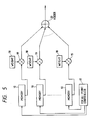
- Fig. 5 is a block diagram of a signal processing part of the ultrasonic diagnostic system according to the second embodiment of this invention.
- Fig. 6 is a diagram showing the relation between a propagation path distribution and a weighting function.
- Fig. 7 is a sectional view of the ultrasonic probe in the ultrasonic diagnostic system according to the second embodiment of this invention.
- Fig. 8 is a block diagram of a signal changing part and a signal processing part of the ultrasonic diagnostic system according to the second embodiment of this invention.
- Fig. 9 is a block diagram of a signal processing part of the ultrasonic diagnostic system according to the second embodiment of this invention.
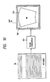
- Fig. 10 is a block diagram of a signal processing part and an image displaying part of the ultrasonic diagnostic system according to the second embodiment of this invention.
- Fig. 11 is a perspective view of an ultrasonic probe in an ultrasonic diagnostic system according to a third embodiment of this invention.
- Fig. 12 is a sectional view of the ultrasonic probe of Fig. 11.
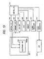
- Fig. 13 is a block diagram of the ultrasonic diagnostic system according to the third embodiment of this invention.
- Fig. 14 is a sectional diagram showing a catheter in the ultrasonic diagnostic system according to the third embodiment of this invention.
- Fig. 15 is a sectional view of an ultrasonic probe in an ultrasonic diagnostic system according to a fourth embodiment of this invention.
- With reference to Figs. 1 and 2, an ultrasonic diagnostic system includes an
ultrasonic probe 1 having acylindrical casing 2. Anarray 3 of ultrasonic-to-electrical transducer elements is disposed in a front end of thecasing 2. Thetransducer element array 3 is provided with an acoustic lens, a matching layer, and a backing layer in a known manner. Anelectronic circuit 4 associated with thetransducer element array 3 is accommodated in the region of thecasing 2 which extends adjacently rearward of thetransducer element array 3. A plurality of signal lines connected to theelectronic circuit 4 extend in theinterior 5 of thecasing 2 to conduct a transmission signal, a received signal, and a control signal to and from theelectronic circuit 4. - In the
transducer element array 3, the transducer elements are aligned along a line. In other words, thetransducer element array 3 has a linear arrangement. Thetransducer element array 3 has an active surface (a transmitting/receiving surface) via which ultrasonic waves are transmitted and received. The active surface of thetransducer element array 3 faces frontward with respect to thecasing 2. Theelectronic circuit 4 is of a known structure, having a channel-changing function and a transmission/reception (T/S) switching function. During the transmission and the reception of ultrasonic waves via thetransducer element array 3, theelectronic circuit 4 selects one or more of the transducer elements as active elements and sequentially changes the active elements in a known manner. Theelectronic circuit 4 is electrically connected to a main part of the ultrasonic diagnostic system via the signal lines. - As shown in Fig. 3, the main part of the ultrasonic diagnostic system includes a
control circuit 6, a transmission circuit 7, and areception circuit 8 connected to theelectronic circuit 4 within theultrasonic probe 1. Thecontrol circuit 6 serves to control theelectronic circuit 4 in response to a signal fed from acontroller 13. The transmission circuit 7 feeds a transmission signal to thetransducer element array 3 via theelectronic circuit 4 in response to a signal fed from thecontroller 13, and thetransducer element array 3 emits ultrasonic wave in response to the transmission signal. Echoes of ultrasonic wave are received by thetransducer element array 4 and are converted by thetransducer element array 4 into corresponding electric echo signals, which are transmitted to thereception circuit 8 via theelectronic circuit 4 and are amplified and processed by thereception circuit 8 in response to a signal fed from thecontroller 13. - The output signal from the
reception circuit 8 is converted by an A/D converter 9 into a corresponding digital signal, which is stored into amemory 10. Timings of operation of the A/D converter 9 and thememory 10 are controlled by signals fed from thecontroller 13. The digital signal is read out from thememory 10, and is then processed by a signal processor 11 into image data in response to a signal fed from thecontroller 13. The image data is converted by avideo generator 12 into a corresponding video signal in response to a signal fed from thecontroller 13. Thevideo generator 12 includes a digital scan converter. The video signal is fed from thevideo generator 12 to aCRT 14, and an image represented by the video signal is indicated by theCRT 14. The devices 6-12 are controlled by thecontroller 13. - The ultrasonic diagnostic system of Figs. 1-3 operates as follows. The
ultrasonic probe 1 is inserted into a tube, a blood vessel, or a coelom of an examined body. One or more of the transducer elements in thetransducer element array 3 are sequentially selected by theelectronic circuit 4 as active transducer elements in response to a control signal fed from thecontrol circuit 6. The selected transducer elements are fed with a transmission signal from the transmission circuit 7, emitting ultrasonic wave pulses toward a region of the body which extends in front of the end of theprobe casing 2. - Portions of the emitted ultrasonic wave pulses are reflected within the body, being returned to the
transducer element array 3 as echo pulses. The echo pulses received by the selected transducer elements (the active transducer elements) are converted into corresponding electric echo signals, which are transmitted to thereception circuit 8 via theelectronic circuit 4. - The transducer elements in the
transducer element array 3 compose a given number of different channels. During the transmission and the reception of the ultrasonic wave pulses, the selected transducer elements are changed to sequentially activate the channels to scan a given region of the body which extends in front of theprobe casing 2. - The electric echo signals are amplified and processed by the
reception circuit 8. The output signal from thereception circuit 8 is converted by the A/D converter 9 into a corresponding digital signal, which is stored into thememory 10. The previously-mentioned process is reiterated and thus the digital signal is accumulated in thememory 10 until the digital signal in thememory 10 corresponds to a desired complete image of the body. - The signal processor 11 reads out the digital signal from the
memory 10, subjecting the digital signal to a delaying process, a weighting process, and an adding process in accordance with an aperture synthesis technique and thereby converting the digital signal into image data. The image data is converted by thevideo generator 12 into a corresponding video signal. The video signal is fed from thevideo generator 12 to theCRT 14, and the image represented by the video signal is indicated by theCRT 14. The indicated image agrees with a sectional image of the region of the body which extends in front of the end of theprobe casing 2. A sequence of the previously-mentioned operations is controlled by thecontroller 13. For this purpose, thecontroller 13 includes a time base. - The outside diameter of the
ultrasonic probe 1 is preferably set to a small value, for example, 2 mm or less so that theultrasonic probe 1 can be used within a small tube or coelom of the body. Since theultrasonic probe 1 scans the region of the body which extends in front of the end of theprobe casing 2, a block of the tube or coelom of the body can be accurately observed. - Since the
electronic circuit 4 is located adjacently rearward of thetransducer element array 3, signal lines connected between theelectronic circuit 4 and thetransducer element array 3 are prevented from extending through a great part of theinterior 5 of theprobe casing 2. This is advantageous for the miniaturization of theultrasonic probe 1. When theelectronic circuit 4 is composed of an IC chip, theultrasonic probe 1 can be further miniaturized. - The frequency of the used ultrasonic wave is preferably set to a value within a range of 20 MHz to 40 MHz in consideration of the damping of the ultrasonic wave, the resolution of the obtained image, and the sizes of the
ultrasonic probe 1 and the examined coelom and tube of the body. The transducer elements are preferably made of high-molecule piezoelectric material such as PVDF. - Figs. 4-10 relate to an ultrasonic diagnostic system according to a second embodiment of this invention which is similar to the embodiment of Figs. 1-3 except for design changes indicated hereinafter.
- In Fig. 4, the
reference character 3a denotes transducer elements composing atransducer element array 3 disposed in a front end of acasing 2 of anultrasonic probe 1. Anelectronic circuit 4 associated with thetransducer element array 3 includes an analog multiplexer which enables a decrease in the number of required signal lines. Theanalog multiplexer 4 has a function of changing connections corresponding to respective channels. For the simplicity of transmission and reception control, theanalog multiplexer 4 is designed so that ultrasonic wave will be transmitted and echo ultrasonic wave will be received by asame transducer element 3a which constitutes an active element. One of thetransducer elements 3a in thetransducer element array 3 is sequentially selected by themultiplexer 4 as an active element for scanning a givensector region 16 of an examined body which extends in front of the end of theprobe casing 2. - Each
transducer element 3a has abroad directivity 15 close to a non-directional characteristic. During a single transmission and reception process, anactive transducer element 3a receives echo ultrasonic waves from a wide region of an examined body which extends in front of the end of theprobe casing 2. The received echo ultrasonic waves are converted by theactive transducer element 3a into a corresponding electric signal. The electric signal is fed to a main part of the ultrasonic diagnostic system via theanalog multiplexer 4 and signal lines, being processed and converted into a corresponding digital signal as in the embodiment of Figs. 1-3. The digital signal is stored into amemory 10 of Fig. 5. Specifically, time segments of the digital signal are sequentially stored into storage locations (storage segments) of thememory 10. It should be noted that the connection of thememory 10 to theanalog multiplexer 4 is omitted from Fig. 5. - In Fig. 5, a focal-
point controller 17 serves to control a segment of thememory 10 from which data is read out. Specifically, the focal-point controller 17 includes an address controller operating on thememory 10. Data read out from the segments of thememory 10 are fed tomultipliers 19 respectively. Themultiplier 19 multiplies the fed data byweights 18 respectively. The output data from themultipliers 19 which represent the results of the multiplications are added by anadder 20. - Since time segments of the echo digital signal correspond to different object points to be imaged and since the time segments of the echo digital signal are sequentially stored into storage locations (storage segments) of the
memory 10, the addresses of the storage locations of thememory 10 have a fixed relation with the object points to be imaged. For each object point to be imaged, the focal-point controller 17 calculates a related address on the basis of the distance between the usedtransducer element 3a and the object point, and the focal-point controller 17 feeds the calculated address to thememory 10 so that data is read out from the segment of thememory 10 which is designated by the calculated address. The address fed to thememory 10 is periodically updated so that data will be sequentially read out from the segments of thememory 10. The data read out from the segments of thememory 10 are fed to themultipliers 19 respectively. Thus, themultipliers 19 correspond to the respective object points. Theweights 18 fed to themultipliers 19 are preset so as to depend on the distances between the usedtransducer element 3a and the corresponding object points. Themultipliers 19 multiply the data by theweights 18. The output data from themultipliers 19 are combined by theadder 20 into image data which sequentially represents images of the object points. The previously-mentioned signal processing is executed for each of object points within the sector scannedregion 16 of the body, so that image data corresponding to an image of the scannedregion 16 can be obtained finally. - In Fig. 6, the numeral 21 denotes a distribution of propagation paths between the
transducer elements 3a and the object points which occur in the case where thetransducer elements 3a are continuously arranged. As shown in Fig. 6, aweighting function 22 which determines theweights 18 is set into agreement with thepropagation path distribution 21. This design enables the suppression of components of the image data which are caused by a grating lobe of thetransducer element array 3. It should be noted that the grating lobe results from an equally-spacing arrangement of thetransducer elements 3a. - In the case of a linear arrangement of the
transducer elements 3a, a propagation path distribution P(r) can be statistically expressed by the following equations.


where the character R denotes the distance between a transducer element and an object point; the characters Rmin and Rmax denote predetermined limits; and the character Y denotes the distance between the line of the transducer elements and the object point. A forward and backward propagation path distribution Ptr(r) is given as a convolution of the equations (1), and is expressed by the following equation.

The weighting function determining theweights 18 is chosen on the basis of the equations (1) and (2). - It should be noted that a propagation path distribution can be calculated for a convex configuration of transducer elements, and that a used propagation path distribution is required to depend on a configuration of transducer elements.
- As shown in Fig. 7, the sector scanned
region 16 is truncated, and an imaginary vertex is defined as areference point 72 with respect to the sector scannedregion 16. Scanninglines 71 compose the sector scannedregion 16. Extensions of thescanning lines 71 pass through thereference point 72. It is now assumed that areflection point 73 at which ultrasonic waves emitted from thetransducer elements 3a are reflected is present within the sector scannedregion 16 as shown in Fig. 7. There arepropagation paths 74 via which forward and backward ultrasonic waves travel between thetransducer elements 3a and thereflection point 73. Thereference point 72 is chosen to lie rearward of thetransducer element array 3 so that a dead angle of theultrasonic probe 1 can be decreased and a visual field of theultrasonic probe 1 can be widened. - A further description will be given hereinafter with reference to Fig. 8. As described previously, a transmission and reception process is executed for each of the
transducer elements 3a by the operation of theanalog multiplexer 4. An electric echo signal corresponding to onetransducer element 3a is transmitted from thetraducer element 3a to areception circuit 8 via theanalog multiplexer 4, being amplified by thereception circuit 8 and then being converted by an A/D converter 9 into a corresponding digital echo signal. Thememory 10 includes line segments which correspond to thetransducer elements 3a respectively. The digital echo signal corresponding to onetransducer element 3a is stored into the corresponding line segment of thememory 10. Since theanalog multiplexer 4 sequentially selects one of thetransducer elements 3a, the digital signals corresponding to thetransducer elements 3a are stored into the corresponding line segments of thememory 10 respectively. - A consideration will be given of three points A, B, and C which lie within the sector scanned
region 16 as shown in Fig. 8. It is now assumed that the point A agrees with a reflection point. In this case, the digital signals stored in the line segments of thememory 10 representrespective waveforms 81 such as shown in Fig. 8. A signal representing conditions of the point A is synthesized on the basis of data read out from storage locations of the line segments of thememory 10 which are arranged along acurved line 82. A signal representing conditions of the point B is synthesized on the basis of data read out from storage locations of the line segments of thememory 10 which are arranged along acurved line 83. A signal representing conditions of the point C is synthesized on the basis of data read out from storage locations of the line segments of thememory 10 which are arranged along acurved line 84. Reading data from storage locations of the line segments of thememory 10 is executed in a sequence determined by ascanning line 71 of Fig. 7. - As shown in Fig. 9, the
weights 18 are fed to themultipliers 19 respectively. Theweights 18 are outputted from a ROM 91 which previously stores a map containing data of theweights 18. Themultipliers 19 are fed with the data from the line segments of thememory 10 respectively, and multiply the data by theweights 19 respectively. As described previously, theweights 18 are designed in correspondence with thetransducer elements 3a so as to suppress components of resultant image data which are caused by a grating lobe of thetransducer element array 3. Further, theweights 18 are predetermined in correspondence with respective object points. The output data from themultipliers 19 are combined by theadder 20 into a time segment of aresultant signal 93 which corresponds to one object point on ascanning line 71. The weighting process by themultipliers 19 and the adding process by theadder 20 are periodically reiterated for all object points on ascanning line 71, so that theresultant signal 93 corresponding to acomplete scanning line 71 is obtained finally. Aprocessor 94 subjects theresultant signal 93 to compression and detection so that a desired dynamic range of a reproduced image can be satisfied. The compression and detection by theprocessor 94 converts theresultant signal 93 intocorresponding image data 96, which is written into amemory 95. Thememory 95 has line segments which correspond to scanninglines 71 respectively. Theimage data 96 is stored into the corresponding line segment of thememory 95. This process is reiterated for all scanninglines 71 so thatimage data 96 corresponding to one frame is stored in thememory 95. In Fig. 9, the data in the respective line segments of thememory 95 represent waveforms which occur in the case where the point A of Fig. 8 agrees with a reflection point. - With reference to Fig. 10, the image data are sequentially read out from the
memory 95 by adigital scan converter 101, being converted by thescan converter 101 into a video signal. The video signal is fed to aCRT 14 so that animage 103 represented by the video signal is indicated on asector region 102 of theCRT 14. Theindicated image 103 agrees with an image of the sector scannedregion 16 of the body. Theindicated image 103 has a sector shape similar to the sector shape of the scannedregion 16. - This embodiment features that the adverse effect of a grating lobe of the
transducer element array 3 is suppressed by a weighting process considering a propagation path distribution. - With reference to Figs. 11 and 12, an ultrasonic diagnostic system includes an
ultrasonic probe 301 provided on a front end of a catheter. Theultrasonic probe 301 has an ultrasonic wave transmitting/receivingsection 302. The ultrasonic wave transmitting/receivingsection 302 includes anarray 303 of ultrasonic-to-electrical transducer elements, and anelectronic circuit 304 associated with thetransducer element array 303. - The
transducer element array 303 has an ultrasonic wave transmitting/receiving surface which faces frontward with respect to the end of the catheter. Thetransducer element array 303 has a convex shape. Theelectronic circuit 304 is disposed in the region of the interior of the catheter which extends adjacently rearward of thetransducer element array 303. Theelectronic circuit 304 is of a known structure, having a channel-changing function and a transmission/reception (T/S) switching function. During the transmission and the reception of ultrasonic wave via thetransducer element array 303, theelectronic circuit 304 selects one or more of the transducer elements as active elements and sequentially changes the active elements in a known manner. Theelectronic circuit 304 is electrically connected to a main part of the ultrasonic diagnostic system via signal lines. The signal lines extend in the interior of the catheter to conduct a transmission signal, a received signal, and a control signal to and from theelectronic circuit 304. - As shown in Fig. 13, the main part of the ultrasonic diagnostic system includes a
control circuit 305, atransmission circuit 306, and areception circuit 307 connected to theelectronic circuit 304 within theultrasonic probe 301. Thecontrol circuit 305 serves to control theelectronic circuit 304 in response to a signal fed from acontroller 312. Thetransmission circuit 306 feeds a transmission signal to thetransducer element array 303 via theelectronic circuit 304 in response to a signal fed from thecontroller 312, and thetransducer element array 303 emits ultrasonic wave in response to the transmission signal. Echoes of ultrasonic wave are received by thetransducer element array 304 and are converted by thetransducer element array 304 into corresponding electric signals, which are transmitted to thereception circuit 307 via theelectronic circuit 304 and are amplified and processed by thereception circuit 307 in response to a signal fed from thecontroller 312. - The output signal from the
reception circuit 307 is converted by an A/D converter 308 to a corresponding digital signal, which is stored into amemory 309. Timings of operation of the A/D converter 308 and thememory 309 are controlled by signals fed from thecontroller 312. The digital signal is read out from thememory 309, and is then processed by asignal processor 310 into image data in response to a signal fed from thecontroller 312. The image data is converted by avideo generator 311 into a corresponding video signal in response to a signal fed from thecontroller 312. Thevideo generator 311 includes a digital scan converter. The video signal is fed from thevideo generator 311 to aCRT 313, and an image represented by the video signal is indicated by theCRT 313. The devices 305-311 are controlled by thecontroller 312. - The ultrasonic diagnostic system of Figs. 11-13 operates as follows. As shown in Fig. 14, the catheter provided with the
ultrasonic probe 301 is inserted into ablood vessel 314 of an examined body. One or more of the transducer elements in thetransducer element array 303 are sequentially selected by theelectronic circuit 304 as active transducer elements in response to a control signal fed from thecontrol circuit 305. The selected transducer elements are fed with a transmission signal from thetransmission circuit 306, emitting ultrasonic wave pulses toward a region of the body which extends in front of the end of the catheter. - Portions of the emitted ultrasonic wave pulses are reflected at blood vessel walls and other parts within the body, being returned to the
transducer element array 303 as echo pulses. The echo pulses received by the selected transducer elements (the active transducer elements) are converted into corresponding electric echo signals, which are transmitted to thereception circuit 307 via theelectronic circuit 304. - The transducer elements in the
transducer element array 303 compose a given number of different channels. During the transmission and the reception of the ultrasonic wave pulses, the selected transducer elements are changed to sequentially activate the channels to scan a givensector region 315 of the body which extends in front of the catheter. - The echo signals are amplified and processed by the
reception circuit 307. The output signal from thereception circuit 307 is converted by the A/D converter 308 into a corresponding digital signal, which is stored into thememory 309. The previously-mentioned process is reiterated and thus the digital signal is accumulated in thememory 309 until the digital signal in thememory 309 corresponds to a desired complete image of the body. - The
signal processor 310 reads out the digital signal from thememory 309, subjecting the digital signal to a delaying process, a weighting process, and an adding process in accordance with an aperture synthesis technique and thereby converting the digital signal into image data. The image data is converted by thevideo generator 311 into a corresponding video signal. The video signal is fed from thevideo generator 311 to theCRT 313, and the image represented by the video signal is indicated by theCRT 313. The indicated image agrees with an image of the sector scannedregion 315 of the body which extends in front of the end of the catheter. A sequence of the previously-mentioned operations is controlled by thecontroller 312. For this purpose, thecontroller 312 includes a time base. - The outside diameter of the ultrasonic probe 301 (the catheter) is preferably set to a small value, for example, 2 mm or less so that the
ultrasonic probe 301 can be used within a small tube or coelom of the body. Since theultrasonic probe 301 scans the region of the body which extends in front of the end of the catheter, a block of the tube or coelom of the body can be accurately observed. - Since the
electronic circuit 304 is located adjacently rearward of thetransducer element array 303, signal lines connected between theelectronic circuit 304 and thetransducer element array 303 are prevented from extending through a great part of the interior of the catheter. This is advantageous for the miniaturization of the catheter. When theelectronic circuit 304 is composed of an IC chip, theultrasonic probe 301 can be further miniaturized. - The frequency of the used ultrasonic wave is preferably set to a value within a range of 20 MHz to 40 MHz in consideration of the damping of the ultrasonic wave, the resolution of the obtained image, and the sizes of the
ultrasonic probe 301 and the examined coelom and tube of the body. The transducer elements are preferably made of high-molecule piezoelectric material such as PVDF. - Fig. 15 shows a fourth embodiment of this invention which is similar to the embodiment of Figs. 11-14 except for an additional design indicated hereinafter.
- As shown in Fig. 15, the fourth embodiment includes an
optical fiber 316 extending along the central axis of a catheter. Theoptical fiber 316 is connected to a laser within a main part of an ultrasonic diagnostic system. Theoptical fiber 316 conducts a beam of light emitted from the laser. Theoptical fiber 316 extends through atransducer element array 303 and reaches the front end face of the catheter. The front end face of the catheter has anoutput window aperture 317 connected to theoptical fiber 316. The laser light beam is emitted frontward from the end of the catheter via theoutput window aperture 317. The emitted laser light beam is used for treatment. - A wrong point in a tube or a blood vessel of an examined body can be treated by the application of the laser light beam while an image of a related part of the body is observed through ultrasonic imaging. To enable such a process, the
output window aperture 317 and thetransducer element array 303 are arranged so that the axis of the path of the emitted laser light beam will extend in the region scanned by the ultrasonic wave.
Claims (13)
- An ultrasonic diagnostic system comprising:
a probe having an elongated form with an end;
a transducer element array disposed in the probe for emitting ultrasonic wave frontward with respect to the end of the probe and receiving echo ultrasonic waves, the transducer element array converting the received echo ultrasonic waves into corresponding electric echo signals;
means for processing the electric echo signals according to a predetermined aperture synthesis technique, and for generating an image signal on the basis of the electric echo signals; and
means for reproducing an image of a region in front of the end of the probe in response to the image signal. - The ultrasonic diagnostic system of claim 1 wherein the processing means comprises means for suppressing components of the image signal which are caused by a grating lobe of the transducer element array.
- The ultrasonic diagnostic system of claim 1 wherein the grating-lobe suppressing means comprises means for weighting the electric echo signals.
- The ultrasonic diagnostic system of claim 1 wherein the imaged region has a sector shape.
- An ultrasonic diagnostic system comprising:
a catheter having an end; and
a transducer element array disposed in the end of the catheter for emitting ultrasonic wave frontward with respect to the end of the catheter and receiving echo ultrasonic waves to scan a region in front of the end of the catheter. - The ultrasonic diagnostic system of claim 5 further comprising an electronic circuit disposed in the catheter and extending adjacently rearward of the transducer element array for selecting one or more of transducer elements of the transducer element array as active elements and sequentially changing the active elements.
- The ultrasonic diagnostic system of claim 5 further comprising means for scanning the region in front of the end of the catheter according to a predetermined aperture synthesis technique.
- The ultrasonic diagnostic system of claim 5 wherein the scanned region has a sector shape.
- An ultrasonic diagnostic system comprising:
a catheter having an end;
a transducer element array disposed in the end of the catheter for emitting ultrasonic wave frontward with respect to the end of the catheter and receiving echo ultrasonic waves to scan a region in front of the end of the catheter; and
means for emitting a laser light beam frontward from the end of the catheter. - The ultrasonic diagnostic system of claim 9 further comprising an electronic circuit disposed in the catheter and extending adjacently rearward of the transducer element array for selecting one or more of transducer elements of the transducer element array as active elements and sequentially changing the active elements.
- The ultrasonic diagnostic system of claim 9 wherein the emitting means comprises an optical fiber extending in the catheter and reaching an outlet window aperture in the end of the catheter.
- The ultrasonic diagnostic system of claim 9 further comprising means for scanning the region in front of the end of the catheter according to a predetermined aperture synthesis technique.
- The ultrasonic diagnostic system of claim 9 wherein the scanned region has a sector shape.
Applications Claiming Priority (6)
| Application Number | Priority Date | Filing Date | Title |
|---|---|---|---|
| JP2076041A JPH03275047A (en) | 1990-03-26 | 1990-03-26 | Catheter type ultrasonic diagnostic apparatus |
| JP7604190 | 1990-03-26 | ||
| JP76041/90 | 1990-03-26 | ||
| JP328688/90 | 1990-11-27 | ||
| JP2328688A JPH04193270A (en) | 1990-11-27 | 1990-11-27 | Ultrasonic diagnosis apparatus |
| JP32868890 | 1990-11-27 |
Publications (3)
| Publication Number | Publication Date |
|---|---|
| EP0450431A2 true EP0450431A2 (en) | 1991-10-09 |
| EP0450431A3 EP0450431A3 (en) | 1993-02-24 |
| EP0450431B1 EP0450431B1 (en) | 1999-06-30 |
Family
ID=26417200
Family Applications (1)
| Application Number | Title | Priority Date | Filing Date |
|---|---|---|---|
| EP91104566A Expired - Lifetime EP0450431B1 (en) | 1990-03-26 | 1991-03-22 | Ultrasonic diagnostic system |
Country Status (3)
| Country | Link |
|---|---|
| US (1) | US5161537A (en) |
| EP (1) | EP0450431B1 (en) |
| DE (1) | DE69131388T2 (en) |
Cited By (1)
| Publication number | Priority date | Publication date | Assignee | Title |
|---|---|---|---|---|
| WO2006003606A2 (en) * | 2004-06-29 | 2006-01-12 | Koninklijke Philips Electronics, N.V. | System simplification for an ultrasound-based perfusion detection system |
Families Citing this family (24)
| Publication number | Priority date | Publication date | Assignee | Title |
|---|---|---|---|---|
| US5713363A (en) * | 1991-11-08 | 1998-02-03 | Mayo Foundation For Medical Education And Research | Ultrasound catheter and method for imaging and hemodynamic monitoring |
| US5704361A (en) * | 1991-11-08 | 1998-01-06 | Mayo Foundation For Medical Education And Research | Volumetric image ultrasound transducer underfluid catheter system |
| US5325860A (en) * | 1991-11-08 | 1994-07-05 | Mayo Foundation For Medical Education And Research | Ultrasonic and interventional catheter and method |
| US5373845A (en) * | 1992-05-22 | 1994-12-20 | Echo Cath, Ltd. | Apparatus and method for forward looking volume imaging |
| US5373849A (en) * | 1993-01-19 | 1994-12-20 | Cardiovascular Imaging Systems, Inc. | Forward viewing imaging catheter |
| US5453575A (en) * | 1993-02-01 | 1995-09-26 | Endosonics Corporation | Apparatus and method for detecting blood flow in intravascular ultrasonic imaging |
| AU1983397A (en) | 1996-02-29 | 1997-09-16 | Acuson Corporation | Multiple ultrasound image registration system, method and transducer |
| US5699805A (en) * | 1996-06-20 | 1997-12-23 | Mayo Foundation For Medical Education And Research | Longitudinal multiplane ultrasound transducer underfluid catheter system |
| US5876345A (en) * | 1997-02-27 | 1999-03-02 | Acuson Corporation | Ultrasonic catheter, system and method for two dimensional imaging or three-dimensional reconstruction |
| US6045508A (en) * | 1997-02-27 | 2000-04-04 | Acuson Corporation | Ultrasonic probe, system and method for two-dimensional imaging or three-dimensional reconstruction |
| US6171247B1 (en) | 1997-06-13 | 2001-01-09 | Mayo Foundation For Medical Education And Research | Underfluid catheter system and method having a rotatable multiplane transducer |
| US5957850A (en) * | 1997-09-29 | 1999-09-28 | Acuson Corporation | Multi-array pencil-sized ultrasound transducer and method of imaging and manufacture |
| US6059731A (en) * | 1998-08-19 | 2000-05-09 | Mayo Foundation For Medical Education And Research | Simultaneous side-and-end viewing underfluid catheter |
| US6398736B1 (en) | 1999-03-31 | 2002-06-04 | Mayo Foundation For Medical Education And Research | Parametric imaging ultrasound catheter |
| US20080236286A1 (en) * | 2007-03-29 | 2008-10-02 | Clive Chemo Lam | Non-destructive tubular testing |
| US20110284508A1 (en) * | 2010-05-21 | 2011-11-24 | Kabushiki Kaisha Toshiba | Welding system and welding method |
| US9217731B2 (en) | 2010-05-21 | 2015-12-22 | Kabushiki Kaisha Toshiba | Welding inspection method and apparatus thereof |
| KR20150068846A (en) * | 2013-12-12 | 2015-06-22 | 삼성전자주식회사 | Ultrasonic diagnostic apparatus and control method thereof |
| US20180160226A1 (en) * | 2016-12-05 | 2018-06-07 | Semiconductor Components Industries, Llc | Reducing or eliminating transducer reverberation |
| CN111347157B (en) * | 2018-12-21 | 2023-04-28 | 松下知识产权经营株式会社 | Laser welding device and laser welding method |
| JP7233316B2 (en) | 2019-06-21 | 2023-03-06 | 朝日インテック株式会社 | Guidewires, guidewire systems and imaging guidewires |
| US11442155B2 (en) | 2019-10-02 | 2022-09-13 | Semiconductor Components Industries, Llc | Devices, systems and processes for detecting saturation of received echo signals |
| US11759822B2 (en) | 2020-01-21 | 2023-09-19 | Semiconductor Components Industries, Llc | Devices, systems and processes for improving frequency measurements during reverberation periods for ultra-sonic transducers |
| US11520027B2 (en) | 2020-02-14 | 2022-12-06 | Semiconductor Components Industries, Llc | Devices, systems and processes for ultra-short range detection of obstacles |
Citations (7)
| Publication number | Priority date | Publication date | Assignee | Title |
|---|---|---|---|---|
| US4084582A (en) * | 1976-03-11 | 1978-04-18 | New York Institute Of Technology | Ultrasonic imaging system |
| US4145931A (en) * | 1978-01-03 | 1979-03-27 | Raytheon Company | Fresnel focussed imaging system |
| EP0123594A1 (en) * | 1983-04-06 | 1984-10-31 | Universite Francois Rabelais | Endoscopic probe for viewing and ultrasonic scanning echography |
| US4661814A (en) * | 1984-04-04 | 1987-04-28 | Siemens Aktiengesellschaft | Device for reading out a two-dimensional charge pattern by means of an array |
| US4793184A (en) * | 1985-10-09 | 1988-12-27 | Hitachi Ltd. | Ultrasonic imaging apparatus and method of forming an ultrasonic image of an object |
| GB2212267A (en) * | 1987-11-11 | 1989-07-19 | Circulation Res Ltd | Three dimensional ultrasonic imaging apparatus |
| EP0430450A2 (en) * | 1989-11-28 | 1991-06-05 | Hewlett-Packard Company | 2-D phased array ultrasound imaging system with distributed phasing |
Family Cites Families (6)
| Publication number | Priority date | Publication date | Assignee | Title |
|---|---|---|---|---|
| DE3783281T2 (en) * | 1986-07-07 | 1993-07-22 | Matsushita Electric Ind Co Ltd | ULTRASONIC PROBE. |
| US4991588A (en) * | 1986-07-21 | 1991-02-12 | Pfizer Hospital Products Group, Inc. | Doppler guide wire |
| JPS63181748A (en) * | 1987-01-22 | 1988-07-26 | 株式会社東芝 | Ultrasonic diagnostic apparatus |
| US5054491A (en) * | 1988-10-17 | 1991-10-08 | Olympus Optical Co., Ltd. | Ultrasonic endoscope apparatus |
| US5022399A (en) * | 1989-05-10 | 1991-06-11 | Biegeleisen Ken P | Venoscope |
| US5038789A (en) * | 1989-09-28 | 1991-08-13 | Frazin Leon J | Method and device for doppler-guided retrograde catheterization |
-
1991
- 1991-03-20 US US07/672,413 patent/US5161537A/en not_active Expired - Lifetime
- 1991-03-22 EP EP91104566A patent/EP0450431B1/en not_active Expired - Lifetime
- 1991-03-22 DE DE69131388T patent/DE69131388T2/en not_active Expired - Fee Related
Patent Citations (7)
| Publication number | Priority date | Publication date | Assignee | Title |
|---|---|---|---|---|
| US4084582A (en) * | 1976-03-11 | 1978-04-18 | New York Institute Of Technology | Ultrasonic imaging system |
| US4145931A (en) * | 1978-01-03 | 1979-03-27 | Raytheon Company | Fresnel focussed imaging system |
| EP0123594A1 (en) * | 1983-04-06 | 1984-10-31 | Universite Francois Rabelais | Endoscopic probe for viewing and ultrasonic scanning echography |
| US4661814A (en) * | 1984-04-04 | 1987-04-28 | Siemens Aktiengesellschaft | Device for reading out a two-dimensional charge pattern by means of an array |
| US4793184A (en) * | 1985-10-09 | 1988-12-27 | Hitachi Ltd. | Ultrasonic imaging apparatus and method of forming an ultrasonic image of an object |
| GB2212267A (en) * | 1987-11-11 | 1989-07-19 | Circulation Res Ltd | Three dimensional ultrasonic imaging apparatus |
| EP0430450A2 (en) * | 1989-11-28 | 1991-06-05 | Hewlett-Packard Company | 2-D phased array ultrasound imaging system with distributed phasing |
Cited By (2)
| Publication number | Priority date | Publication date | Assignee | Title |
|---|---|---|---|---|
| WO2006003606A2 (en) * | 2004-06-29 | 2006-01-12 | Koninklijke Philips Electronics, N.V. | System simplification for an ultrasound-based perfusion detection system |
| WO2006003606A3 (en) * | 2004-06-29 | 2006-05-11 | Koninkl Philips Electronics Nv | System simplification for an ultrasound-based perfusion detection system |
Also Published As
| Publication number | Publication date |
|---|---|
| US5161537A (en) | 1992-11-10 |
| DE69131388T2 (en) | 1999-12-16 |
| EP0450431A3 (en) | 1993-02-24 |
| EP0450431B1 (en) | 1999-06-30 |
| DE69131388D1 (en) | 1999-08-05 |
Similar Documents
| Publication | Publication Date | Title |
|---|---|---|
| US5161537A (en) | Ultrasonic diagnostic system | |
| JP5281727B2 (en) | Method and apparatus for improving sidelobe performance of sparse arrays using harmonic imaging | |
| US4084582A (en) | Ultrasonic imaging system | |
| US4180792A (en) | Transmit-receive transducer array and ultrasonic imaging system | |
| US7087020B2 (en) | Ultrasound image reconstruction with receive aperture control | |
| US4471785A (en) | Ultrasonic imaging system with correction for velocity inhomogeneity and multipath interference using an ultrasonic imaging array | |
| US4207901A (en) | Ultrasound reflector | |
| JP4242472B2 (en) | Ultrasonic transducer array and ultrasonic imaging system | |
| US5579770A (en) | Multiple transmit zone splicing | |
| EP0087318B1 (en) | Ultrasonic diagnostic apparatus | |
| EP0155280B1 (en) | Body imaging using vectorial addition of acoustic reflections to achieve effect of scanning beam continuously focused in range | |
| US4333474A (en) | Ultrasonic imaging system | |
| US6790182B2 (en) | Ultrasound system and ultrasound diagnostic apparatus for imaging scatterers in a medium | |
| US6910380B2 (en) | Ultrasonic transmitting and receiving apparatus | |
| US8197412B2 (en) | Ultrasonic diagnostic apparatus | |
| EP0642036A2 (en) | Ultrasonic diagnostic equipment | |
| US4257271A (en) | Selectable delay system | |
| EP1504289A2 (en) | Ultrasound transducer | |
| US7011632B2 (en) | Methods and apparatus for ultrasonic compound imaging | |
| US4442713A (en) | Frequency varied ultrasonic imaging array | |
| US5065763A (en) | Combined reflection and transmssion untrasonic imaging method and apparatus | |
| EP1815795A1 (en) | Ultrasonographic device | |
| Ylitalo | On the signal-to-noise ratio of a synthetic aperture ultrasound imaging method | |
| JPH08289891A (en) | Ultrasonic diagnostic device | |
| JPS6331220B2 (en) |
Legal Events
| Date | Code | Title | Description |
|---|---|---|---|
| PUAI | Public reference made under article 153(3) epc to a published international application that has entered the european phase |
Free format text: ORIGINAL CODE: 0009012 |
|
| 17P | Request for examination filed |
Effective date: 19910322 |
|
| AK | Designated contracting states |
Kind code of ref document: A2 Designated state(s): DE FR GB |
|
| PUAL | Search report despatched |
Free format text: ORIGINAL CODE: 0009013 |
|
| AK | Designated contracting states |
Kind code of ref document: A3 Designated state(s): DE FR GB |
|
| 17Q | First examination report despatched |
Effective date: 19941117 |
|
| GRAG | Despatch of communication of intention to grant |
Free format text: ORIGINAL CODE: EPIDOS AGRA |
|
| GRAG | Despatch of communication of intention to grant |
Free format text: ORIGINAL CODE: EPIDOS AGRA |
|
| GRAH | Despatch of communication of intention to grant a patent |
Free format text: ORIGINAL CODE: EPIDOS IGRA |
|
| GRAH | Despatch of communication of intention to grant a patent |
Free format text: ORIGINAL CODE: EPIDOS IGRA |
|
| GRAA | (expected) grant |
Free format text: ORIGINAL CODE: 0009210 |
|
| AK | Designated contracting states |
Kind code of ref document: B1 Designated state(s): DE FR GB |
|
| REF | Corresponds to: |
Ref document number: 69131388 Country of ref document: DE Date of ref document: 19990805 |
|
| ET | Fr: translation filed | ||
| PLBE | No opposition filed within time limit |
Free format text: ORIGINAL CODE: 0009261 |
|
| STAA | Information on the status of an ep patent application or granted ep patent |
Free format text: STATUS: NO OPPOSITION FILED WITHIN TIME LIMIT |
|
| 26N | No opposition filed | ||
| REG | Reference to a national code |
Ref country code: GB Ref legal event code: IF02 |
|
| PGFP | Annual fee paid to national office [announced via postgrant information from national office to epo] |
Ref country code: FR Payment date: 20060308 Year of fee payment: 16 |
|
| PGFP | Annual fee paid to national office [announced via postgrant information from national office to epo] |
Ref country code: DE Payment date: 20060316 Year of fee payment: 16 |
|
| PGFP | Annual fee paid to national office [announced via postgrant information from national office to epo] |
Ref country code: GB Payment date: 20060322 Year of fee payment: 16 |
|
| GBPC | Gb: european patent ceased through non-payment of renewal fee |
Effective date: 20070322 |
|
| REG | Reference to a national code |
Ref country code: FR Ref legal event code: ST Effective date: 20071130 |
|
| PG25 | Lapsed in a contracting state [announced via postgrant information from national office to epo] |
Ref country code: DE Free format text: LAPSE BECAUSE OF NON-PAYMENT OF DUE FEES Effective date: 20071002 |
|
| PG25 | Lapsed in a contracting state [announced via postgrant information from national office to epo] |
Ref country code: GB Free format text: LAPSE BECAUSE OF NON-PAYMENT OF DUE FEES Effective date: 20070322 |
|
| PG25 | Lapsed in a contracting state [announced via postgrant information from national office to epo] |
Ref country code: FR Free format text: LAPSE BECAUSE OF NON-PAYMENT OF DUE FEES Effective date: 20070402 |