EP0451520A2 - Method of determining the progress and the amount produced in open-pit mine using satellite geodesy - Google Patents
Method of determining the progress and the amount produced in open-pit mine using satellite geodesy Download PDFInfo
- Publication number
- EP0451520A2 EP0451520A2 EP91103800A EP91103800A EP0451520A2 EP 0451520 A2 EP0451520 A2 EP 0451520A2 EP 91103800 A EP91103800 A EP 91103800A EP 91103800 A EP91103800 A EP 91103800A EP 0451520 A2 EP0451520 A2 EP 0451520A2
- Authority
- EP
- European Patent Office
- Prior art keywords
- receiver
- extraction device
- determined
- deposit
- satellites
- Prior art date
- Legal status (The legal status is an assumption and is not a legal conclusion. Google has not performed a legal analysis and makes no representation as to the accuracy of the status listed.)
- Granted
Links
Images

Classifications
-
- G—PHYSICS
- G01—MEASURING; TESTING
- G01S—RADIO DIRECTION-FINDING; RADIO NAVIGATION; DETERMINING DISTANCE OR VELOCITY BY USE OF RADIO WAVES; LOCATING OR PRESENCE-DETECTING BY USE OF THE REFLECTION OR RERADIATION OF RADIO WAVES; ANALOGOUS ARRANGEMENTS USING OTHER WAVES
- G01S19/00—Satellite radio beacon positioning systems; Determining position, velocity or attitude using signals transmitted by such systems
- G01S19/38—Determining a navigation solution using signals transmitted by a satellite radio beacon positioning system
- G01S19/39—Determining a navigation solution using signals transmitted by a satellite radio beacon positioning system the satellite radio beacon positioning system transmitting time-stamped messages, e.g. GPS [Global Positioning System], GLONASS [Global Orbiting Navigation Satellite System] or GALILEO
- G01S19/42—Determining position
- G01S19/51—Relative positioning
-
- E—FIXED CONSTRUCTIONS
- E02—HYDRAULIC ENGINEERING; FOUNDATIONS; SOIL SHIFTING
- E02F—DREDGING; SOIL-SHIFTING
- E02F3/00—Dredgers; Soil-shifting machines
- E02F3/04—Dredgers; Soil-shifting machines mechanically-driven
- E02F3/18—Dredgers; Soil-shifting machines mechanically-driven with digging wheels turning round an axis, e.g. bucket-type wheels
- E02F3/22—Component parts
- E02F3/26—Safety or control devices
-
- E—FIXED CONSTRUCTIONS
- E02—HYDRAULIC ENGINEERING; FOUNDATIONS; SOIL SHIFTING
- E02F—DREDGING; SOIL-SHIFTING
- E02F9/00—Component parts of dredgers or soil-shifting machines, not restricted to one of the kinds covered by groups E02F3/00 - E02F7/00
- E02F9/20—Drives; Control devices
- E02F9/2025—Particular purposes of control systems not otherwise provided for
-
- G—PHYSICS
- G01—MEASURING; TESTING
- G01S—RADIO DIRECTION-FINDING; RADIO NAVIGATION; DETERMINING DISTANCE OR VELOCITY BY USE OF RADIO WAVES; LOCATING OR PRESENCE-DETECTING BY USE OF THE REFLECTION OR RERADIATION OF RADIO WAVES; ANALOGOUS ARRANGEMENTS USING OTHER WAVES
- G01S19/00—Satellite radio beacon positioning systems; Determining position, velocity or attitude using signals transmitted by such systems
- G01S19/01—Satellite radio beacon positioning systems transmitting time-stamped messages, e.g. GPS [Global Positioning System], GLONASS [Global Orbiting Navigation Satellite System] or GALILEO
- G01S19/03—Cooperating elements; Interaction or communication between different cooperating elements or between cooperating elements and receivers
- G01S19/09—Cooperating elements; Interaction or communication between different cooperating elements or between cooperating elements and receivers providing processing capability normally carried out by the receiver
-
- G—PHYSICS
- G01—MEASURING; TESTING
- G01S—RADIO DIRECTION-FINDING; RADIO NAVIGATION; DETERMINING DISTANCE OR VELOCITY BY USE OF RADIO WAVES; LOCATING OR PRESENCE-DETECTING BY USE OF THE REFLECTION OR RERADIATION OF RADIO WAVES; ANALOGOUS ARRANGEMENTS USING OTHER WAVES
- G01S19/00—Satellite radio beacon positioning systems; Determining position, velocity or attitude using signals transmitted by such systems
- G01S19/01—Satellite radio beacon positioning systems transmitting time-stamped messages, e.g. GPS [Global Positioning System], GLONASS [Global Orbiting Navigation Satellite System] or GALILEO
- G01S19/13—Receivers
- G01S19/14—Receivers specially adapted for specific applications
-
- G—PHYSICS
- G01—MEASURING; TESTING
- G01S—RADIO DIRECTION-FINDING; RADIO NAVIGATION; DETERMINING DISTANCE OR VELOCITY BY USE OF RADIO WAVES; LOCATING OR PRESENCE-DETECTING BY USE OF THE REFLECTION OR RERADIATION OF RADIO WAVES; ANALOGOUS ARRANGEMENTS USING OTHER WAVES
- G01S19/00—Satellite radio beacon positioning systems; Determining position, velocity or attitude using signals transmitted by such systems
- G01S19/38—Determining a navigation solution using signals transmitted by a satellite radio beacon positioning system
- G01S19/39—Determining a navigation solution using signals transmitted by a satellite radio beacon positioning system the satellite radio beacon positioning system transmitting time-stamped messages, e.g. GPS [Global Positioning System], GLONASS [Global Orbiting Navigation Satellite System] or GALILEO
- G01S19/53—Determining attitude
Definitions
- the invention relates to a method for determining the progress of mining and the mined masses in a deposit in an open-cast mine, in which, when the masses are mined in the deposit, the geodetic position of a section of a large-scale extraction device is determined, which has a portable supporting structure on which the Section is movably attached, which carries at least one extraction device, wherein to determine this geodetic position, the measurement signals from at least four satellites are received by a first receiver, which is attached to the movable section.
- the geodetic position ie the latitude, longitude and elevation coordinates of a point using satellite geodesy
- at least four satellites are generally required, the emitted signals of which can be received simultaneously by a receiver that corresponds to the point to be determined.
- the coordinates of the point to be determined are determined in such a way that the distance from this point to three satellites is determined, the transit time, ie the time difference between arrival and transmission time, of the transmission signals being used to determine the distance.
- the fourth satellite is necessary to adjust the time systems and thus to determine the reference time. This ensures that the actual transit times of the signals can be determined. Since the respective coordinates of the satellites are known, they can be viewed from the respective distances and the time adjustment to the receiver whose coordinates are clearly determined.
- GPS Global Positioning System
- the Global Positioning System in the USA, which is currently under construction, is suitable for satellite geodesy.
- at least 21 navigation satellites are planned, which are arranged around the earth in such a way that at least four satellites can be targeted simultaneously from any point on the earth.
- an absolute position measurement ie. that is, if the coordinates of a point are determined directly from the measured distances, currently an accuracy of ⁇ 10 m.
- This deviation is particularly due to the fact that the transmission signals from the satellites in the form of electromagnetic waves have to pass through different media on their way to earth, which deflect the waves differently by refraction and influence their transit time differently. It is therefore expedient to provide a further receiver which is arranged in the vicinity of the point to be determined and whose coordinates are known.
- the so-called differential measurement method can then be used to eliminate the unforeseeable and unpredictable influences of the different media on the wave propagation, since it can be assumed that the signals to the respective receivers pass through roughly the same paths. With this measuring method, an accuracy of approx. ⁇ 0.01 m can currently be achieved.
- the time intervals between two coordinate determinations using satellite geodesy depend, among other things, on the computing speed of the computer which evaluates the received signals. Depending on the computing power, the measuring intervals can be, for example, only one second. This short investigation time The coordinates enable an almost continuous detection of the positions of moving devices.
- the possibility of the relatively precise determination of coordinates at short measuring intervals by means of satellite geodesy is intended to be made available for determining the coordinates of the extraction device of a portable large-scale extraction device.
- This is particularly the position of the bucket wheel of a bucket wheel excavator used in an open pit mine.
- the paddle wheel representing the extraction device is carried by a cantilever which corresponds to the section of the extraction device mentioned in the introduction.
- This boom is generally pivotally mounted in a vertical plane on the portable support structure of the bucket wheel excavator. In the following it is mainly spoken of a bucket-wheel excavator, without, however, being connected with any restriction.
- the balance of the masses gained and the current topography of the mine are of particular importance for the operation of an open-cast mine.
- a model of the deposit to be mined is generally created, which specifies the arrangement of the individual layers of the deposit, their thickness, etc. These layers are firstly those which contain the usable material, for example coal, lignite or the like, and secondly the layers which cover the layers of the usable material or are also temporarily stored and must be cleared away in order to include the layers to be able to dismantle usable material.
- a comparison between the initial situation and the current topography can be used to determine which quantities of which materials have already been cleared and where. This means that the current topography of the opencast mine is always reproduced by such a comparison.
- To determine the cleared masses according to the amount, location and nature are manual Surveying methods are customary, so that due to the associated relatively high expenditure of time, for example, a precise plan can only be drawn up once a week and the deposit model can be updated.
- the invention has for its object to improve the method of the type described above so that the determination of the position of the extraction device, for. B. a paddle wheel, a portable large extraction device with sufficient accuracy under all conditions occurring in practical operation is possible.
- the position of the section of the extraction device which is in engagement with the deposit should be able to be determined so precisely that a realistic balance of the masses which have already been obtained and a correspondingly more precise current open-cast mining plan can be drawn up.
- the arrangement of the further receiver on the vertically upward pointing pylon or a comparable component of the supporting structure of the large extraction device is therefore particularly expedient. This point is almost free of all interferences caused by the Large extraction device could be effected and thus has excellent reception possibilities.
- the boom is pivotally mounted vertically with respect to the supporting structure and thus also the pylon.
- the direction in which the extraction device, e.g. B. the paddle wheel is clearly from the - possibly changing - distance between the receivers, which corresponds to a defined angular position of the boom. As already mentioned, the distance can be determined from the determined coordinates.
- the transformation of the position coordinates into a local coordinate system has the advantage that the position and orientation of the extraction device are specified in the coordinate system of the open-cast mine, which simplifies control of the movements and use of the large extraction device.
- the positions of the receivers can be determined at intervals of 0.3 sec - 600 sec. It has proven to be particularly expedient to determine the positions of the receivers at intervals of 1 sec. In any case, in the quasi-continuous determination of the position, the distance covered by the extraction device during the extraction is also recorded.
- the further receiver is also arranged on the section of the large-scale extraction device carrying the extraction device or on its portable support structure which carries the movable section
- the location and orientation of the extraction device, apart from the negligible lateral inclination of the large extraction device, can be clearly determined, the position of the engaging section of the extraction device being determined by simple geometric relationships which depend on the design of the respective large extraction device.
- the bucket wheel excavator 6 shown in FIG. 2 of the drawing has a support structure 65 which is provided with a chassis 49.
- the support structure 65 can be pivoted about a vertical axis 50 with respect to the substructure with the chassis.
- a boom 43 is pivotally mounted in the vertical plane, which carries a paddle wheel 7 at its free end.
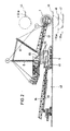
- the bucket wheel excavator is in use in an open-cast mine 4 on the surface of the earth, which is limited by the horizon 5 (FIG. 1).
- a first receiver 1 is arranged on the boom 43.
- a further receiver 2 is located on the pylon 8 of the supporting structure 65.
- a third receiver 3 is located in a fixed position in a building 9 which is arranged outside the open-cast mine 4 (FIG. 1).
- the earth is orbited by four satellites 10, 11, 12 and 13.
- the satellites move in orbits, which can be different from each other.
- the satellite 10 moves in orbit 14, satellite 11 in orbit 15, satellite 12 in orbit 16 and satellite 13 in orbit 17 around the earth.
- the orbits and coordinates of the satellites are known at all times and are transmitted with the signals coming from the satellites.
- the receivers 1, 2 and 3 are above the measuring beams 18, 19, 20, 21 and 22, 23, 24, 25 and 26, 27, 28, 29 with each of the Satellites 10, 11, 12, 13 in connection.
- FIG. 1 shows a temporal section from the transceiver situation between the receivers 1-3 and the satellites 10-13. It is guaranteed in any case that a receiver is connected to four satellites at any one time, so that the coordinates of the recipient can be clearly determined at any time.
- the bucket wheel excavator 6 can be moved horizontally on the formation 48.
- the bucket wheel excavator has a further boom 64 connected to the supporting structure 65. Both booms 43 and 64 are provided with conveyor belts, via which the masses obtained from the paddle wheel 7 reach a downstream conveyor belt 66.
- the further receiver arranged on the pylon 8 is not overshadowed by any structures of the bucket wheel excavator, so that the further receiver 2 can always be connected to the four satellites 10-13.
- the coordinates of the receivers 1 and 2 are determined simultaneously by means of satellite geodesy.
- the coordinates determine the distance between receivers 1 and 2.
- An angular position of the arm 43 in a vertical plane can be clearly assigned to this distance, as a result of which the position of the paddle wheel 7 with respect to the receivers 1 and 2 is also clearly defined. Since the receivers 1, 2 do not move relative to each other with respect to the axis of rotation 50, the direction of the straight line 67 which runs through the two receivers 1, 2 also means the alignment of the boom 43 and thus the position of the paddle wheel (7) in the Space set. The negligible lateral inclination of the bucket wheel excavator 6 can be disregarded.
- a further receiver must be provided on the device with which the inclination is detected.
- Fig. 2 shows that the engaged part of the circumference of the bucket wheel 7 depends on the angular position of the boom 43 in the vertical plane and the course of the surface of the deposit to be mined, on which the bucket wheel engages.
- the angular position of the straight line 67 running through the receivers 1, 2 differs depending on the position of the arc section in engagement on the circumference of the paddle wheel 7. It is possible, when determining the position of the impeller 7, the arc section which is in engagement determine the paddle wheel 7 and so geodetically determine the area of the deposit that is being cleared. It is the area with which the paddle wheel is engaged.
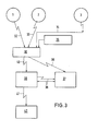
- the receivers 1 and 2 which are arranged on the bucket wheel excavator 6, feed their measurement data into a process computer 30 via the connections 32, 33. This can be arranged on the bucket wheel excavator 6, for example, within its early stage.
- the connections 32-34 can, for example, be lines or radio links for data transmission.
- the process computer 30 is also assigned a control unit 35, by means of which data relating to the type of material obtained from the bucket wheel excavator 6 and signals for a stop or start of the bucket wheel 7 and signals for the curved section of the bucket wheel can be transmitted.
- Both the process computer 30 and the main computer 38 continuously connected to it via the line 40 can contain information or data relating to a digital model of the deposit that is being processed by the bucket wheel excavator 6. It is common to provide a computer 37 for operational monitoring, which collects and maintains statistical data from the opencast mining operation. Such data consist, for example, of information about the operation or malfunctions of belt systems or the occupancy of belt scales, etc.
- the connection 36 between the process computer 30 and the computer 37 is established, for example, via a radio link 39 or a data cable.
- the computer 37 for operational monitoring is also connected to the main computer 38, which is installed, for example, in the marquetry. Corrections are exchanged between the computers 37 and 38 via the mutual connections 39.
- the main computer 38 installed in the marquetry is also on call via the connection 40 with the process computer 30 on the bucket wheel excavator 6. This creates a link between the three computers 30, 37 and 38, which enables these three computers to communicate with one another.
- the main computer 38 is still connected via a connection 41 to a mainframe 42, which can be set up at another location. In the mainframe computer, all data relating to the operations that go beyond the dismantling are stored. The data can be transmitted via the connections 36, 39, 40 and 41 shown both by radio and by cable, for example copper or glass fiber cable.
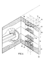
- FIG. 4 Details of the dismantling are shown schematically in FIG. 4.
- the bucket wheel 7 is moved so that it successively dredges the areas that are designated as excavator disks 51, 52, 53 within the deposit model shown in FIG. 4.
- the excavator disks 51 - 53 are arranged vertically one above the other and each correspond to the thickness of a layer which can be excavated by the bucket wheel 7 in the course of a single cut with the height position maintained at a constant level by pivoting the bucket wheel excavator 6 about the vertical axis 50.
- the open-cast mine and thus the excavator disks 51-53 are subdivided into a grid of square, vertically running columns 54, the cross-sectional areas of which form a grid with the edge lengths 55, 56, which each have a length of 4 m, for example.
- the columns extend across the entire depth of the open pit, or at least all three Excavator discs 51-53.
- each of the columns 54 is assigned a specific number or address, which is stored in at least one of the computers 30 or 38 and corresponds to the position of the columns.
- the procedure is such that wherever the impeller 7 or the engaged circumference of the impeller 7 is determined within the deposit model, the mass still present from the column 54 above the position of the impeller 7 is calculated Deposit model is removed. Depending on whether it is coal, overburden or loess, the cleared materials are assigned to specific computer memories, whereby a current mass balance can be created. The amount of overburden and coal remaining in the deposit model and the materials actually mined can be precisely determined in this way.
- the current open-pit geometry can be continuously derived from the deposit model from the respectively determined upper boundaries of the columns 54 and possibly displayed on a screen arranged in the driver's cab of the bucket wheel excavator 6 or otherwise printed out using a printer or plotter.
- the lowermost and uppermost excavator disks 51 and 53 are continuously traversed by a dividing line 57 and 58, respectively.
- a different material from the rest of the material of the excavator disc 51 or 53 in question that is to say, for example, coal versus overburden or vice versa.
- the lines 57 and 58 within the excavator disks 51 and 53 mark dividing surfaces 61 and 62.
- these dividing surfaces 61 and 62 are included in the computational accounting for the clearing process.
- the dividing surfaces 61 and 62 are already specified in the program within the columns 54. However, this specification is as precise or inaccurate as the geological projection itself.
- the geodetic location determination of the paddle wheel 7 during the dismantling makes it possible to determine the position of the cut separating surfaces 61 and 62 with greater accuracy.
- the driver of the bucket wheel excavator issues corresponding control commands to the process computer 30. These control commands are then continuously used as the basis for the progressive dismantling model. The accuracy of the mass balance can thus be increased.
- a particular advantage of the invention is that a current mass balance and a current open-pit geometry can be created at almost any point in time.
- the determination of the coordinates of the respective receiver takes place approximately continuously, for. B. once per second.
- the data is essentially immediately available, which enables effective control and planning of the use of a large extraction device within the open pit.
Abstract
Description
Die Erfindung betrifft ein Verfahren zur Bestimmung des Abbaufortschrittes und der abgebauten Massen in einer Lagerstätte in einem Tagebau, bei welchem beim Abbauen der Massen in der Lagerstätte die geodätische Position eines Abschnittes eines Groß-Gewinnungsgerätes ermittelt wird, welches eine ortsbewegliche Tragkonstruktion aufweist, an welcher der Abschnitt bewegbar angebracht ist, der wenigstens eine Gewinnungseinrichtung trägt, wobei zur Bestimmung dieser geodätischen Position die Meßsignale von mindestens vier Satelliten von einem ersten Empfänger, der auf dem bewegbaren Abschnitt angebracht ist, empfangen werden.The invention relates to a method for determining the progress of mining and the mined masses in a deposit in an open-cast mine, in which, when the masses are mined in the deposit, the geodetic position of a section of a large-scale extraction device is determined, which has a portable supporting structure on which the Section is movably attached, which carries at least one extraction device, wherein to determine this geodetic position, the measurement signals from at least four satellites are received by a first receiver, which is attached to the movable section.
Zur Bestimmung der geodätischen Position, d. h. der Längen-, Breiten- und Höhenkoordinaten, eines Punktes mittels Satelliten-Geodäsie sind grundsätzlich mindestens vier Satelliten erforderlich, deren ausgesendeten Signale von einem Empfänger, der dem zu bestimmenden Punkt entspricht, gleichzeitig empfangen werden können. Die Koordinaten des zu bestimmenden Punktes werden dabei in der Weise ermittelt, daß jeweils die Entfernung von diesem Punkt zu drei Satelliten bestimmt wird, wobei zur Bestimmung der Entfernung die Laufzeit, d. h. die Zeitdifferenz zwischen Ankunfts- und Aussendezeit, der Sendesignale herangezogen wird. Da aber die Satelliten einerseits und der Empfänger andererseits unterschiedliche Zeitmeßsysteme aufweisen, ist der vierte Satellit zur Angleichung der Zeitsysteme und somit zur Bestimmung der Bezugszeit notwendig. Damit ist gewährleistet, daß die tatsächlichen Laufzeiten der Signale ermittelt werden können. Da die jeweiligen Koordinaten der Satelliten bekannt sind, können aus den jeweiligen Entfernungen und der Zeitangleichung zum Empfänger dessen Koordinaten eindeutig bestimmt werden.In order to determine the geodetic position, ie the latitude, longitude and elevation coordinates of a point using satellite geodesy, at least four satellites are generally required, the emitted signals of which can be received simultaneously by a receiver that corresponds to the point to be determined. The coordinates of the point to be determined are determined in such a way that the distance from this point to three satellites is determined, the transit time, ie the time difference between arrival and transmission time, of the transmission signals being used to determine the distance. However, since the satellites on the one hand and the receiver on the other hand have different time measurement systems, the fourth satellite is necessary to adjust the time systems and thus to determine the reference time. This ensures that the actual transit times of the signals can be determined. Since the respective coordinates of the satellites are known, they can be viewed from the respective distances and the time adjustment to the receiver whose coordinates are clearly determined.
Zur Satelliten-Geodäsie ist beispielsweise das im Aufbau befindliche Global-Positioning-System (GPS) der USA geeignet. Bei diesem System sind mindestens 21 Navigationssatelliten geplant, die die Erde umgebend so angeordnet sind, daß von jeder Stelle der Erde zu jeder Zeit mindestens vier Satelliten gleichzeitig anpeilbar sind.For example, the Global Positioning System (GPS) in the USA, which is currently under construction, is suitable for satellite geodesy. In this system, at least 21 navigation satellites are planned, which are arranged around the earth in such a way that at least four satellites can be targeted simultaneously from any point on the earth.
Bei einer Koordinatenbestimmung mittels Satelliten-Geodäsie erreicht man bei einer absoluten Positionsmessung, d. h., wenn die Koordinaten eines Punktes direkt aus den gemessenen Entfernungen ermittelt werden, derzeit eine Genauigkeit von ± 10 m. Diese Abweichung ist insbesondere dadurch begründet, daß die Sendesignale der Satelliten in Form von elektromagnetischen Wellen auf ihrem Weg zur Erde unterschiedliche Medien durchlaufen müssen, die die Wellen unterschiedlich durch Brechung ablenken und deren Laufzeit unterschiedlich beeinflussen. Es ist daher zweckmäßig, einen weiteren Empfänger vorzusehen, der in der Nähe des zu bestimmenden Punktes angeordnet ist und dessen Koordinaten bekannt sind. Durch das sogenannte Differentialmeßverfahren können dann die nicht voraussehbaren und nicht berechenbaren Einflüsse der unterschiedlichen Medien auf die Wellenausbreitung eliminiert werden, da davon auszugehen ist, daß die Signale zu den jeweiligen Empfängern in etwa die gleichen Wege durchlaufen. Bei dieser Meßmethode kann derzeit eine Genauigkeit von ca. ± 0,01 m erreicht werden. Dazu wird auf WO 87/06713 verwiesen, auf deren Offenbarungsgehalt ausdrücklich Bezug genommen wird.When determining coordinates using satellite geodesy, an absolute position measurement, ie. that is, if the coordinates of a point are determined directly from the measured distances, currently an accuracy of ± 10 m. This deviation is particularly due to the fact that the transmission signals from the satellites in the form of electromagnetic waves have to pass through different media on their way to earth, which deflect the waves differently by refraction and influence their transit time differently. It is therefore expedient to provide a further receiver which is arranged in the vicinity of the point to be determined and whose coordinates are known. The so-called differential measurement method can then be used to eliminate the unforeseeable and unpredictable influences of the different media on the wave propagation, since it can be assumed that the signals to the respective receivers pass through roughly the same paths. With this measuring method, an accuracy of approx. ± 0.01 m can currently be achieved. Reference is made to
Die Zeitabstände zwischen zwei Koordinatenbestimmungen mittels Satelliten-Geodäsie hängen unter anderem ab von der Rechengeschwindigkeit des Rechners, der die empfangenen Signale auswertet. Je nach Rechenleistung können die Meßintervalle beispielsweise nur eine Sekunde betragen. Diese kurze Ermittlungszeit der Koordinaten ermöglicht eine nahezu kontinuierliche Erfassung der Positionen von beweglichen Geräten.The time intervals between two coordinate determinations using satellite geodesy depend, among other things, on the computing speed of the computer which evaluates the received signals. Depending on the computing power, the measuring intervals can be, for example, only one second. This short investigation time The coordinates enable an almost continuous detection of the positions of moving devices.
Die Möglichkeit der relativ genauen Koordinatenbestimmung bei kurzen Meßintervallen mittels Satelliten-Geodäsie soll gemäß der Erfindung zur Bestimmung der Koordinaten der Gewinnungseinrichtung eines ortsbeweglichen Groß-Gewinnungsgerätes verfügbar gemacht werden. Dabei handelt es sich insbesondere um die Position des Schaufelrades eines im Tagebau eingesetzten Schaufelradbaggers. Das die Gewinnungseinrichtung darstellende Schaufelrad wird von einem Ausleger getragen, der dem einleitend erwähnten Abschnitt des Gewinnungsgerätes entspricht. Dieser Ausleger ist im allgemeinen in senkrechter Ebene schwenkbar an der ortsbeweglichen Tragkonstruktion des Schaufelradbaggers angebracht. Es wird im folgenden überwiegend von einem Schaufelradbagger gesprochen, ohne daß damit jedoch eine Einschränkung verbunden sein soll.According to the invention, the possibility of the relatively precise determination of coordinates at short measuring intervals by means of satellite geodesy is intended to be made available for determining the coordinates of the extraction device of a portable large-scale extraction device. This is particularly the position of the bucket wheel of a bucket wheel excavator used in an open pit mine. The paddle wheel representing the extraction device is carried by a cantilever which corresponds to the section of the extraction device mentioned in the introduction. This boom is generally pivotally mounted in a vertical plane on the portable support structure of the bucket wheel excavator. In the following it is mainly spoken of a bucket-wheel excavator, without, however, being connected with any restriction.
Für das Betreiben eines Tagebaus sind die Bilanz der gewonnenen Massen sowie die aktuelle Topographie des Tagebaus von besonderer Bedeutung. Für einen Tagebau wird im allgemeinen ein Modell der abzubauenden Lagerstätte erstellt, welches die Anordnung der einzelnen Schichten der Lagerstätte, deren Mächtigkeiten usw. angibt. Bei diesen Schichten handelt es sich einmal um solche, die das nutzbare Material, beispielsweise Kohle, Braunkohle oder dergleichen, enthalten und zum anderen um die Schichten, die die Schichten des nutzbaren Materials überdecken oder auch zwischengelagert sind und weggeräumt werden müssen, um die Schichten mit nutzbarem Material abbauen zu können. Anhand dieses Lagerstättenmodells kann durch einen Vergleich zwischen der Ausgangssituation und der aktuellen Topographie festgestellt werden, welche Mengen welcher Materialien wo bereits abgeräumt worden sind. D. h., daß durch einen derartigen Vergleich immer die aktuelle Topographie des Tagebaus wiedergegeben wird. Zur Feststellung der abgeräumten Massen nach Menge, Lage und Beschaffenheit sind bisher manuelle Vermessungsverfahren üblich, so daß wegen des damit verbundenen relativ hohen Zeitaufwandes beispielsweise lediglich einmal in der Woche ein genauer Plan erstellt und das Lagerstättenmodell aktualisiert werden kann.The balance of the masses gained and the current topography of the mine are of particular importance for the operation of an open-cast mine. For an open-cast mine, a model of the deposit to be mined is generally created, which specifies the arrangement of the individual layers of the deposit, their thickness, etc. These layers are firstly those which contain the usable material, for example coal, lignite or the like, and secondly the layers which cover the layers of the usable material or are also temporarily stored and must be cleared away in order to include the layers to be able to dismantle usable material. Using this deposit model, a comparison between the initial situation and the current topography can be used to determine which quantities of which materials have already been cleared and where. This means that the current topography of the opencast mine is always reproduced by such a comparison. To determine the cleared masses according to the amount, location and nature are manual Surveying methods are customary, so that due to the associated relatively high expenditure of time, for example, a precise plan can only be drawn up once a week and the deposit model can be updated.
In der Veröffentlichung "Moderne Technologien und Entwicklungen im Markscheidewesen", Jubiläumskolloguium Clausthal-Zellerfeld, 14./15. Mai 1986, Heft 10/86, S.177 ff. werden Möglichkeiten beschrieben, über die Satelliten-Geodäsie zu einer automatischen Standortbestimmung eines Schaufelradbaggers und des Schaufelrades des Baggers zu kommen, um so über die aktuelle Tagebautopographie zu Massenbilanzen zu kommen, die Aufschluß geben über die bereits abgebauten Massen und über die noch in der Lagerstätte befindlichen Massen. Dabei wird auch von der Erstellung eines Modells der Lagerstätte gesprochen, welches so zu unterteilen ist, daß adressierbare Kuben in der Größe von etwa 4 x 4 x 4 m entstehen. Dabei wird in zutreffender Weise davon ausgegangen, daß überall dort, wo die Position des Schaufelrades geortet wurde, kein Material mehr in der Lagerstätte vorhanden sein kann. Bei den in dieser Vorveröffentlichung beschriebenen Versuchen ging es jedoch nur darum, grundsätzlich die Frage zu klären, ob ein Empfänger bzw. die Antenne desselben, die auf dem Schaufelrad-Ausleger angebracht ist, während des Betriebes des Schaufelradbaggers eine ausreichend genaue kontinuierliche Positionsbestimmung der Antenne ermöglicht. Die praktische Anwendbarkeit konnte bei diesen Versuchen nicht getestet werden, da es an den dazu erforderlichen Voraussetzungen fehlte.In the publication "Modern Technologies and Developments in Markse Being", Jubilee Colloguium Clausthal-Zellerfeld, 14./15. May 1986,
Selbst wenn der Empfänger bzw. dessen Antenne am Schaufelrad selbst angebracht werden könnte - was selbstverständlich nicht der Fall ist, da das Schaufelrad während der Gewinnungsarbeiten rotiert -, würde dies keinen Aufschluß über die Position des Schaufelrades geben, die ausreichend genau wäre, um Schlußfolgerungen auf die abgeräumten Massen zuzulassen. Schaufelräder moderner Schaufelradbagger haben eine sehr große räumliche Ausdehnung. Die Durchmesser können mehr als 20 m betragen. D. h., daß auch dann, wenn der Empfänger am Schaufelrad angebracht werden könnte, lediglich die Koordinaten eines Punktes am Schaufelrad ermittelt werden könnten, der jedoch keinerlei Auskunft über die Lage und Ausrichtung des Schaufelrades im Raum gibt. Diese Kenntnisse wären aber erforderlich, um ermitteln zu können, in welchem Bereich das Schaufelrad jeweils Material aus der Lagerstätte abgeräumt hat, zumal immer nur bestimmte Bereiche des Umfangs des Schaufelrades in Eingriff mit der Lagerstätte sind.Even if the receiver or its antenna could be attached to the paddle wheel itself - which, of course, is not the case since the paddle wheel rotates during the extraction work - this would not provide any information about the position of the paddle wheel, which would be sufficiently precise to draw conclusions to allow the cleared masses. Bucket wheels of modern bucket wheel excavators have a very large one spatial extension. The diameters can be more than 20 m. This means that even if the receiver could be attached to the paddle wheel, only the coordinates of a point on the paddle wheel could be determined, but this does not provide any information about the position and orientation of the paddle wheel in space. However, this knowledge would be necessary to be able to determine in which area the paddle wheel has removed material from the deposit, especially since only certain areas of the circumference of the paddle wheel are in engagement with the deposit.
Die vorbeschriebenen Unzulänglichkeiten gelten natürlich erst recht dann, wenn der Empfänger in einem Abstand von der Gewinnungseinrichtung, also z. B. in einem Abstand vom Schaufelrad, am Ausleger angebracht ist. Die großen Dimensionen des Schaufelrades machen es darüber hinaus notwendig, den Empfänger bzw. dessen Antenne in einem relativ großen Abstand vom Schaufelrad anzubringen, da sonst in Abhängigkeit von der Stellung des das Schaufelrad tragenden Auslegers und damit auch der Stellung des Schaufelrades die Möglichkeit besteht, daß das Schaufelrad in eine Position gelangt, in welcher es sich zwischen wenigstens einem der Satelliten und der Antenne befindet und letztere somit gegenüber dem Satelliten abschirmt. Der Empfang von Signalen dieses Satelliten wäre dann nicht möglich. Der somit erforderliche größere Abstand des Empfängers bzw. der Antenne desselben vom Schaufelrad ist zwar festgelegt. Jedoch reicht auch hier die Bestimmung des Standortes des Empfängers nicht aus, um daraus die Position des Schaufelrades zu errechnen, da die Kenntnis lediglich der Koordinaten des der Antenne entsprechenden Punktes ebenfalls keinerlei Rückschluß auf die räumliche Orientierung des Auslegers ermöglicht. Die Kenntnis dieser räumlichen Orientierung ist jedoch erforderlich, um die Position und die Ausrichtung des Schaufelrades ermitteln zu können.The above-mentioned shortcomings of course only apply if the recipient is at a distance from the extraction facility, e.g. B. is attached to the boom at a distance from the paddle wheel. The large dimensions of the paddle wheel also make it necessary to mount the receiver or its antenna at a relatively large distance from the paddle wheel, since otherwise there is a possibility, depending on the position of the boom carrying the paddle wheel and thus also the position of the paddle wheel the paddle wheel comes into a position in which it is located between at least one of the satellites and the antenna and thus shields the antenna from the satellite. The reception of signals from this satellite would then not be possible. The required greater distance of the receiver or the antenna of the same from the impeller is defined. However, here too the determination of the location of the receiver is not sufficient to calculate the position of the paddle wheel, since knowledge of only the coordinates of the point corresponding to the antenna likewise does not allow any conclusions to be drawn about the spatial orientation of the boom. However, knowledge of this spatial orientation is necessary in order to be able to determine the position and the orientation of the impeller.
Demzufolge liegt der Erfindung die Aufgabe zugrunde, das Verfahren der einleitend beschriebenen Art so zu verbessern, daß die Bestimmung der Position der Gewinnungseinrichtung, z. B. eines Schaufelrades, eines ortsbeweglichen Groß-Gewinnungsgerätes mit ausreichender Genauigkeit unter allen im praktischen Betrieb vorkommenden Bedingungen möglich ist. Die Position des in Eingriff mit der Lagerstätte befindlichen Abschnittes der Gewinnungseinrichtung soll so genau ermittelt werden können, daß eine realitätsnahe Bilanz der bereits gewonnenen Massen und eine entsprechend genauer aktueller Tagebauplan erstellt werden können.Accordingly, the invention has for its object to improve the method of the type described above so that the determination of the position of the extraction device, for. B. a paddle wheel, a portable large extraction device with sufficient accuracy under all conditions occurring in practical operation is possible. The position of the section of the extraction device which is in engagement with the deposit should be able to be determined so precisely that a realistic balance of the masses which have already been obtained and a correspondingly more precise current open-cast mining plan can be drawn up.
Diese Aufgabe wird unter Anwendung der Merkmale im Kennzeichen des Anspruches 1 gelöst.This object is achieved using the features in the characterizing part of
Durch die gleichzeitige Bestimmung der Koordinaten der beiden Empfänger kann die Orientierung des in Eingriff mit der Lagerstätte befindlichen Abschnittes der Gewinnungseinrichtung ermittelt werden. Dazu ist es erforderlich, daß der weitere Empfänger derart auf dem Groß-Gewinnungsgerät angeordnet ist, daß sich aus der Position jedes Empfängers und damit aus dem Abstand zwischen den beiden Empfängern die Ausrichtung des Auslegers im Raum und somit die Lage der Gewinnungseinrichtung eindeutig bestimmen lassen. Insbesondere muß der weitere Empfänger so angebracht sein, daß letzterer keine unkontrollierten Bewegungen relativ zum ersten Empfänger durchführen kann. Eine Möglichkeit stellt beispielsweise die Anordnung des weiteren Empfängers an dem anderen, der Gewinnungseinrichtung abgekehrten Ende des Auslegers dar. Diese Anordnung des zweiten Empfängers auf dem Ausleger hätte allerdings den Nachteil, daß der Empfänger von der Tragkonstruktion des Groß-Gewinnungsgerätes überschattet werden könnte. Besonders zweckmäßig ist daher die Anordnung des weiteren Empfängers auf dem vertikal nach oben weisenden Pylon oder einem vergleichbaren Bauteil der Tragkonstruktion des Groß-Gewinnungsgerätes. Dieser Punkt ist nahezu frei von allen Störeinflüssen, die durch das Groß-Gewinnungsgerät bewirkt werden könnten und weist somit ausgezeichnete Empfangsmöglichkeiten auf. Der Ausleger ist zwar bezüglich der Tragkonstruktion und damit auch des Pylons in der Vertikalen verschwenkbar angebracht. Jedoch ergibt sich die Richtung, in welcher sich die Gewinnungseinrichtung, z. B. das Schaufelrad, befindet, eindeutig aus dem - sich ggf. ändernden - Abstand zwischen den Empfängern, der einer definierten Winkellage des Auslegers entspricht. Der Abstand ist, wie bereits erwähnt, dabei aus den bestimmten Koordinaten ermittelbar.By simultaneously determining the coordinates of the two receivers, the orientation of the section of the extraction device which is in engagement with the deposit can be determined. For this purpose, it is necessary that the additional receiver is arranged on the large-scale extraction device in such a way that the position of the cantilever in space and thus the position of the extraction device can be clearly determined from the position of each receiver and thus from the distance between the two receivers. In particular, the further receiver must be mounted in such a way that the latter cannot carry out any uncontrolled movements relative to the first receiver. One possibility is, for example, the arrangement of the further receiver on the other end of the boom facing away from the extraction device. However, this arrangement of the second receiver on the extension arm would have the disadvantage that the receiver could be overshadowed by the supporting structure of the large extraction device. The arrangement of the further receiver on the vertically upward pointing pylon or a comparable component of the supporting structure of the large extraction device is therefore particularly expedient. This point is almost free of all interferences caused by the Large extraction device could be effected and thus has excellent reception possibilities. The boom is pivotally mounted vertically with respect to the supporting structure and thus also the pylon. However, the direction in which the extraction device, e.g. B. the paddle wheel, is clearly from the - possibly changing - distance between the receivers, which corresponds to a defined angular position of the boom. As already mentioned, the distance can be determined from the determined coordinates.
Bei Anwendung der Lehre gemäß der Erfindung ist lediglich eine eventuelle Rotation des die Gewinnungseinrichtung tragenden Auslegers um die durch die beiden Empfänger verlaufende Achse nicht eindeutig bestimmbar. Eine solche Rotation entspräche im wesentlichen einer nicht vorgesehenen seitlichen Neigung des Groß-Gewinnungsgerätes, die im allgemeinen nicht oder nur in so geringem Umfang auftritt, daß sie vernachlässigbar ist.When using the teaching according to the invention, only a possible rotation of the boom carrying the extraction device about the axis running through the two receivers cannot be clearly determined. Such a rotation would essentially correspond to an unintended lateral inclination of the large-scale extraction device, which generally does not occur or only occurs to such a small extent that it is negligible.
Es gibt auch Groß-Gewinnungsgeräte, z. B. Eimerkettenbagger, bei denen das Problem, daß wenigstens einer der Empfänger gegenüber einem der Satelliten durch die Gewinnungseinrichtung abgeschirmt wird, nicht besteht. Es bestünde aber auch hier die Notwendigkeit, wenigstens zwei Empfänger vorzusehen. Allerdings wäre es unter Umständen nicht erforderlich, die Position der Gewinnungseinrichtung aus der geodätischen Position und der Orientierung im Raum des beweglichen Teiles, also z. B. des Auslegers, zu errechnen, da die Gewinnungseinrichtung, also die Eimerkette, soweit sie in Eingriff mit der Lagerstätte ist, parallel zum Ausleger verläuft.There are also large extraction devices, e.g. B. bucket ladder excavators, in which the problem that at least one of the receivers is shielded from one of the satellites by the extraction device does not exist. However, there would also be a need to provide at least two receivers. However, under certain circumstances it would not be necessary to determine the position of the extraction device from the geodetic position and the orientation in the space of the moving part, that is, for. B. the boom, since the extraction device, i.e. the bucket chain, insofar as it is in engagement with the deposit, runs parallel to the boom.
Zur Anwendung des bereits erwähnten Differentialmeßverfahrens können die Meßsignale von mindestens vier Satelliten gleichzeitig von einem als Bezugsempfänger dienenden dritten Empfänger empfangen werden, der mit bekannter geodätischer Position ortsfest in einem Abstand vom Groß-Gewinnungsgerät angeordnet ist, und die Signale, die gleichzeitig vom ersten Empfänger, vom weiteren Empfänger und vom Bezugsempfänger empfangen werden, einem Rechnersystem zugeführt und dort die Koordinaten des ersten und des weiteren Empfängers relativ zu denen des Bezugsempfängers bestimmt werden. Dabei ist es besonders vorteilhaft, wenn der als Bezugsempfänger dienende dritte Empfänger in einer Position angeordnet wird, die einen Bezugspunkt in einem für die abzubauende Lagerstätte maßgeblichen Koordinatensystem darstellt und die ermittelten Positionen des ersten Empfängers und des weiteren Empfängers auf dem Gewinnungsgerät einem Rechner zugeführt werden, in welchem die Positionen der Empfänger in Koordinaten dieses lokalen Koordinatensystems transformiert werden. Dies ist insbesondere dann erforderlich, wenn die Position der Gewinnungseinrichtung in Bezug gesetzt werden soll zur Lagerstätte und dem bereits erwähnten Lagerstättenmodell.To use the differential measurement method already mentioned, the measurement signals from at least four satellites can be received simultaneously by a third receiver serving as a reference receiver, which is arranged at a distance from the large-scale extraction device with a known geodetic position and the signals which are received simultaneously by the first receiver, the further receiver and the reference receiver are fed to a computer system and the coordinates of the first and the further receiver are determined there relative to those of the reference receiver. It is particularly advantageous if the third receiver serving as the reference receiver is arranged in a position which represents a reference point in a coordinate system relevant for the deposit to be mined and the determined positions of the first receiver and the further receiver are fed to a computer on the extraction device, in which the positions of the receivers are transformed into coordinates of this local coordinate system. This is particularly necessary if the position of the extraction facility is to be related to the deposit and the deposit model already mentioned.
Außerdem hat die Transformation der Positionskoordinaten in ein lokales Koordinatensystem den Vorteil, daß Lage und Ausrichtung der Gewinnungseinrichtung in dem Koordinatensystem des Tagebaues angegeben werden, wodurch eine Steuerung der Bewegungen und des Einsatzes des Groß-Gewinnungsgerätes vereinfacht wird.In addition, the transformation of the position coordinates into a local coordinate system has the advantage that the position and orientation of the extraction device are specified in the coordinate system of the open-cast mine, which simplifies control of the movements and use of the large extraction device.
Die Ermittlung der Positionen der Empfänger kann in zeitlichen Abständen von 0,3 sec - 600 sec erfolgen. Als besonders zweckmäßig hat es sich herausgestellt, die Ermittlung der Positionen der Empfänger in zeitlichen Abständen von 1 sec durchzuführen. In jedem Fall wird bei der so erfolgenden quasi-kontinuierlichen Ermittlung der Position auch der bei der Gewinnung von der Gewinnungseinrichtung zurückgelegte Weg erfaßt.The positions of the receivers can be determined at intervals of 0.3 sec - 600 sec. It has proven to be particularly expedient to determine the positions of the receivers at intervals of 1 sec. In any case, in the quasi-continuous determination of the position, the distance covered by the extraction device during the extraction is also recorded.
Unabhängig davon, ob der weitere Empfänger ebenfalls auf dem die Gewinnungseinrichtung tragenden Abschnitt des Groß-Gewinnungsgerätes oder auf dessen ortsbeweglicher Tragkonstruktion angeordnet ist, welche den beweglichen Abschnitt trägt, können Lage und Ausrichtung der Gewinnungseinrichtung bis auf die vernachlässigbare seitliche Neigung des Groß-Gewinnungsgerätes eindeutig bestimmt werden, wobei die Position des in Eingriff befindlichen Abschnittes der Gewinnungseinrichtung durch einfache geometrische Beziehungen, die von der Ausgestaltung des jeweiligen Groß-Gewinnungsgerätes abhängen, ermittelt werden kann.Regardless of whether the further receiver is also arranged on the section of the large-scale extraction device carrying the extraction device or on its portable support structure which carries the movable section The location and orientation of the extraction device, apart from the negligible lateral inclination of the large extraction device, can be clearly determined, the position of the engaging section of the extraction device being determined by simple geometric relationships which depend on the design of the respective large extraction device.
Nachfolgend wird die Erfindung anhand eines Ausführungsbeispieles näher beschrieben. Es zeigen:
- Fig. 1
- ein Schema zur Bestimmung der Position des Schaufelrades eines Schaufelradbaggers unter Anwendung der Satelliten-Geodäsie,
- Fig. 2
- einen Schaufelradbagger in Seitenansicht,
- Fig. 3
- eine Ausführungsform der zur Durchführung des Verfahrens erforderlichen Hardware-Komponenten und deren Verknüpfung und
- Fig. 4
- im Schema einen Ausschnitt aus einem Lagerstättenmodell.
- Fig. 1
- a diagram for determining the position of the bucket wheel of a bucket wheel excavator using satellite geodesy,
- Fig. 2
- a bucket wheel excavator in side view,
- Fig. 3
- an embodiment of the hardware components required for performing the method and their linkage and
- Fig. 4
- in the diagram a section from a deposit model.
Der in Fig. 2 der Zeichnung dargestellte Schaufelradbagger 6 weist eine Tragkonstruktion 65 auf, die mit einem Fahrwerk 49 versehen ist. Die Tragkonstruktion 65 ist gegenüber der Unterkonstruktion mit dem Fahrwerk um eine vertikale Achse 50 schwenkbar. An der Tragkonstruktion 65 ist ein Ausleger 43 in senkrechter Ebene schwenkbar angebracht, der an seinem freien Ende ein Schaufelrad 7 trägt. Der Schaufelradbagger befindet sich in einem Tagebau 4 auf der Erdoberfläche im Einsatz, die durch den Horizont 5 begrenzt ist (Fig. 1).The bucket wheel excavator 6 shown in FIG. 2 of the drawing has a
In der Nähe des drehbar angeordneten Schaufelrades 7 ist am Ausleger 43 ein erster Empfänger 1 angeordnet. Auf dem Pylon 8 der Tragkonstruktion 65 befindet sich ein weiterer Empfänger 2. Ein dritter Empfänger 3 befindet sich ortsfest in einem Gebäude 9, das außerhalb des Tagebaus 4 angeordnet ist (Fig. 1).In the vicinity of the rotatably arranged
Innerhalb der Radiosichtweite der Empfänger 1, 2 und 3 wird die Erde von vier Satelliten 10, 11, 12 und 13 umkreist. Die Satelliten bewegen sich jeweils auf Umlaufbahnen, die voneinander verschieden sein können. Der Satellit 10 bewegt sich auf der Umlaufbahn 14, der Satellit 11 auf der Umlaufbahn 15, der Satellit 12 auf der Umlaufbahn 16 und der Satellit 13 auf der Umlaufbahn 17 um die Erde. Die Umlaufbahnen und die Koordinaten der Satelliten sind zu jedem Zeitpunkt bekannt und werden mit den Signalen ausgesendet, die von den Satelliten kommen.Within the radio range of view of
Wie aus der Übersicht gemäß Fig. 1 erkennbar, stehen die Empfänger 1, 2 und 3 über die Meßstrahlen 18, 19, 20, 21 bzw. 22, 23, 24, 25 bzw. 26, 27, 28, 29 mit jeweils jedem der Satelliten 10, 11, 12, 13 in Verbindung.As can be seen from the overview according to FIG. 1, the
Sobald einer der Satelliten 10 - 13 außerhalb der Radiosichtweite eines der Empfänger 1 - 3 gerät, tritt an seine Stelle ein anderer Satellit des Systems. Es ist dafür Sorge getragen, daß sich stets vier Satelliten innerhalb der Radiosichtweite der Empfänger 1 - 3 befinden. Demnach stellt die Fig. 1 einen zeitlichen Ausschnitt aus der Sende-Empfangssituation zwischen den Empfängern 1 - 3 und den Satelliten 10 - 13 dar. Es ist jedenfalls gewährleistet, daß zu jedem beliebigen Zeitpunkt ein Empfänger mit vier Satelliten gleichzeitig in Verbindung steht, so daß jederzeit die Koordinaten des Empfängers eindeutig bestimmt werden können.As soon as one of the satellites 10-13 goes outside the radio range of view of one of the receivers 1-3, another satellite of the system takes its place. It is ensured that there are always four satellites within the radio range of the receivers 1-3. Accordingly, FIG. 1 shows a temporal section from the transceiver situation between the receivers 1-3 and the satellites 10-13. It is guaranteed in any case that a receiver is connected to four satellites at any one time, so that the coordinates of the recipient can be clearly determined at any time.
Mit dem Fahrwerk 49 ist der Schaufelradbagger 6 auf dem Planum 48 horizontal bewegbar. An dem dem Schaufelrad 7 abgekehrten Ende weist der Schaufelradbagger einen weiteren, mit der Tragkonstruktion 65 verbundenen Ausleger 64 auf. Beide Ausleger 43 und 64 sind mit Förderbändern versehen, über die die vom Schaufelrad 7 gewonnenen Massen auf ein nachgeordnetes Förderband 66 gelangen.With the chassis 49, the bucket wheel excavator 6 can be moved horizontally on the formation 48. At the end facing away from the
Der am vorderen Abschnitt des das Schaufelrad 7 tragenden Auslegers 43 angeordnete erste Empfänger 1 ist so positioniert, daß er bzw. die ihm zugeordnete Antenne bei jeder denkbaren Position des Auslegers 43 die Signale der Satelliten 10 - 13 empfangen kann. Der auf dem Pylon 8 angeordnete weitere Empfänger wird durch keine Aufbauten des Schaufelradbaggers überschattet, so daß auch der weitere Empfänger 2 stets mit den vier Satelliten 10 - 13 in Verbindung stehen kann.The
Bei dem Verfahren gemäß der Erfindung werden die Koordinaten der Empfänger 1 und 2 gleichzeitig mittels Satelliten-Geodäsie bestimmt. Mit den Koordinaten liegt der Abstand zwischen den Empfängern 1 und 2 fest. Diesem Abstand läßt sich eindeutig eine Winkellage des Auslegers 43 in einer vertikalen Ebene zuordnen, wodurch auch die Lage des Schaufelrades 7 bezüglich der Empfänger 1 und 2 eindeutig festliegt. Da die Empfänger 1, 2 bezüglich der Drehachse 50 keine relative Bewegung zueinander ausführen, sind mit der Richtung der Geraden 67, die durch die beiden Empfänger 1, 2 verläuft, auch die Ausrichtung des Auslegers 43 und damit die Lage des Schaufelrades (7) im Raum festgelegt. Die vernachlässigbare seitliche Neigung des Schaufelradbaggers 6 kann dabei unberücksichtigt bleiben.In the method according to the invention, the coordinates of the
Ist die seitliche Neigung des Groß-Gewinnungsgerätes 6 nicht vernachlässigbar, muß ein weiterer Empfänger am Gerät vorgesehen werden, mit dem die Neigung erfaßt wird.If the lateral inclination of the large-scale extraction device 6 is not negligible, a further receiver must be provided on the device with which the inclination is detected.
Fig. 2 läßt erkennen, daß der in Eingriff befindliche Teil des Umfanges des Schaufelrades 7 abhängt von der Winkellage des Auslegers 43 in der vertikalen Ebene und dem Verlauf der Fläche der abzubauenden Lagerstätte, an welcher das Schaufelrad jeweils angreift. Je nach der Lage des in Eingriff befindlichen Bogenabschnittes auf dem Umfang des Schaufelrades 7 ist die Winkellage der durch die Empfänger 1, 2 verlaufenden Geraden 67 unterschiedlich. Es ist möglich, bei einer Positionsbestimmung des Schaufelrades 7 den in Eingriff befindlichen Bogenabschnitt des Schaufelrades 7 festzustellen und so den Bereich der Lagerstätte geodätisch zu bestimmen, der gerade abgeräumt wird. Es ist der Bereich, mit dem sich das Schaufelrad jeweils in Eingriff befindet.Fig. 2 shows that the engaged part of the circumference of the
In Fig. 3 sind das Ausführungsbeispiel eines Rechensystems und eine mögliche Verknüpfung seiner Komponenten dargestellt. Die Empfänger 1 und 2, die auf dem Schaufelradbagger 6 angeordnet sind, speisen über die Verbindungen 32, 33 ihre Meßdaten in einen Prozeßrechner 30 ein. Dieser kann auf dem Schaufelradbagger 6, beispielsweise innerhalb dessen Füherstand angeordnet sein. Der dritte, ortsfest im Gebäude 9 am Rand des Tagebaus angeordnete Empfänger 3 ist über die Verbindung 34 ebenfalls mit dem Prozeßrechner 30 verbunden. Die Verbindungen 32 - 34 können beispielsweise Leitungen oder Funkstrecken zur Datenübertragung sein.3 shows the exemplary embodiment of a computing system and a possible linkage of its components. The
Dem Prozeßrechner 30 ist ferner eine Steuereinheit 35 zugeordnet, über welche Daten im Hinblick auf die Art des von dem Schaufelradbagger 6 gewonnenen Materials und Signale für einen Stop oder Anlaufen des Schaufelrades 7 und Signale für den in Eingriff befindlichen Bogenabschnitt des Schaufelrades übermittelt werden können.The
Sowohl der Prozeßrechner 30 als auch der mit ihm kontinuierlich über die Leitung 40 in Verbindung stehende Hauptrechner 38 können Informationen bzw. Daten enthalten, welche ein digitales Modell der Lagerstätte betreffen, die von dem Schaufelradbagger 6 bearbeitet wird. Es ist üblich, einen Rechner 37 zur Betriebsüberwachung vorzusehen, welcher statistische Daten des Tagebaubetriebes sammelt und vorhält. Solche Daten bestehen beispielsweise aus Informationen über Betrieb oder Störungen von Bandanlagen oder über die Belegung von Bandwaagen usw. Die Verbindung 36 zwischen dem Prozeßrechner 30 und dem Rechner 37 wird beispielsweise über eine Funkstrecke 39 oder ein Datenkabel hergestellt.Both the
Der Rechner 37 zur Betriebsüberwachung steht ebenfalls mit dem Hauptrechner 38 in Verbindung, der beispielsweise in der Markscheiderei installiert ist. Über die wechselseitigen Verbindungen 39 werden zwischen den Rechnern 37 und 38 Korrekturen ausgetauscht. Andererseits steht der in der Markscheiderei installierte Hauptrechner 38 auch über die Verbindung 40 mit dem Prozeßrechner 30 auf dem Schaufelradbagger 6 auf Abruf in Verbindung. Hiermit ist eine Verknüpfung zwischen den drei Rechnern 30, 37 und 38 hergestellt, die eine Kommunikation dieser drei Rechner untereinander ermöglicht. Weiterhin steht der Hauptrechner 38 noch über eine Verbindung 41 mit einem Großrechner 42 in Verbindung, der an einem anderen Ort aufgestellt sein kann. In dem Großrechner sind sämtliche, auch über den Abbau hinausgehende Daten des Betriebsgeschehens gespeichert. Die Übertragung der Daten über die gezeigten Verbindungen 36, 39, 40 und 41 kann sowohl über Funk als auch über Kabel, beispielsweise Kupfer- oder Glasfaserkabel, erfolgen.The
Einzelheiten des Abbaus sind in Fig. 4 schematisch dargestellt. Das Schaufelrad 7 wird so bewegt, daß es nacheinander die Bereiche abbaggert, die innerhalb des in Fig. 4 dargestellten Lagerstättenmodells als Baggerscheiben 51, 52, 53 bezeichnet sind. Die Baggerscheiben 51 - 53 sind vertikal von unten nach oben übereinander angeordnet und entsprechen jeweils der Mächtigkeit einer Schicht, welche von dem Schaufelrad 7 im Verlauf eines einzigen Schnittes bei konstant eingehaltener Höhenstellung durch Verschwenken des Schaufelradbaggers 6 um die vertikale Achse 50 abgebaggert werden kann.Details of the dismantling are shown schematically in FIG. 4. The
Der Tagebau und somit die Baggerscheiben 51 - 53 sind im Modell in ein Raster von quadratischen, vertikal verlaufenden Säulen 54 unterteilt, deren Querschnittsflächen ein Gitter mit den Kantenlängen 55, 56 bilden, die beispielsweise eine Länge von jeweils 4 m aufweisen. Die Säulen erstrecken sich über die gesamte Tiefe des Tagebaus, zumindest jedoch über alle drei Baggerscheiben 51 - 53. Jeder der Säulen 54 ist im Modell eine bestimmte Nummer oder Adresse zugeordnet, die in wenigstens einem der Rechner 30 oder 38 gespeichert ist und der Position der Säulen entspricht. Bei der Erstellung einer Massenbilanz wird so verfahren, daß überall dort, wo das Schaufelrad 7 bzw. der in Eingriff befindliche Umfang des Schaufelrades 7 innerhalb des Lagerstättenmodells ermittelt wird, die noch vorhandene Masse aus der Säule 54 oberhalb der Position des Schaufelrades 7 rechnerisch aus dem Lagerstättenmodell herausgenommen wird. In Abhängig davon, ob es sich um Kohle, Abraum oder Löß handelt, werden die abgeräumten Materialien bestimmten Rechnerspeichern zugeordnet, wodurch eine aktuelle Massenbilanz erstellt werden kann. Die im Lagerstättenmodell noch verbliebenen Abraum- und Kohlemengen und die tatsächlich abgebauten Materialien können auf diesem rechnerischen Wege genau bestimmt werden.In the model, the open-cast mine and thus the excavator disks 51-53 are subdivided into a grid of square, vertically running
Darüber hinaus läßt sich aus den jeweils letzten ermittelten oberen Begrenzungen der Säulen 54 die aktuelle Tagebaugeometrie aus dem Lagerstättenmodell laufend ableiten und ggf. über einen im Führerstand des Schaufelradbaggers 6 angeordneten Bildschirm anzeigen oder anderweitig über Drucker oder Plotter ausdrucken.In addition, the current open-pit geometry can be continuously derived from the deposit model from the respectively determined upper boundaries of the
Wie in der Fig. 4 erkennbar, werden die unterste und oberste Baggerscheibe 51 bzw. 53 jeweils von einer Trennlinie 57 bzw. 58 fortlaufend durchzogen. In den Teilbereichen 59 bzw. 60 befindet sich jeweils ein vom übrigen Material der betreffenden Baggerscheibe 51 bzw. 53 unterschiedliches Material, also beispielsweise Kohle gegenüber Abraum oder umgekehrt.As can be seen in FIG. 4, the lowermost and
Im Bereich der Säulen 54 markieren die Linien 57 bzw. 58 innerhalb der Baggerscheiben 51 und 53 Trennflächen 61 und 62. Neben den Massen aus den Säulen 54 gehen diese Trennflächen 61 und 62 in die rechnerische Bilanzierung des Abraumgeschehens mit ein. Auf der Grundlage der dem Abbau vorausgegangenen geologischen Lagerstättenprojektion bzw. der Bergbauplanung sind die Trennflächen 61 und 62 bereits innerhalb der Säulen 54 programmäßig vorgegeben. Diese Vorgabe ist allerdings so genau oder ungenau wie die geologische Projektion selbst. Durch die geodätische Standortbestimmung des Schaufelrades 7 während des Abbaus ist es möglich, die Lage der geschnittenen Trennflächen 61 und 62 mit einer größeren Genauigkeit zu bestimmen. Hierzu gibt der Führer des Schaufelradbaggers entsprechende Steuerbefehle an den Prozeßrechner 30. Diese Steuerbefehle werden sodann fortlaufend dem fortschreitenden Abbaumodell zugrunde gelegt. Die Genauigkeit der Massenbilanzierung kann damit vergrößert werden.In the area of the
Außer der Positionsbestimmung des Schaufelrades eines Schaufelradbaggers ist es im Rahmen der Erfindung beispielsweise auch möglich, die Position des Abwurfendes eines Absetzers zu bestimmen. Dadurch können z. B. Ort und Menge und ggf. auch die Art der abgesetzten Materialien zu beliebigen Zeitpunkten ermittelt werden.In addition to determining the position of the bucket wheel of a bucket wheel excavator, it is also possible, for example, within the scope of the invention to determine the position of the discharge end of a spreader. This allows z. B. location and quantity and possibly also the type of materials sold at any time.
Ein besonderer Vorteil der Erfindung liegt darin, daß nahezu zu jedem Zeitpunkt eine aktuelle Massenbilanz und eine aktuelle Tagebaugeometrie erstellt werden können. Die Bestimmung der Koordinaten der jeweiligen Empfänger erfolgt dabei näherungsweise kontinuierlich, z. B. einmal pro Sekunde. Die Daten sind im wesentlichen sofort verfügbar, wodurch eine effektive Steuerung und Planung des Einsatzes eines Groß-Gewinnungsgerätes innerhalb des Tagebaus möglich wird.A particular advantage of the invention is that a current mass balance and a current open-pit geometry can be created at almost any point in time. The determination of the coordinates of the respective receiver takes place approximately continuously, for. B. once per second. The data is essentially immediately available, which enables effective control and planning of the use of a large extraction device within the open pit.
Claims (9)
Applications Claiming Priority (2)
| Application Number | Priority Date | Filing Date | Title |
|---|---|---|---|
| DE4011316 | 1990-04-07 | ||
| DE4011316A DE4011316A1 (en) | 1990-04-07 | 1990-04-07 | Satellite geodesy system for excavator shovel wheel position |
Publications (3)
| Publication Number | Publication Date |
|---|---|
| EP0451520A2 true EP0451520A2 (en) | 1991-10-16 |
| EP0451520A3 EP0451520A3 (en) | 1993-09-29 |
| EP0451520B1 EP0451520B1 (en) | 1996-06-26 |
Family
ID=6403983
Family Applications (1)
| Application Number | Title | Priority Date | Filing Date |
|---|---|---|---|
| EP91103800A Expired - Lifetime EP0451520B1 (en) | 1990-04-07 | 1991-03-13 | Method of determining the progress and the amount produced in open-pit mine using satellite geodesy |
Country Status (3)
| Country | Link |
|---|---|
| US (1) | US5144317A (en) |
| EP (1) | EP0451520B1 (en) |
| DE (2) | DE4011316A1 (en) |
Cited By (7)
| Publication number | Priority date | Publication date | Assignee | Title |
|---|---|---|---|---|
| GB2273408A (en) * | 1992-12-01 | 1994-06-15 | Caterpillar Inc | Satellite navigation for vehicles |
| GB2297659A (en) * | 1992-12-01 | 1996-08-07 | Caterpillar Inc | Satellite navigation system |
| EP0744626A1 (en) * | 1995-05-23 | 1996-11-27 | DASSAULT SERCEL Navigation-Positionnement | Method and device for accurate fixing of points on the surface of the earth by means of satellite-radiolocation |
| EP0831007A1 (en) * | 1996-09-05 | 1998-03-25 | Siemens Aktiengesellschaft | Train locating system |
| WO2007130211A1 (en) * | 2006-04-27 | 2007-11-15 | Caterpillar Inc. | Boom-mounted machine locating system |
| WO2013131843A1 (en) * | 2012-03-09 | 2013-09-12 | Hauk & Sasko Ingenieurgesellschaft Mbh | System and method for operating a stockpile |
| AT510071A3 (en) * | 2010-06-25 | 2015-07-15 | Takraf Gmbh | WHOLESALE BIKE WITH TELESCOPIC BRIDGE AND PORTAL BADGE DIRECTLY ABOVE THE STRAP |
Families Citing this family (46)
| Publication number | Priority date | Publication date | Assignee | Title |
|---|---|---|---|---|
| US8352400B2 (en) | 1991-12-23 | 2013-01-08 | Hoffberg Steven M | Adaptive pattern recognition based controller apparatus and method and human-factored interface therefore |
| US10361802B1 (en) | 1999-02-01 | 2019-07-23 | Blanding Hovenweep, Llc | Adaptive pattern recognition based control system and method |
| US5294937A (en) * | 1992-05-20 | 1994-03-15 | Cable Leakage Technologies | Cable leakage monitoring system |
| US5739785A (en) * | 1993-03-04 | 1998-04-14 | Trimble Navigation Limited | Location and generation of high accuracy survey control marks using satellites |
| US5375663A (en) * | 1993-04-01 | 1994-12-27 | Spectra-Physics Laserplane, Inc. | Earthmoving apparatus and method for grading land providing continuous resurveying |
| US5471391A (en) * | 1993-12-08 | 1995-11-28 | Caterpillar Inc. | Method and apparatus for operating compacting machinery relative to a work site |
| WO1995018432A1 (en) * | 1993-12-30 | 1995-07-06 | Concord, Inc. | Field navigation system |
| US5546093A (en) * | 1994-01-04 | 1996-08-13 | Caterpillar Inc. | System and method for providing navigation signals to an earthmoving or construction machine |
| US5935194A (en) * | 1994-02-18 | 1999-08-10 | Trimble Navigation Limited | Method for using external constraints to improve the speed and reliability of phase ambiguity resolution in real-time kinematic initialization |
| US5519620A (en) * | 1994-02-18 | 1996-05-21 | Trimble Navigation Limited | Centimeter accurate global positioning system receiver for on-the-fly real-time kinematic measurement and control |
| ZA952853B (en) * | 1994-04-18 | 1995-12-21 | Caterpillar Inc | Method and apparatus for real time monitoring and co-ordination of multiple geography altering machines on a work site |
| US5438771A (en) * | 1994-05-10 | 1995-08-08 | Caterpillar Inc. | Method and apparatus for determining the location and orientation of a work machine |
| DE4436032C2 (en) * | 1994-10-08 | 1997-04-30 | Holger Dr Ing Wente | Method for three-dimensional measurement and detection of the travel path of a vehicle traveling over a limited area, as well as a direction finder and car mortgage for this |
| US5642285A (en) * | 1995-01-31 | 1997-06-24 | Trimble Navigation Limited | Outdoor movie camera GPS-position and time code data-logging for special effects production |
| US5553407A (en) * | 1995-06-19 | 1996-09-10 | Vermeer Manufacturing Company | Excavator data acquisition and control system and method of use |
| US5612864A (en) * | 1995-06-20 | 1997-03-18 | Caterpillar Inc. | Apparatus and method for determining the position of a work implement |
| US5764511A (en) * | 1995-06-20 | 1998-06-09 | Caterpillar Inc. | System and method for controlling slope of cut of work implement |
| DE19544112C2 (en) * | 1995-11-27 | 2001-10-18 | Claas Kgaa Mbh | Process for generating digital terrain relief models |
| DE19616469A1 (en) * | 1996-04-25 | 1997-11-06 | Rohde & Schwarz | Differential GPS navigation system |
| US5950140A (en) * | 1996-07-05 | 1999-09-07 | Trimble Navigation Limited | Method and apparatus for slope creep monitoring |
| DE19647523A1 (en) * | 1996-11-16 | 1998-05-20 | Claas Ohg | Agricultural utility vehicle with a processing device that is adjustable in its position and / or orientation relative to the vehicle |
| US5944764A (en) * | 1997-06-23 | 1999-08-31 | Caterpillar Inc. | Method for monitoring the work cycle of earth moving machinery during material removal |
| US7268700B1 (en) | 1998-01-27 | 2007-09-11 | Hoffberg Steven M | Mobile communication device |
| US7399139B2 (en) * | 1998-10-27 | 2008-07-15 | Somero Enterprises, Inc. | Apparatus and method for three-dimensional contouring |
| US6227761B1 (en) | 1998-10-27 | 2001-05-08 | Delaware Capital Formation, Inc. | Apparatus and method for three-dimensional contouring |
| US7966078B2 (en) | 1999-02-01 | 2011-06-21 | Steven Hoffberg | Network media appliance system and method |
| US7032763B1 (en) * | 2002-11-18 | 2006-04-25 | Mi-Jack Products, Inc. | System and method for automatically guiding a gantry crane |
| US9818136B1 (en) | 2003-02-05 | 2017-11-14 | Steven M. Hoffberg | System and method for determining contingent relevance |
| US8634993B2 (en) | 2003-03-20 | 2014-01-21 | Agjunction Llc | GNSS based control for dispensing material from vehicle |
| US9002565B2 (en) | 2003-03-20 | 2015-04-07 | Agjunction Llc | GNSS and optical guidance and machine control |
| DE102004031817B3 (en) | 2004-07-01 | 2005-11-17 | Abb Patent Gmbh | Communication system for use on a building site or a landfill site using directional radio transmission |
| US20070044980A1 (en) * | 2005-08-31 | 2007-03-01 | Caterpillar Inc. | System for controlling an earthworking implement |
| DE102005054840A1 (en) * | 2005-11-15 | 2007-09-13 | Siemens Ag | Method for transferring bulk material |
| EP2002403A1 (en) * | 2006-03-20 | 2008-12-17 | Oguz Özçelik | A method and system for recording motion characteristics of vehicles |
| US7725234B2 (en) * | 2006-07-31 | 2010-05-25 | Caterpillar Inc. | System for controlling implement position |
| US20080033698A1 (en) * | 2006-08-07 | 2008-02-07 | Trilithic, Inc. | Leakage location methods |
| US9021539B2 (en) | 2006-08-07 | 2015-04-28 | Trilithic, Inc. | Leakage location methods |
| US20080133308A1 (en) * | 2006-11-27 | 2008-06-05 | Harris James E | Leakage location methods |
| US20080167808A1 (en) * | 2007-01-05 | 2008-07-10 | Harris James E | Method for Displaying Leakage Location and Leakage Magnitude |
| US8083004B2 (en) | 2007-03-29 | 2011-12-27 | Caterpillar Inc. | Ripper autodig system implementing machine acceleration control |
| US9050725B2 (en) * | 2007-10-24 | 2015-06-09 | Caterpillar Inc. | Tool control system based on anticipated terrain |
| CL2009000010A1 (en) * | 2008-01-08 | 2010-05-07 | Ezymine Pty Ltd | Method to determine the overall position of an electric mining shovel. |
| US20090300534A1 (en) * | 2008-05-30 | 2009-12-03 | Trilithic, Inc. | Apparatus and method for displaying network status |
| CN109740944A (en) * | 2019-01-07 | 2019-05-10 | 阜阳华润电力有限公司 | Data managing method and data administrator |
| JP6961636B2 (en) * | 2019-03-01 | 2021-11-05 | 日立建機株式会社 | Work machine |
| DE102019213608A1 (en) * | 2019-09-06 | 2021-03-11 | Thyssenkrupp Ag | Device and method for mining material by moving a paddle wheel in single-disc operation with a limited elevation angle and use |
Citations (1)
| Publication number | Priority date | Publication date | Assignee | Title |
|---|---|---|---|---|
| WO1987006713A1 (en) * | 1986-05-01 | 1987-11-05 | Magnavox Government And Industrial Electronics Com | Method and apparatus for precision dynamic differential positioning |
Family Cites Families (9)
| Publication number | Priority date | Publication date | Assignee | Title |
|---|---|---|---|---|
| DE1278564B (en) * | 1964-02-27 | 1968-09-26 | Fritz Steiner Dipl Ing Dr | Radio location method with time difference measurement compared to earth satellites |
| DD120496A1 (en) * | 1975-05-20 | 1976-06-12 | ||
| US4161730A (en) * | 1977-10-17 | 1979-07-17 | General Electric Company | Radio determination using satellites transmitting timing signals with correction by active range measurement |
| US4667203A (en) * | 1982-03-01 | 1987-05-19 | Aero Service Div, Western Geophysical | Method and system for determining position using signals from satellites |
| US4894662A (en) * | 1982-03-01 | 1990-01-16 | Western Atlas International, Inc. | Method and system for determining position on a moving platform, such as a ship, using signals from GPS satellites |
| US4860018A (en) * | 1982-03-01 | 1989-08-22 | Western Atlas International, Inc. | Continuous wave interference rejection for reconstructed carrier receivers |
| US4870422A (en) * | 1982-03-01 | 1989-09-26 | Western Atlas International, Inc. | Method and system for determining position from signals from satellites |
| US4675684A (en) * | 1983-10-20 | 1987-06-23 | John P. Ohl | Distance measuring receiver system and method |
| US5020860A (en) * | 1988-10-31 | 1991-06-04 | Consolidation Coal Company | Methods and apparatus for maintaining longwall face alignment |
-
1990
- 1990-04-07 DE DE4011316A patent/DE4011316A1/en active Granted
-
1991
- 1991-03-13 EP EP91103800A patent/EP0451520B1/en not_active Expired - Lifetime
- 1991-03-13 DE DE59107954T patent/DE59107954D1/en not_active Expired - Fee Related
- 1991-03-27 US US07/675,691 patent/US5144317A/en not_active Expired - Lifetime
Patent Citations (1)
| Publication number | Priority date | Publication date | Assignee | Title |
|---|---|---|---|---|
| WO1987006713A1 (en) * | 1986-05-01 | 1987-11-05 | Magnavox Government And Industrial Electronics Com | Method and apparatus for precision dynamic differential positioning |
Non-Patent Citations (1)
Cited By (14)
| Publication number | Priority date | Publication date | Assignee | Title |
|---|---|---|---|---|
| GB2273408B (en) * | 1992-12-01 | 1997-04-09 | Caterpillar Inc | Method and apparatus for determining vehicle position using a satellite based navigation system |
| US5359521A (en) * | 1992-12-01 | 1994-10-25 | Caterpillar Inc. | Method and apparatus for determining vehicle position using a satellite based navigation system |
| GB2297659A (en) * | 1992-12-01 | 1996-08-07 | Caterpillar Inc | Satellite navigation system |
| GB2297659B (en) * | 1992-12-01 | 1996-11-20 | Caterpillar Inc | Method for determining vehicle position using a satellite based navigation system |
| GB2273408A (en) * | 1992-12-01 | 1994-06-15 | Caterpillar Inc | Satellite navigation for vehicles |
| EP0744626A1 (en) * | 1995-05-23 | 1996-11-27 | DASSAULT SERCEL Navigation-Positionnement | Method and device for accurate fixing of points on the surface of the earth by means of satellite-radiolocation |
| FR2734643A1 (en) * | 1995-05-23 | 1996-11-29 | Soc Et Rech Et Const Electroni | METHOD AND DEVICE FOR THE ACCURATE IMPLANTING OF EARTH SURFACE POINTS BY RADIO SATELLITE LOCATION |
| US5745074A (en) * | 1995-05-23 | 1998-04-28 | Dassault Sercel Navigation-Positionnement | Staking out method and device using a satellite positioning system |
| EP0831007A1 (en) * | 1996-09-05 | 1998-03-25 | Siemens Aktiengesellschaft | Train locating system |
| US8311738B2 (en) | 2006-04-27 | 2012-11-13 | Caterpillar Inc. | Boom-mounted machine locating system |
| WO2007130211A1 (en) * | 2006-04-27 | 2007-11-15 | Caterpillar Inc. | Boom-mounted machine locating system |
| US8515671B2 (en) | 2006-04-27 | 2013-08-20 | Caterpillar Inc. | Boom-mounted machine locating system |
| AT510071A3 (en) * | 2010-06-25 | 2015-07-15 | Takraf Gmbh | WHOLESALE BIKE WITH TELESCOPIC BRIDGE AND PORTAL BADGE DIRECTLY ABOVE THE STRAP |
| WO2013131843A1 (en) * | 2012-03-09 | 2013-09-12 | Hauk & Sasko Ingenieurgesellschaft Mbh | System and method for operating a stockpile |
Also Published As
| Publication number | Publication date |
|---|---|
| US5144317A (en) | 1992-09-01 |
| DE4011316C2 (en) | 1992-03-12 |
| DE4011316A1 (en) | 1991-10-17 |
| DE59107954D1 (en) | 1996-08-01 |
| EP0451520B1 (en) | 1996-06-26 |
| EP0451520A3 (en) | 1993-09-29 |
Similar Documents
| Publication | Publication Date | Title |
|---|---|---|
| EP0451520B1 (en) | Method of determining the progress and the amount produced in open-pit mine using satellite geodesy | |
| EP2718500B1 (en) | Method and device for determining an area cut with a cutting roll by at least one construction machine or mining machine | |
| DE19581454B3 (en) | Method and device for determining the location and orientation of a work machine | |
| DE4133392C1 (en) | Determining progress of mining material spreader - receiving signals from at least four satellites at end of tipping arm and at vehicle base and calculating actual geodetic positions and height of material tip | |
| DE69725780T2 (en) | Process for digging a surface with a desired contour | |
| DE10021675A1 (en) | Control system for automatic control of movable bucket wheel device guarantees permanent detection of mound shape irrespective of operation of movable bucket wheel device | |
| DE19652811A1 (en) | Tunnel inside wall coating method | |
| DE10107163A1 (en) | Method and device for displaying an object on an earthworking site | |
| DE102005031135A1 (en) | Work tool rotation control system and control method | |
| DE102013206471A1 (en) | Mobile construction site surveying device, and device for providing information, in particular for generating instructions for a construction machine operator | |
| DE19727549C2 (en) | Device and method for excavating and filling in soil | |
| EP0866651B1 (en) | Method for automatically applying fertilizers, in particular fresh sewage sludge material | |
| DE112017004528T5 (en) | Inertial guidance system for rotary drilling machines | |
| DE4017833C1 (en) | ||
| WO2020164958A1 (en) | Feed material processing device and method for applying, distributing and compacting feed material in defined layer heights | |
| DE60002830T2 (en) | METHOD FOR MANUFACTURING USING A SATELLITE POSITIONING SYSTEM | |
| EP2866053B1 (en) | Method for calibrating the position of a construction machine in a construction site plan | |
| DE19650443A1 (en) | Mobile preparation device for excavating soil on a railway track | |
| DE102011120153B4 (en) | Device and method for the automated detection of objects | |
| WO2022268779A2 (en) | Control device for a self-propelled transport vehicle, transport vehicle having such a control device, vehicle fleet having, and method for operating, a plurality of transport vehicles | |
| DE19942472C2 (en) | Process for the cartographically controlled sinking of water | |
| DE102009031028A1 (en) | Improved method and system for cable laying with bank and depth measurement and terrain detection | |
| DE3600663C2 (en) | ||
| EP3236203A1 (en) | Method and total station for controlling a construction machine | |
| DE10120491C2 (en) | Method and device for controlling the digging mechanism of continuous opencast mining equipment along the boundary between soil layers of different densities |
Legal Events
| Date | Code | Title | Description |
|---|---|---|---|
| PUAI | Public reference made under article 153(3) epc to a published international application that has entered the european phase |
Free format text: ORIGINAL CODE: 0009012 |
|
| AK | Designated contracting states |
Kind code of ref document: A2 Designated state(s): CH DE FR LI |
|
| PUAL | Search report despatched |
Free format text: ORIGINAL CODE: 0009013 |
|
| AK | Designated contracting states |
Kind code of ref document: A3 Designated state(s): CH DE FR LI |
|
| 17P | Request for examination filed |
Effective date: 19931229 |
|
| GRAH | Despatch of communication of intention to grant a patent |
Free format text: ORIGINAL CODE: EPIDOS IGRA |
|
| 17Q | First examination report despatched |
Effective date: 19951130 |
|
| GRAH | Despatch of communication of intention to grant a patent |
Free format text: ORIGINAL CODE: EPIDOS IGRA |
|
| GRAA | (expected) grant |
Free format text: ORIGINAL CODE: 0009210 |
|
| AK | Designated contracting states |
Kind code of ref document: B1 Designated state(s): CH DE FR LI |
|
| REG | Reference to a national code |
Ref country code: CH Ref legal event code: NV Representative=s name: R. A. EGLI & CO. PATENTANWAELTE |
|
| REF | Corresponds to: |
Ref document number: 59107954 Country of ref document: DE Date of ref document: 19960801 |
|
| ET | Fr: translation filed |
Free format text: CORRECTIONS |
|
| PLBE | No opposition filed within time limit |
Free format text: ORIGINAL CODE: 0009261 |
|
| STAA | Information on the status of an ep patent application or granted ep patent |
Free format text: STATUS: NO OPPOSITION FILED WITHIN TIME LIMIT |
|
| 26N | No opposition filed | ||
| PGFP | Annual fee paid to national office [announced via postgrant information from national office to epo] |
Ref country code: CH Payment date: 20090316 Year of fee payment: 19 |
|
| PGFP | Annual fee paid to national office [announced via postgrant information from national office to epo] |
Ref country code: DE Payment date: 20081204 Year of fee payment: 19 |
|
| PGFP | Annual fee paid to national office [announced via postgrant information from national office to epo] |
Ref country code: FR Payment date: 20090312 Year of fee payment: 19 |
|
| REG | Reference to a national code |
Ref country code: CH Ref legal event code: PL |
|
| REG | Reference to a national code |
Ref country code: FR Ref legal event code: ST Effective date: 20101130 |
|
| PG25 | Lapsed in a contracting state [announced via postgrant information from national office to epo] |
Ref country code: FR Free format text: LAPSE BECAUSE OF NON-PAYMENT OF DUE FEES Effective date: 20100331 |
|
| PG25 | Lapsed in a contracting state [announced via postgrant information from national office to epo] |
Ref country code: CH Free format text: LAPSE BECAUSE OF NON-PAYMENT OF DUE FEES Effective date: 20100331 Ref country code: LI Free format text: LAPSE BECAUSE OF NON-PAYMENT OF DUE FEES Effective date: 20100331 Ref country code: DE Free format text: LAPSE BECAUSE OF NON-PAYMENT OF DUE FEES Effective date: 20101001 |