EP0452062A2 - Liquid crystal display device - Google Patents
Liquid crystal display device Download PDFInfo
- Publication number
- EP0452062A2 EP0452062A2 EP91303065A EP91303065A EP0452062A2 EP 0452062 A2 EP0452062 A2 EP 0452062A2 EP 91303065 A EP91303065 A EP 91303065A EP 91303065 A EP91303065 A EP 91303065A EP 0452062 A2 EP0452062 A2 EP 0452062A2
- Authority
- EP
- European Patent Office
- Prior art keywords
- liquid crystal
- optically anisotropic
- display device
- crystal cell
- observation
- Prior art date
- Legal status (The legal status is an assumption and is not a legal conclusion. Google has not performed a legal analysis and makes no representation as to the accuracy of the status listed.)
- Withdrawn
Links
Images


Classifications
-
- G—PHYSICS
- G02—OPTICS
- G02F—OPTICAL DEVICES OR ARRANGEMENTS FOR THE CONTROL OF LIGHT BY MODIFICATION OF THE OPTICAL PROPERTIES OF THE MEDIA OF THE ELEMENTS INVOLVED THEREIN; NON-LINEAR OPTICS; FREQUENCY-CHANGING OF LIGHT; OPTICAL LOGIC ELEMENTS; OPTICAL ANALOGUE/DIGITAL CONVERTERS
- G02F1/00—Devices or arrangements for the control of the intensity, colour, phase, polarisation or direction of light arriving from an independent light source, e.g. switching, gating or modulating; Non-linear optics
- G02F1/01—Devices or arrangements for the control of the intensity, colour, phase, polarisation or direction of light arriving from an independent light source, e.g. switching, gating or modulating; Non-linear optics for the control of the intensity, phase, polarisation or colour
- G02F1/13—Devices or arrangements for the control of the intensity, colour, phase, polarisation or direction of light arriving from an independent light source, e.g. switching, gating or modulating; Non-linear optics for the control of the intensity, phase, polarisation or colour based on liquid crystals, e.g. single liquid crystal display cells
- G02F1/133—Constructional arrangements; Operation of liquid crystal cells; Circuit arrangements
- G02F1/1333—Constructional arrangements; Manufacturing methods
- G02F1/1335—Structural association of cells with optical devices, e.g. polarisers or reflectors
- G02F1/13363—Birefringent elements, e.g. for optical compensation
-
- G—PHYSICS
- G02—OPTICS
- G02F—OPTICAL DEVICES OR ARRANGEMENTS FOR THE CONTROL OF LIGHT BY MODIFICATION OF THE OPTICAL PROPERTIES OF THE MEDIA OF THE ELEMENTS INVOLVED THEREIN; NON-LINEAR OPTICS; FREQUENCY-CHANGING OF LIGHT; OPTICAL LOGIC ELEMENTS; OPTICAL ANALOGUE/DIGITAL CONVERTERS
- G02F1/00—Devices or arrangements for the control of the intensity, colour, phase, polarisation or direction of light arriving from an independent light source, e.g. switching, gating or modulating; Non-linear optics
- G02F1/01—Devices or arrangements for the control of the intensity, colour, phase, polarisation or direction of light arriving from an independent light source, e.g. switching, gating or modulating; Non-linear optics for the control of the intensity, phase, polarisation or colour
- G02F1/13—Devices or arrangements for the control of the intensity, colour, phase, polarisation or direction of light arriving from an independent light source, e.g. switching, gating or modulating; Non-linear optics for the control of the intensity, phase, polarisation or colour based on liquid crystals, e.g. single liquid crystal display cells
- G02F1/133—Constructional arrangements; Operation of liquid crystal cells; Circuit arrangements
- G02F1/1333—Constructional arrangements; Manufacturing methods
- G02F1/1335—Structural association of cells with optical devices, e.g. polarisers or reflectors
- G02F1/133528—Polarisers
- G02F1/133531—Polarisers characterised by the arrangement of polariser or analyser axes
-
- G—PHYSICS
- G02—OPTICS
- G02F—OPTICAL DEVICES OR ARRANGEMENTS FOR THE CONTROL OF LIGHT BY MODIFICATION OF THE OPTICAL PROPERTIES OF THE MEDIA OF THE ELEMENTS INVOLVED THEREIN; NON-LINEAR OPTICS; FREQUENCY-CHANGING OF LIGHT; OPTICAL LOGIC ELEMENTS; OPTICAL ANALOGUE/DIGITAL CONVERTERS
- G02F1/00—Devices or arrangements for the control of the intensity, colour, phase, polarisation or direction of light arriving from an independent light source, e.g. switching, gating or modulating; Non-linear optics
- G02F1/01—Devices or arrangements for the control of the intensity, colour, phase, polarisation or direction of light arriving from an independent light source, e.g. switching, gating or modulating; Non-linear optics for the control of the intensity, phase, polarisation or colour
- G02F1/13—Devices or arrangements for the control of the intensity, colour, phase, polarisation or direction of light arriving from an independent light source, e.g. switching, gating or modulating; Non-linear optics for the control of the intensity, phase, polarisation or colour based on liquid crystals, e.g. single liquid crystal display cells
- G02F1/137—Devices or arrangements for the control of the intensity, colour, phase, polarisation or direction of light arriving from an independent light source, e.g. switching, gating or modulating; Non-linear optics for the control of the intensity, phase, polarisation or colour based on liquid crystals, e.g. single liquid crystal display cells characterised by the electro-optical or magneto-optical effect, e.g. field-induced phase transition, orientation effect, guest-host interaction or dynamic scattering
- G02F1/139—Devices or arrangements for the control of the intensity, colour, phase, polarisation or direction of light arriving from an independent light source, e.g. switching, gating or modulating; Non-linear optics for the control of the intensity, phase, polarisation or colour based on liquid crystals, e.g. single liquid crystal display cells characterised by the electro-optical or magneto-optical effect, e.g. field-induced phase transition, orientation effect, guest-host interaction or dynamic scattering based on orientation effects in which the liquid crystal remains transparent
- G02F1/1396—Devices or arrangements for the control of the intensity, colour, phase, polarisation or direction of light arriving from an independent light source, e.g. switching, gating or modulating; Non-linear optics for the control of the intensity, phase, polarisation or colour based on liquid crystals, e.g. single liquid crystal display cells characterised by the electro-optical or magneto-optical effect, e.g. field-induced phase transition, orientation effect, guest-host interaction or dynamic scattering based on orientation effects in which the liquid crystal remains transparent the liquid crystal being selectively controlled between a twisted state and a non-twisted state, e.g. TN-LC cell
-
- G—PHYSICS
- G02—OPTICS
- G02F—OPTICAL DEVICES OR ARRANGEMENTS FOR THE CONTROL OF LIGHT BY MODIFICATION OF THE OPTICAL PROPERTIES OF THE MEDIA OF THE ELEMENTS INVOLVED THEREIN; NON-LINEAR OPTICS; FREQUENCY-CHANGING OF LIGHT; OPTICAL LOGIC ELEMENTS; OPTICAL ANALOGUE/DIGITAL CONVERTERS
- G02F2202/00—Materials and properties
- G02F2202/40—Materials having a particular birefringence, retardation
-
- G—PHYSICS
- G02—OPTICS
- G02F—OPTICAL DEVICES OR ARRANGEMENTS FOR THE CONTROL OF LIGHT BY MODIFICATION OF THE OPTICAL PROPERTIES OF THE MEDIA OF THE ELEMENTS INVOLVED THEREIN; NON-LINEAR OPTICS; FREQUENCY-CHANGING OF LIGHT; OPTICAL LOGIC ELEMENTS; OPTICAL ANALOGUE/DIGITAL CONVERTERS
- G02F2413/00—Indexing scheme related to G02F1/13363, i.e. to birefringent elements, e.g. for optical compensation, characterised by the number, position, orientation or value of the compensation plates
- G02F2413/02—Number of plates being 2
-
- G—PHYSICS
- G02—OPTICS
- G02F—OPTICAL DEVICES OR ARRANGEMENTS FOR THE CONTROL OF LIGHT BY MODIFICATION OF THE OPTICAL PROPERTIES OF THE MEDIA OF THE ELEMENTS INVOLVED THEREIN; NON-LINEAR OPTICS; FREQUENCY-CHANGING OF LIGHT; OPTICAL LOGIC ELEMENTS; OPTICAL ANALOGUE/DIGITAL CONVERTERS
- G02F2413/00—Indexing scheme related to G02F1/13363, i.e. to birefringent elements, e.g. for optical compensation, characterised by the number, position, orientation or value of the compensation plates
- G02F2413/08—Indexing scheme related to G02F1/13363, i.e. to birefringent elements, e.g. for optical compensation, characterised by the number, position, orientation or value of the compensation plates with a particular optical axis orientation
Definitions
- This invention relates to liquid crystal display devices.
- a liquid crystal display device of the super twisted nematic (STN) type has a uni-axial optically anisotropic member (e.g. an oriented high polymer sheet) interposed between two polarising plates to improve display quality.
- a uni-axial optically anisotropic member e.g. an oriented high polymer sheet
- FIG. 3 is a cross sectional view of such a conventional liquid crystal display device.
- an optically anisotropic member 33 and a liquid crystal cell 34 are sandwiched between upper and lower polarising plates 31, 32.
- the liquid crystal cell 34 consists of a nematic liquid crystal material 37 retained between an upper electrode base 36a having electrodes 35a formed on its lower surface and a lower electrode base 36b having electrodes 35b formed on its upper surface.
- the nematic liquid crystal material 37 is twist oriented by rubbing the opposed upper and lower electrode bases 36a, 36b. Spacers are interposed between the upper and lower electrode bases 36a, 36b to retain the nematic liquid crystal material 37 therebetween while maintaining a constant liquid crystal layer thickness.
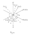
- Figure 4 shows the relationship between the axes of the elements of the liquid crystal display device of Figure 3.
- R46a and R46b respectively designate the rubbing directions of the upper electrode base 36a and the lower electrode base 36b
- T4 designates the direction and angle of twist of the liquid crystal molecules in the liquid crystal cell 34 from top to bottom as viewed in Figure 3
- P41 and P42 respectively designate the directions of the axes of polarisation of the upper and lower polarising plates 31, 32
- the line A-A′ represents the direction of observation
- ⁇ 41 designates the angle between the direction of observation A-A′ and the rubbing direction R46a of the upper electrode base 36a
- ⁇ 42 designates the angle between the direction of observation A-A′ and the rubbing direction R46b of the lower electrode base 36b.
- the angles ⁇ 41 and ⁇ 42 are approximately equal to one another.
- the retardation value of the optically anisotropic member and the relationship between the axes are set for the liquid crystal display device used in the STN mode so as to improve contrast and to enable black and white display.
- contrast has been improved in this manner to achieve a nearly full black and white display in comparison with ordinary STN devices, viewing angle characteristics have not been considered.
- the present invention seeks to provide a liquid crystal display device having improved viewing angle characteristics as well as high black and white display contrast.
- a liquid crystal display device comprising: a pair of polarising plates; a liquid crystal cell having a pair of electrode plates and a twist oriented nematic liquid crystal material interposed therebetween; and at least one layer of an optically anisotropic material, the liquid crystal cell and layer or layers of optically anisotropic material being sandwiched between said polarising plates, characterised in that the direction of the optical axis of the or at least one of the layers of optically anisotropic material is set at an angle of 0° to 30° or 60° to 90° to a direction of observation.
- At least one layer of optically anisotropic material is disposed between the liquid crystal cell and one of the polarising plates and at least one layer of optically anisotropic material is disposed between the liquid crystal cell and the other polarising plate, the angle between the direction of observation and the direction of the optical axis of at least one of said layers of optically anisotropic material being 0° to 30° or 60° to 90°.
- a liquid crystal display device comprising: a pair of polarising plates; a liquid crystal cell having a pair of electrode plates and a twist oriented nematic liquid crystal material interposed therebetween; and a plurality of layers of an optically anisotropic material, the liquid crystal cell and the layers of optically anisotropic material being sandwiched between said polarising plates, characterised in that at least one layer of optically anisotropic material is disposed between the liquid crystal cell and one of the polarising plates, and at least one layer of optically anisotropic substance is disposed between the liquid crystal cell and the other polarising plate, the angle between the direction of observation and the direction of a bisector between the optical axes of said layers of optically anisotropic substance adjacent to said liquid crystal cell being 0° to 30° or 60° to 90°.
- the direction of observation is defined as described below with reference to Figure 5.
- the direction of observation is a direction in which the display is viewed most frequently during use of the liquid crystal display device. Ordinarily, it coincides with the direction A-A′ perpendicular to the lengthwise direction of the liquid crystal display device, as shown in Figure 5.
- a designates the angle between a direction OC perpendicular to the plane of the liquid crystal display device and a viewing direction OD
- ⁇ designates the angle between a direction of observation A-A′ and the direction of viewing OD′ on the plane of the liquid crystal display device.
- display viewing angle characteristics are such that the viewing angle on the front left side and the front right side with respect to the direction of observation are approximately equal to each other, and that the ranges of viewing angles are generally uniform in the horizontal direction.
- Examination was made of a liquid crystal cell and a layer of optically anisotropic substance sandwiched between two polarising plates. The purpose of the examination was to see how the viewing angle characteristics were influenced by the directions of the polarising axes of the polarising plates, the rubbing directions of the liquid crystal cell, and the angles between the axes, by using equal contrast curves (the relationship between values of the angles a and ⁇ shown in Figure 5, at which a given contrast is obtained). It was found from this examination that the direction of the centre line on which equal contrast curves are generally symmetric, approximately coincides with the direction of the optical axis of the optically anisotropic member.
- FIG. 1 shows schematically a cross section of one embodiment of a liquid crystal display device according to the present invention.
- An optically anisotropic member 3 and a liquid crystal cell 4 are sandwiched between upper and lower polarising plates 1, 2.
- the liquid crystal cell 4 comprises a nematic liquid crystal material 7 retained between an upper electrode base 6a having electrodes 5a formed on its lower surface and a lower electrode base 6b having electrodes 5b formed on its upper surface.
- the nematic liquid crystal 7 is twist oriented by rubbing the opposed upper and lower electrode bases 6a, 6b.
- Spacers 8 are interposed between the upper and lower electrode bases 6a, 6b to retain the nematic liquid crystal 7 therebetween while maintaining a constant liquid crystal layer thickness. Spacing maintaining members such as glass fibres or glass balls may be disposed between the electrode bases 6a, 6b in order to maintain the liquid crystal layer thickness constant.
- the means for orienting liquid crystal molecules of a liquid crystal display device according to the present invention is not limited to rubbing. However, for convenience, the direction in which the major axes of the liquid crystal molecules adjacent to each of the electrode bases will hereinafter be referred to as “the rubbing direction”.
- a polycarbonate member uni-axially orientated is used as the optically anisotropic member 3 which will hereinafter be referred to as "the phase difference plate”.
- Figure 2 shows the relationship between the axes of the elements of the liquid crystal display device shown in Figure 1.
- R6a, R6b respectively designate the rubbing directions of the upper electrode base 6a and the lower electrode base 6b
- T designates the direction and angle of twist of the liquid crystal molecules in the liquid crystal cell 4 from top to bottom as viewed in Figure 1
- P1 and P2 respectively designate the directions of the axes of polarisation of the upper and lower polarising plates 1
- the line A-A′ represents the direction of observation
- ⁇ 1 designates the angle between the direction of observation A-A′ and the direction P1 of the polarisation axis of the upper polarising plate
- ⁇ 2 designates the angle between the direction of observation A-A′ and the direction P2 of the polarisation axis of the lower polarising plate
- ⁇ 3 designates the angle between the direction of observation A-A′ and the direction R3 of the optical axis of the phase difference plate 3
- ⁇ 4 designates the angle between the direction of observation
- the polarisation axes are used in this embodiment of the present invention but similar effects can also be obtained when absorption axes are used as an alternative.
- the liquid crystal display device of Figure 1 will be described with respect to a negative display mode (in which the display is dark when no voltage is applied across the electrodes 5a, 5b and bright when a voltage is applied). However, the same effects can be obtained in a positive display mode (in which the display is bright when no voltage is applied across the electrodes 5a, 5b, and dark when a voltage is applied).
- the refractive index anisotropy ⁇ n of the phase difference plate 3 is defined as ⁇ nf
- the thickness of the phase difference plate is defined as df .
- Examples 11 to 12 are provided in Table 2.
- Table 2 also shows Comparative Examples 4 to 6.
- FIG. 7 illustrates schematically another embodiment of a liquid crystal display device according to the present invention.
- Two phase difference plates 73a, 73b are interposed between the liquid crystal cell 4 and the upper polarising plate 1, the phase difference plate 73a being adjacent to the liquid crystal cell 4 and the phase difference plate 73b being adjacent the polarising plate 1.
- Figure 8 shows the relationship between the axes of the elements of the liquid crystal display device of Figure 7.
- the direction R83a of the optical axis of the phase difference plate 73a is at an angle ⁇ 83a to the direction of observation A-A′
- the direction ⁇ 83b of the optical axis of the phase difference plate 73b is at an angle ⁇ 83b to the observation direction A-A′.
- Table 3 shows Examples 21 and 22 of liquid crystal display devices according to this embodiment of the present invention.
- the liquid crystal display device of Example 22 is also sufficiently easy to view, although the degree of symmetry of the equal contrast curves is slightly lower than that of Example 21.
- FIG. 9 illustrates a third embodiment of a liquid crystal display device according to the present invention.
- This liquid crystal display device comprises an upper phase difference plate 93a interposed between the liquid crystal cell 4 and the upper polarising plate 1, while a lower phase difference plate 93b is interposed between the liquid crystal cell 4 and the lower polarising plate 2.
- Figure 10 shows the relationship between the axes of the elements of the liquid crystal display device of Figure 9.
- the direction R103a of the optical axis of the upper phase difference plate 93a is at an angle ⁇ 103a from the direction of observation A-A′
- the direction R103b of the optical axis of the lower phase difference plate 93b is at an angle of ⁇ 103b from the direction of observation A-A′.
- Table 4 shows Examples 23 and 24 of this display device.
- phase difference plate is disposed on either side of the liquid crystal cell
- equal contrast curves are symmetric so that the display is easy to view if the angle between the direction of observation and the direction of a bisector between the directions of the optical axes of the phase difference plates adjacent to the liquid crystal cell is set to 0° to 30° or 60° to 90°.
- the material of the optically anisotropic member 3 in a liquid crystal display device according to the present invention is not limited to polycarbonate, and it may be formed by uni-axially stretching a sheet of material selected from monomers or polymers of diacetyle cellulose, polyamide, polyimide, polyether sulphone, polysulphone, polyolefin, polyethylene, polyethylene tetraphthalate, polyvinyl alcohol, acryl and polymethyl methacrylate.
Abstract
Description
- This invention relates to liquid crystal display devices.
- A liquid crystal display device of the super twisted nematic (STN) type has a uni-axial optically anisotropic member (e.g. an oriented high polymer sheet) interposed between two polarising plates to improve display quality.
- Figure 3 is a cross sectional view of such a conventional liquid crystal display device. As illustrated, an optically
anisotropic member 33 and aliquid crystal cell 34 are sandwiched between upper andlower polarising plates liquid crystal cell 34 consists of a nematicliquid crystal material 37 retained between an upper electrode base 36a having electrodes 35a formed on its lower surface and a lower electrode base36b having electrodes 35b formed on its upper surface. The nematicliquid crystal material 37 is twist oriented by rubbing the opposed upper and lower electrode bases 36a, 36b. Spacers are interposed between the upper and lower electrode bases 36a, 36b to retain the nematicliquid crystal material 37 therebetween while maintaining a constant liquid crystal layer thickness. - Figure 4 shows the relationship between the axes of the elements of the liquid crystal display device of Figure 3. In Figure 4, R46a and R46b respectively designate the rubbing directions of the upper electrode base 36a and the lower electrode base 36b, T4 designates the direction and angle of twist of the liquid crystal molecules in the
liquid crystal cell 34 from top to bottom as viewed in Figure 3, P41 and P42 respectively designate the directions of the axes of polarisation of the upper andlower polarising plates - In a conventional liquid crystal display device of the type illustrated in Figure 3, the retardation value of the optically anisotropic member and the relationship between the axes, are set for the liquid crystal display device used in the STN mode so as to improve contrast and to enable black and white display. Although contrast has been improved in this manner to achieve a nearly full black and white display in comparison with ordinary STN devices, viewing angle characteristics have not been considered.
- The present invention seeks to provide a liquid crystal display device having improved viewing angle characteristics as well as high black and white display contrast.
- According to one aspect of the present invention there is provided a liquid crystal display device comprising: a pair of polarising plates; a liquid crystal cell having a pair of electrode plates and a twist oriented nematic liquid crystal material interposed therebetween; and at least one layer of an optically anisotropic material, the liquid crystal cell and layer or layers of optically anisotropic material being sandwiched between said polarising plates, characterised in that the direction of the optical axis of the or at least one of the layers of optically anisotropic material is set at an angle of 0° to 30° or 60° to 90° to a direction of observation.
- In one embodiment there is a single layer of optically anisotropic material.
- In another embodiment there are at least two layers of optically anisotropic material disposed between the liquid crystal cell and one of the polarising plates, the angle between the direction of observation and the direction of the optical axis of the layer of optically anisotropic material adjacent to the liquid crystal cell being 0° to 30° or 60° to 90°.
- In a further embodiment at least one layer of optically anisotropic material is disposed between the liquid crystal cell and one of the polarising plates and at least one layer of optically anisotropic material is disposed between the liquid crystal cell and the other polarising plate, the angle between the direction of observation and the direction of the optical axis of at least one of said layers of optically anisotropic material being 0° to 30° or 60° to 90°.
- According to another aspect of the present invention there is provided a liquid crystal display device comprising: a pair of polarising plates; a liquid crystal cell having a pair of electrode plates and a twist oriented nematic liquid crystal material interposed therebetween; and a plurality of layers of an optically anisotropic material, the liquid crystal cell and the layers of optically anisotropic material being sandwiched between said polarising plates, characterised in that at least one layer of optically anisotropic material is disposed between the liquid crystal cell and one of the polarising plates, and at least one layer of optically anisotropic substance is disposed between the liquid crystal cell and the other polarising plate, the angle between the direction of observation and the direction of a bisector between the optical axes of said layers of optically anisotropic substance adjacent to said liquid crystal cell being 0° to 30° or 60° to 90°.
- The direction of observation is defined as described below with reference to Figure 5. The direction of observation is a direction in which the display is viewed most frequently during use of the liquid crystal display device. Ordinarily, it coincides with the direction A-A′ perpendicular to the lengthwise direction of the liquid crystal display device, as shown in Figure 5. In Figure 5, a designates the angle between a direction OC perpendicular to the plane of the liquid crystal display device and a viewing direction OD, and β designates the angle between a direction of observation A-A′ and the direction of viewing OD′ on the plane of the liquid crystal display device.
- The invention is illustrated, merely by way of example, in the accompanying drawings, in which:-
- Figure 1 is a schematic cross sectional view of one embodiment of a liquid crystal display device according to the present invention;
- Figure 2 is a diagram of the relationship between various axes of the liquid crystal display device of Figure 1;
- Figure 3 is a schematic cross sectional view of a conventional liquid crystal display device;
- Figure 4 is a diagram of the relationship between various axes of the conventional liquid crystal display device of Figure 3;
- Figure 5 is a diagram explaining direction of observation;
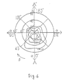
- Figure 6 is a diagram of equal contrast curves of Example 1;
- Figure 7 is a schematic cross sectional view of another embodiment of a liquid crystal display device according to the present invention;
- Figure 8 is a diagram of the relationship between various axes of the liquid crystal display device of Figure 7;
- Figure 9 is a schematic cross sectional view of a third embodiment of a liquid crystal display device according to the present invention; and
- Figure 10 is a diagram of the relationship between various axes of the liquid crystal display device of Figure 9.
- Throughout the drawings like parts have been designated by the same reference numerals.
- It is desirable that, in a liquid crystal display device, display viewing angle characteristics are such that the viewing angle on the front left side and the front right side with respect to the direction of observation are approximately equal to each other, and that the ranges of viewing angles are generally uniform in the horizontal direction. Examination was made of a liquid crystal cell and a layer of optically anisotropic substance sandwiched between two polarising plates. The purpose of the examination was to see how the viewing angle characteristics were influenced by the directions of the polarising axes of the polarising plates, the rubbing directions of the liquid crystal cell, and the angles between the axes, by using equal contrast curves (the relationship between values of the angles a and β shown in Figure 5, at which a given contrast is obtained). It was found from this examination that the direction of the centre line on which equal contrast curves are generally symmetric, approximately coincides with the direction of the optical axis of the optically anisotropic member.
- Figure 1 shows schematically a cross section of one embodiment of a liquid crystal display device according to the present invention. An optically
anisotropic member 3 and aliquid crystal cell 4 are sandwiched between upper and lowerpolarising plates liquid crystal cell 4 comprises a nematicliquid crystal material 7 retained between an upper electrode base6a having electrodes 5a formed on its lower surface and a lower electrode base6b having electrodes 5b formed on its upper surface. The nematicliquid crystal 7 is twist oriented by rubbing the opposed upper and lower electrode bases 6a, 6b.Spacers 8 are interposed between the upper and lower electrode bases 6a, 6b to retain the nematicliquid crystal 7 therebetween while maintaining a constant liquid crystal layer thickness. Spacing maintaining members such as glass fibres or glass balls may be disposed between the electrode bases 6a, 6b in order to maintain the liquid crystal layer thickness constant. - The means for orienting liquid crystal molecules of a liquid crystal display device according to the present invention is not limited to rubbing. However, for convenience, the direction in which the major axes of the liquid crystal molecules adjacent to each of the electrode bases will hereinafter be referred to as "the rubbing direction". A polycarbonate member uni-axially orientated is used as the optically
anisotropic member 3 which will hereinafter be referred to as "the phase difference plate". - Figure 2 shows the relationship between the axes of the elements of the liquid crystal display device shown in Figure 1. In Figure 2, R6a, R6b respectively designate the rubbing directions of the upper electrode base 6a and the lower electrode base 6b, T designates the direction and angle of twist of the liquid crystal molecules in the
liquid crystal cell 4 from top to bottom as viewed in Figure 1, P1 and P2 respectively designate the directions of the axes of polarisation of the upper andlower polarising plates polarising plate 1, ϑ2 designates the angle between the direction of observation A-A′ and the direction P2 of the polarisation axis of the lowerpolarising plate 2, ϑ3 designates the angle between the direction of observation A-A′ and the direction R3 of the optical axis of thephase difference plate 3, and ϑ4 designates the angle between the direction of observation A-A′ and the rubbing direction R6a of the upper electrode base 6a. It is assumed that the value of each angle ϑ1, ϑ2, ϑ3, ϑ4 is positive when measured clockwise from the direction of observation A-A′. - The polarisation axes are used in this embodiment of the present invention but similar effects can also be obtained when absorption axes are used as an alternative.
- The liquid crystal display device of Figure 1 will be described with respect to a negative display mode (in which the display is dark when no voltage is applied across the
electrodes electrodes phase difference plate 3 is defined as Δnf, and the thickness of the phase difference plate is defined as df. - When in a liquid crystal display device shown in Figure 1 the product Δ n·d of the refractive index anisotropy Δ n of the
liquid crystal material 7 of theliquid crystal cell 4 and the thickness d of the layer of theliquid crystal material 7 is 0.9 µm, the liquid crystal material is twisted counter-clockwise by a twist angle T = 240°, the product Δ nf·df of the refractive index anisotropy Δ nf and the thickness df of thephase difference plate 3 is 0.55 µm, ϑ1 = -45°, ϑ2 = -15°, ϑ3 = 0° and ϑ4 = 90°, equal contrast curves such as those shown in Figure 6 are exhibited. These curves are symmetric with respect to the direction of observation A-A′, and the display is easy to view under these conditions. Table 1 shows Examples 1 to 10 of the present invention together with Comparative Examples 1 to 3, Example 1 satisfying the above conditions.
- In Table 1, symbols ⓞ, ○, X are used to indicate whether or not the contrast curves are generally symmetrical with respect to the direction of observation so that the display is easy to view: ⓞ indicates that the result is very good, ○ indicates that it is good, and X indicates that it is poor.
- As will be appreciated from Table 1, to realise an easy to view display in which the contrast distribution is generally symmetric with respect to the direction of observation A-A′, it is desirable to set the angle ϑ3 between the direction of the optical axis of the
phase difference plate 3 and the direction of observation A-A′ to between 0° to 30°. - To obtain a display in which the axis of symmetry coincides with a direction perpendicular to the direction of observation A-A′, Examples 11 to 12 are provided in Table 2. Table 2 also shows Comparative Examples 4 to 6.

- As in Table 1, in Table 2 symbols ⓞ, ○, X are used to indicate whether or not the contrast curves are generally symmetrical with respect to a centre line perpendicular to the direction of observation; ⓞ indicates that the result is very good; ○ indicates that it is good, and X indicates that it is poor.
- As will be appreciated from Table 2, to realise an easy to view display in which the contrast distribution is generally symmetric with respect to the line perpendicular to the direction of observation A-A′, it is desirable to set the angle ϑ3 between the direction of the optical axis of the
phase difference plate 3 and the direction of observation to 60° to 90°. - Figure 7 illustrates schematically another embodiment of a liquid crystal display device according to the present invention. Two phase difference plates 73a, 73b are interposed between the
liquid crystal cell 4 and theupper polarising plate 1, the phase difference plate 73a being adjacent to theliquid crystal cell 4 and the phase difference plate 73b being adjacent the polarisingplate 1. - Figure 8 shows the relationship between the axes of the elements of the liquid crystal display device of Figure 7. The direction R83a of the optical axis of the phase difference plate 73a is at an angle ϑ83a to the direction of observation A-A′, and the direction ϑ83b of the optical axis of the phase difference plate 73b is at an angle ϑ83b to the observation direction A-A′. Table 3 shows Examples 21 and 22 of liquid crystal display devices according to this embodiment of the present invention.

- With respect to Example 21, the relationship between the axes of Figure 8 is as follows: Δ n·d of the
liquid crystal cell 4 is 0.90 µm, the liquid crystal material is twisted counter-clockwise by a twist angle T = 240°, Δ nf·df of the phase difference plate 73a is 0.40 µm, Δ nf·df of the phase difference plate 73b is 0.45 µm, ϑ1 = -20°, ϑ2 = -70°, ϑ83a = 0°, ϑ83b = 50°, and ϑ4 = -80°. Under these conditions, equal contrast curves are generally symmetric with respect to the direction of observation A-A′, and the display is easy to view. The liquid crystal display device of Example 22 is also sufficiently easy to view, although the degree of symmetry of the equal contrast curves is slightly lower than that of Example 21. - Figure 9 illustrates a third embodiment of a liquid crystal display device according to the present invention. This liquid crystal display device comprises an upper
phase difference plate 93a interposed between theliquid crystal cell 4 and theupper polarising plate 1, while a lower phase difference plate 93b is interposed between theliquid crystal cell 4 and thelower polarising plate 2. - Figure 10 shows the relationship between the axes of the elements of the liquid crystal display device of Figure 9. The direction R103a of the optical axis of the upper
phase difference plate 93a is at an angle ϑ103a from the direction of observation A-A′, and the direction R103b of the optical axis of the lower phase difference plate 93b is at an angle of ϑ103b from the direction of observation A-A′. Table 4 shows Examples 23 and 24 of this display device.
- With respect to Example 23, the relationship between the axes is as follows: Δ n·d of the
liquid crystal cell 4 is 0.90 µm, the liquid crystal material is twisted counter-clockwise by a twist angle T = 240°, Δ nf·df of the upperphase difference plate 93a is 0.42 µm, Δ nf·df of the lower phase difference plate 93b is 0.42 µm, ϑ1 = -10°, ϑ2 = -80°, ϑ103a = 30°, ϑ103b = -30° and ϑ4 = -60°. Under these conditions, equal contrast curves are generally symmetric with respect to the direction of observation and the display is easy to view. In the case of Example 24 shown in Table 4, equal contrast curves are generally symmetric so that the display is also easy to view. - From these results, it will be appreciated that where a plurality of phase difference plates are disposed on one side of the liquid crystal cell, equal contrast curves are symmetric so that the display is easy to view if at least the angle between the direction of observation and the direction of the optical axis of the phase difference plate adjacent to the liquid crystal cell is set to 0° to 30° or 60° to 90°.
- It will also be appreciated that where at least one phase difference plate is disposed on either side of the liquid crystal cell, equal contrast curves are symmetric so that the display is easy to view if the angle between the direction of observation and the direction of a bisector between the directions of the optical axes of the phase difference plates adjacent to the liquid crystal cell is set to 0° to 30° or 60° to 90°.
- The material of the optically
anisotropic member 3 in a liquid crystal display device according to the present invention is not limited to polycarbonate, and it may be formed by uni-axially stretching a sheet of material selected from monomers or polymers of diacetyle cellulose, polyamide, polyimide, polyether sulphone, polysulphone, polyolefin, polyethylene, polyethylene tetraphthalate, polyvinyl alcohol, acryl and polymethyl methacrylate.
Claims (5)
- A liquid crystal display device comprising: a pair of polarising plates (1, 2); a liquid crystal cell (4) having a pair of electrode plates (6a, 6b) and a twist oriented nematic liquid crystal material (7) interposed therebetween; and at least one layer (3; 73a, 73b; 93a, 93b) of an optically anisotropic material, the liquid crystal cell and layer or layers of optically anisotropic material being sandwiched between said polarising plates, characterised in that the direction of the optical axis (R3; R83a, R83b; R103a, R103b) of the or at least one of the layers of optically anisotropic material is set at an angle of 0° to 30° or 60° to 90° to a direction of observation (A-A′).
- A liquid crystal display device as claimed in claim 1 characterised in that there is a single layer (3) of optically anisotropic material.
- A liquid crystal display device as claimed in claim 1 characterised in that there are at least two layers (73a, 73b) of optically anisotropic material disposed between the liquid crystal cell (4) and one of the polarising plates (1, 2), the angle between the direction of observation (A-A′) and the direction of the optical axis (R83a) of the layer (73a) of optically anisotropic material adjacent to the liquid crystal cell being 0° to 30° or 60° to 90°.
- A liquid crystal display device as claimed in claim 1 characterised in that at least one layer (93a) of optically anisotropic material is disposed between the liquid crystal cell (4) and one of the polarising plates (1) and at least one layer (93b) of optically anisotropic material is disposed between the liquid crystal cell (4) and the other polarising plate (2), the angle between the direction of observation (A-A′) and the direction of the optical axis (R103a, R103b) of at least one of said layers of optically anisotropic material being 0° to 30° or 60° to 90°.
- A liquid crystal display device comprising: a pair of polarising plates (1, 2); a liquid crystal cell (4) having a pair of electrode plates (6a, 6b) and a twist oriented nematic liquid crystal material (7) interposed therebetween; and a plurality of layers (93a, 93b) of an optically anisotropic material, the liquid crystal cell and the layers of optically anisotropic material being sandwiched between said polarising plates, characterised in that at least one layer (93a) of optically anisotropic material is disposed between the liquid crystal cell (4) and one of the polarising plates (1), and at least one layer (93b) of optically anisotropic substance is disposed between the liquid crystal cell (4) and the other polarising plate (2), the angle between the direction of observation (A-A′) and the direction of a bisector between the optical axes (R103a, R103b) of said layers of optically anisotropic substance adjacent to said liquid crystal cell being 0° to 30° or 60° to 90°.
Applications Claiming Priority (2)
| Application Number | Priority Date | Filing Date | Title |
|---|---|---|---|
| JP02093667A JP3084724B2 (en) | 1990-04-09 | 1990-04-09 | Liquid crystal display |
| JP93667/90 | 1990-04-09 |
Publications (2)
| Publication Number | Publication Date |
|---|---|
| EP0452062A2 true EP0452062A2 (en) | 1991-10-16 |
| EP0452062A3 EP0452062A3 (en) | 1992-07-01 |
Family
ID=14088751
Family Applications (1)
| Application Number | Title | Priority Date | Filing Date |
|---|---|---|---|
| EP19910303065 Withdrawn EP0452062A3 (en) | 1990-04-09 | 1991-04-08 | Liquid crystal display device |
Country Status (4)
| Country | Link |
|---|---|
| US (1) | US5212819A (en) |
| EP (1) | EP0452062A3 (en) |
| JP (1) | JP3084724B2 (en) |
| KR (1) | KR910018835A (en) |
Cited By (3)
| Publication number | Priority date | Publication date | Assignee | Title |
|---|---|---|---|---|
| EP0472111A2 (en) * | 1990-08-23 | 1992-02-26 | Sel Semiconductor Energy Laboratory Co., Ltd. | A liquid crystal electro-optic device |
| GB2272779A (en) * | 1992-11-18 | 1994-05-25 | Fuji Photo Film Co Ltd | Optically anisotropic element |
| EP0646829A1 (en) * | 1993-09-22 | 1995-04-05 | Fuji Photo Film Co., Ltd. | Liquid crystal display |
Families Citing this family (44)
| Publication number | Priority date | Publication date | Assignee | Title |
|---|---|---|---|---|
| US5303075A (en) * | 1990-04-09 | 1994-04-12 | Seiko Epson Corporation | Liquid crystal display with phase difference plate having particular .DELTA.Δnxd at 45° angle to surface |
| EP0470817A3 (en) * | 1990-08-09 | 1992-11-25 | Seiko Epson Corporation | Liquid crystal electro-optical device |
| JPH0611710A (en) * | 1992-04-27 | 1994-01-21 | Kanegafuchi Chem Ind Co Ltd | Liquid crystal display element |
| DE4339395B4 (en) * | 1992-11-18 | 2007-11-29 | Fujifilm Corp. | Optically anisotropic element and method of making the same |
| US5910854A (en) | 1993-02-26 | 1999-06-08 | Donnelly Corporation | Electrochromic polymeric solid films, manufacturing electrochromic devices using such solid films, and processes for making such solid films and devices |
| US5724112A (en) * | 1994-03-28 | 1998-03-03 | Casio Computer Co., Ltd. | Color liquid crystal apparatus |
| US5668663A (en) * | 1994-05-05 | 1997-09-16 | Donnelly Corporation | Electrochromic mirrors and devices |
| TW428116B (en) * | 1994-05-18 | 2001-04-01 | Matsushita Electric Ind Co Ltd | Liquid crystal display element and laminated phase difference plate used for the same |
| JPH08152618A (en) * | 1994-11-29 | 1996-06-11 | Alps Electric Co Ltd | Color liquid crystal display device |
| JPH08194204A (en) * | 1995-01-20 | 1996-07-30 | Hitachi Ltd | Liquid crystal display device |
| WO1996026462A1 (en) * | 1995-02-23 | 1996-08-29 | Philips Electronics N.V. | Liquid crystal display device and retardation foil |
| US6891563B2 (en) | 1996-05-22 | 2005-05-10 | Donnelly Corporation | Vehicular vision system |
| JP3284169B2 (en) * | 1995-10-13 | 2002-05-20 | シャープ株式会社 | Birefringence control type liquid crystal display |
| US6226061B1 (en) * | 1997-03-25 | 2001-05-01 | Sharp Kabushiki Kaisha | Liquid crystal display device having phase different plates |
| JP3678540B2 (en) * | 1997-05-27 | 2005-08-03 | 新日本石油株式会社 | Liquid crystal display element |
| US6172613B1 (en) | 1998-02-18 | 2001-01-09 | Donnelly Corporation | Rearview mirror assembly incorporating vehicle information display |
| US6326613B1 (en) | 1998-01-07 | 2001-12-04 | Donnelly Corporation | Vehicle interior mirror assembly adapted for containing a rain sensor |
| US8294975B2 (en) | 1997-08-25 | 2012-10-23 | Donnelly Corporation | Automotive rearview mirror assembly |
| US6124886A (en) * | 1997-08-25 | 2000-09-26 | Donnelly Corporation | Modular rearview mirror assembly |
| US6445287B1 (en) | 2000-02-28 | 2002-09-03 | Donnelly Corporation | Tire inflation assistance monitoring system |
| US8288711B2 (en) | 1998-01-07 | 2012-10-16 | Donnelly Corporation | Interior rearview mirror system with forwardly-viewing camera and a control |
| US6329925B1 (en) | 1999-11-24 | 2001-12-11 | Donnelly Corporation | Rearview mirror assembly with added feature modular display |
| US6693517B2 (en) | 2000-04-21 | 2004-02-17 | Donnelly Corporation | Vehicle mirror assembly communicating wirelessly with vehicle accessories and occupants |
| US6477464B2 (en) | 2000-03-09 | 2002-11-05 | Donnelly Corporation | Complete mirror-based global-positioning system (GPS) navigation solution |
| WO2001064481A2 (en) | 2000-03-02 | 2001-09-07 | Donnelly Corporation | Video mirror systems incorporating an accessory module |
| US7195381B2 (en) | 2001-01-23 | 2007-03-27 | Donnelly Corporation | Vehicle interior LED lighting system |
| US7167796B2 (en) | 2000-03-09 | 2007-01-23 | Donnelly Corporation | Vehicle navigation system for use with a telematics system |
| US7370983B2 (en) | 2000-03-02 | 2008-05-13 | Donnelly Corporation | Interior mirror assembly with display |
| US7581859B2 (en) | 2005-09-14 | 2009-09-01 | Donnelly Corp. | Display device for exterior rearview mirror |
| US7255451B2 (en) | 2002-09-20 | 2007-08-14 | Donnelly Corporation | Electro-optic mirror cell |
| US6918674B2 (en) | 2002-05-03 | 2005-07-19 | Donnelly Corporation | Vehicle rearview mirror system |
| US7329013B2 (en) | 2002-06-06 | 2008-02-12 | Donnelly Corporation | Interior rearview mirror system with compass |
| AU2003237424A1 (en) | 2002-06-06 | 2003-12-22 | Donnelly Corporation | Interior rearview mirror system with compass |
| US7310177B2 (en) | 2002-09-20 | 2007-12-18 | Donnelly Corporation | Electro-optic reflective element assembly |
| EP1543358A2 (en) | 2002-09-20 | 2005-06-22 | Donnelly Corporation | Mirror reflective element assembly |
| US7289037B2 (en) | 2003-05-19 | 2007-10-30 | Donnelly Corporation | Mirror assembly for vehicle |
| US7446924B2 (en) | 2003-10-02 | 2008-11-04 | Donnelly Corporation | Mirror reflective element assembly including electronic component |
| US7308341B2 (en) | 2003-10-14 | 2007-12-11 | Donnelly Corporation | Vehicle communication system |
| US7626749B2 (en) | 2005-05-16 | 2009-12-01 | Donnelly Corporation | Vehicle mirror assembly with indicia at reflective element |
| CN101535087B (en) | 2005-11-01 | 2013-05-15 | 唐纳利公司 | Interior rearview mirror with display |
| EP2099869B1 (en) | 2006-10-31 | 2013-05-01 | Sensient Colors Inc. | Modified pigments and methods for making and using the same |
| EP3483222A3 (en) | 2007-08-23 | 2019-08-07 | Sensient Colors LLC | Self-dispersed pigments and methods for making and using the same |
| US8154418B2 (en) | 2008-03-31 | 2012-04-10 | Magna Mirrors Of America, Inc. | Interior rearview mirror system |
| CN102858886A (en) | 2009-04-07 | 2013-01-02 | 森馨颜色有限责任公司 | Self-dispersing particles and methods for making and using the same |
Citations (3)
| Publication number | Priority date | Publication date | Assignee | Title |
|---|---|---|---|---|
| EP0350063A2 (en) * | 1988-07-08 | 1990-01-10 | Kabushiki Kaisha Toshiba | Liquid crystal display device |
| EP0350075A2 (en) * | 1988-07-08 | 1990-01-10 | Kabushiki Kaisha Toshiba | Liquid crystal display device |
| EP0352724A1 (en) * | 1988-07-27 | 1990-01-31 | Kabushiki Kaisha Toshiba | A liquid crystal display device |
Family Cites Families (8)
| Publication number | Priority date | Publication date | Assignee | Title |
|---|---|---|---|---|
| JPS53123944A (en) * | 1977-04-05 | 1978-10-28 | Toyo Boseki | Light bending film |
| GB2171549B (en) * | 1985-02-15 | 1988-05-18 | Citizen Watch Co Ltd | Liquid crystal display device |
| FR2580105A1 (en) * | 1985-04-04 | 1986-10-10 | Commissariat Energie Atomique | Display cell with nematic liquid crystals of the reflective type with electrically-controlled birefringence making it possible to improve the illumination of the display |
| FR2595156B1 (en) * | 1986-02-28 | 1988-04-29 | Commissariat Energie Atomique | LIQUID CRYSTAL CELL USING ELECTRICALLY CONTROLLED BIREFRINGENCE EFFECT AND METHODS OF MANUFACTURING THE CELL AND A UNIAXIC NEGATIVE ANISOTROPY ANISOTROPY MEDIUM FOR USE THEREIN |
| DE3752219T2 (en) * | 1986-05-19 | 1999-02-18 | Seiko Epson Corp | Liquid crystal display device |
| FR2613566B1 (en) * | 1987-04-06 | 1989-06-09 | Commissariat Energie Atomique | ACTIVE MATRIX SCREEN FOR COLOR DISPLAY OF TELEVISION IMAGES, CONTROL SYSTEM AND METHOD FOR MANUFACTURING SAID SCREEN |
| DE3884291T2 (en) * | 1987-06-30 | 1994-03-31 | Sumitomo Chemical Co | Phase-retarding polymer films and polarizing components. |
| JP3071204B2 (en) * | 1989-02-10 | 2000-07-31 | 株式会社リコー | Liquid crystal display device |
-
1990
- 1990-04-09 JP JP02093667A patent/JP3084724B2/en not_active Expired - Lifetime
-
1991
- 1991-04-03 KR KR1019910005348A patent/KR910018835A/en not_active Application Discontinuation
- 1991-04-08 EP EP19910303065 patent/EP0452062A3/en not_active Withdrawn
- 1991-04-09 US US07/683,419 patent/US5212819A/en not_active Expired - Lifetime
Patent Citations (3)
| Publication number | Priority date | Publication date | Assignee | Title |
|---|---|---|---|---|
| EP0350063A2 (en) * | 1988-07-08 | 1990-01-10 | Kabushiki Kaisha Toshiba | Liquid crystal display device |
| EP0350075A2 (en) * | 1988-07-08 | 1990-01-10 | Kabushiki Kaisha Toshiba | Liquid crystal display device |
| EP0352724A1 (en) * | 1988-07-27 | 1990-01-31 | Kabushiki Kaisha Toshiba | A liquid crystal display device |
Non-Patent Citations (1)
| Title |
|---|
| 1989 SID INTERNATIONAL SYMPOSIUM, DIGEST OF TECHNICAL PAPERS, vol. XX, 16 May 1989, BALTIMORE, US; pages 390 - 393; M.OHGAWARA ET AL.: 'A Color STN Display with Two Retardation Compensating Films' * |
Cited By (6)
| Publication number | Priority date | Publication date | Assignee | Title |
|---|---|---|---|---|
| EP0472111A2 (en) * | 1990-08-23 | 1992-02-26 | Sel Semiconductor Energy Laboratory Co., Ltd. | A liquid crystal electro-optic device |
| EP0472111A3 (en) * | 1990-08-23 | 1992-07-01 | Sel Semiconductor Energy Laboratory Co., Ltd. | A liquid crystal electro-optic device |
| US5179458A (en) * | 1990-08-23 | 1993-01-12 | Semiconductor Energy Laboratory Co., Ltd. | Liquid crystal electro-optic device with particular relationship between retardation film drawing direction and substrate edge |
| GB2272779A (en) * | 1992-11-18 | 1994-05-25 | Fuji Photo Film Co Ltd | Optically anisotropic element |
| GB2272779B (en) * | 1992-11-18 | 1996-12-18 | Fuji Photo Film Co Ltd | Optically anisotropic element and method for manufacturing the same |
| EP0646829A1 (en) * | 1993-09-22 | 1995-04-05 | Fuji Photo Film Co., Ltd. | Liquid crystal display |
Also Published As
| Publication number | Publication date |
|---|---|
| KR910018835A (en) | 1991-11-30 |
| JPH03290617A (en) | 1991-12-20 |
| US5212819A (en) | 1993-05-18 |
| JP3084724B2 (en) | 2000-09-04 |
| EP0452062A3 (en) | 1992-07-01 |
Similar Documents
| Publication | Publication Date | Title |
|---|---|---|
| EP0452062A2 (en) | Liquid crystal display device | |
| US5696567A (en) | Liquid crystal display device with phase difference plate having particular Δnxd perpendicular to surface over Δnxd at 45° angle to surface | |
| KR100497441B1 (en) | Liquid crystal display device | |
| KR100697744B1 (en) | Liquid crystal display unit | |
| EP0393191B1 (en) | Liquid crystal display | |
| EP1588211B1 (en) | Vertically aligned liquid crystal display having negative compensation film | |
| EP1702233B2 (en) | In-plane switching liquid crystal display comprising compensation film for angular field of view using negative biaxial retardation film and (+) c-plate | |
| US6704083B1 (en) | Liquid crystal display including polarizing plate having polarizing directions neither parallel nor perpendicular to average alignment direction of molecules | |
| JP3407707B2 (en) | Vertical alignment type multi-domain liquid crystal display | |
| EP0424951A1 (en) | Liquid crystal display | |
| EP2485088A2 (en) | Vertically aligned liquid crystal display using a bi-axial retardation compensation film | |
| KR100233187B1 (en) | Liquid crystal display with an improved optical compensation layer | |
| EP0793134A1 (en) | Liquid crystal display having alternating cuts in electrodes | |
| KR20000009518A (en) | Vertical aligned lcd having optical visual angle | |
| US6208396B1 (en) | Normally white mode twisted nematic liquid crystal display device having improved viewing angle characteristics | |
| EP0410949B1 (en) | Liquid crystal display | |
| EP0376696A1 (en) | Optical film | |
| KR100497694B1 (en) | Liquid crystal display device | |
| US20040032561A1 (en) | Electro-optical display with in-situ polymerized columns providing alignment and structural bond between substrate | |
| JPH05157913A (en) | Phase difference film and liquid crystal display element | |
| EP0352792B1 (en) | Liquid crystal device | |
| JPS62159117A (en) | Liquid crystal display element with plastic substrate | |
| KR100247305B1 (en) | 4 domain parallel alignment lcd device | |
| JPH06174920A (en) | Optical compensation sheet and liquid crystal display element formed by using the same | |
| JPH02111918A (en) | Liquid crystal electrooptic element |
Legal Events
| Date | Code | Title | Description |
|---|---|---|---|
| PUAI | Public reference made under article 153(3) epc to a published international application that has entered the european phase |
Free format text: ORIGINAL CODE: 0009012 |
|
| AK | Designated contracting states |
Kind code of ref document: A2 Designated state(s): DE FR GB IT |
|
| PUAL | Search report despatched |
Free format text: ORIGINAL CODE: 0009013 |
|
| AK | Designated contracting states |
Kind code of ref document: A3 Designated state(s): DE FR GB IT |
|
| 17P | Request for examination filed |
Effective date: 19921229 |
|
| 17Q | First examination report despatched |
Effective date: 19940705 |
|
| STAA | Information on the status of an ep patent application or granted ep patent |
Free format text: STATUS: THE APPLICATION IS DEEMED TO BE WITHDRAWN |
|
| 18D | Application deemed to be withdrawn |
Effective date: 19950117 |