EP0452734A2 - Hands free telephone device - Google Patents
Hands free telephone device Download PDFInfo
- Publication number
- EP0452734A2 EP0452734A2 EP91105286A EP91105286A EP0452734A2 EP 0452734 A2 EP0452734 A2 EP 0452734A2 EP 91105286 A EP91105286 A EP 91105286A EP 91105286 A EP91105286 A EP 91105286A EP 0452734 A2 EP0452734 A2 EP 0452734A2
- Authority
- EP
- European Patent Office
- Prior art keywords
- circuit
- speech
- noise level
- microphone
- output
- Prior art date
- Legal status (The legal status is an assumption and is not a legal conclusion. Google has not performed a legal analysis and makes no representation as to the accuracy of the status listed.)
- Granted
Links
Images
Classifications
-
- H—ELECTRICITY
- H03—ELECTRONIC CIRCUITRY
- H03G—CONTROL OF AMPLIFICATION
- H03G3/00—Gain control in amplifiers or frequency changers without distortion of the input signal
- H03G3/20—Automatic control
- H03G3/30—Automatic control in amplifiers having semiconductor devices
- H03G3/32—Automatic control in amplifiers having semiconductor devices the control being dependent upon ambient noise level or sound level
-
- H—ELECTRICITY
- H04—ELECTRIC COMMUNICATION TECHNIQUE
- H04M—TELEPHONIC COMMUNICATION
- H04M9/00—Arrangements for interconnection not involving centralised switching
- H04M9/08—Two-way loud-speaking telephone systems with means for conditioning the signal, e.g. for suppressing echoes for one or both directions of traffic
- H04M9/10—Two-way loud-speaking telephone systems with means for conditioning the signal, e.g. for suppressing echoes for one or both directions of traffic with switching of direction of transmission by voice frequency
Landscapes
- Engineering & Computer Science (AREA)
- Signal Processing (AREA)
- Circuit For Audible Band Transducer (AREA)
- Interconnected Communication Systems, Intercoms, And Interphones (AREA)
Abstract
Description
Die Erfindung betrifft eine Schaltungsanordnung für eine Freisprecheinrichtung mit einer Sprachsteuerschaltung gemäß dem Oberbegriff des Patentanspruches 1.The invention relates to a circuit arrangement for a hands-free device with a voice control circuit according to the preamble of
Ein Freisprechapparat bietet dem Benutzer die Möglichkeit, mit einem anderen Teilnehmer zu sprechen, ohne dabei den Telefonhörer halten zu müssen, da anstelle der Sprech- und Hörkapsel des Handapparates eines üblichen Telefonapparates ein Mikrofon und ein separater Lautsprecher vorhanden sind. Dabei kann das Mikrofon und der Lautsprecher in einem Fernsprechapparat im gleichen Gehäuse untergebracht sein. Ein üblicher Freisprechapparat weist einen Sendesprechweg, einen Empfangssprechweg, eine Schaltungsanordnung zum Verbinden der Zweidrahtteilnehmerleitung mit dem Vierdrahtteilnehmerapparat sowie eine Teilnehmerschaltung auf. Im allgemeinen ist der Sendesprechweg aus einem Mikrofon, einem Mikrofonverstärker, einem schaltbaren Sendedämpfungsglied und der Sendeteilnehmerleitung aufgebaut während der Empfangssprechweg aus einem schaltbaren Empfangsdämpfungsglied und einem Ausgangsverstärker besteht, der einen Lautsprecher ansteuert. Im Freisprechbetrieb wird der Empfangssprechweg oder der Sendesprechweg in Abhängigkeit von den Amplituden der ankommenden und abgehenden Signale entdämpft. Dies erfolgt mittels einer Sprachsteuerschaltung, die die in den Sprechwegen angeordneten Dämpfungsglieder in Abhängigkeit von den in den Übertragungszweigen festgestellten Sprachpegeln derart ansteuert, daß derjenige Übertragungszweig, der den höheren Sprachpegel aufweist, entdämpft und der andere Übertragungszweig gedämpft wird.A hands-free device offers the user the opportunity to speak to another subscriber without having to hold the telephone handset, since instead of the speech and hearing capsule of the handset of a conventional telephone set, there is a microphone and a separate loudspeaker. The microphone and the loudspeaker can be accommodated in a telephone set in the same housing. A conventional hands-free device has a transmission speech path, a reception speech path, a circuit arrangement for connecting the two-wire subscriber line to the four-wire subscriber device, and a subscriber circuit. In general, the transmit speech path is made up of a microphone, a microphone amplifier, a switchable transmission attenuator and the transmitting subscriber line, while the receive speech path consists of a switchable receive attenuator and an output amplifier which drives a loudspeaker. In hands-free mode, the receive speech path or the transmit speech path is attenuated depending on the amplitudes of the incoming and outgoing signals. This is done by means of a speech control circuit which controls the attenuators arranged in the speech paths in dependence on the speech levels determined in the transmission branches in such a way that the person Transmission branch that has the higher speech level is attenuated and the other transmission branch is attenuated.
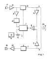
Eine Schaltungsanordnung der eingangs genannten Art, wie sie aus dem Datenbuch "Selection Guide Integrated Circuits" der Fa. TELEFUNKEN electronic, Ausgabe 1990/91, Seite 82, untere Abbildung bekannt ist, zeigt die Figur 1 als vereinfachtes Blockschaltbild. Dort wirkt eine Sprachsteuerschaltung 1 über jeweils eine Leitung auf ein Sendedämpfungsglied 6 bzw. ein Empfangsdämpfungsglied 7 ein. Dem zum Sendesprechweg gehörenden Dämpfungsglied 6 ist ein Mikrofonverstärker 15 sowie ein Mikrofon 17 vorgeschaltet und ist mit seinem Ausgang mit einer Sendeleitung 2 verbunden. Die Eingangssignale werden über eine Empfängerleitung 3 dem Dämpfungsglied 7 zugeführt, dem ein Ausgangsverstärker 14 nachgeschaltet ist, der seinerseits einen Lautsprecher 16 ansteuert. Die Sendeleitung 2 und die Empfängerleitung 3 sind zu einer Teilnehmerleitung 25 mit den Adern R und T zusammengefaßt.A circuit arrangement of the type mentioned at the outset, as is known from the data book "Selection Guide Integrated Circuits" from TELEFUNKEN electronic, edition 1990/91, page 82, lower figure, is shown in FIG. 1 as a simplified block diagram. There, a
Weiterhin wird sowohl der Sendesignalpegel auf der Sendeleitung 2 über einen logarithmischen Verstärker 10 als auch der Empfangsignalpegel auf der Empfangsleitung 3 über einen logarithmischen Verstärker 11 einem Komparator 8 zugeführt, dessen Ausgang an die Sprachsteuerschaltung 1 angeschlossen ist. Ferner wird das am Ausgang des Mikrofonverstärkers 15 zur Verfügung stehende verstärkte Mikrofonsignal einem Verstärker 9 und einem Sprachdetektor 4 zugeführt, dessen Ausgangssignale ebenfalls an die Sprachsteuerschaltung 1 weitergeleitet werden. Schließlich wird noch der Sprachsteuerschaltung 1 eine einstellbare Steuerspannung zugeführt, die an einem Widerstand 13 abgegriffen wird. Dieser Widerstand 13 ist mit einer Betriebsspannungsquelle 12 für die Schaltungsanordnung verbunden.Furthermore, both the transmit signal level on the
Der Sprachdetektor 4 dieser bekannten Schaltungsanordnung hat die Aufgabe, der Sprachsteuerschaltung 1 anzuzeigen, ob gerade gesprochen wird oder ob eine Sprechpause vorliegt. Hierbei ist unter Sprechpause nicht nur die Sprechpause eines Teilnehmers, sondern auch der Sprechwechsel von einem Teilnehmer zum anderen Teilnehmer zu verstehen.The
Die beiden Dämpfungsglieder 6 und 7 weisen drei verschiedene stabile Zustände auf:
- Zustand E:
- Empfangsweg "Ein" und Sendeweg "Aus"
- Zustand S:
- Empfangsweg "Aus" und Sendeweg "Ein"
- Zustand S:
- Beide
Dämpfungsglieder 6 und 7 sind in der Mitte zwischen der "Ein"- und der "Aus"-Stellung.
- Conditions:
- Receive path "On" and send path "Off"
- State S:
- Receive path "Off" and send path "On"
- State S:
- Both
attenuators
Hierbei ist mit "Ein" eine geringe Dämpfung und mit "Aus" eine hohe Dämpfung des Empfangsweges bzw. des Sendeweges zu verstehen.Here, "on" means low attenuation and "off" high attenuation of the reception path or the transmission path.
Zunächst sei angenommen, daß gesendet wird, wobei kein Empfangssignal auf der Empfängerleitung 3 ansteht, d. h. ein erster Teilnehmer spricht und ein zweiter Teilnehmer hört. Der Sprachdetektor 4 gibt beispielsweise ein H-Pegel aus, der der Sprachsteuerschaltung 1 anzeigt, daß gesprochen wird. Da der Signalpegel auf der Sendeleitung 2 größer ist als auf der Emfängerleitung 3, gibt der Komparator 8 eine Steuerspannung ab, die bewirkt, daß die Sprachsteuerschaltung 1 das Sendedämpfungsglied 6 auf "Ein" und das Empfangsdämpfungsglied 7 auf "Aus" schaltet, entsprechend dem Betriebszustand S.First of all, it is assumed that the transmission takes place with no reception signal present on the
Tritt nun ein Sprechwechsel ein, verstummt also der erste Teilnehmer und beginnt der zweite Teilnehmer zu sprechen, ändert der Sprachdetektor seinen Ausgangspegel. Die Sprachsteuerschaltung 1 schaltet hierauf die beiden Dämpfungsglieder 6 und 7 auf den Zustand E.If there is now a change of speech, the first participant becomes silent and the second participant begins to speak, the speech detector changes its output level. The
Sprechen jedoch beide Teilnehmer gleichzeitig, gehen die beiden Dämpfungsglieder 6 und 7 in den Betriebszustand S. Hintergrundgeräusche können ebenfalls bewirken, daß die Sprachsteuerschaltung 1 die beiden Dämpfungsglieder 6 und 7 in den Betriebszustand S schalten. Die bekannte Schaltungsanordnung weist in diesem Fall die Möglichkeit auf, die Dämpfung im Empfangssprechweg über die an dem Widerstand 13 einstellbare Steuerspannung anzuheben, um hierdurch eine Anpassung an den Pegel des Hintergrundgeräusches durch den Teilnehmer vornehmen zu lassen.However, if both participants speak at the same time, the two
Der Nachteil dieser Einstellung der Dämpfung im Empfangssprechweg in Abhängigkeit des Pegels des Hintergrundgeräusches besteht darin, daß sie nur bei länger anhaltenden, kontinuierlichen Hintergrundgeräuschen eine gewisse Anpassung an dieselben erlaubt, jedoch bei kurzfristig auftetenden oder mit hoher Dynamik ausgestatteten Störgeräuschen nicht brauchbar ist, da es für den Teilnehmer sehr umständlich ist, ständig die Dämpfung des Empfangsprechweges einzustellen.The disadvantage of this setting of the attenuation in the reception speech path as a function of the level of the background noise is that it only allows a certain adaptation to the background noise which is continuous for a longer period of time, but is not useful in the case of noise which occurs at short notice or is equipped with high dynamics, since it is not suitable for the participant is very cumbersome to constantly adjust the attenuation of the reception speech path.
Der Erfindung liegt daher die Aufgabe zugrunde, eine Schaltungsanordnung der eingangs genannten Art zu schaffen, die den Einfluß sich stark ändernder Pegel von Hintergrundgeräuschen auf den Freisprechbetrieb vermindert.The invention is therefore based on the object of providing a circuit arrangement of the type mentioned at the outset which reduces the influence of strongly changing levels of background noise on the hands-free operation.
Diese Aufgabe wird durch die im kennzeichnenden Teil des Patentanspruches 1 angegebenen Merkmale gelöst.This object is achieved by the features specified in the characterizing part of
Die Erfindung nutzt zur Laustärkeeinstellung den Sprachdetektor, der eine Geräuschpegelmeßschaltung ansteuert, in dem diese genau dann den Pegel des Hintergrundgeräusches mißt, wenn der Sprachdetektor eine Sprechpause anzeigt. In Abhängigkeit der Höhe des gemessenen Hintergrundgeräuschpegels wird durch die Geräuschpegelmeßschaltung der Sende- und Empfangssprechweg entdämpft, d. h., nimmt der Pegel des Hintergrundgeräusches zu, wachsen entsprechend die Amplituden des Empfangssignales im Lautsprecher als auch diejenigen des Sendesignales. Ist dagegen kein Hintergrundgeräusch feststellbar, arbeitet diese erfindungsgemäße Schaltung mit minimalen Pegeln auf der Empfangs- und Sendeseite. Damit werden Hintergrundgeräusche, wie z. B. das Geräusch von Lüftern, Kühlaggregaten, Schreibmaschinen aber auch Verkehrslärm, der eine hohe Dynamik aufweisen kann, oder nur kurzzeitig auftretende Geräusche ihrer Wirkung auf die Sprachsteuerung beraubt, ohne daß der Teilnehmer irgendwelche Einstellungen am Freisprechapparat vorzunehmen hat. Die Anpassung der Sende- und Empfangspegel an die Höhe des Hintergrundgeräuschpegels erfolgt somit vollständig automatisch.To adjust the volume, the invention uses the speech detector, which controls a noise level measuring circuit, in which the level of the background noise is precisely at that point measures when the speech detector indicates a pause in speech. Depending on the level of the measured background noise level, the transmission and reception speech path is attenuated by the noise level measuring circuit, ie, if the level of the background noise increases, the amplitudes of the received signal in the loudspeaker and those of the transmitted signal increase accordingly. If, on the other hand, no background noise can be determined, this circuit according to the invention operates with minimal levels on the receive and transmit side. So that background noise, such as. B. the noise of fans, cooling units, typewriters but also traffic noise, which can be highly dynamic, or only briefly deprived of their effects on the voice control without the participant has to make any settings on the hands-free device. The adjustment of the transmission and reception levels to the level of the background noise level is thus completely automatic.
Ausgestaltungen der erfindungsgemäßen Schaltungsanordnung sind den Unteransprüchen 2 und 3 zu entnehmen. Gemäß Anspruch 4 sind zur Verstärkung der Sende- und Empfangssignale entsprechend der Höhe des Hintergrundgeräuschpegels spannungsgesteuerte Verstärker vorgesehen, deren Verstärkungsfaktor durch die Geräuschpegelmeßschaltung gesteuert werden. Schließlich ist bei einer weiteren vorteilhaften Weiterbildung der Erfindung gemäß Anspruch 5 ein NOR-Glied zum Ein- bzw. Ausschalten der Geräuschpegelmeßschaltung vorgesehen.Embodiments of the circuit arrangement according to the invention can be found in
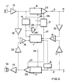
Nachfolgend soll ein Ausführungsbeispiel der erfindungsgemäßen Schaltungsanordnung im Zusammenhang mit der Figur 2 erläutert werden.An exemplary embodiment of the circuit arrangement according to the invention is to be explained below in connection with FIG. 2.
Die Figur 2 zeigt ein Blockschaltbild des Ausführungsbeispieles.FIG. 2 shows a block diagram of the exemplary embodiment.
Die Freisprecheinrichtung gemäß der Figur 2 besteht aus einem Sendesprechweg, der aus einem Mikrofon 17, einem Mikrofonverstärker 15, einem Sendedämpfungsglied 6, einem spannungsgesteuerten Verstärker 23 sowie einer Sendeleitung 2, die die R-Ader der Teilnehmerleitung darstellt, aufgebaut. Die Sprachsignale des Teilnehmers gelangen zusammen mit den Hintergrundgeräuschen auf das Mikrofon 17, das sie in elektrische Signale umsetzt. Vom Ausgang dieses Mikrofons 17 gelangen die gewandelten Sprachsignale über den Mikrofonverstärker 15, sowohl zu dem Sendedämpfungsglied 6 als auch zu einem logarithmischen Verstärker 19, einem Sprachdetektor 4 und einer Geräuschpegelmeßschaltung 21. Dem Sendedämpfungsglied 6 ist der Verstärker 23 nachgeschaltet, der seinerseits mit der Sendeleitung 2 und einem logarithmischen Verstärker 10 verbunden ist. Der Empfängersprechweg besteht in entsprechender Weise aus einem Lautsprecher 16, einem Ausgangsverstärker 14, einem spannungsgesteuerten Verstärker 22, einem Empfängerdämpfungsglied 7 sowie einer Empfängerleitung 3, die die T-Ader der Teilnehmerleitung darstellt. Ein Empfangssignal gelangt über die Empfängerleitung 3 sowohl auf das Empfangsdämpfungsglied 7 als auch auf einen weiteren Sprachdetektor 5 und einen Verstärker 11. Die Ausgangssignale des Verstärkers 10 und des Verstärkers 11 werden auf die Eingänge eines Komparators 8 geführt, dessen Ausgang mit einer Sprachsteuerschaltung 1 verbunden ist. Die Ausgangssignale des zweiten Sprachdetektors 5 werden ebenfalls dieser Sprachsteuerschaltung 1 zugeführt. Dem Empfangsdämpfungsglied 7 ist der Verstärker 22 nachgeschaltet, dessen Ausgangssignale sowohl einem Ausgangsverstärker 14 als auch einem Verstärker 20 zugeführt werden. Der Ausgangsverstärker 14 steuert schließlich den Lautsprecher 16 an. Die Ausgangssignale der Verstärker 19 und 20 werden einem weiteren Komparator 18 zugeführt, dessen Ausgang ebenfalls mit der Sprachsteuerschaltung 1 verbunden ist. Schließlich werden auch die Ausgangssignale des ersten Sprachdetektors 4 dieser Sprachsteuerschaltung 1 zugeführt. Die gleichen Ausgangssignale werde einem Eingang eines NOR-Gliedes 24 zugeführt, dessen Ausgang die Geräuschpegelmeßschaltung 21 ansteuert. Zum Ein- bzw. Ausschalten der Geräuschpegelmeßschaltung 21 kann einem zweiten Eingang 30 des NOR-Gliedes 24 ein Schaltsignal zugeführt werden. Die Geräuschpegelmeßschaltung 21 steuert über eine Steuerleitung 26 den Verstärkungsgrad des Verstärkers 23 und über eine weitere Steuerleitung 27 den Verstärkungsgrad des Verstärkers 22, wogegen die Dämpfung des Sendedämpfungsgliedes 6 über eine von der Sprachsteuerschaltung 1 ausgehenden Steuerleitung 28 und diejenige des Empfangsdämpfungsgliedes 7 über eine ebenfalls von der Sprachsteuerschaltung 1 ausgehenden weiteren Steuerleitung 29 eingestellt werden.The hands-free device according to FIG. 2 consists of a transmission speech path, which consists of a
Die Funktion dieser Freisprechschaltung bezüglich den beiden logarithmischen Verstärkern 10 und 11, dem zugehörigen Komparator 8, dem ersten Sprachdetektor 4 und der Sprachsteuerschaltung 1 entspricht der Freisprechschaltung gemäß der schon eingangs beschriebenen Figur 1, nämlich die Sende- und Empfangspegel auf den Leitungen 2 und 3 sowie die Sprechpausen des einen Teilnehmers zu detektieren, um hieraus mit Hilfe der Sprachsteuerschaltung 1 die entsprechenden Dämpfungswerte an den Dämpfungsgliedern 6 und 7 einstellen zu können. Die beiden weiteren logarithmischen Verstärker 19 und 20, die die Pegel des verstärkten Sprachsignales des einen Teilnehmers bzw. die Pegel des dem Ausgangsverstärkers 14 zugeführten Sprachsignale des anderen Teilnehmers detektieren, der zugehörige zweite Komparator 8 und der zweite Sprachdetektor 5, der die Sprechpausen des anderen Teilnehmers festellt, dienen einer verbesserten Dämpfungssteuerung um somit den Teilnehmern den Eindruck einer natürlichen Konversation zu vermitteln.The function of this hands-free circuit with respect to the two
Erfindungsgemäß werden die am Ausgang des Mikrofonverstärkers 15 anliegenden verstärkten Sprachsignale sowie die Ausgangssignale des ersten Sprachdetektors 4 zur Messung des Hintergrundgeräuschpegels herangezogen. Die Zeitpunkte, zu denen diese Messung durch die Geräuschpegelmeßschaltung 21 erfolgt, werden durch den Sprachdetektor 4 bestimmt, nämlich genau dann, wenn er eine Sprechpause detektiert. Beispielsweise bedeutet ein H-Pegel an dessen Ausgang, daß auf dem Sendesprechweg gerade gesprochen wird, während ein L-Pegel am Ausgang des Sprachdetektors 4 eine augenblickliche Sprechpause anzeigt. Die Geräuschpegelmeßschaltung 21 mißt also den am Mikrofon 17 auftretenden Geräuschpegel nur dann, wenn der Sprachdetektor 4 einen L-Pegel ausgibt. Zur Steuerung der beiden spannungsgesteuerten Verstärker 22 und 23 erzeugt die Geräuschpegelmeßschaltung 21 ein DC-Signal, dessen Wert dem am Mikrofon 17 vorhandenen Geräuschpegel proportional ist. Hierdurch werden die Sende- und Empfangssignale so verstärkt, daß eine entsprechende Kompensation der Hintergrundgeräusche erfolgt.According to the invention, the amplified speech signals present at the output of the
Diese erfindungsgemäße Freisprechschaltung mit einer automatischen Hintergrundgeräuschkompensation erfordert nur wenig zusätzlichen Schaltungsaufwand gegenüber einer bekannten Freisprechschaltung, beispielsweise gemäß der Figur 1, da zur Hintergrundgeräuschkompensation zusätzlich die Ausgangssignale des Mikrofonverstärkers und des Sprachdetektors genutzt werden. Hierdurch ist auch eine wirtschaftliche Herstellung eines solchen Freisprechschaltkreises sichergestellt.This hands-free circuit according to the invention with automatic background noise compensation requires little additional circuitry compared to a known hands-free circuit, for example according to FIG. 1, since the output signals of the microphone amplifier and the speech detector are additionally used for background noise compensation. This also ensures economical manufacture of such a hands-free circuit.
Die erfindungsgemäße Schaltungsanordnung kann nicht nur in analoger sonder auch in digitaler Form aufgebaut werden. Die Geräuschpegelmeßschaltung kann man verschiedenartig realisieren, beispielsweise mit einem Spitzen-Detektor, einer Abtast- und Halteschaltung oder mit einer Integrationsschaltung. Die Steuerung der beiden spannungsgesteuerten Verstärker 22 und 23 kann klassisch mit einem AGC-Signal erfolgen oder mit Hilfe von Multiplikationsschaltungen durchgeführt werden.The circuit arrangement according to the invention can be constructed not only in analog but also in digital form will. The noise level measuring circuit can be implemented in various ways, for example with a tip detector, a sample and hold circuit or with an integration circuit. The two voltage-controlled
Claims (5)
Applications Claiming Priority (2)
| Application Number | Priority Date | Filing Date | Title |
|---|---|---|---|
| DE4012175A DE4012175C2 (en) | 1990-04-14 | 1990-04-14 | Speakerphone |
| DE4012175 | 1990-04-14 |
Publications (3)
| Publication Number | Publication Date |
|---|---|
| EP0452734A2 true EP0452734A2 (en) | 1991-10-23 |
| EP0452734A3 EP0452734A3 (en) | 1993-09-29 |
| EP0452734B1 EP0452734B1 (en) | 1996-10-16 |
Family
ID=6404481
Family Applications (1)
| Application Number | Title | Priority Date | Filing Date |
|---|---|---|---|
| EP91105286A Expired - Lifetime EP0452734B1 (en) | 1990-04-14 | 1991-04-03 | Hands free telephone device |
Country Status (2)
| Country | Link |
|---|---|
| EP (1) | EP0452734B1 (en) |
| DE (2) | DE4012175C2 (en) |
Cited By (3)
| Publication number | Priority date | Publication date | Assignee | Title |
|---|---|---|---|---|
| EP0615397A2 (en) * | 1993-03-11 | 1994-09-14 | Nec Corporation | Noise suppression circuit for radio transceiver microphone |
| EP0763888A2 (en) * | 1995-09-13 | 1997-03-19 | Nokia Mobile Phones Ltd. | Method and circuit arrangement for processing audio signal |
| DE19639580A1 (en) * | 1996-09-26 | 1998-04-09 | Deutsche Telekom Ag | Acoustic echo reduction method for hands-free telephone set |
Families Citing this family (3)
| Publication number | Priority date | Publication date | Assignee | Title |
|---|---|---|---|---|
| DE4337653A1 (en) * | 1993-11-04 | 1995-05-11 | Deutsche Bundespost Telekom | Method and circuit arrangement for improving the quality of voice communication in hands-free telephone facilities |
| DE4447028C1 (en) * | 1994-12-29 | 1996-03-28 | Siemens Ag | Free-speaking device for digital communications peripheral |
| DE10321625B4 (en) * | 2003-05-13 | 2007-08-23 | Gehrke Kommunikationssyteme Gmbh | Signal transmission device and method for regulating a signal transmission device |
Citations (3)
| Publication number | Priority date | Publication date | Assignee | Title |
|---|---|---|---|---|
| US4513177A (en) * | 1980-12-09 | 1985-04-23 | Nippon Telegraph & Telephone Public Corporation | Loudspeaking telephone system |
| US4724540A (en) * | 1986-09-02 | 1988-02-09 | Motorola, Inc. | Speakerphone with fast idle mode |
| US4829565A (en) * | 1987-10-20 | 1989-05-09 | Goldberg Robert M | Telephone with background volume control |
Family Cites Families (7)
| Publication number | Priority date | Publication date | Assignee | Title |
|---|---|---|---|---|
| DE2414143B2 (en) * | 1973-03-28 | 1981-01-15 | Rediffusion Reditronics Ltd., St. Helier, Jersey, Kanal-Inseln (Ver. Koenigreich) | Loudspeaker system with an adjustable audio amplifier |
| DE3148305A1 (en) * | 1981-12-03 | 1983-06-09 | Deutsche Telephonwerke Und Kabelindustrie Ag, 1000 Berlin | CIRCUIT ARRANGEMENT FOR A HANDS-FREE UNIT |
| US4490582A (en) * | 1983-02-18 | 1984-12-25 | At&T Information Systems Inc. | Speakerphone control circuit |
| DE3318742C2 (en) * | 1983-05-21 | 1986-12-04 | Krone Gmbh, 1000 Berlin | Analog automatic voice control, especially for a telephone with a hands-free device |
| CA1233925A (en) * | 1985-05-10 | 1988-03-08 | Gordon J. Reesor | Digital loudspeaking telephone |
| DE3629596A1 (en) * | 1986-08-30 | 1988-03-03 | Standard Elektrik Lorenz Ag | CIRCUIT ARRANGEMENT FOR DECOUPLING THE TRANSFER BRANCHES OF A HANDS-FREE UNIT |
| CA1291837C (en) * | 1987-07-15 | 1991-11-05 | Juro Ohga | Electronic telephone terminal having noise suppression function |
-
1990
- 1990-04-14 DE DE4012175A patent/DE4012175C2/en not_active Expired - Fee Related
-
1991
- 1991-04-03 DE DE59108276T patent/DE59108276D1/en not_active Expired - Fee Related
- 1991-04-03 EP EP91105286A patent/EP0452734B1/en not_active Expired - Lifetime
Patent Citations (3)
| Publication number | Priority date | Publication date | Assignee | Title |
|---|---|---|---|---|
| US4513177A (en) * | 1980-12-09 | 1985-04-23 | Nippon Telegraph & Telephone Public Corporation | Loudspeaking telephone system |
| US4724540A (en) * | 1986-09-02 | 1988-02-09 | Motorola, Inc. | Speakerphone with fast idle mode |
| US4829565A (en) * | 1987-10-20 | 1989-05-09 | Goldberg Robert M | Telephone with background volume control |
Non-Patent Citations (1)
| Title |
|---|
| JOURNAL OF THE AUDIO ENGINEERING SOCIETY, Bd. 36, Nr. 1-2, Januar 1988, NEW YORK, US; Seiten 18 - 26, XP5778; W.J.W. KITZEN ET AL.: 'Noise-Dependent Sound Reproduction in a Car: Application of a Digital Audio Signal Processor' * |
Cited By (8)
| Publication number | Priority date | Publication date | Assignee | Title |
|---|---|---|---|---|
| EP0615397A2 (en) * | 1993-03-11 | 1994-09-14 | Nec Corporation | Noise suppression circuit for radio transceiver microphone |
| EP0615397A3 (en) * | 1993-03-11 | 1994-10-19 | Nec Corp | Noise suppression circuit for radio transceiver microphone. |
| US5903853A (en) * | 1993-03-11 | 1999-05-11 | Nec Corporation | Radio transceiver including noise suppressor |
| EP0763888A2 (en) * | 1995-09-13 | 1997-03-19 | Nokia Mobile Phones Ltd. | Method and circuit arrangement for processing audio signal |
| EP0763888A3 (en) * | 1995-09-13 | 1998-02-11 | Nokia Mobile Phones Ltd. | Method and circuit arrangement for processing audio signal |
| US5907823A (en) * | 1995-09-13 | 1999-05-25 | Nokia Mobile Phones Ltd. | Method and circuit arrangement for adjusting the level or dynamic range of an audio signal |
| DE19639580A1 (en) * | 1996-09-26 | 1998-04-09 | Deutsche Telekom Ag | Acoustic echo reduction method for hands-free telephone set |
| DE19639580C2 (en) * | 1996-09-26 | 1998-09-17 | Deutsche Telekom Ag | Device for reducing acoustic echoes |
Also Published As
| Publication number | Publication date |
|---|---|
| DE4012175A1 (en) | 1991-10-17 |
| DE59108276D1 (en) | 1996-11-21 |
| EP0452734A3 (en) | 1993-09-29 |
| DE4012175C2 (en) | 1995-04-13 |
| EP0452734B1 (en) | 1996-10-16 |
Similar Documents
| Publication | Publication Date | Title |
|---|---|---|
| DE3001362C3 (en) | Circuit arrangement for regulating the supply current for centrally supplied telephone sets | |
| EP0290952B1 (en) | Speech control circuitry for a telecommunication terminal | |
| EP0120325B1 (en) | Circuit arrangement for a hands free telephone | |
| DE3231108A1 (en) | VOICE TRANSFER DEVICE WITH LINE-RECEIVER CONDITIONING CIRCUIT | |
| DE19517469A1 (en) | Hands-free procedure for a multi-channel transmission system | |
| DE2313247A1 (en) | CIRCUIT ARRANGEMENT FOR A TELEPHONE WITH VOICE-CONTROLLED HANDS-FREE DEVICE | |
| DE1156442B (en) | Circuit arrangement for reducing the background noise sensitivity of voice-controlled loudspeaker devices | |
| DE2659028C3 (en) | Circuit arrangement for preventing feedback | |
| EP0452734B1 (en) | Hands free telephone device | |
| DE2163126C3 (en) | Amplifier arrangement for a telephone set | |
| DE2131196A1 (en) | Circuit for telephone systems | |
| DE1166278B (en) | Circuit for echo suppression in a two-way signal transmission system | |
| DE2728854A1 (en) | TWO-DIRECTIONAL VOICE CONTROL UNIT | |
| DE2826671C3 (en) | Circuit arrangement for a telephone with a speakerphone | |
| DE3046488C2 (en) | Arrangement to compensate for the different attenuation behavior of telecommunication lines | |
| EP0193733B1 (en) | Method for matching a hybrid amplifier circuit to a telecommunication line, and device for carrying it out | |
| DE3839627C2 (en) | Telephone device | |
| DE2751261C3 (en) | Circuit arrangement for a hands-free telephone with automatic signal amplitude limitation | |
| DE2411501C3 (en) | Circuit arrangement and method for operating a loudspeaker device | |
| EP0584649B1 (en) | Circuit for electro-acoustic devices | |
| EP0099013A2 (en) | Device for the equalization of differing attenuation characteristics of telecommunication lines | |
| DE962984C (en) | Method for avoiding disturbances occurring in multi-channel carrier frequency systems, in particular from overdriving phenomena in the carrier frequency intermediate amplifiers | |
| CH626485A5 (en) | Circuit arrangement for a hands-free telephone | |
| DE3805357A1 (en) | Circuit arrangement for dynamic range control of speech signals | |
| DE4021206C2 (en) |
Legal Events
| Date | Code | Title | Description |
|---|---|---|---|
| PUAI | Public reference made under article 153(3) epc to a published international application that has entered the european phase |
Free format text: ORIGINAL CODE: 0009012 |
|
| AK | Designated contracting states |
Kind code of ref document: A2 Designated state(s): DE FR GB IT SE |
|
| RAP1 | Party data changed (applicant data changed or rights of an application transferred) |
Owner name: TEMIC TELEFUNKEN MICROELECTRONIC GMBH |
|
| PUAL | Search report despatched |
Free format text: ORIGINAL CODE: 0009013 |
|
| AK | Designated contracting states |
Kind code of ref document: A3 Designated state(s): DE FR GB IT SE |
|
| 17P | Request for examination filed |
Effective date: 19931122 |
|
| 17Q | First examination report despatched |
Effective date: 19950512 |
|
| GRAG | Despatch of communication of intention to grant |
Free format text: ORIGINAL CODE: EPIDOS AGRA |
|
| GRAH | Despatch of communication of intention to grant a patent |
Free format text: ORIGINAL CODE: EPIDOS IGRA |
|
| GRAH | Despatch of communication of intention to grant a patent |
Free format text: ORIGINAL CODE: EPIDOS IGRA |
|
| GRAA | (expected) grant |
Free format text: ORIGINAL CODE: 0009210 |
|
| ITF | It: translation for a ep patent filed |
Owner name: DE DOMINICIS & MAYER S.R.L. |
|
| AK | Designated contracting states |
Kind code of ref document: B1 Designated state(s): DE FR GB IT SE |
|
| GBT | Gb: translation of ep patent filed (gb section 77(6)(a)/1977) |
Effective date: 19961001 |
|
| REF | Corresponds to: |
Ref document number: 59108276 Country of ref document: DE Date of ref document: 19961121 |
|
| ET | Fr: translation filed | ||
| PG25 | Lapsed in a contracting state [announced via postgrant information from national office to epo] |
Ref country code: GB Effective date: 19970403 |
|
| PG25 | Lapsed in a contracting state [announced via postgrant information from national office to epo] |
Ref country code: SE Effective date: 19970404 |
|
| PLBE | No opposition filed within time limit |
Free format text: ORIGINAL CODE: 0009261 |
|
| STAA | Information on the status of an ep patent application or granted ep patent |
Free format text: STATUS: NO OPPOSITION FILED WITHIN TIME LIMIT |
|
| 26N | No opposition filed | ||
| GBPC | Gb: european patent ceased through non-payment of renewal fee |
Effective date: 19970403 |
|
| PG25 | Lapsed in a contracting state [announced via postgrant information from national office to epo] |
Ref country code: FR Free format text: LAPSE BECAUSE OF NON-PAYMENT OF DUE FEES Effective date: 19971231 |
|
| EUG | Se: european patent has lapsed |
Ref document number: 91105286.8 |
|
| REG | Reference to a national code |
Ref country code: FR Ref legal event code: ST |
|
| PGFP | Annual fee paid to national office [announced via postgrant information from national office to epo] |
Ref country code: DE Payment date: 19980417 Year of fee payment: 8 |
|
| PG25 | Lapsed in a contracting state [announced via postgrant information from national office to epo] |
Ref country code: DE Free format text: LAPSE BECAUSE OF NON-PAYMENT OF DUE FEES Effective date: 20000201 |
|
| PG25 | Lapsed in a contracting state [announced via postgrant information from national office to epo] |
Ref country code: IT Free format text: LAPSE BECAUSE OF NON-PAYMENT OF DUE FEES Effective date: 20050403 |